EP2181037B1 - Device for attaching an aircraft engine including a thrust force collection device with reduced overall dimensions - Google Patents
Device for attaching an aircraft engine including a thrust force collection device with reduced overall dimensions Download PDFInfo
- Publication number
- EP2181037B1 EP2181037B1 EP08787412A EP08787412A EP2181037B1 EP 2181037 B1 EP2181037 B1 EP 2181037B1 EP 08787412 A EP08787412 A EP 08787412A EP 08787412 A EP08787412 A EP 08787412A EP 2181037 B1 EP2181037 B1 EP 2181037B1
- Authority
- EP
- European Patent Office
- Prior art keywords
- fitting
- engine
- attachment
- rigid structure
- plate
- Prior art date
- Legal status (The legal status is an assumption and is not a legal conclusion. Google has not performed a legal analysis and makes no representation as to the accuracy of the status listed.)
- Active
Links
- 230000005540 biological transmission Effects 0.000 claims abstract description 6
- 230000002093 peripheral effect Effects 0.000 claims description 4
- 238000011084 recovery Methods 0.000 description 18
- 241000920340 Pion Species 0.000 description 3
- 230000000149 penetrating effect Effects 0.000 description 3
- XEEYBQQBJWHFJM-UHFFFAOYSA-N Iron Chemical compound [Fe] XEEYBQQBJWHFJM-UHFFFAOYSA-N 0.000 description 2
- 230000008878 coupling Effects 0.000 description 2
- 238000010168 coupling process Methods 0.000 description 2
- 238000005859 coupling reaction Methods 0.000 description 2
- 238000012423 maintenance Methods 0.000 description 2
- BASFCYQUMIYNBI-UHFFFAOYSA-N platinum Chemical compound [Pt] BASFCYQUMIYNBI-UHFFFAOYSA-N 0.000 description 2
- 230000003014 reinforcing effect Effects 0.000 description 2
- 238000005204 segregation Methods 0.000 description 2
- 239000000470 constituent Substances 0.000 description 1
- 239000000446 fuel Substances 0.000 description 1
- 229910052742 iron Inorganic materials 0.000 description 1
- 238000002955 isolation Methods 0.000 description 1
- 239000007769 metal material Substances 0.000 description 1
- 238000012986 modification Methods 0.000 description 1
- 230000004048 modification Effects 0.000 description 1
- 229910052697 platinum Inorganic materials 0.000 description 1
- 230000002787 reinforcement Effects 0.000 description 1
- 239000000725 suspension Substances 0.000 description 1
Images


Classifications
-
- B64D27/40—
-
- B64D27/402—
-
- B64D27/406—
Definitions
- the present invention relates generally to a device for attaching an aircraft engine, for example intended to be interposed between an aircraft wing and the engine concerned, to an engine assembly comprising such a coupling device. , and to an aircraft comprising at least one such attachment device
- the invention can be used on any type of aircraft equipped with turbojet engines or turboprop engines.
- This type of attachment device also known as the "Engine Mounting Structure” (EMS)
- EMS Engine Mounting Structure
- Such an attachment device is in fact provided to form the connecting interface between a turbine engine and a wing of the aircraft. It makes it possible to transmit to the structure of this aircraft the forces generated by its associated turbine engine, and also allows the flow of fuel, systems electric, hydraulic, and air between the engine and the aircraft.
- the attachment device comprises a rigid structure, called primary structure, often of the "box” type, that is to say formed by the assembly of upper and lower spars and panels laterally connected via transverse ribs.
- the device is provided with hooking means interposed between the turbine engine and the rigid structure, these means generally comprising two engine attachments, and a device for taking up the thrust forces generated by the turbine engine.
- this recovery device comprises for example two lateral rods connected on the one hand to the casing of the turbine engine, and on the other hand reported on a spreader, itself hinged to the rigid structure of the attachment device.
- the attachment device also comprises another series of fasteners constituting a mounting system interposed between the rigid structure and the wing of the aircraft, this system usually consisting of two or three fasteners.
- the mast is provided with a secondary structure ensuring the segregation and maintenance of the systems while supporting aerodynamic fairings.
- the thrust force recovery device incorporates a spreader hinged to the rigid structure, via a connecting pin.
- the lifter is usually made using two superposed fittings, as well as the axis of binding takes the form of a doubled focus.
- the other fitting which ensures only the recovery of the forces coming from the lateral connecting rods, and, in case of breakage of the external axis of the doubled connection axis, it is then the inner axis that takes over for the recovery and transmission of these same forces in the longitudinal direction.
- Fastening devices are known from the prior art as in the document EP 0879759 , in which the rear engine attachment and the thrust load recovery device are separate and offset longitudinally.
- the attachment of the engine to the lower spar of the box is effected by means of a fixed shaft of the motor and passing through the spar. This axis is generally inclined relative to the vertical direction. This inclination makes the assembly complex and requires the use of special tools to allow such a fixation.
- an aircraft engine coupling device comprising a rear engine attachment fixed to a box by two side fittings taking up the vertical forces and a force recovery device comprising two connecting rods connected to a lifter mechanically connected to the box by a connection fitting, in which the fail-safe function in case of breakage of a connecting rod is provided by one of the two side brackets.
- thrust forces and lateral forces are resumed by the box by a push pin mounted in the connection fitting.
- the hooking device is simplified by using the side fittings as a rudder stop, which makes it possible to eliminate the abutments that are attached to the box.
- the fail-safe function of the mechanical connection between the lifter and the rear attachment is provided by doubling the connection fitting.
- connection fittings are nested, which reduces the size of the device.
- the attachment device has the advantage of allowing easier disassembly of the engine, since there are only two interface points between the engine and the box.
- the present invention therefore mainly relates to an attachment device of an aircraft engine comprising a rigid structure and means for attaching said engine to said rigid structure, said attachment means comprising a rear engine attachment and a device of the thrust forces generated by the engine, the rear engine attachment being fixed on the rigid structure by means of two side fittings fixed to the rigid structure, said force recovery device comprising two connecting rods mechanically linked to a lifter by a mechanical connection, a connection fitting fixed to the rear engine attachment and mechanically linked to the rigid structure by a thrust pin, wherein the side fittings comprise stop means for limiting the tilting of the rudder in the event of rupture of a connecting rod and ensuring the transmission of the thrust forces generated by the engine to the rigid structure .
- connection fitting is of the fail-safe type, for example it comprises an inner fitting and an outer fitting.
- the outer fitting comprises a hollow body and a plate extending forwardly of said casing and the inner fitting comprises a body which is housed in the hollow body of the outer fitting and comprising a plate extending forward from the body parallel to the first plate, the two plates forming a yoke to which is mechanically connected the rudder.
- the spreader may then comprise a first and a third portion forming a yoke and surrounding the yoke of the connecting fitting and a second portion interposed between the first and the third part, said second part penetrating into the yoke of the connection fitting.
- the outer fitting comprises a body formed by a bottomless bottom housing, and a clevis extending forwardly from a front wall of the housing, said front wall comprises a porting light.
- the inside of the housing and the space between the legs of the yoke and the inner fitting comprises a body being housed in the body of the external fitting and a plate passing through the light of the front wall and being housed between the branches of the yoke , the spreader comprising two parts forming a yoke, said yoke receiving the plate of the inner fitting and being received in the yoke of the outer fitting.
- the bodies of the outer and inner fittings each comprise means for fastening peripheral attachment to the rear engine attachment by traction screws, the fastening means of the inner fitting being clamped between the fastening means of the outer fitting and the rear engine attachment; This allows the same traction screws to be used to attach the two brackets to the rear engine mount.
- These fixing means may be of the flange or leg type.
- each side fitting comprises a first plate fixed by bolting on the rigid structure and a second plain orthogonal to the first plate and substantially parallel to a lower spar of the rigid structure, the rear engine attachment comprising a base fixed by means of tensile screws to the rigid structure.
- Said second plate may also comprise at least two slots, the base being provided with protruding pins, said pins having bores orthogonal to their axis, the pins passing through the second plate by said slots and an axis being mounted in each bore of the pions. . These pins take the lateral forces and may, in case of breakage of one of the side fittings, resume the moment along the longitudinal axis.
- the fittings have abutment surfaces against which the rudder is intended to bear in case of rupture of one of the connecting rods.
- the thrust axis is doubled and has an inner axis and an outer axis.
- the mechanical linkage axes between the lifter and the connection fitting can also be doubled.
- the present invention also relates to an engine assembly comprising a motor and an attachment device of the engine, said attachment device being a device according to the present invention.
- the present invention also relates to an aircraft comprising at least one engine assembly according to the present invention, assembled on a wing or on a rear fuselage of this aircraft.
- this assembly 1 comprising an attachment pylon 4 according to a preferred embodiment of the present invention.
- the engine assembly 1 is composed of a motor such as a turbojet engine 2 and the attachment pylon 4, the latter being provided in particular with a plurality of engine fasteners 6, 8, 9 and a structure rigid 10 carrying these same fasteners.
- the assembly 1 is intended to be surrounded by a nacelle (not shown), and that the attachment pylon 4 comprises another series of fasteners (not shown) to ensure the suspension of this assembly 1 under the wing of the aircraft.
- X is the longitudinal direction of the mast 4 which is also comparable to the longitudinal direction of the turbojet engine 2, this direction X being parallel to a longitudinal axis 5 of the turbojet engine 2.
- Y is the direction transversely oriented with respect to the mast 4 and also comparable to the transverse direction of the turbojet 2
- Z is the vertical or height direction, these three directions X, Y and Z being orthogonal to one another.
- front and rear are to be considered in relation to a direction of advancement of the aircraft encountered following the thrust exerted by the turbojet engine 2, this direction being represented schematically by the arrow 7.
- the rigid structure 10 is in the conventional form of a box formed by an upper spar 18 and a lower spar 20 both extending in the direction X and substantially in an XY plane or slightly inclined relative to the latter, as well as two lateral panels 22 (only one being visible on the figure 1 ) both extending in the X direction and substantially in a XZ plane.
- transverse ribs 24 arranged along YZ planes and spaced longitudinally reinforce the rigidity of the rigid structure 10. It is noted as an indication that the elements 18, 20, 22 can each be made in one piece, or by the assembly of contiguous sections.
- the turbojet engine 2 has at the front of a large fan casing 12 delimiting an annular fan duct 14, and comprises a rearward central casing 16 of smaller size, enclosing the center of the fan. this turbojet. Finally, the central casing 16 is extended towards the rear by an ejection casing 17 of larger size than that of the casing 16.
- the housings 12, 16 and 17 are of course integral with each other.
- the plurality of engine attachments is formed by a front engine attachment 6, a rear engine attachment 8 forming in fact two rear half-fasteners, and a fastener 9 forming a device for taking up the thrust forces generated by the turbine engine 2
- this device 9 takes for example the form of two lateral rods 26 (only one being visible due to the side view) connected on the one hand to a rear portion of the fan casing 12, and on the other hand to a rudder 28 mounted on the rear attachment 8 by two axes 29.
- FIG. 2 On the figure 2 a three-quarter perspective view of a first embodiment of an attachment device according to the present invention can be seen.
- the attachment device comprises the rear engine attachment 8 and the recovery device thrust forces 9 fixed on the rear engine attachment 8.
- the attachment device comprises a plane of symmetry P indicated on the figures 1 and 3 and extending in directions X and Z.
- the rear engine attachment 8 comprises a body formed of a base 32 intended to be disposed on the side of the lower spar 20 forming the lower end of the box 10.
- the body also comprises a support bracket 34 substantially in the form of a circular arc fixed under the base opposite the lower beam 20.
- the base 32 and the support bracket 34 are made of a single piece of metal material.
- the support fitting 34 comprises a right end 34a and a left end 34b connected to the motor, more particularly to the fan casing by shackles 35a, 35b, to which they are mechanically connected by pins (not shown).
- the rear engine attachment 8 then forms, as described above, two half-fasteners, a right half-attachment 8a and a left half-attachment 8b.
- the rear engine attachment 8 is fixed to the box, by means of two side fittings arranged on the basis of the plane of symmetry of the box and fixed by bolting on the box 10, a right side fitting 36a and a left side fitting 36b.
- the right and left are considered in relation to the plane P and looking from the front towards the back, ie from the fastener 6 to the fastener 8 on the figure 1 .
- the lateral fitting 36a comprises a first plate 38a contained in an XZ plane and a second plate 40a disposed at right angles in an XY plane, the first plate 38a being fixed by splicing between a lateral wing (not shown) of the lower beam 20 contained in an XZ plane and a side panel 22.
- the second plate 38a is contained in an XY plane parallel to the lower beam 20 at a distance therefrom, allowing the rear engine attachment 8 to be mounted on the side fittings, as will be seen later.
- the base 32 comprises, in the example shown, projecting from its face 32a facing a lower face of the lower spar 20, two pairs of pins 42, each disposed symmetrically on each side of the plane of symmetry P;
- the pins 42 of each pair are aligned in the direction X and have a bore 44 of X direction.
- the number of pions may be greater than two, that one could provide more than one pair of pions on either side of the plane of symmetry P.
- the left side fitting 36a has two lights 46a made in the second platen 40a contained in the plane XY and disposed relative to each other correspondingly to the arrangement of the pins 42.
- the pair of pins 42 are mounted in the pair of lights 46a made on the side of a lower face of the second plate 40a and opens between an upper face of the second plate 40 and the lower beam 20.
- Each bore 44 of the pins 42 receives an axis (not shown) along the X axis.
- the base 32 is fixed to the box by means of pulling screws (not shown), for example two on each side. These traction screws allow a recovery of forces along the Z axis and a recovery of the moment according to X.
- the pins via the axles ensure the recovery of forces along the Z axis of the rear engine attachment 8 on the box in case of rupture of the traction screws.
- the pins 42 are mounted with clearance in the plate 40, so they do not resume the moment along X in case of rupture of a side fitting.
- Fixing the pair of pins 42 right on the left side fitting 36b is similar to that of the left pair of pegs and therefore will not be described in detail.
- the thrust force recovery device comprises a connection fitting 49 disposed between the base 32 and the lower spar 20 and fixed on the upper face. of the base 32 symmetrically with respect to the plane of symmetry P.
- this fitting is doubled to ensure the "fail-safe" function.
- connection fitting is in fact composed of an external connection fitting 50 and an internal connection fitting 56 housed in the external connection fitting 50.
- the external connection fitting comprises a body 51 provided with fixing lugs 52 protruding from its periphery, each provided with at least one bore 54 for attachment to the base 32 by means of traction screws (not shown).
- the fitting comprises two lateral lugs 52 provided with a bore 54 and a lug 52 projecting from a rear end of the connecting fitting 50 and provided with three bores 54.
- reinforcement ribs 57 are provided between the fastening tabs 52 and the body 51 so as to increase the rigidity of the fastener.
- the body 51 comprises a central bore 58 for receiving a first end of the thrust pin 60 for transmitting the thrust forces of the connection fitting 50 to the box, a second end of the pin 60 being mounted in the box 10.
- the body 51 extends forwardly by a plate 62 provided with a bore 64 receiving an axis 66 of mechanical connection of the spreader 28.
- the plate 62 is inclined forwardly downward substantially in the direction of the connecting rods 26.
- connection fitting 50 The body 51 of the connection fitting 50 is delimited by side walls, a rear wall and an upper wall defining a hollow volume, and accommodates the inner connection fitting 56, thus forming a "fail-safe" connection fitting.
- the inner connection fitting 56 has substantially the same shape as the fitting 50, it comprises a body 68 and lateral and rear tabs 70 sandwiched between the tabs 52 and the base 32, and a plate 72 extending towards the before parallel to the plate 62, provided with a bore 73 for the passage of the axis 66.
- the body 68 also has a bore 75 facing the bore 58 of the body 51 to receive an end of the thrust pin 60.
- the two plates 62, 72 extend parallel to each other at a distance, defining a space for receiving a part of the spreader 28.
- a simple connection fitting 49 that is to say one which does not consist of two fittings, does not of course go outside the scope of the present invention.
- the spreader 28 is formed of a first 28.1, a second 28.2 and a third 28.3 superimposed parts and ensuring the function "fail-safe" in case of breakage of one of them.
- the first 28.1 and third 28.3 parts are respectively disposed above the plate 62 and below the plate 72, and the second portion 28.2 is disposed in the space between the plates 62, 72
- the plate 62 is sandwiched between the first 28.1 and the second 28.2 part of the spreader 28 and the plate 72 is sandwiched between the second 28.2 and third 28.3 part of the spreader 28.
- a recess 76 is hollowed out in the face of the first part 28.1 in contact with the plate 62
- a recess 78 is hollowed out in the face of the second part 28.2 in contact with the plate 72. imprints 76, 78 reduce the thickness of the rudder.
- cavities 76, 78 have a V-shape whose opening is oriented rearwardly so as to allow the pivoting bar to pivot about the axis 66 relative to the connection fittings 50, 56.
- the spreader 28 in case of breakage of a connecting rod 26, the spreader 28 abuts against the side fitting 36 on the side of the rod 26 intact, which makes it possible not to use additional stop fitting.
- each lateral fitting 36a, 36 has a portion 80 projecting forwardly at the connection between the first 38a and the second 40a platinum ending by a stop plate 82 extending substantially in directions Y and Z.
- a reinforcing rib 84 is provided under the projecting portion 80.
- the forces generated by the motor and acting in the direction X are transmitted from the connecting rods 26 to the spreader 28 via the pins 29, and then from the spreader bar 28 to the connection fittings 50, 56 by the axis 29, then connecting fittings 50 , 56 to the caisson by the thrust pin 60.
- a greater or lesser part of the thrust forces is taken up by the rudder, the axis 66 and the connection fitting.
- the internal connection fitting 56 takes over and transmits the forces of the spreader 28 to the box 10 via the thrust pin 60.
- the moment according to X is taken up on the rear attachment by the traction screws on each side of the fastener. In case of rupture of one or more traction screws, the moment according to X is taken up by the pins 42.
- the axis 60 is of the "fail-safe" type, ie it is double, it comprises, as can be seen on the figure 4 , an outer axis 60.1 and an inner axis 60.2, and in case of rupture of the outer axis 60.1, the inner axis 60.2 takes over.
- the axis 66 is of the "fail-safe" type, ie it is double, it has an outer axis and an inner axis, and in the event of rupture of the outer axis, the inner axis takes relay.
- this device according to the second embodiment differs mainly from the device according to the first embodiment in the structures of the connection fittings and the rudder.
- connection fitting 149 advantageously made by two iron fittings. nested connections one inside the other, an external fitting 150 and an interior fitting 152.
- the external fitting 150 comprises a body 151 lined laterally and rearwardly by a fastening flange 161 pierced with bores 154 to allow the attachment of the first fitting 150 to the base 32 by means of pulling screws (not shown). .
- the body 151 is delimited by two side walls 153, an upper wall 155, a rear wall 157, and a front wall 159.
- the body 151 also has a bore 160 substantially in the center of its upper wall 155 to receive an end of a thrust pin 60.
- the external connection fitting 150 also comprises a yoke 162 extending from the front wall 159, this yoke receiving the rudder bar 128.
- the yoke 162 is inclined forwards substantially downwards in the direction of inclination of the connecting rods 26a, 26b.
- Clevis 162 is pierced with a bore 164 receiving an axis 166.
- the front wall 159 is pierced to allow the passage of a plate 168 of the second fitting 152.
- the inner fitting 152 comprises a body 170 of shape and dimensions capable of penetrating the body 151 of the first fitting 150 and the plate 168 projecting from a front face of the body 170.
- the body 170 comprises a peripheral flange 172 also pierced with bores corresponding to those of the flange 156 of the external fitting 150 and interposed between the flange 156 of the outer fitting and the base 32.
- the body 170 has a bore 171 facing the bore 160 of the body 151 to receive the end of the thrust axis 60.
- the plate 168 has a bore 169 facing those of the yoke 162 for the passage of the axis 166.
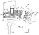
- the plate When the internal fitting 152 is placed in the external fitting 150, the plate passes through the front wall 159 of the body 151 of the external connection fitting 150 and is housed between the two branches of the cap 162, as is particularly visible on the figure 9 .
- the plate 168 extends parallel to the legs of the yoke 162 and at a distance therefrom, thus providing two spaces.
- a simple connection fitting 149 that is to say which is not composed of two fittings, does not of course go beyond the scope of the present invention.
- the spreader bar 128 is formed of two spreaders 128.1, 128.2 respectively penetrating into the spaces formed between the yoke 162 and the plate 168.
- the two spreaders 128.1, 128.2 are of similar shape and advantageously comprise a recess 178, 180 on their face in contact with the plate 168 to receive this plate 168.
- Each lifter 128.1, 128.2 has two lateral bores for connection to connecting rods 26a, 26b and a central bore for connection to connection fittings 150, 152.
- the recesses 178, 180 have a V-shape, the opening of which is directed towards the rear, allowing pivoting of the rudder about the axis 168.
- each lateral fitting 36a has a portion 80 projecting forwardly at the connection between the first 38a and the second 40a plate ending in a stop plate 82 extending substantially in directions Y and Z.
- a reinforcing rib 84 is provided under the projecting portion 80.
- the recesses 178, 180 allow an angle of rotation sufficient to allow the rudder to abut against one of the portions 80 projecting side fittings.
- a greater or lesser part of the thrust forces is taken up by the rudder, the axis 66 and the connection fitting.
- the other spreader transmits the thrust forces transmitted by the connecting rods 26a, 26b to the thrust pin 60.
- the internal connection fitting 152 takes over and transmits the forces of the spreader 128 to the box 10 via the thrust axis 60.
- the moment according to X is taken up on the rear attachment by the traction screws on each side of the fastener. In case of rupture of one or more traction screws, the moment according to X is taken up by the pins 42.
- the axis 60 is advantageously of the "fail-safe" type, ie it is double, it comprises as can be seen on the figure 8 and 9 an outer axis 60.1 and an inner axis 60.2, so in case of rupture of the outer axis 60.1, the inner axis 60.2 takes over.
- the axis 166 is advantageously of the "fail-safe" type, ie it is double, the latter comprises an outer axis and an inner axis, thus case of rupture of the outer axis, the inner axis takes over.
- connection fitting could be modified according to the configuration of the available space, as well as the shape and the number of parts composing the lifter.
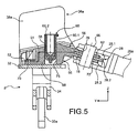
- connection fitting 49 is of the fail-safe type and comprises in fact two fittings 50, 56 one inside the other, the axis 66 between the spreader and this fitting is mounted without play in the two fittings ( figure 5 ). Consequently, the two fittings are solicited simultaneously during normal operation, this also applies to the second embodiment.
Abstract
Description
La présente invention se rapporte de façon générale à un dispositif d'accrochage d'un moteur d'aéronef, par exemple destiné à être interposé entre une voilure d'aéronef et le moteur concerné, à un ensemble moteur comprenant un tel dispositif d'accrochage, ainsi qu'à un aéronef comportant au moins un tel dispositif d'accrochageThe present invention relates generally to a device for attaching an aircraft engine, for example intended to be interposed between an aircraft wing and the engine concerned, to an engine assembly comprising such a coupling device. , and to an aircraft comprising at least one such attachment device
L'invention peut être utilisée sur tout type d'aéronef équipé de turboréacteurs ou de turbopropulseurs.The invention can be used on any type of aircraft equipped with turbojet engines or turboprop engines.
Ce type de dispositif d'accrochage, également appelé mât d'accrochage ou « EMS » (de l'anglais «Engine Mounting Structure»), peut indifféremment être employé pour suspendre un moteur au-dessous de la voilure de l'aéronef, monter ce moteur au-dessus de cette même voilure, ou bien encore pour rapporter ce moteur en partie arrière du fuselage de l'aéronef.This type of attachment device, also known as the "Engine Mounting Structure" (EMS), can equally be used to suspend an engine below the wing of the aircraft, to mount this engine above the same wing, or to bring the engine back part of the fuselage of the aircraft.
Un tel dispositif d'accrochage est en effet prévu pour former l'interface de liaison entre un turbomoteur et une voilure de l'aéronef. Il permet de transmettre à la structure de cet aéronef les efforts générés par son turbomoteur associé, et autorise également le cheminement du carburant, des systèmes électriques, hydrauliques, et air entre le moteur et l'aéronef.Such an attachment device is in fact provided to form the connecting interface between a turbine engine and a wing of the aircraft. It makes it possible to transmit to the structure of this aircraft the forces generated by its associated turbine engine, and also allows the flow of fuel, systems electric, hydraulic, and air between the engine and the aircraft.
Afin d'assurer la transmission des efforts, le dispositif d'accrochage comporte une structure rigide, dite structure primaire, souvent du type « caisson », c'est-à-dire formée par l'assemblage de longerons supérieurs et inférieurs et de panneaux latéraux raccordés entre eux par l'intermédiaire de nervures transversales.To ensure the transmission of forces, the attachment device comprises a rigid structure, called primary structure, often of the "box" type, that is to say formed by the assembly of upper and lower spars and panels laterally connected via transverse ribs.
D'autre part, le dispositif est muni de moyens d'accrochage interposés entre le turbomoteur et la structure rigide, ces moyens comportant globalement deux attaches moteur, ainsi qu'un dispositif de reprise des efforts de poussée générés par le turbomoteur.On the other hand, the device is provided with hooking means interposed between the turbine engine and the rigid structure, these means generally comprising two engine attachments, and a device for taking up the thrust forces generated by the turbine engine.
Dans l'art antérieur, ce dispositif de reprise comprend par exemple deux bielles latérales raccordées d'une part au carter du turbomoteur, et d'autre part rapportées sur un palonnier, lui-même articulé sur la structure rigide du dispositif d'accrochage.In the prior art, this recovery device comprises for example two lateral rods connected on the one hand to the casing of the turbine engine, and on the other hand reported on a spreader, itself hinged to the rigid structure of the attachment device.
De la même façon, le dispositif d'accrochage comporte également une autre série d'attaches constituant un système de montage interposé entre la structure rigide et la voilure de l'aéronef, ce système étant habituellement composé de deux ou trois attaches.In the same way, the attachment device also comprises another series of fasteners constituting a mounting system interposed between the rigid structure and the wing of the aircraft, this system usually consisting of two or three fasteners.
Enfin, le mât est pourvu d'une structure secondaire assurant la ségrégation et le maintien des systèmes tout en supportant des carénages aérodynamiques.Finally, the mast is provided with a secondary structure ensuring the segregation and maintenance of the systems while supporting aerodynamic fairings.
Comme cela a été évoqué ci-dessus, les solutions proprosées antérieurement prévoient que le dispositif de reprise des efforts de poussée intègre un palonnier articulé sur la structure rigide, par l'intermédiaire d'un axe de liaison. A ce titre, il est indiqué que, pour assurer une fonction dite « Fail Safe » pour la transmission d'efforts selon la direction longitudinale, le palonnier est habituellement réalisé à l'aide de deux ferrures superposées, de même que l'axe de liaison prend quant à lui la forme d'un axé doublé. Ainsi, en cas de rupture de l'une des deux ferrures superposées constituant le palonnier, c'est l'autre ferrure qui assure seule la reprise des efforts provenant des bielles latérales, et, en cas de rupture de l'axe extérieur de l'axe de liaison doublé, c'est alors l'axe intérieur qui prend le relais pour la reprise et la transmission de ces mêmes efforts selon la direction longitudinale.As mentioned above, the previously proposed solutions provide that the thrust force recovery device incorporates a spreader hinged to the rigid structure, via a connecting pin. As such, it is indicated that, to ensure a so-called "Fail Safe" function for the transmission of forces in the longitudinal direction, the lifter is usually made using two superposed fittings, as well as the axis of binding takes the form of a doubled focus. Thus, in case of breakage of one of the two superimposed brackets constituting the spreader, it is the other fitting which ensures only the recovery of the forces coming from the lateral connecting rods, and, in case of breakage of the external axis of the doubled connection axis, it is then the inner axis that takes over for the recovery and transmission of these same forces in the longitudinal direction.
Des dispositifs d'accrochage sont connus de l'art antérieur comme dans le document
Par ailleurs, certains moteurs d'aéronefs ont des diamètres extérieurs relativement importants par rapport aux diamètres classiques des moteurs, ce qui impose de rapprocher le moteur au plus près de la voilure afin de réduire les impacts de garde au sol. Ce rapprochement limite alors la possibilité d'utiliser des outillages spéciaux.Moreover, some aircraft engines have relatively large outer diameters compared to conventional engine diameters, which requires bringing the engine closer to the wing to reduce the impact of ground clearance. This approximation then limits the possibility of using special tools.
Il est également connu du document
C'est par conséquent un but de la présente invention d'offrir un dispositif d'accrochage n'offrant que deux points d'interface entre le moteur et le caisson afin de pouvoir monter le moteur au plus près de la voilure sans nécessité d'outillages spéciaux.It is therefore an object of the present invention to provide a hooking device offering only two interface points between the engine and the box so as to mount the engine as close to the wing without the need for special tools.
Le but précédemment énoncé est atteint par un dispositif d'accrochage de moteur pour aéronef comportant une attache moteur arrière fixée sur un caisson par deux ferrures latérales reprenant les efforts verticaux et un dispositif de reprise des efforts comportant deux bielles reliées à un palonnier relié mécaniquement au caisson par une ferrure de connexion, dans lequel la fonction fail-safe en cas de rupture d'une bielle est assurée par une des deux ferrures latérales. En fonctionnement normal, les efforts de poussée et les efforts latéraux sont repris par le caisson par un pion de poussée monté dans la ferrure de connexion.The previously stated purpose is achieved by an aircraft engine coupling device comprising a rear engine attachment fixed to a box by two side fittings taking up the vertical forces and a force recovery device comprising two connecting rods connected to a lifter mechanically connected to the box by a connection fitting, in which the fail-safe function in case of breakage of a connecting rod is provided by one of the two side brackets. In normal operation, thrust forces and lateral forces are resumed by the box by a push pin mounted in the connection fitting.
Ainsi, on réalise un accrochage du moteur sur le caisson et une reprise des efforts en deux points d'accrochage, ce qui permet d'éviter de recourir à des outillages spéciaux pour le montage. Par ailleurs, on supprime la butée de palonnier fixée sur le mât.Thus, there is a hooking of the engine on the box and a recovery efforts at two points of attachment, which avoids the need for special tools for assembly. Furthermore, it removes the rudder stop fixed on the mast.
En d'autres termes, on simplifie le dispositif d'accrochage en utilisant les ferrures latérales comme butée de palonnier, ce qui permet de supprimer les butées rapportées sur le caisson.In other words, the hooking device is simplified by using the side fittings as a rudder stop, which makes it possible to eliminate the abutments that are attached to the box.
De manière avantageuse, on assure la fonction fail-safe de la connexion mécanique entre le palonnier et l'attache arrière en doublant la ferrure de connexion.Advantageously, the fail-safe function of the mechanical connection between the lifter and the rear attachment is provided by doubling the connection fitting.
Les deux ferrures de connexions sont emboîtées, ce qui permet de réduire l'encombrement du dispositif.The two connection fittings are nested, which reduces the size of the device.
Le dispositif d'accrochage offre l'avantage de permettre un démontage plus aisé du moteur, puisqu'il n'y a que deux points d'interface entre le moteur et le caisson.The attachment device has the advantage of allowing easier disassembly of the engine, since there are only two interface points between the engine and the box.
La présente invention a alors principalement pour objet un dispositif d'accrochage d'un moteur d'aéronef comportant une structure rigide et des moyens d'accrochage dudit moteur sur ladite structure rigide, lesdits moyens d'accrochage comportant une attache moteur arrière et un dispositif de reprise des efforts de poussée générés par le moteur, l'attache moteur arrière étant fixée sur la structure rigide par l'intermédiaire de deux ferrures latérales fixées à la structure rigide, ledit dispositif de reprise des efforts comportant deux bielles liées mécaniquement à un palonnier par une liaison mécanique, une ferrure de connexion fixée sur l'attache moteur arrière et liée mécaniquement à la structure rigide par un axe de poussée, dans lequel les ferrures latérales comportent des moyens de butée destinés à limiter le basculement du palonnier en cas de rupture d'une bielle et assurant la transmission des efforts de poussée générés par le moteur à la structure rigide.The present invention therefore mainly relates to an attachment device of an aircraft engine comprising a rigid structure and means for attaching said engine to said rigid structure, said attachment means comprising a rear engine attachment and a device of the thrust forces generated by the engine, the rear engine attachment being fixed on the rigid structure by means of two side fittings fixed to the rigid structure, said force recovery device comprising two connecting rods mechanically linked to a lifter by a mechanical connection, a connection fitting fixed to the rear engine attachment and mechanically linked to the rigid structure by a thrust pin, wherein the side fittings comprise stop means for limiting the tilting of the rudder in the event of rupture of a connecting rod and ensuring the transmission of the thrust forces generated by the engine to the rigid structure .
De manière avantageuse, la ferrure de connexion est du type fail-safe, par exemple elle comporte une ferrure intérieure et une ferrure extérieure.Advantageously, the connection fitting is of the fail-safe type, for example it comprises an inner fitting and an outer fitting.
Dans un premier mode de réalisation, la ferrure extérieure comporte un corps creux et une platine s'étendant vers l'avant dudit boîtier et la ferrure intérieure comporte un corps se logeant dans le corps creux de la ferrure extérieure et comportant une platine s'étendant vers l'avant à partir du corps parallèle à la première platine, les deux platines formant une chape à laquelle est mécaniquement connecté le palonnier.In a first embodiment, the outer fitting comprises a hollow body and a plate extending forwardly of said casing and the inner fitting comprises a body which is housed in the hollow body of the outer fitting and comprising a plate extending forward from the body parallel to the first plate, the two plates forming a yoke to which is mechanically connected the rudder.
Le palonnier peut alors comporter une première et une troisième partie formant chape et entourant la chape de la ferrure de connexion et une deuxième partie interposée entre la première et la troisième partie, ladite deuxième partie pénétrant dans la chape de la ferrure de connexion.The spreader may then comprise a first and a third portion forming a yoke and surrounding the yoke of the connecting fitting and a second portion interposed between the first and the third part, said second part penetrating into the yoke of the connection fitting.
Dans un deuxième mode de réalisation, la ferrure extérieure comporte un corps formé par un boîtier sans fond inférieur, et une chape s'étendant vers l'avant à partir d'une paroi avant du boîtier, ladite paroi avant comporte une lumière mettant en communication l'intérieur du boîtier et l'espace entre les branches de la chape et la ferrure intérieure comporte un corps se logeant dans le corps de la ferrure extérieure et une platine traversant la lumière de la paroi avant et se logeant entre les branches de la chape, le palonnier comportant deux parties formant chape, ladite chape recevant la platine de la ferrure intérieure et étant reçue dans la chape de la ferrure extérieure.In a second embodiment, the outer fitting comprises a body formed by a bottomless bottom housing, and a clevis extending forwardly from a front wall of the housing, said front wall comprises a porting light. the inside of the housing and the space between the legs of the yoke and the inner fitting comprises a body being housed in the body of the external fitting and a plate passing through the light of the front wall and being housed between the branches of the yoke , the spreader comprising two parts forming a yoke, said yoke receiving the plate of the inner fitting and being received in the yoke of the outer fitting.
Par exemple, les corps des ferrures extérieure et intérieure comportent chacun des moyens de fixation périphérique de fixation à l'attache moteur arrière par des vis de traction, les moyens de fixation de la ferrure intérieure étant serrés entre les moyens de fixation de la ferrure extérieure et l'attache moteur arrière ; ce qui permet d'utiliser les mêmes vis de traction pour fixer les deux ferrures sur l'attache moteur arrière.For example, the bodies of the outer and inner fittings each comprise means for fastening peripheral attachment to the rear engine attachment by traction screws, the fastening means of the inner fitting being clamped between the fastening means of the outer fitting and the rear engine attachment; This allows the same traction screws to be used to attach the two brackets to the rear engine mount.
Ces moyens de fixation peuvent être du type bride ou patte.These fixing means may be of the flange or leg type.
De manière préférée, chaque ferrure latérale comporte une première platine fixée par éclissage sur la structure rigide et une deuxième plaine orthogonale à la première platine et sensiblement parallèle à un longeron inférieur de la structure rigide, l'attache moteur arrière comportant une embase fixée au moyen de vis de traction à la structure rigide.Preferably, each side fitting comprises a first plate fixed by bolting on the rigid structure and a second plain orthogonal to the first plate and substantially parallel to a lower spar of the rigid structure, the rear engine attachment comprising a base fixed by means of tensile screws to the rigid structure.
Ladite deuxième platine peut également comporte au moins deux lumières, l'embase étant munie de pions en saillie, lesdits pions comportant des alésages orthogonaux à leur axe, les pions traversant la deuxième platine par lesdites lumières et un axe étant monté dans chaque alésage des pions. Ces pions reprennent les efforts latéraux et peuvent, en cas de rupture d'une des ferrures latérales, reprendre le moment selon l'axe longitudinal.Said second plate may also comprise at least two slots, the base being provided with protruding pins, said pins having bores orthogonal to their axis, the pins passing through the second plate by said slots and an axis being mounted in each bore of the pions. . These pins take the lateral forces and may, in case of breakage of one of the side fittings, resume the moment along the longitudinal axis.
Avantageusement, les ferrures comportent des surfaces de butées contre lesquelles le palonnier est destiné à venir en appui en cas de rupture de l'une des bielles.Advantageously, the fittings have abutment surfaces against which the rudder is intended to bear in case of rupture of one of the connecting rods.
De manière avantageuse, l'axe de poussée est doublé et comporte un axe intérieur et un axe extérieur. De même, les axes de liaison mécanique entre le palonnier et la ferrure de connexions peuvent également être doublés.Advantageously, the thrust axis is doubled and has an inner axis and an outer axis. Similarly, the mechanical linkage axes between the lifter and the connection fitting can also be doubled.
La présente invention a également pour objet un ensemble moteur comprenant un moteur et un dispositif d'accrochage du moteur, ledit dispositif d'accrochage étant un dispositif selon la présente invention.The present invention also relates to an engine assembly comprising a motor and an attachment device of the engine, said attachment device being a device according to the present invention.
La présente invention a également pour objet un aéronef comportant au moins un ensemble moteur selon la présente invention, assemblé sur une aile ou sur une partie arrière de fuselage de cet aéronef.The present invention also relates to an aircraft comprising at least one engine assembly according to the present invention, assembled on a wing or on a rear fuselage of this aircraft.
La présente invention sera mieux comprise avec la description qui va suivre et les dessins en annexe, sur lesquels :
- la
figure 1 représente une vue partiellement schématique de côté d'un ensemble moteur pour aéronef, comprenant un mât d'accrochage auquel s'applique de la présente invention, - la
figure 2 est une vue en perspective d'un premier mode de réalisation d'un dispositif d'accrochage selon la présente invention, - la
figure 3 est une vue de dessus du dispositif de lafigure 2 , - la
figure 4 est une vue en éclaté du dispositif de lafigure 2 , certains axes ayant été omis, - la
figure 5 est une vue en coupe selon le plan de coupe A-A de lafigure 3 , - la
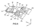
figure 6 est une vue en perspective d'une partie d'un deuxième mode de réalisation d'un dispositif d'accrochage selon la présente invention représenté de manière isolée, - la
figure 7 est une vue de dessus du dispositif de lafigure 6 avec les ferrures latérales et l'attache moteur arrière, - la
figure 8 est une vue en éclaté du dispositif de lafigure 7 , certains axes ayant été omis, - la
figure 9 est une vue en coupe selon le plan de coupe B-B de lafigure 7 .
- the
figure 1 is a partially schematic side view of an aircraft engine assembly, including an attachment pylon to which the present invention applies, - the
figure 2 is a perspective view of a first embodiment of an attachment device according to the present invention, - the
figure 3 is a top view of the device of thefigure 2 , - the
figure 4 is an exploded view of the device from thefigure 2 , some axes having been omitted, - the
figure 5 is a sectional view along the section plane AA of thefigure 3 , - the
figure 6 is a perspective view of a portion of a second embodiment of an attachment device according to the present invention shown in isolation, - the
figure 7 is a top view of the device of thefigure 6 with side fittings and rear engine mount, - the
figure 8 is an exploded view of the device from thefigure 7 , some axes having been omitted, - the
figure 9 is a sectional view along the section plane BB of thefigure 7 .
Dans la description qui va suivre, le terme « longitudinal » est à considérer par rapport à l'axe X.In the description that follows, the term "longitudinal" is to be considered with respect to the X axis.
En référence à la
Globalement, l'ensemble moteur 1 est composé d'un moteur tel qu'un turboréacteur 2 et du mât d'accrochage 4, ce dernier étant muni notamment d'une pluralité d'attaches moteur 6, 8, 9 et d'une structure rigide 10 portant ces mêmes attaches. A titre indicatif, il est noté que l'ensemble 1 est destiné à être entouré d'une nacelle (non représentée), et que le mât d'accrochage 4 comporte une autre série d'attaches (non représentées) permettant d'assurer la suspension de cet ensemble 1 sous la voilure de l'aéronef.Overall, the engine assembly 1 is composed of a motor such as a
Dans toute la description qui va suivre, par convention, on appelle X la direction longitudinale du mât 4 qui est également assimilable à la direction longitudinale du turboréacteur 2, cette direction X étant parallèle à un axe longitudinal 5 de ce turboréacteur 2. D'autre part, on appelle Y la direction orientée transversalement par rapport au mât 4 et également assimilable à la direction transversale du turboréacteur 2, et Z la direction verticale ou de la hauteur, ces trois directions X, Y et Z étant orthogonales entre-elles.Throughout the following description, by convention, X is the longitudinal direction of the mast 4 which is also comparable to the longitudinal direction of the
D'autre part, les termes « avant » et « arrière » sont à considérer par rapport à une direction d'avancement de l'aéronef rencontrée suite à la poussée exercée par le turboréacteur 2, cette direction étant représentée schématiquement par la flèche 7.On the other hand, the terms "front" and "rear" are to be considered in relation to a direction of advancement of the aircraft encountered following the thrust exerted by the
Sur la
La structure rigide 10 se présente quant à elle sous la forme classique d'un caisson formé par un longeron supérieur 18 et un longeron inférieur 20 s'étendant tous les deux selon la direction X et sensiblement dans un plan XY ou légèrement incliné par rapport à ce dernier, ainsi que par deux panneaux latéraux 22 (un seul étant visible sur la
D'autre part, le turboréacteur 2 dispose à l'avant d'un carter de soufflante 12 de grande dimension délimitant un canal annulaire de soufflante 14, et comporte vers l'arrière un carter central 16 de plus petite dimension, renfermant le coeur de ce turboréacteur. Enfin, le carter central 16 se prolonge vers l'arrière par un carter d'éjection 17 de plus grande dimension que celle du carter 16. Les carters 12, 16 et 17 sont bien entendu solidaires les uns des autres.On the other hand, the
Comme on peut l'apercevoir sur la
Sur la
Le dispositif d'accrochage comporte l'attache moteur arrière 8 et le dispositif de reprise des efforts de poussée 9 fixé sur l'attache moteur arrière 8.The attachment device comprises the
Le dispositif d'accrochage comporte un plan de symétrie P indiqué sur les
L'attache moteur arrière 8 comporte un corps formé d'une embase 32 destinée à être disposée du côté du longeron inférieur 20 formant l'extrémité inférieure du caisson 10.The
Le corps comporte également une ferrure support 34 sensiblement en forme d'arc de cercle fixé sous l'embase à l'opposé du longeron inférieur 20.The body also comprises a
De manière avantageuse, l'embase 32 et la ferrure support 34 sont réalisées d'une seule pièce en matériau métallique.Advantageously, the
La ferrure support 34 comporte une extrémité droite 34a et une extrémité gauche 34b reliées au moteur, plus particulièrement au carter de soufflante par des manilles 35a, 35b, auxquelles elles sont liées mécaniquement par des axes (non représentés). L'attache moteur arrière 8 forme alors, comme cela a été décrit précédemment, deux demi-attaches, une demi-attache droite 8a et une demi-attache gauche 8b.The support fitting 34 comprises a
L'attache moteur arrière 8 est fixée au caisson, par l'intermédiaire de deux ferrures latérales disposées de part du plan de symétrie du caisson et fixées par éclissage sur le caisson 10, une ferrure latérale droite 36a et une ferrure latérale gauche 36b.The
La droite et la gauche sont considérées par rapport au plan P et regardant de l'avant vers l'arrière, i.e. de l'attache 6 vers l'attache 8 sur la
Nous décrirons en détail la ferrure latérale droite 36a, la ferrure latérale gauche ayant la même structure. La ferrure latérale 36a comporte une première platine 38a contenue dans un plan XZ et une deuxième platine 40a disposée à angle droit dans un plan XY, la première platine 38a étant fixée par éclissage entre une aile latérale (non représentée) du longeron inferieur 20 contenue dans un plan XZ et un panneau latéral 22.We will describe in detail the right side fitting 36a, the left side fitting having the same structure. The lateral fitting 36a comprises a
La deuxième platine 38a est contenue dans un plan XY parallèle au longeron inférieur 20 à distance de celui-ci, permettant le montage de l'attache moteur arrière 8 sur les ferrures latérales, comme nous le verrons par la suite.The
L'embase 32 comporte, dans l'exemple représenté, en saillie de sa face 32a en regard d'une face inférieure du longeron inférieur 20, deux paires de pions 42, disposées chacune symétriquement de part d'autre du plan de symétrie P ; Les pions 42 de chaque paire sont alignés selon la direction X et comportent un alésage 44 de direction X.The
Il est bien entendu que le nombre de pions peut être supérieur à deux, que l'on pourrait prévoir plus d'une paire de pions de part et d'autre du plan de symétrie P.It is understood that the number of pions may be greater than two, that one could provide more than one pair of pions on either side of the plane of symmetry P.
Nous allons décrire la fixation de la paire de pions 42 gauche sur la ferrure latérale droite 36a.We will describe the attachment of the pair of
La ferrure latérale gauche 36a comporte deux lumières 46a pratiquées dans la deuxième platine 40a contenue dans le plan XY et disposées l'une par rapport l'autre de manière correspondante à la disposition des pions 42.The left side fitting 36a has two
Sur la
La paire de pions 42 sont montés dans la paire de lumières 46a pratiquée du côté d'une face inférieure de la deuxième platine 40a et débouche entre une face supérieure de la deuxième platine 40 et le longeron inférieur 20. Chaque alésage 44 des pions 42 reçoit un axe (non représenté) selon l'axe X.The pair of
L'embase 32 est fixée au caisson au moyen de vis de traction (non représentées), par exemple deux de chaque côté. Ces vis de traction permettent une reprise des efforts selon l'axe Z et une reprise du moment selon X.The
Les pions par l'intermédiaire des axes assurent la reprise des efforts selon l'axe Z de l'attache moteur arrière 8 sur le caisson en cas de rupture des vis de traction. En outre, les pions 42 sont montés avec jeu dans la platine 40, ainsi ils ne reprennent le moment selon X qu'en cas de rupture d'une ferrure latérale.The pins via the axles ensure the recovery of forces along the Z axis of the
La fixation de la paire de pions 42 droit sur la ferrure latérale gauche 36b est similaire à celle de la paire de pions gauche et ne sera donc pas décrite en détail.Fixing the pair of
Selon la présente invention, le dispositif de reprise des efforts de poussée comporte une ferrure de connexion 49 disposée entre l'embase 32 et le longeron inférieur 20 et fixée sur la face supérieure de l'embase 32 de manière symétrique par rapport au plan de symétrie P.According to the present invention, the thrust force recovery device comprises a connection fitting 49 disposed between the base 32 and the
De manière avantageuse, cette ferrure est doublée afin d'assurer la fonction « fail-safe ».Advantageously, this fitting is doubled to ensure the "fail-safe" function.
La ferrure de connexion est en fait composée d'une ferrure de connexion extérieure 50 et d'une ferrure de connexion intérieure 56 logée dans la ferrure de connexion extérieure 50.The connection fitting is in fact composed of an external connection fitting 50 and an internal connection fitting 56 housed in the external connection fitting 50.
La ferrure de connexion extérieure comporte un corps 51 munie des pattes de fixation 52 en saillie de sa périphérie, chacune munie d'au moins un alésage 54 pour la fixation sur l'embase 32 au moyen de vis de traction (non représentées). Dans l'exemple représenté, la ferrure comporte deux pattes latérales 52 munies d'un alésage 54 et une patte 52 en saillie d'une extrémité arrière de la ferrure de connexion 50 et munie de trois alésages 54.The external connection fitting comprises a
De manière avantageuse, des nervures de renfort 57 sont prévues entre les pattes de fixation 52 et le corps 51 de manière à augmenter la rigidité de la fixation.Advantageously, reinforcement ribs 57 are provided between the
On pourra prévoir de remplacer les pattes de fixation par une bride périphérique.It may be provided to replace the fastening tabs by a peripheral flange.
Le corps 51 comporte un alésage central 58 pour recevoir une première extrémité du pion de poussée 60 destiné à transmettre les efforts de poussée de la ferrure de connexion 50 au caisson, une deuxième extrémité du pion 60 étant montée dans le caisson 10.The
Le corps 51 s'étend vers l'avant par une platine 62 munie d'un alésage 64 recevant un axe 66 de connexion mécanique du palonnier 28.The
De manière avantageuse, la platine 62 est inclinée vers l'avant vers le bas sensiblement selon la direction des bielles 26.Advantageously, the
Le corps 51 de la ferrure de connexion 50 est délimité par des parois latérales, une paroi arrière et une paroi supérieure définissant un volume creux, et accueille la ferrure de connexion intérieure 56, formant ainsi une ferrure de connexion « fail-safe ».The
La ferrure de connexion intérieure 56 a sensiblement la même forme que la ferrure 50, elle comporte un corps 68 et des pattes latérales et arrière 70 prises en sandwich entre les pattes 52 et l'embase 32, et une platine 72 s'étendant vers l'avant parallèlement à la platine 62, munie d'un alésage 73 pour le passage de l'axe 66.The inner connection fitting 56 has substantially the same shape as the fitting 50, it comprises a
Le corps 68 comporte également un alésage 75 en regard de l'alésage 58 du corps 51 pour recevoir une extrémité du pion de poussée 60.The
Les deux platines 62, 72 s'étendent parallèlement à distance l'une de l'autre, délimitant un espace pour recevoir une partie du palonnier 28.The two
Une ferrure de connexion 49 simple, c'est-à-dire qui n'est pas composée de deux ferrures, ne sort bien entendu pas du cadre de la présente invention.A simple connection fitting 49, that is to say one which does not consist of two fittings, does not of course go outside the scope of the present invention.
De manière avantageuse et comme cela est particulièrement visible sur les
Dans l'exemple représenté, les première 28.1 et troisième 28.3 parties sont disposées respectivement au-dessus de la platine 62 et au-dessous de la platine 72, et la deuxième partie 28.2 est disposée dans l'espace ménagée entre les platines 62, 72. Ainsi la platine 62 est prise en sandwich entre la première 28.1 et la deuxième 28.2 partie du palonnier 28 et la platine 72 est prise en sandwich entre la deuxième 28.2 et troisième 28.3 partie du palonnier 28.In the example shown, the first 28.1 and third 28.3 parts are respectively disposed above the
De manière avantageuse, une empreinte 76 est réalisée en creux dans la face de la première partie 28.1 en contact avec la platine 62, et une empreinte 78 est réalisée en creux dans la face de la deuxième partie 28.2 en contact avec la platine 72. Ces empreintes 76, 78 permettent de réduire l'épaisseur du palonnier.Advantageously, a
En outre, ces empreintes 76, 78 ont une forme en V dont l'ouverture est orientée vers l'arrière de manière à permettre le pivotement du palonnier autour de l'axe 66 par rapport aux ferrures de connexion 50, 56.In addition, these
Selon la présente invention, en cas de rupture d'une bielle 26, le palonnier 28 vient en butée contre la ferrure latérale 36 du côté de la bielle 26 intacte, ce qui permet de ne pas utiliser de ferrure de butée supplémentaire.According to the present invention, in case of breakage of a connecting rod 26, the
Selon la présente invention, chaque ferrure latérale 36a, 36 comporte une portion 80 en saillie vers l'avant au niveau de la connexion entre la première 38a et la deuxième 40a platine se terminant par une plaque de butée 82 s'étendant sensiblement selon les directions Y et Z.According to the present invention, each lateral fitting 36a, 36 has a
Avantageusement, une nervure de renfort 84 est prévue sous la portion en saillie 80.Advantageously, a reinforcing
Nous allons maintenant décrire les chemins de reprise des efforts exercés selon les directions X, Y et Z par le dispositif selon la présente invention.We will now describe the paths of recovery of the forces exerted in directions X, Y and Z by the device according to the present invention.
En fonctionnement normal, lorsque toutes les pièces sont intactes comme cela est représenté sur la
Les efforts générés par le moteur et s'exerçant selon la direction X sont transmis des bielles 26 au palonnier 28 par les axes 29, puis du palonnier 28 aux ferrures de connexion 50, 56 par l'axe 29, puis des ferrures de connexion 50, 56 au caisson par le pion de poussée 60.The forces generated by the motor and acting in the direction X are transmitted from the connecting rods 26 to the
En cas de rupture de la bielle gauche, dans un fonctionnement « en mode reverse », lorsque le moteur exerce un effort vers l'avant, le palonnier 28 bascule autour de l'axe et vient en butée contre la plaque de butée 82 de la ferrure latérale droite 36a, les efforts sont alors transmis de la bielle droite 26a à la ferrure latérale droite 36a, puis de la ferrure latérale droite 36a au caisson 10.In case of breakage of the left rod, in a "reverse mode" operation, when the engine exerts a forward force, the
En cas de rupture de la bielle droite 26a, la ferrure latérale gauche reprend les efforts.In case of rupture of the
Selon l'application de l'effort, une partie plus ou moins grande de cet effort est reprise par le palonnier, l'axe 66 et la ferrure de connexion.Depending on the application of the force, a greater or lesser part of this force is taken up by the rudder, the
Lorsque le moteur exerce un effort de poussée, en cas de rupture de la bielle droite, le palonnier 28 bascule autour de l'axe et vient en butée contre la plaque de butée 82 de la ferrure latérale droite 36a, les efforts de poussée sont alors repris par la ferrure latérale gauche 36a.When the motor exerts a thrust force, in the event of breakage of the right connecting rod, the
Selon l'application de l'effort de poussée, une partie plus ou moins grande des efforts de poussée est reprise par le palonnier, l'axe 66 et la ferrure de connexion.Depending on the application of the thrust force, a greater or lesser part of the thrust forces is taken up by the rudder, the
En cas de rupture d'une des trois parties 28.1, 28.2, 28.3 du palonnier, les deux parties intactes transmettent les efforts des bielles 26a, 26b au pion de poussée 60.In case of breakage of one of the three parts 28.1, 28.2, 28.3 of the spreader, the two intact parts transmit the forces of the connecting
En cas de rupture de la ferrure de connexion extérieure 50, la ferrure de connexion intérieure 56 prend le relais et transmet les efforts du palonnier 28 au caisson 10 via l'axe de poussée 60.In case of breakage of the external connection fitting 50, the internal connection fitting 56 takes over and transmits the forces of the
En fonctionnement normal, le moment selon X est repris sur l'attache arrière par les vis de traction de chaque côté de l'attache. En cas de rupture d'une ou plusieurs vis de traction, le moment selon X est repris par les pions 42.In normal operation, the moment according to X is taken up on the rear attachment by the traction screws on each side of the fastener. In case of rupture of one or more traction screws, the moment according to X is taken up by the
Les moments selon Y et selon Z sont repris à la fois par l'attache moteur arrière et l'attache moteur avant.The moments according to Y and Z are taken up by both the rear engine attachment and the front engine attachment.
De manière avantageuse, l'axe 60 est du type « fail-safe », i.e. il est double, celui-ci comporte, comme on peut le voir sur la
De manière avantageuse, l'axe 66 est du type « fail-safe », i.e. il est double, celui-ci comporte un axe extérieur et un axe intérieur, ainsi en cas de rupture de l'axe extérieur, l'axe intérieur prend le relais.Advantageously, the
Sur la
A des fins de simplification, les éléments ayant sensiblement la même forme et la même fonction que dans le premier mode de réalisation seront désignés par les mêmes références.For the purpose of simplification, the elements having substantially the same shape and the same function as in the first embodiment will be designated by the same references.
La fixation de l'attache moteur arrière étant similaire à celle du premier mode de réalisation, la description faite en relation avec le premier mode de réalisation s'applique.Fixing the rear engine attachment being similar to that of the first embodiment, the description made in connection with the first embodiment applies.
Selon ce deuxième mode de réalisation, la connexion mécanique entre le palonnier 128 et le caisson 10 est réalisée par une ferrure de connexion 149, avantageusement réalisée par deux ferrures de connexions emboîtées l'une dans l'autre, une ferrure extérieure 150 et une ferrure intérieure 152.According to this second embodiment, the mechanical connection between the
La ferrure extérieure 150 comporte un corps 151 bordé latéralement et vers l'arrière par une bride de fixation 161 percée d'alésages 154 pour permettre la fixation de la première ferrure 150 sur l'embase 32 au moyen de vis de traction (non représentées).The
On pourrait envisager comme dans le premier mode de réalisation, de prévoir des pattes de fixation.One could envisage as in the first embodiment, to provide fixing lugs.
Le corps 151 est délimité par deux parois latérales 153, une paroi supérieure 155, une paroi arrière 157, et une paroi avant 159.The
Le corps 151 comporte également un alésage 160 sensiblement au centre de sa paroi supérieure 155 pour recevoir une extrémité d'un pion de poussée 60.The
La ferrure de connexion extérieure 150 comporte également une chape 162 s'étendant de la paroi avant 159, cette chape recevant le palonnier 128.The external connection fitting 150 also comprises a
La chape 162 est inclinée vers l'avant vers le bas sensiblement selon la direction d'inclinaison des bielles 26a, 26b.The
La chape 162 est percée d'un alésage 164 recevant un axe 166.
La paroi avant 159 est percée pour permettre le passage d'une platine 168 de la deuxième ferrure 152.The
La ferrure intérieure 152 comporte un corps 170 de forme et de dimensions apte à pénétrer dans le corps 151 de la première ferrure 150 et la platine 168 en saillie d'une face avant du corps 170.The
Le corps 170 comporte une bride périphérique 172 également percée d'alésages correspondant à ceux de la bride 156 de la ferrure extérieure 150 et s'interposant entre la bride 156 de la ferrure extérieure et l'embase 32.The
Le corps 170 comporte un alésage 171 en regard de l'alésage 160 du corps 151 pour recevoir l'extrémité de l'axe de poussée 60.The
La platine 168 comporte un alésage 169 en regard de ceux de la chape 162 pour le passage de l'axe 166.The
Lors de la mise en place de la ferrure intérieure 152 dans la ferrure extérieure 150, la platine traverse la paroi avant 159 du corps 151 de la ferrure de connexion extérieure 150 et vient se loger entre les deux branches de la chape 162, comme cela est particulièrement visible sur la
La platine 168 s'étend parallèlement aux branches de la chape 162 et à distance de celles-ci, ménageant ainsi deux espaces.The
Une ferrure de connexion 149 simple, c'est-à-dire qui n'est pas composée de deux ferrures, ne sort bien entendu pas du cadre de la présente invention.A simple connection fitting 149, that is to say which is not composed of two fittings, does not of course go beyond the scope of the present invention.
De manière avantageuse, le palonnier 128 est formé de deux palonniers 128.1, 128.2 pénétrant respectivement dans les espaces ménagés entre la chape 162 et la platine 168.Advantageously, the
Ainsi en cas de rupture de l'un des palonniers 128.1, 128.2, l'autre palonnier prend le relais pour transmettre les efforts.Thus in the event of breakage of one of the lifters 128.1, 128.2, the other lifter takes over to transmit the efforts.
Les deux palonniers 128.1, 128.2 sont de forme similaire et comportent avantageusement une empreinte 178, 180 sur leur face en contact avec la platine 168 pour recevoir cette platine 168.The two spreaders 128.1, 128.2 are of similar shape and advantageously comprise a
Chaque palonnier 128.1, 128.2 comporte deux alésages latéraux pour la connexion aux bielles 26a, 26b et un alésage central pour la connexion aux ferrures de connexion 150, 152.Each lifter 128.1, 128.2 has two lateral bores for connection to connecting
Les empreintes 178, 180 ont une forme de V dont l'ouverture est orientée vers l'arrière, permettant le pivotement du palonnier autour de l'axe 168.The
Selon la présente invention et de manière similaire au premier mode de réalisation, chaque ferrure latérale 36a comporte une portion 80 en saillie vers l'avant au niveau de la connexion entre la première 38a et la deuxième 40a platine se terminant par une plaque de butée 82 s'étendant sensiblement selon les directions Y et Z.According to the present invention and similarly to the first embodiment, each lateral fitting 36a has a
Avantageusement, une nervure de renfort 84 est prévue sous la portion en saillie 80.Advantageously, a reinforcing
Les empreintes 178, 180 autorisent un angle de rotation suffisant pour permettre au palonnier de venir en butée contre l'une des portions 80 en saillie des ferrures latérales.The
Nous allons maintenant décrire les chemins de reprise des efforts exercés selon les directions X, Y et Z par le dispositif selon le deuxième mode de réalisation de la présente invention.We will now describe the paths of recovery of the forces exerted in directions X, Y and Z by the device according to the second embodiment of the present invention.
En fonctionnement normal, lorsque toutes les pièces sont intactes comme représentées sur la
En cas de rupture de la bielle gauche, dans un fonctionnement « en mode reverse », lorsque le moteur exerce un effort vers l'avant, le palonnier 128 bascule autour de l'axe et vient en butée contre la plaque de butée 82 de la ferrure latérale droite 36a, les efforts sont alors transmis de la bielle droite 26a à la ferrure latérale droite 36a, puis de la ferrure latérale droite 36a au caisson 10.In case of breakage of the left rod, in a "reverse mode" operation, when the engine exerts a forward force, the
En cas de rupture de la bielle droite 26a, la ferrure latérale gauche reprend les efforts.In case of rupture of the
Selon l'application de l'effort, une partie plus ou moins grande de cet effort est reprise par le palonnier, l'axe 66 et la ferrure de connexion.Depending on the application of the force, a greater or lesser part of this force is taken up by the rudder, the
Lorsque le moteur exerce un effort de poussée, en cas de rupture de la bielle droite, le palonnier 128 bascule autour de l'axe et vient en butée contre la plaque de butée 82 de la ferrure latérale droite 36a, les efforts de poussée sont alors repris par la ferrure latérale gauche 36a.When the motor exerts a thrust force, in case of breakage of the right rod, the
Selon l'application de l'effort de poussée, une partie plus ou moins grande des efforts de poussée est reprise par le palonnier, l'axe 66 et la ferrure de connexion.Depending on the application of the thrust force, a greater or lesser part of the thrust forces is taken up by the rudder, the
En cas de rupture d'un des deux palonniers 128.1, 128.2, l'autre palonnier transmet les efforts de poussée transmis par les bielles 26a, 26b au pion de poussée 60.In the event of rupture of one of the two spreaders 128.1, 128.2, the other spreader transmits the thrust forces transmitted by the connecting
En cas de rupture de la ferrure de connexion extérieure 150, la ferrure de connexion intérieure 152 prend le relais et transmet les efforts du palonnier 128 au caisson 10 via l'axe de poussée 60.In case of breakage of the external connection fitting 150, the internal connection fitting 152 takes over and transmits the forces of the
En fonctionnement normal, le moment selon X est repris sur l'attache arrière par les vis de traction de chaque côté de l'attache. En cas de rupture d'une ou plusieurs vis de traction, le moment selon X est repris par les pions 42.In normal operation, the moment according to X is taken up on the rear attachment by the traction screws on each side of the fastener. In case of rupture of one or more traction screws, the moment according to X is taken up by the
Les moments selon Y et selon Z sont repris à la fois par l'attache moteur arrière et l'attache moteur avant.The moments according to Y and Z are taken up by both the rear engine attachment and the front engine attachment.
Comme dans le premier mode de réalisation, l'axe 60 est avantageusement du type « fail-safe », i.e. il est double, celui-ci comporte comme on peut le voir sur les
De même, l'axe 166 est avantageusement du type « fail-safe », i.e. il est double, celui-ci comporte un axe extérieur et un axe intérieur, ainsi en cas de rupture de l'axe extérieur, l'axe intérieur prend le relais.Similarly, the
Les dispositifs de reprise des efforts représentés sur les
La ferrure de connexion 49 est du type fail-safe et comporte en fait deux ferrures 50, 56 l'une dans l'autre, l'axe 66 entre le palonnier et cette ferrure est monté sans jeu dans les deux ferrures (
Claims (10)
- Aircraft engine attachment device comprising a rigid structure (10) and means for attaching said engine on said rigid structure, in which said attachment means comprise a rear engine attachment (8) and a device (9) for taking up thrust forces generated by the engine, in which the rear engine attachment (8) is attached to the rigid structure by means of two lateral fittings attached to the rigid structure, in which said force take-up device (9) comprises two connecting rods (26a, 26b) mechanically connected to a spreader beam (28, 128) by a mechanical connection, a connection fitting (49, 149) attached to the rear engine attachment (8) and mechanically connected to the rigid structure (10) by a thrust pin (60), in which the spreader beam is mechanically connected to the connection fitting and the lateral fittings comprise stop means intended to limit the pivoting of the spreader beam (28) if a connecting rod (26a, 26b) breaks and ensuring the transmission of thrust forces generated by the engine to the rigid structure (10).
- Attachment device according to claim 1, in which the connection fitting comprises an external fitting (50, 150) and an internal fitting (56, 152).
- Device according to claim 2, in which the external fitting (50) comprises a hollow body (51) and a plate extending toward the front of said casing and the internal fitting (56) comprises a body housed in the hollow body (51) of the external fitting (50)
and comprising a plate extending forward from the body parallel to the first plate, in which the two plates form a clevis mounting to which the spreader beam (28) is mechanically connected. - Attachment device according to the previous claim, in which the spreader beam (28) comprises a first (28.1) and a third (28.3) portion forming a clevis mounting and surrounding the clevis mounting of the connection fitting (49) and a second portion (28.2) inserted between the first (28.1) and the third (28.3) portions, in which said second portion (28.2) penetrates the clevis mounting of the connection fitting (49).
- Attachment device according to claim 2, in which the external fitting (150) comprises a body (151) formed by a casing without a base, and a clevis mounting (162) extends forward from a front wall of the casing; said front wall (159) comprises a hole enabling communication between the inside of the casing and the space between the branches of the clevis mounting (162), and the internal fitting (152) comprises a body (171) housed in the body of the external fitting (150) and a plate (168) passing through the hole of the front wall (159) and housed between the branches of the clevis mounting (162), the spreader beam (128) comprises two portions (1.28.1, 128.2) forming a clevis mounting; said clevis mounting receives the plate (168) of the internal fitting (152) and is received in the clevis mounting (162) of the external fitting (150).
- Attachment device according to one of claims 3 to 5, in which the bodies (51, 151) of the external (50, 150) and internal (56, 152) fittings each comprise means for peripheral attachment (52, 70, 161, 172) to the rear engine attachment (8) by tension bolts, in which the means (70, 172) for attaching the internal fitting (56, 152) are clamped between the means (52, 161) for attaching the external fitting (50, 150) and the rear engine attachment (8).
- Attachment device according to one of claims 1 to 6, in which each lateral fitting (36a) comprises a first plate (38a) attached by fishplating to the rigid structure (10) and a second plate (40a) orthogonal to the first plate (38a) and substantially parallel to a lower spar (20) of the rigid structure (10), in which the rear engine attachment (8) comprises a base (32) attached by tension bolts to the rigid structure.
- Attachment device according to claim 7, in which said second plate (40a) comprises at least two holes, in which the base (32) is equipped with projecting pins (42), said pins (42) comprise bores orthogonal to their axis, the pins (42) pass through the second plate (40a) by way of said holes and an internal pin is mounted in each bore of the pins (42).
- Engine assembly including an engine and an engine attachment device, in which said attachment device is a device according to any one of the previous claims.
- Aircraft comprising at least one engine assembly according to claim 9, assembled on a wing or on a rear portion of the fuselage of said aircraft.
Applications Claiming Priority (2)
| Application Number | Priority Date | Filing Date | Title |
|---|---|---|---|
| FR0757166A FR2920138B1 (en) | 2007-08-24 | 2007-08-24 | AIRCRAFT ENGINE HANDLING DEVICE HAVING A REDUCED GAPPING EFFORTS RECOVERY DEVICE |
| PCT/EP2008/061010 WO2009027333A1 (en) | 2007-08-24 | 2008-08-22 | Device for attaching an aircraft engine including a thrust force collection device with reduced overall dimensions |
Publications (2)
| Publication Number | Publication Date |
|---|---|
| EP2181037A1 EP2181037A1 (en) | 2010-05-05 |
| EP2181037B1 true EP2181037B1 (en) | 2012-06-20 |
Family
ID=39356550
Family Applications (1)
| Application Number | Title | Priority Date | Filing Date |
|---|---|---|---|
| EP08787412A Active EP2181037B1 (en) | 2007-08-24 | 2008-08-22 | Device for attaching an aircraft engine including a thrust force collection device with reduced overall dimensions |
Country Status (9)
| Country | Link |
|---|---|
| US (1) | US8256708B2 (en) |
| EP (1) | EP2181037B1 (en) |
| JP (1) | JP5421263B2 (en) |
| CN (1) | CN101784442B (en) |
| BR (1) | BRPI0815704A2 (en) |
| CA (1) | CA2696802C (en) |
| FR (1) | FR2920138B1 (en) |
| RU (1) | RU2472676C2 (en) |
| WO (1) | WO2009027333A1 (en) |
Families Citing this family (29)
| Publication number | Priority date | Publication date | Assignee | Title |
|---|---|---|---|---|
| FR2915175B1 (en) * | 2007-04-20 | 2009-07-17 | Airbus France Sa | ENGINE ATTACHING MACHINE FOR AN AIRCRAFT HAVING A REAR ENGINE ATTACHMENT BEAM DEPORTEE FROM THE HOUSING |
| FR2918644B1 (en) * | 2007-07-09 | 2009-10-23 | Airbus France Sas | ENGINE ATTACHING MACHINE FOR AN AIRCRAFT HAVING A FOUR-POINT ARTICULATED HINGE. |
| US8511605B2 (en) | 2008-06-02 | 2013-08-20 | United Technologies Corporation | Gas turbine engine with low stage count low pressure turbine |
| US20140174056A1 (en) | 2008-06-02 | 2014-06-26 | United Technologies Corporation | Gas turbine engine with low stage count low pressure turbine |
| US8128021B2 (en) * | 2008-06-02 | 2012-03-06 | United Technologies Corporation | Engine mount system for a turbofan gas turbine engine |
| US8807477B2 (en) | 2008-06-02 | 2014-08-19 | United Technologies Corporation | Gas turbine engine compressor arrangement |
| US8695920B2 (en) | 2008-06-02 | 2014-04-15 | United Technologies Corporation | Gas turbine engine with low stage count low pressure turbine |
| US8800914B2 (en) | 2008-06-02 | 2014-08-12 | United Technologies Corporation | Gas turbine engine with low stage count low pressure turbine |
| GB0810585D0 (en) * | 2008-06-11 | 2008-07-16 | Rolls Royce Plc | Engine mounting arrangement |
| FR2948635B1 (en) * | 2009-07-31 | 2011-08-26 | Airbus Operations Sas | AIRCRAFT ASSEMBLY COMPRISING A TURBOMACHINE HANDLING MACHINE HAVING THE ATTACHING MEANS ON THE SAIL |
| DE102009054568A1 (en) | 2009-12-11 | 2011-06-16 | Rolls-Royce Deutschland Ltd & Co Kg | Device for suspending a jet engine on a support structure |
| FR2959210B1 (en) | 2010-04-21 | 2013-08-23 | Snecma | AIRCRAFT TURBOELECTOR SUSPENSION PUSH RIDER AND SUSPENSION WITH BLOWER HOUSING THUS EQUIPPED |
| FR2961172B1 (en) * | 2010-06-14 | 2012-07-27 | Snecma | SUSPENSION OF A TURBOMOTOR OR THE LIKE TO AN AIRCRAFT PYLON WITH INTEGRATED SAFETY. |
| FR2962976B1 (en) * | 2010-07-22 | 2013-07-26 | Airbus Operations Sas | CONNECTING DEVICE FOR CONNECTING A FIRST BODY TO A SECOND BODY, IN PARTICULAR FOR AN AIRCRAFT ENGINE ASSEMBLY |
| FR2965549B1 (en) * | 2010-10-01 | 2013-07-05 | Airbus Operations Sas | ROPE RESTRAINT DEVICE FOR AN AIRCRAFT ENGINE HITCHING MACHINE, INTEGRATING THREE ALIGNED ROTORS |
| FR2969578B1 (en) * | 2010-12-27 | 2013-02-08 | Snecma | DEVICE FOR SUSPENDING A TURBOJET ENGINE |
| FR2973345B1 (en) * | 2011-03-29 | 2013-04-05 | Airbus | DEVICE FOR THE INSTALLATION AND REMOVAL OF A PRE-COOLER FROM AN AIRCRAFT ENGINE |
| CN103032434B (en) * | 2012-11-26 | 2016-05-04 | 中国商用飞机有限责任公司 | Fail safety safety plug |
| FR3000529B1 (en) * | 2012-12-28 | 2015-03-06 | Airbus Operations Sas | FLEXIBLE BONDING DEVICE FOR AN AIRCRAFT PROPULSIVE ASSEMBLY |
| FR3002288B1 (en) * | 2013-02-20 | 2022-11-25 | Snecma | SUSPENSION OF A TURBOJET BY DOUBLE REAR SUPPORT |
| US10371047B2 (en) | 2013-10-16 | 2019-08-06 | United Technologies Corporation | Geared turbofan engine with targeted modular efficiency |
| FR3015434B1 (en) * | 2013-12-23 | 2017-12-08 | Snecma | TURBOMACHINE SUSPENSION |
| CN110182373B (en) * | 2015-01-07 | 2023-01-10 | 洛德公司 | Bearing assembly for aircraft engine mount |
| FR3041935B1 (en) * | 2015-10-05 | 2017-12-15 | Airbus Operations Sas | AIRCRAFT ENGINE ASSEMBLY COMPRISING AT LEAST TWO REAR ENGINE FASTENERS AXIALLY SHIFTED FROM EACH OTHER |
| FR3069848B1 (en) * | 2017-08-02 | 2019-08-30 | Airbus | LOW PRIMARY STRUCTURE FOR AN AIRCRAFT ENGINE HITCHING MAT |
| EP3663206B1 (en) * | 2018-12-06 | 2023-09-06 | AIRBUS HELICOPTERS DEUTSCHLAND GmbH | An attachment for suspending an aircraft engine |
| US11479104B2 (en) | 2019-07-24 | 2022-10-25 | Honeywell International Inc. | System and method for gas turbine engine mount with seal |
| FR3128205A1 (en) * | 2021-10-14 | 2023-04-21 | Airbus Operations | ASSEMBLING A MAST WITH AN AIRCRAFT ENGINE |
| CN113859553A (en) * | 2021-11-18 | 2021-12-31 | 中国商用飞机有限责任公司 | Aircraft hanging interface assembly and aircraft hanging |
Family Cites Families (19)
| Publication number | Priority date | Publication date | Assignee | Title |
|---|---|---|---|---|
| US5320307A (en) * | 1992-03-25 | 1994-06-14 | General Electric Company | Aircraft engine thrust mount |
| US5725181A (en) * | 1996-05-01 | 1998-03-10 | The Boeing Company | Aircraft engine thrust mount |
| US5873547A (en) * | 1997-05-20 | 1999-02-23 | The Boeing Company | Aircraft engine thrust mount |
| US6189830B1 (en) * | 1999-02-26 | 2001-02-20 | The Boeing Company | Tuned engine mounting system for jet aircraft |
| FR2799432A1 (en) * | 1999-10-07 | 2001-04-13 | Snecma | SUSPENSION WITH INTEGRATED SAFETY FOR AIRCRAFT PUMP GROUPS |
| FR2806699B1 (en) * | 2000-03-22 | 2002-05-10 | Aerospatiale Matra Airbus | PUSH RETURN DEVICE CAPABLE OF CONNECTING A TURBOMOTOR AND AN AIRCRAFT MAT |
| FR2828167B1 (en) * | 2001-07-31 | 2003-11-21 | Airbus France | DEVICE FOR HANGING AN ENGINE ON AN AIRCRAFT |
| DE10249517B4 (en) * | 2002-10-23 | 2008-11-20 | Eurocopter Deutschland Gmbh | Shock-absorbing, load-limiting connection device and rotary wing aircraft with such a connection device |
| JP3953409B2 (en) * | 2002-10-31 | 2007-08-08 | スネクマ | Jet engine suspension |
| FR2855496B1 (en) * | 2003-05-27 | 2006-09-22 | Snecma Moteurs | REAR SUSPENSION OF AIRCRAFT ENGINE WITH PUSH REPEAT |
| FR2856656B1 (en) * | 2003-06-30 | 2006-12-01 | Snecma Moteurs | AIRCRAFT ENGINE REAR SUSPENSION WITH BOOMERANG SHAFT AND BOOMERANG SHAFT |
| RU2252176C1 (en) * | 2003-11-27 | 2005-05-20 | Открытое акционерное общество "Туполев" (ОАО "Туполев") | Fastening assembly of a flying vehicle's aviation engine |
| FR2883839B1 (en) * | 2005-03-29 | 2007-06-29 | Snecma Moteurs Sa | REAR SUSPENSION OF TURBOREACTOR |
| FR2887851B1 (en) * | 2005-06-29 | 2007-08-17 | Airbus France Sas | ENGINE ATTACHING MAT FOR AN AIRCRAFT |
| FR2887850B1 (en) * | 2005-06-29 | 2008-11-07 | Airbus France Sas | APPARATUS FOR CONNECTING AN ENGINE INTERPOSED BETWEEN AN AIRCRAFT SAIL AND THIS ENGINE |
| FR2891244B1 (en) * | 2005-09-26 | 2009-04-03 | Airbus France Sas | ENGINE ATTACHING MAT FOR AN AIRCRAFT |
| FR2891251B1 (en) * | 2005-09-28 | 2009-04-03 | Airbus France Sas | ENGINE ATTACHING MAT FOR AN AIRCRAFT |
| FR2903382B1 (en) * | 2006-07-10 | 2008-10-10 | Airbus France Sas | DEVICE FOR HITCHING AN AIRCRAFT ENGINE COMPRISING TWO PIVOT RETRACTORS WITH EMBOITEMENT TRANSVERSE |
| FR2914908B1 (en) | 2007-04-13 | 2009-10-30 | Airbus France Sa | APPARATUS FOR ATTACHING AN AIRCRAFT ENGINE AND AIRCRAFT HAVING AT LEAST ONE SUCH DEVICE. |
-
2007
- 2007-08-24 FR FR0757166A patent/FR2920138B1/en not_active Expired - Fee Related
-
2008
- 2008-08-22 WO PCT/EP2008/061010 patent/WO2009027333A1/en active Application Filing
- 2008-08-22 EP EP08787412A patent/EP2181037B1/en active Active
- 2008-08-22 RU RU2010111152/11A patent/RU2472676C2/en not_active IP Right Cessation
- 2008-08-22 CA CA2696802A patent/CA2696802C/en active Active
- 2008-08-22 BR BRPI0815704-9A2A patent/BRPI0815704A2/en not_active IP Right Cessation
- 2008-08-22 JP JP2010521438A patent/JP5421263B2/en not_active Expired - Fee Related
- 2008-08-22 US US12/674,555 patent/US8256708B2/en active Active
- 2008-08-22 CN CN200880104237.7A patent/CN101784442B/en active Active
Also Published As
| Publication number | Publication date |
|---|---|
| US8256708B2 (en) | 2012-09-04 |
| CN101784442A (en) | 2010-07-21 |
| EP2181037A1 (en) | 2010-05-05 |
| US20110114786A1 (en) | 2011-05-19 |
| CA2696802C (en) | 2015-11-24 |
| JP5421263B2 (en) | 2014-02-19 |
| JP2010536643A (en) | 2010-12-02 |
| CA2696802A1 (en) | 2009-03-05 |
| FR2920138B1 (en) | 2010-03-12 |
| WO2009027333A1 (en) | 2009-03-05 |
| RU2010111152A (en) | 2011-09-27 |
| CN101784442B (en) | 2013-10-09 |
| BRPI0815704A2 (en) | 2015-02-10 |
| RU2472676C2 (en) | 2013-01-20 |
| FR2920138A1 (en) | 2009-02-27 |
Similar Documents
| Publication | Publication Date | Title |
|---|---|---|
| EP2181037B1 (en) | Device for attaching an aircraft engine including a thrust force collection device with reduced overall dimensions | |
| EP2142430B1 (en) | Aircraft engine mounting device and aircraft including at least one such device | |
| EP2170704B1 (en) | Device for coupling an aircraft engine and method for mounting an aircraft engine by means of such a device | |
| EP2167384B1 (en) | Pylon for coupling an engine for an aircraft having a rear engine attachment beam forming a rudder control bar | |
| EP2137072B1 (en) | Device for attaching an aircraft engine and aircraft comprising at least one such device | |
| EP2139768B1 (en) | Aircraft engine attachment pylon that has an engine rear attachment fitted with a barrel nut | |
| EP2150462B1 (en) | Aircraft engine coupling pylon comprising a slanting spacer for fastening the front engine attachment | |
| EP1896327B1 (en) | Engine mounting structure for an aircraft | |
| EP2018322B1 (en) | Device for attaching an aircraft engine | |
| EP1896325B1 (en) | Engine mounting structure for an aircraft | |
| FR2891244A1 (en) | ENGINE ATTACHING MAT FOR AN AIRCRAFT | |
| WO2009147341A2 (en) | Engine mounting pylon including means for attaching spars and panels arranged outside the inner space of the box | |
| WO2006021721A1 (en) | Aircraft engine unit | |
| EP1931568A1 (en) | Rigid framework for aircraft engine mounting structure and engine mounting structure comprising same | |
| EP1896326A1 (en) | Engine mount for an aircraft, to be placed between an engine and an engine mounting structure | |
| FR2887522A1 (en) | Aircraft shipset, has turboshaft engine fixing mast with units to fix box forming rigid structure under box forming aerofoil unit, where fixing units have fastener with insert fitting placed inside structure and box forming aerofoil unit |
Legal Events
| Date | Code | Title | Description |
|---|---|---|---|
| PUAI | Public reference made under article 153(3) epc to a published international application that has entered the european phase |
Free format text: ORIGINAL CODE: 0009012 |
|
| 17P | Request for examination filed |
Effective date: 20100218 |
|
| AK | Designated contracting states |
Kind code of ref document: A1 Designated state(s): AT BE BG CH CY CZ DE DK EE ES FI FR GB GR HR HU IE IS IT LI LT LU LV MC MT NL NO PL PT RO SE SI SK TR |
|
| AX | Request for extension of the european patent |
Extension state: AL BA MK RS |
|
| GRAP | Despatch of communication of intention to grant a patent |
Free format text: ORIGINAL CODE: EPIDOSNIGR1 |
|
| DAX | Request for extension of the european patent (deleted) | ||
| GRAS | Grant fee paid |
Free format text: ORIGINAL CODE: EPIDOSNIGR3 |
|
| GRAA | (expected) grant |
Free format text: ORIGINAL CODE: 0009210 |
|
| AK | Designated contracting states |
Kind code of ref document: B1 Designated state(s): AT BE BG CH CY CZ DE DK EE ES FI FR GB GR HR HU IE IS IT LI LT LU LV MC MT NL NO PL PT RO SE SI SK TR |
|
| REG | Reference to a national code |
Ref country code: GB Ref legal event code: FG4D Free format text: NOT ENGLISH |
|
| REG | Reference to a national code |
Ref country code: CH Ref legal event code: EP |
|
| REG | Reference to a national code |
Ref country code: AT Ref legal event code: REF Ref document number: 562920 Country of ref document: AT Kind code of ref document: T Effective date: 20120715 |
|
| REG | Reference to a national code |
Ref country code: IE Ref legal event code: FG4D Free format text: LANGUAGE OF EP DOCUMENT: FRENCH |
|
| REG | Reference to a national code |
Ref country code: DE Ref legal event code: R096 Ref document number: 602008016538 Country of ref document: DE Effective date: 20120816 |
|
| PG25 | Lapsed in a contracting state [announced via postgrant information from national office to epo] |
Ref country code: FI Free format text: LAPSE BECAUSE OF FAILURE TO SUBMIT A TRANSLATION OF THE DESCRIPTION OR TO PAY THE FEE WITHIN THE PRESCRIBED TIME-LIMIT Effective date: 20120620 Ref country code: NO Free format text: LAPSE BECAUSE OF FAILURE TO SUBMIT A TRANSLATION OF THE DESCRIPTION OR TO PAY THE FEE WITHIN THE PRESCRIBED TIME-LIMIT Effective date: 20120920 Ref country code: LT Free format text: LAPSE BECAUSE OF FAILURE TO SUBMIT A TRANSLATION OF THE DESCRIPTION OR TO PAY THE FEE WITHIN THE PRESCRIBED TIME-LIMIT Effective date: 20120620 Ref country code: SE Free format text: LAPSE BECAUSE OF FAILURE TO SUBMIT A TRANSLATION OF THE DESCRIPTION OR TO PAY THE FEE WITHIN THE PRESCRIBED TIME-LIMIT Effective date: 20120620 |
|
| REG | Reference to a national code |
Ref country code: NL Ref legal event code: VDEP Effective date: 20120620 |
|
| REG | Reference to a national code |
Ref country code: AT Ref legal event code: MK05 Ref document number: 562920 Country of ref document: AT Kind code of ref document: T Effective date: 20120620 |
|
| REG | Reference to a national code |
Ref country code: LT Ref legal event code: MG4D Effective date: 20120620 |
|
| PG25 | Lapsed in a contracting state [announced via postgrant information from national office to epo] |
Ref country code: GR Free format text: LAPSE BECAUSE OF FAILURE TO SUBMIT A TRANSLATION OF THE DESCRIPTION OR TO PAY THE FEE WITHIN THE PRESCRIBED TIME-LIMIT Effective date: 20120921 Ref country code: LV Free format text: LAPSE BECAUSE OF FAILURE TO SUBMIT A TRANSLATION OF THE DESCRIPTION OR TO PAY THE FEE WITHIN THE PRESCRIBED TIME-LIMIT Effective date: 20120620 Ref country code: SI Free format text: LAPSE BECAUSE OF FAILURE TO SUBMIT A TRANSLATION OF THE DESCRIPTION OR TO PAY THE FEE WITHIN THE PRESCRIBED TIME-LIMIT Effective date: 20120620 Ref country code: HR Free format text: LAPSE BECAUSE OF FAILURE TO SUBMIT A TRANSLATION OF THE DESCRIPTION OR TO PAY THE FEE WITHIN THE PRESCRIBED TIME-LIMIT Effective date: 20120620 |
|
| PG25 | Lapsed in a contracting state [announced via postgrant information from national office to epo] |
Ref country code: AT Free format text: LAPSE BECAUSE OF FAILURE TO SUBMIT A TRANSLATION OF THE DESCRIPTION OR TO PAY THE FEE WITHIN THE PRESCRIBED TIME-LIMIT Effective date: 20120620 Ref country code: CY Free format text: LAPSE BECAUSE OF FAILURE TO SUBMIT A TRANSLATION OF THE DESCRIPTION OR TO PAY THE FEE WITHIN THE PRESCRIBED TIME-LIMIT Effective date: 20120620 Ref country code: CZ Free format text: LAPSE BECAUSE OF FAILURE TO SUBMIT A TRANSLATION OF THE DESCRIPTION OR TO PAY THE FEE WITHIN THE PRESCRIBED TIME-LIMIT Effective date: 20120620 Ref country code: RO Free format text: LAPSE BECAUSE OF FAILURE TO SUBMIT A TRANSLATION OF THE DESCRIPTION OR TO PAY THE FEE WITHIN THE PRESCRIBED TIME-LIMIT Effective date: 20120620 Ref country code: EE Free format text: LAPSE BECAUSE OF FAILURE TO SUBMIT A TRANSLATION OF THE DESCRIPTION OR TO PAY THE FEE WITHIN THE PRESCRIBED TIME-LIMIT Effective date: 20120620 Ref country code: SK Free format text: LAPSE BECAUSE OF FAILURE TO SUBMIT A TRANSLATION OF THE DESCRIPTION OR TO PAY THE FEE WITHIN THE PRESCRIBED TIME-LIMIT Effective date: 20120620 Ref country code: IS Free format text: LAPSE BECAUSE OF FAILURE TO SUBMIT A TRANSLATION OF THE DESCRIPTION OR TO PAY THE FEE WITHIN THE PRESCRIBED TIME-LIMIT Effective date: 20121020 |
|
| BERE | Be: lapsed |
Owner name: AIRBUS OPERATIONS Effective date: 20120831 |
|
| PG25 | Lapsed in a contracting state [announced via postgrant information from national office to epo] |
Ref country code: PT Free format text: LAPSE BECAUSE OF FAILURE TO SUBMIT A TRANSLATION OF THE DESCRIPTION OR TO PAY THE FEE WITHIN THE PRESCRIBED TIME-LIMIT Effective date: 20121022 Ref country code: PL Free format text: LAPSE BECAUSE OF FAILURE TO SUBMIT A TRANSLATION OF THE DESCRIPTION OR TO PAY THE FEE WITHIN THE PRESCRIBED TIME-LIMIT Effective date: 20120620 Ref country code: IT Free format text: LAPSE BECAUSE OF FAILURE TO SUBMIT A TRANSLATION OF THE DESCRIPTION OR TO PAY THE FEE WITHIN THE PRESCRIBED TIME-LIMIT Effective date: 20120620 |
|
| REG | Reference to a national code |
Ref country code: CH Ref legal event code: PL |
|
| PG25 | Lapsed in a contracting state [announced via postgrant information from national office to epo] |
Ref country code: NL Free format text: LAPSE BECAUSE OF FAILURE TO SUBMIT A TRANSLATION OF THE DESCRIPTION OR TO PAY THE FEE WITHIN THE PRESCRIBED TIME-LIMIT Effective date: 20120620 Ref country code: MC Free format text: LAPSE BECAUSE OF NON-PAYMENT OF DUE FEES Effective date: 20120831 |
|
| PLBE | No opposition filed within time limit |
Free format text: ORIGINAL CODE: 0009261 |
|
| STAA | Information on the status of an ep patent application or granted ep patent |
Free format text: STATUS: NO OPPOSITION FILED WITHIN TIME LIMIT |
|
| PG25 | Lapsed in a contracting state [announced via postgrant information from national office to epo] |
Ref country code: DK Free format text: LAPSE BECAUSE OF FAILURE TO SUBMIT A TRANSLATION OF THE DESCRIPTION OR TO PAY THE FEE WITHIN THE PRESCRIBED TIME-LIMIT Effective date: 20120620 Ref country code: ES Free format text: LAPSE BECAUSE OF FAILURE TO SUBMIT A TRANSLATION OF THE DESCRIPTION OR TO PAY THE FEE WITHIN THE PRESCRIBED TIME-LIMIT Effective date: 20121001 Ref country code: LI Free format text: LAPSE BECAUSE OF NON-PAYMENT OF DUE FEES Effective date: 20120831 Ref country code: CH Free format text: LAPSE BECAUSE OF NON-PAYMENT OF DUE FEES Effective date: 20120831 |
|
| REG | Reference to a national code |
Ref country code: IE Ref legal event code: MM4A |
|
| 26N | No opposition filed |
Effective date: 20130321 |
|
| PG25 | Lapsed in a contracting state [announced via postgrant information from national office to epo] |
Ref country code: BE Free format text: LAPSE BECAUSE OF NON-PAYMENT OF DUE FEES Effective date: 20120831 |
|
| PG25 | Lapsed in a contracting state [announced via postgrant information from national office to epo] |
Ref country code: DE Free format text: LAPSE BECAUSE OF NON-PAYMENT OF DUE FEES Effective date: 20130301 Ref country code: IE Free format text: LAPSE BECAUSE OF NON-PAYMENT OF DUE FEES Effective date: 20120822 Ref country code: BG Free format text: LAPSE BECAUSE OF FAILURE TO SUBMIT A TRANSLATION OF THE DESCRIPTION OR TO PAY THE FEE WITHIN THE PRESCRIBED TIME-LIMIT Effective date: 20120920 |
|
| REG | Reference to a national code |
Ref country code: DE Ref legal event code: R119 Ref document number: 602008016538 Country of ref document: DE Effective date: 20130301 |
|
| PG25 | Lapsed in a contracting state [announced via postgrant information from national office to epo] |
Ref country code: MT Free format text: LAPSE BECAUSE OF FAILURE TO SUBMIT A TRANSLATION OF THE DESCRIPTION OR TO PAY THE FEE WITHIN THE PRESCRIBED TIME-LIMIT Effective date: 20120620 |
|
| PG25 | Lapsed in a contracting state [announced via postgrant information from national office to epo] |
Ref country code: TR Free format text: LAPSE BECAUSE OF FAILURE TO SUBMIT A TRANSLATION OF THE DESCRIPTION OR TO PAY THE FEE WITHIN THE PRESCRIBED TIME-LIMIT Effective date: 20120620 |
|
| PG25 | Lapsed in a contracting state [announced via postgrant information from national office to epo] |
Ref country code: LU Free format text: LAPSE BECAUSE OF NON-PAYMENT OF DUE FEES Effective date: 20120822 |
|
| PG25 | Lapsed in a contracting state [announced via postgrant information from national office to epo] |
Ref country code: HU Free format text: LAPSE BECAUSE OF FAILURE TO SUBMIT A TRANSLATION OF THE DESCRIPTION OR TO PAY THE FEE WITHIN THE PRESCRIBED TIME-LIMIT Effective date: 20080822 |
|
| REG | Reference to a national code |
Ref country code: FR Ref legal event code: PLFP Year of fee payment: 9 |
|
| REG | Reference to a national code |
Ref country code: FR Ref legal event code: PLFP Year of fee payment: 10 |
|
| REG | Reference to a national code |
Ref country code: FR Ref legal event code: PLFP Year of fee payment: 11 |
|
| PGFP | Annual fee paid to national office [announced via postgrant information from national office to epo] |
Ref country code: GB Payment date: 20230822 Year of fee payment: 16 |
|
| PGFP | Annual fee paid to national office [announced via postgrant information from national office to epo] |
Ref country code: FR Payment date: 20230823 Year of fee payment: 16 |