EP2180719A2 - Speaker grille - Google Patents
Speaker grille Download PDFInfo
- Publication number
- EP2180719A2 EP2180719A2 EP09173499A EP09173499A EP2180719A2 EP 2180719 A2 EP2180719 A2 EP 2180719A2 EP 09173499 A EP09173499 A EP 09173499A EP 09173499 A EP09173499 A EP 09173499A EP 2180719 A2 EP2180719 A2 EP 2180719A2
- Authority
- EP
- European Patent Office
- Prior art keywords
- sound
- speaker
- grille
- frame
- behind
- Prior art date
- Legal status (The legal status is an assumption and is not a legal conclusion. Google has not performed a legal analysis and makes no representation as to the accuracy of the status listed.)
- Withdrawn
Links
Images

Classifications
-
- H—ELECTRICITY
- H04—ELECTRIC COMMUNICATION TECHNIQUE
- H04R—LOUDSPEAKERS, MICROPHONES, GRAMOPHONE PICK-UPS OR LIKE ACOUSTIC ELECTROMECHANICAL TRANSDUCERS; ELECTRIC HEARING AIDS; PUBLIC ADDRESS SYSTEMS
- H04R1/00—Details of transducers, loudspeakers or microphones
- H04R1/02—Casings; Cabinets ; Supports therefor; Mountings therein
- H04R1/023—Screens for loudspeakers
-
- H—ELECTRICITY
- H04—ELECTRIC COMMUNICATION TECHNIQUE
- H04R—LOUDSPEAKERS, MICROPHONES, GRAMOPHONE PICK-UPS OR LIKE ACOUSTIC ELECTROMECHANICAL TRANSDUCERS; ELECTRIC HEARING AIDS; PUBLIC ADDRESS SYSTEMS
- H04R1/00—Details of transducers, loudspeakers or microphones
- H04R1/20—Arrangements for obtaining desired frequency or directional characteristics
- H04R1/22—Arrangements for obtaining desired frequency or directional characteristics for obtaining desired frequency characteristic only
- H04R1/28—Transducer mountings or enclosures modified by provision of mechanical or acoustic impedances, e.g. resonator, damping means
- H04R1/2869—Reduction of undesired resonances, i.e. standing waves within enclosure, or of undesired vibrations, i.e. of the enclosure itself
- H04R1/2873—Reduction of undesired resonances, i.e. standing waves within enclosure, or of undesired vibrations, i.e. of the enclosure itself for loudspeaker transducers
-
- H—ELECTRICITY
- H04—ELECTRIC COMMUNICATION TECHNIQUE
- H04R—LOUDSPEAKERS, MICROPHONES, GRAMOPHONE PICK-UPS OR LIKE ACOUSTIC ELECTROMECHANICAL TRANSDUCERS; ELECTRIC HEARING AIDS; PUBLIC ADDRESS SYSTEMS
- H04R1/00—Details of transducers, loudspeakers or microphones
- H04R1/20—Arrangements for obtaining desired frequency or directional characteristics
- H04R1/32—Arrangements for obtaining desired frequency or directional characteristics for obtaining desired directional characteristic only
- H04R1/34—Arrangements for obtaining desired frequency or directional characteristics for obtaining desired directional characteristic only by using a single transducer with sound reflecting, diffracting, directing or guiding means
- H04R1/345—Arrangements for obtaining desired frequency or directional characteristics for obtaining desired directional characteristic only by using a single transducer with sound reflecting, diffracting, directing or guiding means for loudspeakers
-
- H—ELECTRICITY
- H04—ELECTRIC COMMUNICATION TECHNIQUE
- H04R—LOUDSPEAKERS, MICROPHONES, GRAMOPHONE PICK-UPS OR LIKE ACOUSTIC ELECTROMECHANICAL TRANSDUCERS; ELECTRIC HEARING AIDS; PUBLIC ADDRESS SYSTEMS
- H04R2499/00—Aspects covered by H04R or H04S not otherwise provided for in their subgroups
- H04R2499/10—General applications
- H04R2499/15—Transducers incorporated in visual displaying devices, e.g. televisions, computer displays, laptops
Definitions
- This invention is related to the enhancements carried out on the structures of the grilles which are in front of the speakers located on one side of the screen frame used on all kinds of audiovisual sound systems.
- the speaker grilles are the components which take up the widest space in the screen frames of those devices.
- Various grille designs are produced in order to protect the speakers from external influences and to provide the clearest sound possible.
- the published patent applications EP1798967 , JP2008005459 , JP2007300281 , US2007223747 , and US7076078 can be listed as examples of those designs. As it can be inferred from those applications, the speakers and their grilles take up a significant space within the entire body of the televisions.
- enhancements are provided for speaker grilles in the screen frames of audiovisual sound systems.
- the sound provided by the speakers located behind the frames is ensured to pass out, facing the least number of barriers possible.
- the reflected part of the sound provided by the speakers is directed towards the outer side of the frame by means of the physical modification applied.
- the aim of this invention is to ensure the sound provided by the speakers behind the screen frames of the audiovisual sound systems to be less - affected by the barriers.
- Another aim of this invention is to ensure the speaker grilles to occupy less space on the screen frames.
- Another aim of this invention is to provide a speaker sound that is heard well, by means of modifications implemented on the design of the speaker grilles.
- Yet another aim of this invention is to lessen the space taken up by the screen frames.
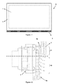
- FIG. 1 A front view of an audiovisual sound system (A) is illustrated in Figure 1 .
- the speaker grille (3) is located on the lower side of the frame (2) surrounding the screen (1) of the system (A).
- the speaker grille (3) may also be located on the other sides of the frame.
- FIG 2 a sectional view of an embodiment relating to a speaker grille (3p) already known in the art and location of it behind a screen frame (2).
- a certain part of each speaker (4) faces an area where the sound reaches out through the grille (3p) without being blocked by any barrier (active area (10)) and the remaining part faces another area where the sound is reflected back after striking a barrier (inactive area (11)).
- each speaker (4) is situated behind the screen frame (2) thus saving more place; however, the problem that the sound provided by the speaker (4) cannot be conveyed to the user in an effective way arises.
- FIG 3 a sectional view of the speaker grille (3) of this invention and its location behind a screen frame (2) belonging to the system (A) is provided.
- the speaker grille (3) here is also located in such a way that a certain part of it would be left behind the frame (2) or another barrier, and the other part would face an open area. Almost all or the most of the audio that is coming out of the speaker (4) behind the speaker grille (3) reach out through the openings (30) between the grille parts (31).
- an audio output channel (33) (explained below) which is provided on the part of the speaker grille (3), left behind the frame (2).
- the sound diverting surface (32) provided on the part of the speaker grille (3) that is behind the frame (2) in an inward-curving way to divert the audio output to the open side and with the audio output channel (33) provided through the grille part (31) next to that one, not only the frame (2) is prevented from blocking the audio output but also the speakers (4) and grilles (3) are located behind the frame (2) as much as possible.
- Sound diverting surface (32) can be designed in different geometrical forms such as flat, concave and convex surfaces.
- the sound diverting surface (32) may have a surface which is constructed with different combinations of at least two of the said flat, concave and convex surfaces.
Landscapes
- Physics & Mathematics (AREA)
- Engineering & Computer Science (AREA)
- Acoustics & Sound (AREA)
- Signal Processing (AREA)
- Stereophonic Arrangements (AREA)
- Details Of Audible-Bandwidth Transducers (AREA)
- Obtaining Desirable Characteristics In Audible-Bandwidth Transducers (AREA)
Abstract
Description
- This invention is related to the enhancements carried out on the structures of the grilles which are in front of the speakers located on one side of the screen frame used on all kinds of audiovisual sound systems.
- In order to lessen the space the audio-visual systems such as televisions occupy, a reduction in the size of the frames surrounding the screens is a subject-matter of work. The speaker grilles are the components which take up the widest space in the screen frames of those devices. Various grille designs are produced in order to protect the speakers from external influences and to provide the clearest sound possible. The published patent applications
EP1798967 ,JP2008005459 JP2007300281 US2007223747 , andUS7076078 can be listed as examples of those designs. As it can be inferred from those applications, the speakers and their grilles take up a significant space within the entire body of the televisions. - An embodiment already known in the art, aimed to reduce the space the speaker grilles occupy, is illustrated in the annexed figures (
Figure 2 ) as well. In this embodiment, a part of the speaker faces an area where the sound can pass through the grille directly without facing any barrier and the remaining part of the speaker faces another area where the sound, as it strikes a barrier, is reflected back. - In this embodiment intended to reduce the space the television occupies, a certain part of each speaker is situated behind the screen frame, thus saving more place; however, the problem that the sound cannot be conveyed to the user in an effective way comes forward. At the same time, the sound waves reflected back from the screen frame affects the performance of the speaker in a negative way. In other words, the part of the screen frame situated in front of the speaker blocks the sound passage and the sound reflected back by the barrier vibrates the speaker diaphragm in the reverse direction, causing a decrease in its performance.
- With this invention, enhancements are provided for speaker grilles in the screen frames of audiovisual sound systems. In particular, the sound provided by the speakers located behind the frames is ensured to pass out, facing the least number of barriers possible. To put it in other terms, the reflected part of the sound provided by the speakers is directed towards the outer side of the frame by means of the physical modification applied.
- In order to achieve this, the whole sound provided by the speaker behind the speaker grille is delivered out through the openings between the grille parts. This operation is ensured through an audio output channel provided on the part of the speaker grille that is behind the screen frame (it is explained in more detail in the description and in the claims).
- With the sound diverting surface provided on the part of the speaker grille that is behind the frame, in an inward-curving way to divert the audio output to the outer side (explained in more detail in the description and claims) and with the audio output channel provided through the grille part next to that one, not only the frame is prevented from blocking the audio output but also the speaker and the grille are located behind the frame as much as possible.
- The aim of this invention is to ensure the sound provided by the speakers behind the screen frames of the audiovisual sound systems to be less - affected by the barriers.
- Another aim of this invention is to ensure the speaker grilles to occupy less space on the screen frames.
- Another aim of this invention is to provide a speaker sound that is heard well, by means of modifications implemented on the design of the speaker grilles.
- Yet another aim of this invention is to lessen the space taken up by the screen frames.
- An exemplary embodiment of the audiovisual sound system according to this invention and the speaker grilles related to this are illustrated in the annexed figures; wherein,
-
Figure 1 is a front view of an exemplary audiovisual sound system, -
Figure 2 is a sectional side view of a speaker grille and screen frame of the prior art. -
Figure 3 is a sectional side view of the speaker grille and the screen frame according to this invention. - All the components illustrated in these figures are assigned reference numerals, which are listed below as;
- Audiovisual sound system (A)
- Screen (1)
- Frame (2)
- Speaker grille (3)
- Speaker grille (3p)
- Speaker (4)
- Active area (10)
- Inactive area (11)
- Grille opening (30)
- Grille part (31)
- Sound diverting surface (32)
- Audio output channel (33)
- A front view of an audiovisual sound system (A) is illustrated in
Figure 1 . As is shown in this embodiment, the speaker grille (3) is located on the lower side of the frame (2) surrounding the screen (1) of the system (A). With the structure provided by this invention, the speaker grille (3) may also be located on the other sides of the frame. - In
Figure 2 , a sectional view of an embodiment relating to a speaker grille (3p) already known in the art and location of it behind a screen frame (2). In this embodiment, a certain part of each speaker (4) faces an area where the sound reaches out through the grille (3p) without being blocked by any barrier (active area (10)) and the remaining part faces another area where the sound is reflected back after striking a barrier (inactive area (11)). - In this embodiment intended to reduce the space the system (A) occupies, a certain part of each speaker (4) is situated behind the screen frame (2) thus saving more place; however, the problem that the sound provided by the speaker (4) cannot be conveyed to the user in an effective way arises.
- In
Figure 3 , a sectional view of the speaker grille (3) of this invention and its location behind a screen frame (2) belonging to the system (A) is provided. The speaker grille (3) here is also located in such a way that a certain part of it would be left behind the frame (2) or another barrier, and the other part would face an open area. Almost all or the most of the audio that is coming out of the speaker (4) behind the speaker grille (3) reach out through the openings (30) between the grille parts (31). - This situation is achieved by means of an audio output channel (33) (explained below) which is provided on the part of the speaker grille (3), left behind the frame (2). With the sound diverting surface (32) provided on the part of the speaker grille (3) that is behind the frame (2), in an inward-curving way to divert the audio output to the open side and with the audio output channel (33) provided through the grille part (31) next to that one, not only the frame (2) is prevented from blocking the audio output but also the speakers (4) and grilles (3) are located behind the frame (2) as much as possible.
- Sound diverting surface (32) can be designed in different geometrical forms such as flat, concave and convex surfaces. Alternatively, the sound diverting surface (32) may have a surface which is constructed with different combinations of at least two of the said flat, concave and convex surfaces.
- With this invention, by means of one or more sound diverting surface(s) (32) used on the parts behind the frame (2) the sound reaches the outer side facing the least number of barriers possible. As it was mentioned earlier by this way, it is possible to use the speaker grilles (3) on the other sides of the frame (2) as well.
- With the grille (3) structure according to the invention, it is also possible to use speakers (4) of larger sizes behind the frame (2) and a better audio output may possibly be achieved.
Claims (5)
- An audiovisual sound system (A) comprising a screen (1) and a frame (2) surrounding it; a speaker grille (3) on at least one side of the frame (2); and at least one speaker (4) behind the grille (3), characterized in that;it comprises at least one sound diverting surface (32) on the part of the speaker grille (3) that is behind the frame (2) or a barrier, in an inward-curving way to divert the audio output to the open sideand an audio output channel (33) reaching out between an sound diverting surface (32) and a part of the grille (31) next to that one.
- A system (A) according to Claim 1, characterized in that the sound diverting surface (32) is in the form of a flat surface.
- A system (A) according to Claim 1, characterized in that the sound diverting surface (32) is in the form of a concave.
- A system (A) according to Claim 1, characterized in that the sound diverting surface (32) is in the form of a convex.
- A system (A) according to Claim 1, characterized in that the sound diverting surface (32) has a surface which is constructed with different combinations of at least two of the said flat, concave and convex surfaces.
Applications Claiming Priority (1)
| Application Number | Priority Date | Filing Date | Title |
|---|---|---|---|
| TR2008/07969A TR200807969A2 (en) | 2008-10-22 | 2008-10-22 | Speaker grille |
Publications (2)
| Publication Number | Publication Date |
|---|---|
| EP2180719A2 true EP2180719A2 (en) | 2010-04-28 |
| EP2180719A3 EP2180719A3 (en) | 2011-01-26 |
Family
ID=41478679
Family Applications (1)
| Application Number | Title | Priority Date | Filing Date |
|---|---|---|---|
| EP09173499A Withdrawn EP2180719A3 (en) | 2008-10-22 | 2009-10-20 | Speaker grille |
Country Status (2)
| Country | Link |
|---|---|
| EP (1) | EP2180719A3 (en) |
| TR (1) | TR200807969A2 (en) |
Cited By (1)
| Publication number | Priority date | Publication date | Assignee | Title |
|---|---|---|---|---|
| EP2811756A1 (en) * | 2013-06-04 | 2014-12-10 | Köck, Gerd | Loudspeaker |
Citations (6)
| Publication number | Priority date | Publication date | Assignee | Title |
|---|---|---|---|---|
| US3909530A (en) * | 1974-01-07 | 1975-09-30 | Federal Sign And Signal Corp | Loudspeaker with shallow re-entrant grille-like horn |
| US7076078B2 (en) | 2004-01-05 | 2006-07-11 | Action Electronics Co., Ltd. | LCD and speaker arrangement |
| EP1798967A2 (en) | 2005-12-14 | 2007-06-20 | ORION ELECTRIC CO., Ltd. | Display device |
| US20070223747A1 (en) | 2006-03-24 | 2007-09-27 | Victor Company Of Japan, Limited | Narrow speaker unit and image display apparatus having the narrow speaker |
| JP2007300281A (en) | 2006-04-28 | 2007-11-15 | Toshiba Corp | TV with built-in hard disk |
| JP2008005459A (en) | 2006-05-22 | 2008-01-10 | Sharp Corp | Display device |
Family Cites Families (2)
| Publication number | Priority date | Publication date | Assignee | Title |
|---|---|---|---|---|
| DE9313346U1 (en) * | 1993-09-04 | 1993-11-04 | Itw-Ateco Gmbh, 22844 Norderstedt | Cover for speakers |
| FR2748627B1 (en) * | 1996-05-07 | 1998-08-07 | Peugeot | SPEAKER GRID FORMING COVER AND MOTOR VEHICLE EQUIPPED WITH THIS GRID |
-
2008
- 2008-10-22 TR TR2008/07969A patent/TR200807969A2/en unknown
-
2009
- 2009-10-20 EP EP09173499A patent/EP2180719A3/en not_active Withdrawn
Patent Citations (6)
| Publication number | Priority date | Publication date | Assignee | Title |
|---|---|---|---|---|
| US3909530A (en) * | 1974-01-07 | 1975-09-30 | Federal Sign And Signal Corp | Loudspeaker with shallow re-entrant grille-like horn |
| US7076078B2 (en) | 2004-01-05 | 2006-07-11 | Action Electronics Co., Ltd. | LCD and speaker arrangement |
| EP1798967A2 (en) | 2005-12-14 | 2007-06-20 | ORION ELECTRIC CO., Ltd. | Display device |
| US20070223747A1 (en) | 2006-03-24 | 2007-09-27 | Victor Company Of Japan, Limited | Narrow speaker unit and image display apparatus having the narrow speaker |
| JP2007300281A (en) | 2006-04-28 | 2007-11-15 | Toshiba Corp | TV with built-in hard disk |
| JP2008005459A (en) | 2006-05-22 | 2008-01-10 | Sharp Corp | Display device |
Cited By (1)
| Publication number | Priority date | Publication date | Assignee | Title |
|---|---|---|---|---|
| EP2811756A1 (en) * | 2013-06-04 | 2014-12-10 | Köck, Gerd | Loudspeaker |
Also Published As
| Publication number | Publication date |
|---|---|
| TR200807969A2 (en) | 2010-05-21 |
| EP2180719A3 (en) | 2011-01-26 |
Similar Documents
| Publication | Publication Date | Title |
|---|---|---|
| EP2530951B1 (en) | Loudspeaker grille | |
| EP2822291B1 (en) | Speaker grille and assembly | |
| ES2793276T3 (en) | Speaker module for mobile device and mobile device with conduit radiation structure | |
| US10327066B2 (en) | Directional speaker and display apparatus having the same | |
| US8737665B2 (en) | Negative pressure earphone | |
| EP2761889B1 (en) | Dust protection of sound transducer | |
| US10178464B2 (en) | Earpiece | |
| US8208673B2 (en) | Miniaturized acoustic boom structure for reducing microphone wind noise and ESD susceptibility | |
| EP3772860B1 (en) | Mobile phone with an audio system having a rear secondary opening | |
| IL261150A (en) | Audio system having beam-shaping speakers and eyewear having such an audio system | |
| CN103299654A (en) | Display device | |
| US20140112512A1 (en) | Sound channel formed in a case to redirect sound with respect to a speaker of an electronic device positioned in the case | |
| EP1874081A3 (en) | Loudspeaker enclosure and loudspeaker system | |
| WO2008143629A3 (en) | Point source speaker systems | |
| US20200204894A1 (en) | Systems for reducing wind-induced noise and water infiltration in communication devices | |
| JPWO2011135678A1 (en) | Speaker device | |
| USD558814S1 (en) | Non-stretchable video projection screen | |
| USD554175S1 (en) | Non-stretchable video projection screen | |
| CN107786927A (en) | Speaker system | |
| WO2018150788A1 (en) | Acoustic lens and speaker system | |
| JP4390760B2 (en) | Speaker device and display device | |
| EP3367701B1 (en) | Hearing device with a microphone protection cover | |
| KR20060002538A (en) | 2-way speaker unit | |
| KR102091899B1 (en) | Block resistant microphone port design | |
| CN107155160B (en) | Speakers and Mobile Terminals |
Legal Events
| Date | Code | Title | Description |
|---|---|---|---|
| PUAI | Public reference made under article 153(3) epc to a published international application that has entered the european phase |
Free format text: ORIGINAL CODE: 0009012 |
|
| AK | Designated contracting states |
Kind code of ref document: A2 Designated state(s): AT BE BG CH CY CZ DE DK EE ES FI FR GB GR HR HU IE IS IT LI LT LU LV MC MK MT NL NO PL PT RO SE SI SK SM TR |
|
| PUAL | Search report despatched |
Free format text: ORIGINAL CODE: 0009013 |
|
| AK | Designated contracting states |
Kind code of ref document: A3 Designated state(s): AT BE BG CH CY CZ DE DK EE ES FI FR GB GR HR HU IE IS IT LI LT LU LV MC MK MT NL NO PL PT RO SE SI SK SM TR |
|
| RIC1 | Information provided on ipc code assigned before grant |
Ipc: H04R 1/02 20060101AFI20101222BHEP Ipc: H04R 1/34 20060101ALN20101222BHEP |
|
| 17P | Request for examination filed |
Effective date: 20110331 |
|
| 17Q | First examination report despatched |
Effective date: 20111201 |
|
| STAA | Information on the status of an ep patent application or granted ep patent |
Free format text: STATUS: THE APPLICATION HAS BEEN WITHDRAWN |
|
| 18W | Application withdrawn |
Effective date: 20171003 |