EP1798967A2 - Display device - Google Patents
Display device Download PDFInfo
- Publication number
- EP1798967A2 EP1798967A2 EP06256341A EP06256341A EP1798967A2 EP 1798967 A2 EP1798967 A2 EP 1798967A2 EP 06256341 A EP06256341 A EP 06256341A EP 06256341 A EP06256341 A EP 06256341A EP 1798967 A2 EP1798967 A2 EP 1798967A2
- Authority
- EP
- European Patent Office
- Prior art keywords
- chassis
- display device
- cabinet
- board
- internal components
- Prior art date
- Legal status (The legal status is an assumption and is not a legal conclusion. Google has not performed a legal analysis and makes no representation as to the accuracy of the status listed.)
- Withdrawn
Links
Images


Classifications
-
- H—ELECTRICITY
- H04—ELECTRIC COMMUNICATION TECHNIQUE
- H04N—PICTORIAL COMMUNICATION, e.g. TELEVISION
- H04N5/00—Details of television systems
- H04N5/64—Constructional details of receivers, e.g. cabinets or dust covers
Definitions
- the present invention relates to a display device, and more specifically, to a display device such as a liquid crystal display or a plasma display comprising a casing composed of a front cabinet and a back cabinet constituting the external appearance of the device and capable of being divided to front and rear portions, a display unit disposed in the interior of the casing and exposed to the exterior through an opening window formed on the front cabinet, and a chassis similarly assembled in the interior of the cabinet positioned on the rear side of the display unit.
- display devices utilizing liquid crystal or plasma for displaying video images such as television programs, DVD and video or for displaying the screen of personal computers
- Such display devices are respectively equipped with a display panel utilizing liquid crystal or plasma, display device supporting means for supporting the display device, a chassis for mounting the same, various circuit boards and a casing, but conventionally, these various components are assembled in a complex manner in order to manufacture the display device.
- the various circuit boards are mounted on various areas of the chassis, the casing and the like. Therefore, the assembly operation is complex.
- Patent document 1 discloses an art of simplifying the assembly operation by supporting and fixing the internal components via the casing, and an art of realizing a superior positional accuracy by providing ribs on the casing for supporting the components.
- the present invention aims at solving the problems mentioned above, by providing a display device capable of simplifying the assembly operation and maintenance operation. Furthermore, the present invention aims at providing a display device capable of simplifying the molds for forming the casing and reducing a sink mark occurring on the surface of the casing.
- the display device comprises a chassis and internal components disposed in an interior of a front cabinet constituting a front portion and a back cabinet constituting a rear portion of a casing capable of being divided in front and rear directions, characterized in that all the internal components are mounted on the chassis.
- the display device comprises a display device according to aspect 1, wherein the internal components are a display panel and a circuit board, and wherein an opening is formed on substantially the center area of the front cabinet, through which opening the display panel is exposed.
- the display device comprises a display device according to aspect 1, wherein the internal components are a display panel, a power supply board, an AV board, an MPEG board, a speaker, a recording and reproducing unit and an operation board, and wherein an opening is formed on substantially the center area of the front cabinet, through which opening the display panel is exposed, and an operation button is formed integrally on the surface of the front cabinet.
- the internal components are a display panel, a power supply board, an AV board, an MPEG board, a speaker, a recording and reproducing unit and an operation board, and wherein an opening is formed on substantially the center area of the front cabinet, through which opening the display panel is exposed, and an operation button is formed integrally on the surface of the front cabinet.
- the present invention it becomes possible to provide a display device capable of simplifying the assembly operation and maintenance operation by having all the internal components mounted on the chassis. Furthermore, it becomes possible to provide a display device capable of simplifying the molds for forming the casing and reducing the occurrence of the sink mark on the surface of the casing, since there is no need to form ribs for mounting internal components on the casing.
- the chassis acts as a basis to assemble all the internal components into a single unit to which the front cabinet and the back cabinet constituting the casing are attached, the components which were conventionally respectively attached to the casing and the chassis can all be assembled on a single chassis, so that the operation steps for manufacturing the display device can be improved. Furthermore, the maintenance operation such as repairing and testing operation can be performed by simply separating the front cabinet and the back cabinet.
- the forms of the front cabinet and the back cabinet can be simplified, and the molds for forming the same can also be desirably simplified, according to which the costs related to manufacturing the molds can be cut down.
- bosses and ribs formed on the front and back cabinets are reduced, the drawbacks related to the appearance of the front cabinet and the back cabinet such as the sink mark formed on the surface thereof can be reduced.
- the front cabinet and the back cabinet that are to be assembled to the front and rear sides of the internal unit are directly fixed to each other via screws, so that the number of screws can be reduced compared to the case where each cabinet is attached respectively to the internal unit, and the costs of the display device can be reduced by the reduction in the number of components.
- FIG. 1 is a perspective view showing the external appearance of a display device 1.
- the casing thereof is dividable into front and rear areas, and it is composed of a front cabinet 2 and a back cabinet 3.
- An opening window is formed on substantially the center portion of the front cabinet 2, through which is exposed a display panel 42.
- FIG. 4 is an exploded perspective view showing the state prior to attaching the front cabinet 2 and the back cabinet 3 to the internal unit 4.
- the front cabinet 2 and the back cabinet 3 are directly engaged via screws 7.
- FIGS. 5A and 5B are partially cross-sectional perspective view and cross-sectional side view of the display device 1.
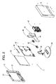
- FIG. 2 is an exploded perspective view illustrating the internal components of the display device 1.
- the internal components include the display panel 42 for displaying images, various circuit boards (such as a power supply board 43 for converting the input voltage supplied from an external power supply to a voltage used in the display device 1, an AV board 44 for processing audio signals and video signals, and an MPEG board 45 for encoding and decoding MPEG), a speaker 46 for outputting audio, a recording and reproducing unit 47 for recording and reproducing data on a DVD, the operation board 48 having switches being turned on and off in conjunction with an operation button 22 operated by a user by pressing the button, and a display device supporting means composed of a stand supporting unit 49 and a stand 50 for supporting the display device 1.
- These internal components are all mounted on a chassis 41.
- the front cabinet 2 has an opening window 21 formed substantially at the center thereof, and the operation button 22 disposed on the upper surface thereof.
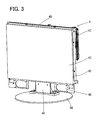
- FIG. 3 is a perspective view showing the internal unit 4 in which the internal components are formed into a unit with the chassis 41 acting as the basis, wherein all the internal components are mounted on the chassis 41.
- the display panel 42 is mounted on the front side of the chassis 41 (the side on which the front cabinet 2 will be positioned), and various circuit boards (power supply board 43, AV board 44 and MPEG board 45), the speaker 46 and the recording and reproducing unit 47 are mounted on the rear side of the chassis 41 (the side on which the back cabinet 3 will be positioned).
- a stand supporting unit 49 is attached to the bottom side of the chassis 41, and an operation board 48 is mounted on the upper surface of the chassis 41.
- the operation board 48 is mounted on the upper surface of the chassis 41, but the present invention is not restricted thereto, and the operation board 48 can be mounted on the chassis 41 corresponding to where the operation button 22 is disposed.
- the display device 1 is a display device 1 having a built-in recording and reproducing unit 47, but the present invention is not restricted thereto, and the display device can be a display device 1 without a built-in recording and reproducing unit 47.
- the display surface of the display panel 42 is positioned downward, and the chassis 41 is placed on the rear side of the display panel 42 (for example, if the display unit of the display panel 42 is disposed on the mounting surface such as a table, the rear side corresponds to the upper side of the display panel 42 placed on the mounting surface), and screws 7 are engaged from the side surfaces of the chassis 41 so as to assemble the display panel 42 with the chassis 41.
- the stand supporting unit 49 having the stand 50 attached thereto in advance is fixed via screws 7 to the bottom side of the chassis 41.
- the chassis 41 is raised so that the bottom side of the stand 50 is disposed as the mounting surface side, and then the operation board 48 having switches is fixed via screws 7 to the upper side of the chassis 41.
- the internal components of the display device 1 are formed as a unit with the chassis 41 acting as the basis (this unit is called the internal unit 4).
- front cabinet 2 and the back cabinet 3 are assembled and fixed via screws 7 to the front side of the internal unit 4 (on the side of the chassis 41 where the display panel 42 is mounted) and the rear side thereof (the side of the chassis 41 on which the various circuit boards, the speaker 46 and the recording and reproducing unit 47 are mounted).
- the order for mounting the internal components on the chassis 41 can be varied from that described above (that is, the various circuit boards, the stand supporting unit 49 and the like can be mounted on the chassis 41 before mounting the display panel 42, as long as the front cabinet 2 and the back cabinet 3 constituting the casing are mounted at the final step).
- the front cabinet 2 and the back cabinet 3 has bosses and holes formed thereto for directly engaging the front cabinet 2 and the back cabinet 3 via screws 7. That is, by engaging the front cabinet 2 and the back cabinet 3 directly, it becomes possible to reduce the number of screws 7 used for engagement compared to the case where the front cabinet 2 and the back cabinet 3 are respectively engaged and fixed to the internal unit 4.
- through holes to the chassis 41 of the internal unit 4 capable of having bosses formed on the front cabinet 2 pass therethrough, so that the bosses on the front cabinet 2 can be protruded through the through holes to the rear side of the internal unit 4 and assembled with the holes on the back cabinet 3, and have screws 7 engaged thereto from the rear side of the back cabinet 3.
- the present invention enables to provide a display device capable of simplifying the assembling operation and maintenance operation by having all the internal components mounted on the chassis. Further, the present invention provides a display device where the casing does not have any ribs for mounting the internal components, so that the casing can be formed using simplified molds, and the occurrence of a sink mark on the surface of the casing can be reduced. Moreover, the present invention provides a display device capable of reducing the number of screws by designing the front cabinet and the back cabinet to be fixed to each other directly via screws.
Abstract
Description
- The present invention relates to a display device, and more specifically, to a display device such as a liquid crystal display or a plasma display comprising a casing composed of a front cabinet and a back cabinet constituting the external appearance of the device and capable of being divided to front and rear portions, a display unit disposed in the interior of the casing and exposed to the exterior through an opening window formed on the front cabinet, and a chassis similarly assembled in the interior of the cabinet positioned on the rear side of the display unit.
- Recently, display devices utilizing liquid crystal or plasma for displaying video images such as television programs, DVD and video or for displaying the screen of personal computers have been developed and distributed. Such display devices are respectively equipped with a display panel utilizing liquid crystal or plasma, display device supporting means for supporting the display device, a chassis for mounting the same, various circuit boards and a casing, but conventionally, these various components are assembled in a complex manner in order to manufacture the display device. For example, the various circuit boards are mounted on various areas of the chassis, the casing and the like. Therefore, the assembly operation is complex.
-
Japanese Patent Application Laid-Open Publication No. 2003-167235 - By utilizing the art disclosed in patent document 1, the assembly operation can be simplified, but when it is necessary to perform maintenance operation such as repairing and testing, the maintenance operation becomes complex since the internal components are attached to the casing. Another drawback of the prior art is that the design of the molds for forming the casing having ribs for attaching the internal components to the casing becomes complex, and yet another drawback is that a number of sink marks occur on the surface of the casing.
- The present invention aims at solving the problems mentioned above, by providing a display device capable of simplifying the assembly operation and maintenance operation. Furthermore, the present invention aims at providing a display device capable of simplifying the molds for forming the casing and reducing a sink mark occurring on the surface of the casing.
- The display device according to a first aspect comprises a chassis and internal components disposed in an interior of a front cabinet constituting a front portion and a back cabinet constituting a rear portion of a casing capable of being divided in front and rear directions, characterized in that all the internal components are mounted on the chassis.
- The display device according to a second aspect comprises a display device according to aspect 1, wherein the internal components are a display panel and a circuit board, and wherein an opening is formed on substantially the center area of the front cabinet, through which opening the display panel is exposed.
- The display device according to a third aspect comprises a display device according to aspect 1, wherein the internal components are a display panel, a power supply board, an AV board, an MPEG board, a speaker, a recording and reproducing unit and an operation board, and wherein an opening is formed on substantially the center area of the front cabinet, through which opening the display panel is exposed, and an operation button is formed integrally on the surface of the front cabinet.
- The display device according to a fourth aspect comprises a display device according to any one of aspects 1 through 3, wherein the front cabinet and the back cabinet are attached directly.
- According to the present invention, it becomes possible to provide a display device capable of simplifying the assembly operation and maintenance operation by having all the internal components mounted on the chassis. Furthermore, it becomes possible to provide a display device capable of simplifying the molds for forming the casing and reducing the occurrence of the sink mark on the surface of the casing, since there is no need to form ribs for mounting internal components on the casing.
- According to the present invention, since the chassis acts as a basis to assemble all the internal components into a single unit to which the front cabinet and the back cabinet constituting the casing are attached, the components which were conventionally respectively attached to the casing and the chassis can all be assembled on a single chassis, so that the operation steps for manufacturing the display device can be improved. Furthermore, the maintenance operation such as repairing and testing operation can be performed by simply separating the front cabinet and the back cabinet.
- Furthermore, according to the present invention in which the internal components are assembled into a unit, it becomes unnecessary to form mounting bosses and positioning ribs for mounting the internal components on the front cabinet and the back cabinet, so the forms of the front cabinet and the back cabinet can be simplified, and the molds for forming the same can also be desirably simplified, according to which the costs related to manufacturing the molds can be cut down. Moreover, since bosses and ribs formed on the front and back cabinets are reduced, the drawbacks related to the appearance of the front cabinet and the back cabinet such as the sink mark formed on the surface thereof can be reduced.
- Further according to the present invention, the front cabinet and the back cabinet that are to be assembled to the front and rear sides of the internal unit (a unit formed by mounting the internal components to the chassis acting as the basis) are directly fixed to each other via screws, so that the number of screws can be reduced compared to the case where each cabinet is attached respectively to the internal unit, and the costs of the display device can be reduced by the reduction in the number of components.
-
- FIG. 1 is a perspective view showing the external appearance of a display device according to a preferred embodiment of the present invention;
- FIG. 2 is an exploded perspective view showing the internal components of the display device according to the preferred embodiment of the present invention;
- FIG. 3 is a perspective view showing the internal unit in which the internal components are formed as a unit with the chassis acting as the basis according to the present embodiment;
- FIG. 4 is an exploded perspective view showing the state prior to attaching the front cabinet and back cabinet to the internal unit according to the embodiment of the present invention; and
- FIG. 5 is a partially cross-sectional perspective view and a cross-sectional side view of the display device according to the embodiment of the present invention.
- Now, the preferred embodiment of the present invention will be described with reference to the drawings. The following embodiment is a mere example of the present invention, and it will not restrict the scope of the present invention.
- FIG. 1 is a perspective view showing the external appearance of a display device 1. The casing thereof is dividable into front and rear areas, and it is composed of a
front cabinet 2 and aback cabinet 3. An opening window is formed on substantially the center portion of thefront cabinet 2, through which is exposed adisplay panel 42. FIG. 4 is an exploded perspective view showing the state prior to attaching thefront cabinet 2 and theback cabinet 3 to theinternal unit 4. Thefront cabinet 2 and theback cabinet 3 are directly engaged viascrews 7. FIGS. 5A and 5B are partially cross-sectional perspective view and cross-sectional side view of the display device 1. - FIG. 2 is an exploded perspective view illustrating the internal components of the display device 1. Here, the internal components include the
display panel 42 for displaying images, various circuit boards (such as apower supply board 43 for converting the input voltage supplied from an external power supply to a voltage used in the display device 1, anAV board 44 for processing audio signals and video signals, and anMPEG board 45 for encoding and decoding MPEG), aspeaker 46 for outputting audio, a recording and reproducingunit 47 for recording and reproducing data on a DVD, theoperation board 48 having switches being turned on and off in conjunction with anoperation button 22 operated by a user by pressing the button, and a display device supporting means composed of astand supporting unit 49 and astand 50 for supporting the display device 1. These internal components are all mounted on achassis 41. Thefront cabinet 2 has anopening window 21 formed substantially at the center thereof, and theoperation button 22 disposed on the upper surface thereof. - FIG. 3 is a perspective view showing the
internal unit 4 in which the internal components are formed into a unit with thechassis 41 acting as the basis, wherein all the internal components are mounted on thechassis 41. Actually, thedisplay panel 42 is mounted on the front side of the chassis 41 (the side on which thefront cabinet 2 will be positioned), and various circuit boards (power supply board 43,AV board 44 and MPEG board 45), thespeaker 46 and the recording and reproducingunit 47 are mounted on the rear side of the chassis 41 (the side on which theback cabinet 3 will be positioned). Astand supporting unit 49 is attached to the bottom side of thechassis 41, and anoperation board 48 is mounted on the upper surface of thechassis 41. According to the present embodiment, theoperation board 48 is mounted on the upper surface of thechassis 41, but the present invention is not restricted thereto, and theoperation board 48 can be mounted on thechassis 41 corresponding to where theoperation button 22 is disposed. - Now, an embodiment of the steps for mounting the internal components onto the
chassis 41 will be described. The display device 1 according to the present embodiment is a display device 1 having a built-in recording and reproducingunit 47, but the present invention is not restricted thereto, and the display device can be a display device 1 without a built-in recording and reproducingunit 47. - At first, the display surface of the
display panel 42 is positioned downward, and thechassis 41 is placed on the rear side of the display panel 42 (for example, if the display unit of thedisplay panel 42 is disposed on the mounting surface such as a table, the rear side corresponds to the upper side of thedisplay panel 42 placed on the mounting surface), andscrews 7 are engaged from the side surfaces of thechassis 41 so as to assemble thedisplay panel 42 with thechassis 41. - Next, various circuit boards (
power supply board 43,AV board 44 and MPEG board 45), thespeaker 46 and the recording and reproducingunit 47 are fixed viascrews 7 on the rear side of thechassis 41. - Thereafter, the
stand supporting unit 49 having thestand 50 attached thereto in advance is fixed viascrews 7 to the bottom side of thechassis 41. - Next, the
chassis 41 is raised so that the bottom side of thestand 50 is disposed as the mounting surface side, and then theoperation board 48 having switches is fixed viascrews 7 to the upper side of thechassis 41. Thus, the internal components of the display device 1 are formed as a unit with thechassis 41 acting as the basis (this unit is called the internal unit 4). - Finally, the
front cabinet 2 and theback cabinet 3 are assembled and fixed viascrews 7 to the front side of the internal unit 4 (on the side of thechassis 41 where thedisplay panel 42 is mounted) and the rear side thereof (the side of thechassis 41 on which the various circuit boards, thespeaker 46 and the recording and reproducingunit 47 are mounted). - Except for the final step of sandwiching the
internal unit 4 with thefront cabinet 2 and theback cabinet 3, the order for mounting the internal components on thechassis 41 can be varied from that described above (that is, the various circuit boards, thestand supporting unit 49 and the like can be mounted on thechassis 41 before mounting thedisplay panel 42, as long as thefront cabinet 2 and theback cabinet 3 constituting the casing are mounted at the final step). - Furthermore, upon assembling the
internal unit 4, thefront cabinet 2 and theback cabinet 3, it is preferable that thefront cabinet 2 and theback cabinet 3 has bosses and holes formed thereto for directly engaging thefront cabinet 2 and theback cabinet 3 viascrews 7. That is, by engaging thefront cabinet 2 and theback cabinet 3 directly, it becomes possible to reduce the number ofscrews 7 used for engagement compared to the case where thefront cabinet 2 and theback cabinet 3 are respectively engaged and fixed to theinternal unit 4. Further, it is most preferable to form through holes to thechassis 41 of theinternal unit 4 capable of having bosses formed on thefront cabinet 2 pass therethrough, so that the bosses on thefront cabinet 2 can be protruded through the through holes to the rear side of theinternal unit 4 and assembled with the holes on theback cabinet 3, and havescrews 7 engaged thereto from the rear side of theback cabinet 3. - As described, the present invention enables to provide a display device capable of simplifying the assembling operation and maintenance operation by having all the internal components mounted on the chassis. Further, the present invention provides a display device where the casing does not have any ribs for mounting the internal components, so that the casing can be formed using simplified molds, and the occurrence of a sink mark on the surface of the casing can be reduced. Moreover, the present invention provides a display device capable of reducing the number of screws by designing the front cabinet and the back cabinet to be fixed to each other directly via screws.
Claims (4)
- A display device comprising a chassis and internal components disposed in an interior of a front cabinet constituting a front portion and a back cabinet constituting a rear portion of a casing capable of being divided in front and rear directions, characterized in that all the internal components are mounted on the chassis.
- The display device according to claim 1, wherein the internal components are a display panel and a circuit board, and wherein an opening is formed on substantially the center area of the front cabinet, through which opening the display panel is exposed.
- The display device according to claim 1, wherein the internal components are a display panel, a power supply board, an AV board, an MPEG board, a speaker, a recording and reproducing unit and an operation board, and wherein an opening is formed on substantially the center area of the front cabinet, through which opening the display panel is exposed, and an operation button is formed integrally on the surface of the front cabinet.
- The display device according to any one of claims 1 through 3, wherein the front cabinet and the back cabinet are attached directly.
Applications Claiming Priority (1)
| Application Number | Priority Date | Filing Date | Title |
|---|---|---|---|
| JP2005360339A JP2007163861A (en) | 2005-12-14 | 2005-12-14 | Display apparatus |
Publications (2)
| Publication Number | Publication Date |
|---|---|
| EP1798967A2 true EP1798967A2 (en) | 2007-06-20 |
| EP1798967A3 EP1798967A3 (en) | 2008-03-05 |
Family
ID=37903466
Family Applications (1)
| Application Number | Title | Priority Date | Filing Date |
|---|---|---|---|
| EP06256341A Withdrawn EP1798967A3 (en) | 2005-12-14 | 2006-12-13 | Display device |
Country Status (3)
| Country | Link |
|---|---|
| US (1) | US20070133158A1 (en) |
| EP (1) | EP1798967A3 (en) |
| JP (1) | JP2007163861A (en) |
Cited By (4)
| Publication number | Priority date | Publication date | Assignee | Title |
|---|---|---|---|---|
| EP2076107A3 (en) * | 2007-12-28 | 2009-10-07 | Orion Electric Co., Ltd | Display device |
| EP2180719A2 (en) | 2008-10-22 | 2010-04-28 | Vestel Elektronik Sanayi ve Ticaret A.S. | Speaker grille |
| EP2350942A1 (en) * | 2008-09-19 | 2011-08-03 | Logomotion, s.r.o. | The electronic payment application system and payment authorization method |
| EP2565743A3 (en) * | 2011-08-30 | 2014-11-26 | Funai Electric Co., Ltd. | Display device and television device |
Families Citing this family (10)
| Publication number | Priority date | Publication date | Assignee | Title |
|---|---|---|---|---|
| CN1582105B (en) * | 2003-08-04 | 2010-05-26 | 三星电子株式会社 | Display device and its method |
| US7969719B2 (en) | 2006-01-04 | 2011-06-28 | Westinghouse Digital, Llc | Back panel for video display device |
| US20080186664A1 (en) * | 2006-10-04 | 2008-08-07 | Westinghouse Digital Electronics, Llc | Back Panel for Video Display Device Including Replaceable Slide-Out Electronic Components |
| TWI375505B (en) * | 2008-10-24 | 2012-10-21 | Wistron Corp | Frame structure and display apparatus using the same |
| CN101729954B (en) * | 2008-10-28 | 2013-08-07 | 深圳富泰宏精密工业有限公司 | Audio cavity structure |
| CN102262418A (en) * | 2010-05-27 | 2011-11-30 | 鸿富锦精密工业(深圳)有限公司 | Desktop computer |
| TWM395870U (en) * | 2010-08-10 | 2011-01-01 | Jazz Hipster Corp | Hanging structure for electronic whiteboard sound device |
| WO2012042797A1 (en) | 2010-09-28 | 2012-04-05 | パナソニック株式会社 | Display device |
| EP2693263A1 (en) | 2012-07-31 | 2014-02-05 | Orion Electric Company, LTD. | Display device |
| KR102209145B1 (en) * | 2014-08-18 | 2021-01-29 | 삼성디스플레이 주식회사 | Display device |
Citations (4)
| Publication number | Priority date | Publication date | Assignee | Title |
|---|---|---|---|---|
| US20020080113A1 (en) * | 2000-12-27 | 2002-06-27 | Ju-Hwan Kim | OSD controller assembly and assembling process in a displaying apparatus |
| US20040036819A1 (en) * | 2002-08-26 | 2004-02-26 | Ho-Chul Ryu | Case for covering electronic parts and display apparatus including the same |
| US20050078446A1 (en) * | 2003-10-09 | 2005-04-14 | Sung-Won Bae | Plasma display apparatus |
| EP1585324A1 (en) * | 2004-03-31 | 2005-10-12 | ORION ELECTRIC CO., Ltd. | Liquid crystal television device comprising a recording/reproducing device such as a dvd recorder/player or the like |
Family Cites Families (2)
| Publication number | Priority date | Publication date | Assignee | Title |
|---|---|---|---|---|
| TW445386B (en) * | 1998-03-16 | 2001-07-11 | Hitachi Ltd | Thin-type display |
| US6229584B1 (en) * | 1999-11-15 | 2001-05-08 | Compal Electronics, Inc. | Liquid crystal display monitor having a monitor stand with a replaceable housing part |
-
2005
- 2005-12-14 JP JP2005360339A patent/JP2007163861A/en active Pending
-
2006
- 2006-12-11 US US11/636,662 patent/US20070133158A1/en not_active Abandoned
- 2006-12-13 EP EP06256341A patent/EP1798967A3/en not_active Withdrawn
Patent Citations (4)
| Publication number | Priority date | Publication date | Assignee | Title |
|---|---|---|---|---|
| US20020080113A1 (en) * | 2000-12-27 | 2002-06-27 | Ju-Hwan Kim | OSD controller assembly and assembling process in a displaying apparatus |
| US20040036819A1 (en) * | 2002-08-26 | 2004-02-26 | Ho-Chul Ryu | Case for covering electronic parts and display apparatus including the same |
| US20050078446A1 (en) * | 2003-10-09 | 2005-04-14 | Sung-Won Bae | Plasma display apparatus |
| EP1585324A1 (en) * | 2004-03-31 | 2005-10-12 | ORION ELECTRIC CO., Ltd. | Liquid crystal television device comprising a recording/reproducing device such as a dvd recorder/player or the like |
Cited By (5)
| Publication number | Priority date | Publication date | Assignee | Title |
|---|---|---|---|---|
| EP2076107A3 (en) * | 2007-12-28 | 2009-10-07 | Orion Electric Co., Ltd | Display device |
| EP2350942A1 (en) * | 2008-09-19 | 2011-08-03 | Logomotion, s.r.o. | The electronic payment application system and payment authorization method |
| AU2009294210B2 (en) * | 2008-09-19 | 2015-11-19 | Smk-Logomotion Corporation | The electronic payment application system and payment authorization method |
| EP2180719A2 (en) | 2008-10-22 | 2010-04-28 | Vestel Elektronik Sanayi ve Ticaret A.S. | Speaker grille |
| EP2565743A3 (en) * | 2011-08-30 | 2014-11-26 | Funai Electric Co., Ltd. | Display device and television device |
Also Published As
| Publication number | Publication date |
|---|---|
| US20070133158A1 (en) | 2007-06-14 |
| EP1798967A3 (en) | 2008-03-05 |
| JP2007163861A (en) | 2007-06-28 |
Similar Documents
| Publication | Publication Date | Title |
|---|---|---|
| EP1798967A2 (en) | Display device | |
| US9263842B2 (en) | Method for assembling an electronic device | |
| EP1879363B1 (en) | Mobile terminal | |
| KR100383428B1 (en) | Structure for mounting a liquid crystal module, and portable data terminal or information processing equipment using this structure | |
| JP2017084413A (en) | Electronic device housing and assembling method | |
| US20060209228A1 (en) | Liquid crystal display device with LCD cover | |
| JP4199292B1 (en) | Display device | |
| US20060067557A1 (en) | Electronic apparatus | |
| JP2001033761A (en) | Liquid module mounting structure | |
| JP5017473B1 (en) | Television receiver and electronic device | |
| JP2008141139A (en) | Electronic apparatus, flexible substrate, and substrate-fixing member | |
| KR101164822B1 (en) | Information processing apparatus and manufacturing method for the same | |
| US20060002063A1 (en) | Liquid crystal display device | |
| US20070206123A1 (en) | Liquid crystal television | |
| JP4937707B2 (en) | Electronic device including a metal housing and a decorative envelope | |
| JP2009159084A (en) | Display device | |
| JP4122460B2 (en) | Disc device integrated liquid crystal display device | |
| JP2007114566A (en) | Video display device with operation button, and method for assembling same | |
| JP2007235413A (en) | Liquid crystal television receiver | |
| JP2005191029A (en) | Operation button and electrical apparatus having the same | |
| JP2010233138A (en) | Display | |
| US20120236215A1 (en) | Tv receiver and electronic apparatus | |
| JP4116375B2 (en) | Thin display device | |
| JP3121977U (en) | Electronic equipment with an operation unit in the cabinet | |
| JPH0846372A (en) | Holder for printed board |
Legal Events
| Date | Code | Title | Description |
|---|---|---|---|
| PUAI | Public reference made under article 153(3) epc to a published international application that has entered the european phase |
Free format text: ORIGINAL CODE: 0009012 |
|
| AK | Designated contracting states |
Kind code of ref document: A2 Designated state(s): AT BE BG CH CY CZ DE DK EE ES FI FR GB GR HU IE IS IT LI LT LU LV MC NL PL PT RO SE SI SK TR |
|
| AX | Request for extension of the european patent |
Extension state: AL BA HR MK YU |
|
| PUAL | Search report despatched |
Free format text: ORIGINAL CODE: 0009013 |
|
| AK | Designated contracting states |
Kind code of ref document: A3 Designated state(s): AT BE BG CH CY CZ DE DK EE ES FI FR GB GR HU IE IS IT LI LT LU LV MC NL PL PT RO SE SI SK TR |
|
| AX | Request for extension of the european patent |
Extension state: AL BA HR MK YU |
|
| AKX | Designation fees paid | ||
| REG | Reference to a national code |
Ref country code: DE Ref legal event code: 8566 |
|
| STAA | Information on the status of an ep patent application or granted ep patent |
Free format text: STATUS: THE APPLICATION IS DEEMED TO BE WITHDRAWN |
|
| 18D | Application deemed to be withdrawn |
Effective date: 20080906 |