EP2180525A2 - Photovoltaikfliese - Google Patents
Photovoltaikfliese Download PDFInfo
- Publication number
- EP2180525A2 EP2180525A2 EP09153771A EP09153771A EP2180525A2 EP 2180525 A2 EP2180525 A2 EP 2180525A2 EP 09153771 A EP09153771 A EP 09153771A EP 09153771 A EP09153771 A EP 09153771A EP 2180525 A2 EP2180525 A2 EP 2180525A2
- Authority
- EP
- European Patent Office
- Prior art keywords
- photovoltaic
- tile
- carrier
- photovoltaic tile
- electrical
- Prior art date
- Legal status (The legal status is an assumption and is not a legal conclusion. Google has not performed a legal analysis and makes no representation as to the accuracy of the status listed.)
- Withdrawn
Links
- 239000010454 slate Substances 0.000 claims abstract description 4
- 239000004020 conductor Substances 0.000 claims description 16
- 230000005611 electricity Effects 0.000 claims description 4
- 239000000463 material Substances 0.000 claims description 3
- 238000000034 method Methods 0.000 claims description 3
- 229920003023 plastic Polymers 0.000 claims description 3
- 238000000465 moulding Methods 0.000 claims description 2
- 239000004033 plastic Substances 0.000 claims description 2
- 230000003278 mimic effect Effects 0.000 abstract 1
- 238000007789 sealing Methods 0.000 description 6
- 230000000694 effects Effects 0.000 description 5
- 239000000758 substrate Substances 0.000 description 5
- 239000011159 matrix material Substances 0.000 description 4
- 241000237983 Trochidae Species 0.000 description 3
- 230000008878 coupling Effects 0.000 description 3
- 238000010168 coupling process Methods 0.000 description 3
- 238000005859 coupling reaction Methods 0.000 description 3
- 238000010586 diagram Methods 0.000 description 3
- 230000002093 peripheral effect Effects 0.000 description 3
- 230000015572 biosynthetic process Effects 0.000 description 2
- 230000000295 complement effect Effects 0.000 description 2
- 238000010276 construction Methods 0.000 description 2
- 230000001419 dependent effect Effects 0.000 description 2
- 238000012986 modification Methods 0.000 description 2
- 230000004048 modification Effects 0.000 description 2
- 238000003860 storage Methods 0.000 description 2
- 239000000853 adhesive Substances 0.000 description 1
- 230000001070 adhesive effect Effects 0.000 description 1
- 230000002411 adverse Effects 0.000 description 1
- 239000011324 bead Substances 0.000 description 1
- 230000005540 biological transmission Effects 0.000 description 1
- 238000004040 coloring Methods 0.000 description 1
- 238000005520 cutting process Methods 0.000 description 1
- 238000013461 design Methods 0.000 description 1
- 210000003608 fece Anatomy 0.000 description 1
- 238000005286 illumination Methods 0.000 description 1
- 239000011810 insulating material Substances 0.000 description 1
- 239000000203 mixture Substances 0.000 description 1
- 238000012827 research and development Methods 0.000 description 1
- 239000000565 sealant Substances 0.000 description 1
- 239000012812 sealant material Substances 0.000 description 1
- 238000005476 soldering Methods 0.000 description 1
- 239000013589 supplement Substances 0.000 description 1
- 238000012546 transfer Methods 0.000 description 1
- 239000012780 transparent material Substances 0.000 description 1
- XLYOFNOQVPJJNP-UHFFFAOYSA-N water Substances O XLYOFNOQVPJJNP-UHFFFAOYSA-N 0.000 description 1
- 238000003466 welding Methods 0.000 description 1
Images


Classifications
-
- H—ELECTRICITY
- H02—GENERATION; CONVERSION OR DISTRIBUTION OF ELECTRIC POWER
- H02S—GENERATION OF ELECTRIC POWER BY CONVERSION OF INFRARED RADIATION, VISIBLE LIGHT OR ULTRAVIOLET LIGHT, e.g. USING PHOTOVOLTAIC [PV] MODULES
- H02S20/00—Supporting structures for PV modules
- H02S20/20—Supporting structures directly fixed to an immovable object
- H02S20/22—Supporting structures directly fixed to an immovable object specially adapted for buildings
- H02S20/23—Supporting structures directly fixed to an immovable object specially adapted for buildings specially adapted for roof structures
- H02S20/25—Roof tile elements
-
- H—ELECTRICITY
- H02—GENERATION; CONVERSION OR DISTRIBUTION OF ELECTRIC POWER
- H02S—GENERATION OF ELECTRIC POWER BY CONVERSION OF INFRARED RADIATION, VISIBLE LIGHT OR ULTRAVIOLET LIGHT, e.g. USING PHOTOVOLTAIC [PV] MODULES
- H02S20/00—Supporting structures for PV modules
- H02S20/20—Supporting structures directly fixed to an immovable object
- H02S20/22—Supporting structures directly fixed to an immovable object specially adapted for buildings
- H02S20/26—Building materials integrated with PV modules, e.g. façade elements
-
- E—FIXED CONSTRUCTIONS
- E04—BUILDING
- E04D—ROOF COVERINGS; SKY-LIGHTS; GUTTERS; ROOF-WORKING TOOLS
- E04D1/00—Roof covering by making use of tiles, slates, shingles, or other small roofing elements
- E04D1/30—Special roof-covering elements, e.g. ridge tiles, gutter tiles, gable tiles, ventilation tiles
-
- E—FIXED CONSTRUCTIONS
- E04—BUILDING
- E04D—ROOF COVERINGS; SKY-LIGHTS; GUTTERS; ROOF-WORKING TOOLS
- E04D13/00—Special arrangements or devices in connection with roof coverings; Protection against birds; Roof drainage; Sky-lights
-
- Y—GENERAL TAGGING OF NEW TECHNOLOGICAL DEVELOPMENTS; GENERAL TAGGING OF CROSS-SECTIONAL TECHNOLOGIES SPANNING OVER SEVERAL SECTIONS OF THE IPC; TECHNICAL SUBJECTS COVERED BY FORMER USPC CROSS-REFERENCE ART COLLECTIONS [XRACs] AND DIGESTS
- Y02—TECHNOLOGIES OR APPLICATIONS FOR MITIGATION OR ADAPTATION AGAINST CLIMATE CHANGE
- Y02B—CLIMATE CHANGE MITIGATION TECHNOLOGIES RELATED TO BUILDINGS, e.g. HOUSING, HOUSE APPLIANCES OR RELATED END-USER APPLICATIONS
- Y02B10/00—Integration of renewable energy sources in buildings
- Y02B10/10—Photovoltaic [PV]
-
- Y—GENERAL TAGGING OF NEW TECHNOLOGICAL DEVELOPMENTS; GENERAL TAGGING OF CROSS-SECTIONAL TECHNOLOGIES SPANNING OVER SEVERAL SECTIONS OF THE IPC; TECHNICAL SUBJECTS COVERED BY FORMER USPC CROSS-REFERENCE ART COLLECTIONS [XRACs] AND DIGESTS
- Y02—TECHNOLOGIES OR APPLICATIONS FOR MITIGATION OR ADAPTATION AGAINST CLIMATE CHANGE
- Y02E—REDUCTION OF GREENHOUSE GAS [GHG] EMISSIONS, RELATED TO ENERGY GENERATION, TRANSMISSION OR DISTRIBUTION
- Y02E10/00—Energy generation through renewable energy sources
- Y02E10/50—Photovoltaic [PV] energy
Definitions
- the present invention relates to a photovoltaic tile particularly, though not exclusively, for use on the roof of a building for converting solar energy to electrical energy.
- the assembly comprises a base tile through which one or more mechanical fasteners are driven for fastening to an underlying roof structure, and one or more photovoltaic cover tiles that are attached to, and overlie, the base tile.
- Each of the cover tiles is provided with one or more photovoltaic cells for converting solar energy into electrical energy.
- the cover tiles are electrically and mechanically coupled to a corresponding base tile by connection posts.
- the posts are pushed through holes formed in the base tile.
- a first end of each post extends above the base tile and is received in a through hole electric terminal in the cover tile to provide electrical and mechanical coupling of the cover tile to the base tile.
- a second opposite end of each post extends into a recess on the base tile and is received in a slot in an electrical connection tube that is subsequently seated in the recess in the base tile. Electrical and mechanical connection of the second end of the post requires a combined linear and rotational motion of the connection tube.
- the present invention is a result of further research and development in relation to the cover tile in the above-described photovoltaic tile assembly.
- One aspect of the present invention provides a photovoltaic tile comprising:
- the carrier tile may be made from a plastics material. Further, the carrier tile may be formed by a molding process.
- the photovoltaic tile when viewed from a side provided with the photovoltaic cells has a slate-like appearance.
- the carrier tile is of a slate-like colour.
- the photovoltaic cells may also be of a slate-like colour, or alternatively may be formed to be substantially transparent wherein the underlying carrier tile is visible through the photovoltaic cells.
- the cover plate may overlie the carrier tile. Further, the cover plate may be of substantially the same footprint as the carrier tiles so that the edges of the carrier tile and cover plate are substantially co-terminus. This provides the photovoltaic tile with an upper surface that is substantially flat. In this embodiment the photovoltaic cells have a combined thickness substantially equal to or less than a depth of the recess.
- the cover plate may be seated in the recess.
- the photovoltaic cell and the cover plate may be formed to have a combined thickness substantially equal to a depth of the recess. This results in an upper surface of the photovoltaic tile (that is the surface which is provided with the cover plate) being substantially flat.
- At least one edge of the photovoltaic tile may be provided with a curved or rounded profile.
- One or more electrical terminals are provided on the photovoltaic tile through which electricity generated by the photovoltaic cell can flow to a remote electrical device; such as for example a storage battery, a water heater, an inverter or an electric appliance.
- a remote electrical device such as for example a storage battery, a water heater, an inverter or an electric appliance.
- a hole may be provided in the photovoltaic tile to receive a fastener for holding or fastening the photovoltaic tile assembly in a desired location or position or to a support.
- each electrical terminal may be located adjacent the hole. Indeed each terminal may circumscribe a respective hole.
- each electrical terminal is a through hole terminal and may comprise a ring made of electrically conducting material.
- Each electrical conductor is provided to establish electrical connection between each electrical terminal and the photovoltaic cell.
- Each electrical conductor may be in the form of a bus bar.
- Each bus bar can be coupled to a corresponding electrical terminal.
- the electrical terminals and bus bars may be molded into the carrier tile.
- the electrical terminal and/or the electrical conducted may be sandwiched between the carrier tile and the cover plate.
- the electrical terminal and/or the electrical conductor may be embedded in the carrier tile.
- a further aspect of the invention comprises a photovoltaic tile comprising:
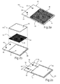
- an embodiment of the photovoltaic tile 10 in accordance with the present invention comprises a carrier tile 12 and a photovoltaic cell 14.
- the carrier tile 12 has a first side 18 on which is provided a recess 20.
- the photovoltaic cell 14 is dimensioned relative to the recess 20 so that the cell 14 is seated in the recess 20.
- a cover plate 16 overlies the photovoltaic cell 14 and can be sealed to the carrier tile 12.
- the cover plate 16 has substantially the same footprint as the carrier tile 12, and is juxtaposed so that the edges of the plate 16 and the tile 12 are co-terminus.
- a front or exposed face 22 of the photovoltaic tile 10 is provided with a flat surface 24.
- the formation of the flat surface 24 is achieved by forming the thickness of the photovoltaic cell 14 to be substantially the same as or less than a depth of the recess 20, and providing the cover plate 16 with a flat upper surface.
- the photovoltaic tile 10 can be made to have a slate-like appearance, i.e., a slate-like colour. This may be achieved by forming the carrier tile 12 of a slate-like colour. Additionally, the photovoltaic cell 14 can be formed to be substantially clear so that the slate-like colour of the underlying carrier tile 12 is visible through the photovoltaic cell 14; or, by forming the photovoltaic cell 14 to also be of a slate-like colour.
- the cover plate 16 is made of a transparent material to maximize transmission of solar energy to the cell 14. This also enables the slate-like colour of the underlying carrier tile 12 and/or photovoltaic cell 14 is visible therethrough.
- Edges of the cover plate 16 may be sealed to a peripheral edge of the carrier tile 12 by use of sealants, adhesives, or ultrasonic welding.
- a lower edge or strip 26 of the photovoltaic tile 10 which consists of the lower edge of the cover plate 16, is formed with a curved or rounded cross-section. It is believed that this may assist in reducing uplift or the effect of uplift in windy conditions.
- the photovoltaic tile 10 is provided with electrical terminals 28 and 30.
- the terminals 28 and 30 are electrically coupled with electrical contacts 32 and 34 of the photovoltaic tile 14 by respective conductors or bus bars 36 and 38.
- Each terminal 28 and 30 is in the form of a ring terminal which circumscribes respective through holes 40 and 42 formed in the photovoltaic tile 10.
- each hole 40 and 42 is formed in a portion 44 of the carrier tile 12 that does not contain the recess 20.
- the bus bars 36 and 38 are electrically coupled to their respective terminals 28 and 30 by any suitable means such as by soldering.
- the terminals 28 and 30 and the bus bars 36 and 38 can be attached to the photovoltaic cell 14.
- Recesses or grooves 20 are formed in the carrier tile to seat the terminals and bus bars when the a photovoltaic cell 14 is seated in the recess 20.
- the cover plate 16 is placed over the photovoltaic cell 14 and sealed onto the carrier tile 12.
- the terminals 28 and 30, and the bus bars 36 and 38 are embedded in the photovoltaic tile 10 by way of being sandwiched between the cover plate 16 and the carrier tile 12.
- FIGS 2a-2c illustrates a second embodiment of the photovoltaic tile denoted as 10B, in which the same reference numbers are used to denote the same features. As is apparent from a comparison of with Figures 1a-1c the two embodiments are very similar and according only the differences in these embodiments will be described.
- the cover plate 16 in the photovoltaic tile 10B is smaller and in particular is dimensioned to seat in the recess 20.
- the recess 20 is made deeper with the combined thickness of the cover plate 16 and the photovoltaic cell 14 being about the same as the depth of the recess 20.
- the photovoltaic tile 10B maintaining the flat upper surface 24 described above in relation to the photovoltaic tile 10B.
- the cover plate 16 is seated in the recess 20, the curved of beveled profile of the lower edge 26 of the tile 10B is now provided on the carrier tile 12.
- the terminals 28 and 30 and the bus bars 36 and 38 are embedded in the photovoltaic tile 10B by being embedded and more particularly molded in the carrier tile 12.
- each bus bar extends into the recess 20 and is left free to enable connection with the photovoltaic cell 14.
- the cover plate 16 may also be made of a transparent plastics material.
- FIG 3 illustrates an array of photovoltaic tiles 10 overlying and coupled to a roof structure 46 which comprises a plurality of parallel roof rafters 48.
- the photovoltaic tiles 10 are connected to underlying base tiles 100 which in turn are fastened to the underlying rafters 48.
- the photovoltaic tiles 10 are arranged in successive rows 52a-52i, with row 52a being lowermost. Successive rows are staggered by half a photovoltaic tile 10 width relative to the underlying row. Further, a higher row partially overlies an adjacent underlying row. For example, the photovoltaic tiles 10 in the row 52b overlie the photovoltaic tiles 10 in the row 52a.
- the photovoltaic tiles 10 in a higher row overlie portion 44 of the photovoltaic tiles 10 in an underlying row.
- This arrangement of photovoltaic tiles 10 provides the roof structure 46 with a roof covering that has a geometric appearance of a slate or shingle roof. This appearance is enhanced by the slate-like appearance and colouring of the photovoltaic tiles 10.
- opposite longitudinal side faces of the photovoltaic tiles 10 are flat and abut against the side face of an adjacent tile 10. If waterproof sealing is required a bead of sealant material can be laid between or over the abutting surfaces.
- opposite longitudinal sides 54 and 56 of each photovoltaic tile 10 can be formed with sealing structures or components which when mutually engaged form a waterproof seal between adjacent photovoltaic tiles 10 in any particular row 52. That is, the side 56 on one photovoltaic tile 10 can engage and form a seal with the longitudinal side 54 of an adjacent photovoltaic tile 10. This may be achieved in several different ways.
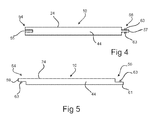
- Figure 4 depicts a cross section of a tile 10 through portion 44, where the side 54 is formed with a longitudinal groove 55 and the side 56 with a longitudinal and laterally extending tongue 57 that fits into the groove and forms a seal therewith.
- the side 54 is formed with a laterally extending lip 59 of one half the thickness of the photovoltaic tile 10 and extending flush with the surface 24, while the side 54 is provided with a complementary lip 61 also of half the thickness of the photovoltaic tile 10 but flush with a bottom surface of the carrier tile 12 so that the side 56 of one photovoltaic tile 10 can overlie the side 54 of an adjacent photovoltaic tile 10 to form a waterproof seal.
- the sealing effect in both arrangements may be enhanced by the provision of one or more rubber seals 63 acting between the tongue 57 and groove 59 in the first instance, and the overlying lips 61, 63 in the second instance.
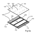
- FIGS 6a , 6b , 7 and 8 show in more detail an embodiment of the base tile assembly 100 to which one or more photovoltaic tiles 10 can be connected.
- the base tile 100 comprises a substrate 102 having a first (upper) surface 104, and an electrical connection system 200 supported by the substrate 102.
- the electrical connection system 200 comprises a plurality of conducting rails 202 that extend from side to side of the substrate 102 and one or more posts 204 each having a free end 206 that extends above the first surface 104.
- the substrate 102 comprises a bottom shell 110 having a planar bottom surface 112 and a peripheral wall 114 extending about the bottom surface 112.
- a cavity 116 is defined between the bottom surface 112 and the peripheral wall 114.
- the conducting rails 202 are disposed in the cavity 116.
- the substrate 102 also comprises a top shell 120 that overlies the cavity 116 and is sealed to the bottom shell 110.
- the top shell 120 is provided with a plurality of rows of holes 122 through which the free ends 206 of the posts 204 extend.
- the cavity 116 Prior to sealing the top shell 120 to the bottom shell 110, the cavity 116 may be filled with an insulating material to minimise heat transfer through the base tile 100.
- Opposite ends of the rails 202 are formed with complementary connectors so that the connectors at one end of a rail 202 in one base tile 100 can electrically connect with electrical connector of another rail 202 of an adjacent base tile 100. That is, the rails 202 in sideways adjacent base tiles 100 connect together to provide electrical continuity between sideways adjacent base tiles 100.
- This embodiment of the electrical connection system 200 provides for each base tile 100 three independent banks of parallel connected photovoltaic tiles 10, as depicted in the circuit diagram in Figure 6b . Each bank is electrically connected to an adjacent banks of an adjacent base tile 100. However as explained below different electrical connection systems may be incorporated in the base tile to provide electrical outputs.
- each photovoltaic tile 10 is provided with a pair of terminals 28 and 30.
- a plurality of photovoltaic tiles 10 can be connected to a base tile 100. This is achieved by aligning the terminals 28 and 30 of a photovoltaic tile 10 with the free end 206 of two laterally adjacent posts 204 extending above the surface 104.
- a first photovoltaic tile 10 could be coupled with the base tile 100 by pushing free ends 206a and 206b at the lower lefthand corner of the base tile assembly 100 through the holes 40 and 42 of a photovoltaic tile 10.
- the posts 204 are configured to electrically couple with the corresponding terminals 28 and 30 to provide electrical coupling with the photovoltaic cell 14 of that particular photovoltaic tile 10. Subsequently, an adjacent photovoltaic tile 10 in the same row as that previously laid is coupled to the next two laterally adjacent free ends 206. This process is continued for each row of photovoltaic tiles 10 so that the whole, or a portion of, a roof structure can be covered with photovoltaic tiles 10.
- the electricity generated by the photovoltaic cells 14 in each photovoltaic tile 10 is conducted through the posts 108 and rails 106 to remote electrical devices and apparatuses such as storage batteries, inverters, heaters, or other appliances.
- Figure 1 depicts a photovoltaic tile 10 with eighteen photovoltaic cells 14 arranged in a 3x6 matrix.
- Figures 3 and 6 depict a base tile 100 to which nine photovoltaic tiles 10 can be connected.
- the specific number of cells 14 per photovoltaic tile 10, and the manner in which the cells are connected within the tile 10, as well as the number of tiles 10 connected with each base tile 100 and the manner in which the tiles 10 are electrically connected is dependent on numerous design considerations. These include, but are not limited to:
- photovoltaic tiles 10 in accordance with the present embodiments of the invention are to be used to provide sufficient voltage to drive a common indoor grid inverter
- the cells 14 be combined in a manner to produce a maximum voltage in the order of 180 volts.
- a typical off-the-shelf multi-crystalline photovoltaic cell produces a maximum voltage of approximately .5 of a volt.
- the current produced is dependent upon the size or area of the cell.
- 180 volts clearly a number of cells 14 need to be connected in series. In determining the best way to produce a voltage of approximately 180 volts one needs to consider trade-offs between:
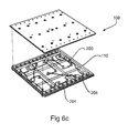
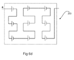
- FIG. 6c and 6d One specific configuration as shown in Figures 6c and 6d appears to be well suited to driving a typical indoor grid inverter having a MPPT range of 150+ volts comprises a tile 10 having an arrangement of nine photovoltaic cells 14 arranged in a 3x3 series connected matrix and where each base tile 100 carries nine series connected photovoltaic tiles 10.
- the electrical connection system differs from that shown in Figures 6a , 6b , and 7 as it provides a series connection between each of the photovoltaic tiles 10 as depicted in Figures 6c and 6d .
- each base tile 100 produces an output voltage of approximately 41 volts and a current of approximately 1.25amps.
- By connecting five base tiles 100 together in series an output voltage of approximately 180 volts is achieved.
- each base tile has dimensions of 600x600mm, then the area of a roof required to generate approximately 180 volts is 600x3000mm where five of the base tiles 100 are placed side by side.
- each photovoltaic tile 10 carries ten series connected photovoltaic cells 14 arranged in a 2x5 matrix and where each base tile 100 carries nine series connected tiles 10. In that event, each tile 10 produces approximately 5 volts, and thus each base tile 100 produces approximately 45 volts, in which case four series connected base tiles 100 are required to generate approximately 180 volts.
- each photovoltaic tile 10 may carry say 25 photovoltaic cells 14 arranged in a 5x5 matrix. In this case, each tile 10 would produce approximately 12.7 volts and thus each base tile 100 having nine series connected photovoltaic tiles 10 produces approximately 114 volts in which case two series connected base tiles 100 are required to achieve a 180 volt output.
- each photovoltaic tile 10 comprises a plurality of photovoltaic cells 14. This requires cutting and thus wastage of the cells.
- each photovoltaic tile may comprise a single uncut photovoltaic cell.
- each base tile With a parallel connection between the photovoltaic tiles on each base tile as depicted in Figures 6a and 6b , but with the banks connected in series, each base tile would produce an output voltage of approximately 4.6 volts and current of approximately 5.1 amps. Thus to achieve an output voltage of at least 180 volts forty series connected base tiles are required. But with the electrical connection as shown in Figures 6c and 6d , each base tile would produce an output voltage of approximately 0.5 volts and current of approximately 5.1 amps. Thus to achieve an output voltage of at least 180 volts one hundred and nineteen series connected base tiles are required.
- the carrier tile 12 is described and illustrated as comprising a single recess 20 for seating a single photovoltaic cell 14.
- multiple recesses may be formed each seating separate smaller photovoltaic cells.
- the terminals 28 and 30 are depicted as separate through hole terminals in the carrier tile 12.
- the terminals 28 and 30 may be formed concentrically with each other whereby electrical connection can be achieved by the use of a co-axial single pin connector.
- more than two terminals may be provided on a tile 10, for example, two positive and two negative terminals where the terminals of the same priority are connected in parallel to the photovoltaic cell 14. This provides a degree of redundancy in the event of the failure of one connector, as well as providing greater mechanical coupling of the photovoltaic tile 10 to a base tile 100.
Applications Claiming Priority (1)
| Application Number | Priority Date | Filing Date | Title |
|---|---|---|---|
| SG200806822-3A SG160244A1 (en) | 2008-09-15 | 2008-09-15 | Photovoltaic tile |
Publications (2)
| Publication Number | Publication Date |
|---|---|
| EP2180525A2 true EP2180525A2 (de) | 2010-04-28 |
| EP2180525A3 EP2180525A3 (de) | 2011-04-06 |
Family
ID=40580651
Family Applications (1)
| Application Number | Title | Priority Date | Filing Date |
|---|---|---|---|
| EP09153771A Withdrawn EP2180525A3 (de) | 2008-09-15 | 2009-02-26 | Photovoltaikfliese |
Country Status (13)
| Country | Link |
|---|---|
| US (1) | US20100065107A1 (de) |
| EP (1) | EP2180525A3 (de) |
| JP (1) | JP2010065522A (de) |
| KR (1) | KR20110079657A (de) |
| CN (1) | CN102272394A (de) |
| AU (1) | AU2009292238A1 (de) |
| CA (1) | CA2737117A1 (de) |
| GB (1) | GB2463335A (de) |
| IL (1) | IL211653A0 (de) |
| MX (1) | MX2011002740A (de) |
| SG (1) | SG160244A1 (de) |
| TW (1) | TW201018769A (de) |
| WO (1) | WO2010030246A2 (de) |
Cited By (2)
| Publication number | Priority date | Publication date | Assignee | Title |
|---|---|---|---|---|
| EP2565341A2 (de) | 2011-08-31 | 2013-03-06 | Integrasol | Vorrichtung zur Integration und Befestigung eine Fotovoltaikpaneels auf einem Dach |
| EP3154190A4 (de) * | 2014-06-06 | 2017-12-13 | Kaneka Corporation | Solarzellenmodul und dachstruktur |
Families Citing this family (19)
| Publication number | Priority date | Publication date | Assignee | Title |
|---|---|---|---|---|
| SG160243A1 (en) * | 2008-09-12 | 2010-04-29 | Dragon Energy Pte Ltd | An electrical connection system |
| WO2010068677A2 (en) * | 2008-12-09 | 2010-06-17 | Koch Steven A | Photovoltaic roofing elements, photovoltaic roofing systems, methods and kits |
| US8732940B2 (en) * | 2009-03-12 | 2014-05-27 | Clean Energy Solutions, Inc. | System and method for mounting photovoltaic panels |
| US20100325976A1 (en) * | 2009-06-25 | 2010-12-30 | Degenfelder Jeffrey G | Solar shingle system |
| US8511006B2 (en) * | 2009-07-02 | 2013-08-20 | Owens Corning Intellectual Capital, Llc | Building-integrated solar-panel roof element systems |
| US20120055550A1 (en) * | 2010-09-02 | 2012-03-08 | First Solar, Inc. | Solar module with light-transmissive edge seal |
| WO2012116306A1 (en) * | 2011-02-24 | 2012-08-30 | Rensselaer Polytechnic Institute | Energy exchanging building envelope |
| US8782972B2 (en) | 2011-07-14 | 2014-07-22 | Owens Corning Intellectual Capital, Llc | Solar roofing system |
| NL2008853C2 (nl) * | 2012-05-22 | 2013-11-25 | Mate4Sun B V | Zonnepaneelmodule en samenstel. |
| EP3022775A1 (de) * | 2013-07-19 | 2016-05-25 | Dow Global Technologies LLC | Kopplungssystem für fotovoltaikanordnungen |
| ES2528066B1 (es) * | 2013-08-02 | 2015-11-11 | José Alejandro MÉNDEZ CLEMENTE | Losa para cubierta de tejado |
| US9515599B2 (en) | 2013-09-17 | 2016-12-06 | Lumos Lsx, Llc | Photovoltaic panel mounting rail with integrated electronics |
| ES2611707B1 (es) * | 2015-11-05 | 2018-02-13 | Guillermo MADRIGAL BALLESTER | Placa solar ondulada modulable imitando la teja colocada |
| WO2018098580A1 (en) | 2016-12-01 | 2018-06-07 | Costain Roderick | Integrated solar building product panels |
| GB2576691B (en) * | 2018-05-22 | 2021-01-27 | Champion Mouldings Ltd | Solar roof tiles |
| DE102018131341A1 (de) * | 2018-12-07 | 2020-06-10 | Hanwha Q Cells Gmbh | Solarmodul und Photovoltaik-Anlage |
| GB201905849D0 (en) | 2019-04-26 | 2019-06-12 | Roof Tiles Tech Limited | Photovoltaic roof covering and method of manufacture |
| USD941231S1 (en) * | 2019-06-13 | 2022-01-18 | Morgan Solar Inc. | Solar panel |
| EP4229750A1 (de) * | 2020-10-14 | 2023-08-23 | Gaf Energy LLC | Montagevorrichtung für fotovoltaische module |
Family Cites Families (24)
| Publication number | Priority date | Publication date | Assignee | Title |
|---|---|---|---|---|
| DE2818474A1 (de) * | 1978-04-27 | 1979-10-31 | Bauer Geb Koerzdorfer Ingeborg | Dachabdeckung, sowie dazugehoerige anlage bzw. anordnung |
| DE2806810A1 (de) * | 1978-02-17 | 1979-08-23 | Werner Burde | Solardachplatte |
| US4830038A (en) * | 1988-01-20 | 1989-05-16 | Atlantic Richfield Company | Photovoltaic module |
| US5290366A (en) * | 1990-03-08 | 1994-03-01 | Siemens Solar Gmh | Laminated solar module |
| US5232518A (en) * | 1990-11-30 | 1993-08-03 | United Solar Systems Corporation | Photovoltaic roof system |
| EP0719459A1 (de) * | 1993-09-16 | 1996-07-03 | Blue Planet Ag | Solar-dachziegel/dachstein |
| US5590495A (en) * | 1995-07-06 | 1997-01-07 | Bressler Group Inc. | Solar roofing system |
| US5647915A (en) * | 1996-06-13 | 1997-07-15 | Zukerman; Charles | Solar energy panel |
| DE19704255C2 (de) * | 1997-02-05 | 2002-01-24 | Gerhard Wissing | Verfahren zum Herstellen eines Solardachziegels |
| WO2000030184A1 (en) * | 1998-11-13 | 2000-05-25 | Us Solar Roof | Photovoltaic roof tile |
| AUPQ236199A0 (en) * | 1999-08-20 | 1999-09-16 | Melbourne Equities Pty Ltd | Solar panel |
| DE20002827U1 (de) * | 2000-02-17 | 2000-05-04 | Roehm Gmbh | Photovoltaik-Element |
| JP2002124695A (ja) * | 2000-10-13 | 2002-04-26 | Sharp Corp | 太陽電池モジュールの設置構造及び設置方法 |
| JP3797871B2 (ja) * | 2000-12-05 | 2006-07-19 | シャープ株式会社 | 宇宙用ソーラーパネルおよびその修理方法 |
| WO2002101839A1 (en) * | 2001-06-11 | 2002-12-19 | Powertile Limited | Photovoltaic tiles |
| EP2242114B1 (de) * | 2001-09-28 | 2018-02-28 | Kaneka Corporation | Verfahren zum Legen von Solarzellenmodulen |
| AUPS038702A0 (en) * | 2002-02-08 | 2002-02-28 | Sustainable Technologies International | Construction products with integrated photovoltaics |
| US7342171B2 (en) * | 2003-01-23 | 2008-03-11 | Solar Intergrated Technologies, Inc. | Integrated photovoltaic roofing component and panel |
| US7645932B2 (en) * | 2003-09-10 | 2010-01-12 | Ixys Corporation | Solar cell device having a charge pump |
| EP1776720A4 (de) * | 2004-06-09 | 2008-07-09 | Redwood Renewables Llc | Entvulkanisierte photovoltaische dachziegel |
| US7642449B2 (en) * | 2004-08-24 | 2010-01-05 | General Electric Company | Photovoltaic integrated building component |
| US20060042683A1 (en) * | 2004-08-31 | 2006-03-02 | Ron Gangemi | System and method for mounting photovoltaic cells |
| WO2007035677A2 (en) * | 2005-09-19 | 2007-03-29 | Solar Roofing Systems, Inc. | Integrated solar roofing system |
| DE102006044418B3 (de) * | 2006-09-18 | 2007-12-06 | Solon AG für Solartechnik | Leichtgewichtiges Photovoltaiksystem in einer Ausbildung als Modulplatte |
-
2008
- 2008-09-15 SG SG200806822-3A patent/SG160244A1/en unknown
-
2009
- 2009-02-26 EP EP09153771A patent/EP2180525A3/de not_active Withdrawn
- 2009-03-04 GB GB0903763A patent/GB2463335A/en not_active Withdrawn
- 2009-04-29 US US12/432,505 patent/US20100065107A1/en not_active Abandoned
- 2009-06-12 JP JP2009140953A patent/JP2010065522A/ja active Pending
- 2009-09-08 TW TW098130193A patent/TW201018769A/zh unknown
- 2009-09-11 AU AU2009292238A patent/AU2009292238A1/en not_active Abandoned
- 2009-09-11 CA CA2737117A patent/CA2737117A1/en not_active Abandoned
- 2009-09-11 WO PCT/SG2009/000331 patent/WO2010030246A2/en active Application Filing
- 2009-09-11 MX MX2011002740A patent/MX2011002740A/es not_active Application Discontinuation
- 2009-09-11 KR KR1020117008728A patent/KR20110079657A/ko not_active Application Discontinuation
- 2009-09-11 CN CN2009801454511A patent/CN102272394A/zh active Pending
-
2011
- 2011-03-09 IL IL211653A patent/IL211653A0/en unknown
Cited By (3)
| Publication number | Priority date | Publication date | Assignee | Title |
|---|---|---|---|---|
| EP2565341A2 (de) | 2011-08-31 | 2013-03-06 | Integrasol | Vorrichtung zur Integration und Befestigung eine Fotovoltaikpaneels auf einem Dach |
| EP3154190A4 (de) * | 2014-06-06 | 2017-12-13 | Kaneka Corporation | Solarzellenmodul und dachstruktur |
| US10027275B2 (en) | 2014-06-06 | 2018-07-17 | Kaneka Corporation | Solar cell module and roof structure |
Also Published As
| Publication number | Publication date |
|---|---|
| JP2010065522A (ja) | 2010-03-25 |
| KR20110079657A (ko) | 2011-07-07 |
| SG160244A1 (en) | 2010-04-29 |
| WO2010030246A2 (en) | 2010-03-18 |
| CA2737117A1 (en) | 2010-03-18 |
| WO2010030246A3 (en) | 2013-02-28 |
| IL211653A0 (en) | 2011-05-31 |
| GB0903763D0 (en) | 2009-04-15 |
| EP2180525A3 (de) | 2011-04-06 |
| AU2009292238A1 (en) | 2010-03-18 |
| GB2463335A (en) | 2010-03-17 |
| US20100065107A1 (en) | 2010-03-18 |
| MX2011002740A (es) | 2011-08-12 |
| CN102272394A (zh) | 2011-12-07 |
| TW201018769A (en) | 2010-05-16 |
Similar Documents
| Publication | Publication Date | Title |
|---|---|---|
| EP2180525A2 (de) | Photovoltaikfliese | |
| EP2169727A1 (de) | Elektrische Solartafel | |
| US9786802B2 (en) | Photovoltaic roofing panels, photovoltaic roofing assemblies, and roofs using them | |
| US20090242015A1 (en) | Photovoltaic Roofing Elements, Laminates, Systems and Kits | |
| US8033857B2 (en) | Base tile | |
| US6928775B2 (en) | Multi-use electric tile modules | |
| US20090205270A1 (en) | Structured Photovoltaic Roofing Elements, Systems and Kits | |
| US20090120484A1 (en) | Photovoltaic Tile Assembly | |
| US9771719B2 (en) | Solar cell module-equipped panel and exterior building material using same | |
| MX2013011512A (es) | Sistema de panel solar integrado en techo con microinversores montados a los lados. | |
| AU723080B2 (en) | Solar cell system and method of establishing the system | |
| US9653634B2 (en) | Interlocking edges having electrical connectors for building integrable photovoltaic modules | |
| US8631613B1 (en) | Interlocking lips on building integrable photovoltaic module edges | |
| JPH08226210A (ja) | 太陽光発電用屋根材およびその施工方法 |
Legal Events
| Date | Code | Title | Description |
|---|---|---|---|
| PUAI | Public reference made under article 153(3) epc to a published international application that has entered the european phase |
Free format text: ORIGINAL CODE: 0009012 |
|
| 17P | Request for examination filed |
Effective date: 20090226 |
|
| AK | Designated contracting states |
Kind code of ref document: A2 Designated state(s): AT BE BG CH CY CZ DE DK EE ES FI FR GB GR HR HU IE IS IT LI LT LU LV MC MK MT NL NO PL PT RO SE SI SK TR |
|
| AX | Request for extension of the european patent |
Extension state: AL BA RS |
|
| PUAL | Search report despatched |
Free format text: ORIGINAL CODE: 0009013 |
|
| AK | Designated contracting states |
Kind code of ref document: A3 Designated state(s): AT BE BG CH CY CZ DE DK EE ES FI FR GB GR HR HU IE IS IT LI LT LU LV MC MK MT NL NO PL PT RO SE SI SK TR |
|
| AX | Request for extension of the european patent |
Extension state: AL BA RS |
|
| 17Q | First examination report despatched |
Effective date: 20110524 |
|
| AKY | No designation fees paid | ||
| REG | Reference to a national code |
Ref country code: DE Ref legal event code: R108 Effective date: 20111214 |
|
| RBV | Designated contracting states (corrected) |
Designated state(s): AT BE BG CH CY CZ DE DK EE ES FI FR GB GR HR HU IE IS IT LI LT LU LV MC MK MT NL NO PL PT RO SE SI SK TR |
|
| STAA | Information on the status of an ep patent application or granted ep patent |
Free format text: STATUS: THE APPLICATION IS DEEMED TO BE WITHDRAWN |
|
| 18D | Application deemed to be withdrawn |
Effective date: 20111206 |