EP2180297A2 - Rotation detector attachment decelerating device - Google Patents
Rotation detector attachment decelerating device Download PDFInfo
- Publication number
- EP2180297A2 EP2180297A2 EP20090013370 EP09013370A EP2180297A2 EP 2180297 A2 EP2180297 A2 EP 2180297A2 EP 20090013370 EP20090013370 EP 20090013370 EP 09013370 A EP09013370 A EP 09013370A EP 2180297 A2 EP2180297 A2 EP 2180297A2
- Authority
- EP
- European Patent Office
- Prior art keywords
- rotation
- shaft
- decelerating device
- decelerating
- pulley
- Prior art date
- Legal status (The legal status is an assumption and is not a legal conclusion. Google has not performed a legal analysis and makes no representation as to the accuracy of the status listed.)
- Granted
Links
- 230000000149 penetrating effect Effects 0.000 claims description 4
- 239000000314 lubricant Substances 0.000 claims description 3
- 238000007789 sealing Methods 0.000 claims description 2
- 238000001514 detection method Methods 0.000 description 10
- 230000004323 axial length Effects 0.000 description 3
- 230000005540 biological transmission Effects 0.000 description 3
- 230000002411 adverse Effects 0.000 description 1
- XAGFODPZIPBFFR-UHFFFAOYSA-N aluminium Chemical compound [Al] XAGFODPZIPBFFR-UHFFFAOYSA-N 0.000 description 1
- 229910052782 aluminium Inorganic materials 0.000 description 1
- 230000000694 effects Effects 0.000 description 1
- 238000000605 extraction Methods 0.000 description 1
- 238000003754 machining Methods 0.000 description 1
- 230000005389 magnetism Effects 0.000 description 1
- 238000000034 method Methods 0.000 description 1
- 230000010355 oscillation Effects 0.000 description 1
- 230000002093 peripheral effect Effects 0.000 description 1
Images


Classifications
-
- F—MECHANICAL ENGINEERING; LIGHTING; HEATING; WEAPONS; BLASTING
- F16—ENGINEERING ELEMENTS AND UNITS; GENERAL MEASURES FOR PRODUCING AND MAINTAINING EFFECTIVE FUNCTIONING OF MACHINES OR INSTALLATIONS; THERMAL INSULATION IN GENERAL
- F16H—GEARING
- F16H1/00—Toothed gearings for conveying rotary motion
- F16H1/28—Toothed gearings for conveying rotary motion with gears having orbital motion
- F16H1/32—Toothed gearings for conveying rotary motion with gears having orbital motion in which the central axis of the gearing lies inside the periphery of an orbital gear
-
- G—PHYSICS
- G01—MEASURING; TESTING
- G01D—MEASURING NOT SPECIALLY ADAPTED FOR A SPECIFIC VARIABLE; ARRANGEMENTS FOR MEASURING TWO OR MORE VARIABLES NOT COVERED IN A SINGLE OTHER SUBCLASS; TARIFF METERING APPARATUS; MEASURING OR TESTING NOT OTHERWISE PROVIDED FOR
- G01D5/00—Mechanical means for transferring the output of a sensing member; Means for converting the output of a sensing member to another variable where the form or nature of the sensing member does not constrain the means for converting; Transducers not specially adapted for a specific variable
- G01D5/12—Mechanical means for transferring the output of a sensing member; Means for converting the output of a sensing member to another variable where the form or nature of the sensing member does not constrain the means for converting; Transducers not specially adapted for a specific variable using electric or magnetic means
- G01D5/244—Mechanical means for transferring the output of a sensing member; Means for converting the output of a sensing member to another variable where the form or nature of the sensing member does not constrain the means for converting; Transducers not specially adapted for a specific variable using electric or magnetic means influencing characteristics of pulses or pulse trains; generating pulses or pulse trains
- G01D5/245—Mechanical means for transferring the output of a sensing member; Means for converting the output of a sensing member to another variable where the form or nature of the sensing member does not constrain the means for converting; Transducers not specially adapted for a specific variable using electric or magnetic means influencing characteristics of pulses or pulse trains; generating pulses or pulse trains using a variable number of pulses in a train
-
- G—PHYSICS
- G01—MEASURING; TESTING
- G01D—MEASURING NOT SPECIALLY ADAPTED FOR A SPECIFIC VARIABLE; ARRANGEMENTS FOR MEASURING TWO OR MORE VARIABLES NOT COVERED IN A SINGLE OTHER SUBCLASS; TARIFF METERING APPARATUS; MEASURING OR TESTING NOT OTHERWISE PROVIDED FOR
- G01D11/00—Component parts of measuring arrangements not specially adapted for a specific variable
- G01D11/30—Supports specially adapted for an instrument; Supports specially adapted for a set of instruments
-
- H—ELECTRICITY
- H02—GENERATION; CONVERSION OR DISTRIBUTION OF ELECTRIC POWER
- H02K—DYNAMO-ELECTRIC MACHINES
- H02K11/00—Structural association of dynamo-electric machines with electric components or with devices for shielding, monitoring or protection
-
- H—ELECTRICITY
- H02—GENERATION; CONVERSION OR DISTRIBUTION OF ELECTRIC POWER
- H02K—DYNAMO-ELECTRIC MACHINES
- H02K7/00—Arrangements for handling mechanical energy structurally associated with dynamo-electric machines, e.g. structural association with mechanical driving motors or auxiliary dynamo-electric machines
- H02K7/10—Structural association with clutches, brakes, gears, pulleys or mechanical starters
Definitions
- the present invention relates to a rotation detector attachment decelerating device.
- Patent Document 1 discloses a rotation detector attachment decelerating device G0 as shown in Fig. 7 .
- the decelerating device G0 is of a so-called eccentric oscillation internally meshing type, and includes a decelerating mechanism part having a first shaft 14 which is coaxially formed with an input shaft 12 so as to surround the input shaft 12; a second shaft 16 which is coaxially formed with the first shaft 14 so as to surround the first shaft 14; bearings 18 and 20 which are interposed between the first shaft 14 and the second shaft 16 so that one of the first and second shafts 14 and 16 is rotatably supported to the other thereof; and a decelerating mechanism 22 which decelerates the rotation input to the input shaft 12 and outputs the rotation from one of the first shaft 14 and the second shaft 16 in the state where the other of the first and second shafts 14 and 16 is fixed.
- a rotation detector 24 is interposed between the first and second shafts 14 and 16 so as to detect the rotation information of one of the first and second shafts 14 and 16 with respect to the other thereof.
- the rotation detector 24 is formed in a cylindrical shape, and includes an incremental-type code plate 26 which is formed in an outer peripheral surface 24a so as to record position information through magnetism; a detection portion 28 which detects the position information of the code plate 26 and outputs the position information by changing the position information into an electric signal; and an electronic unit 30 which processes the electric signal output from the detection portion 28.
- the code plate 26 is formed by a nonmagnetic body, for example, aluminum and a magnetic body which is coated on the outer periphery of the nonmagnetic body and has position information recorded thereon. The magnetic body having the position information recorded thereon is adapted so as not to directly come into contact with the first shaft 14.
- the rotation detector 24 having a particular structure such as a hollow structure has to be used. As a result, a problem arises in that the cost of the rotation detector extremely increases.
- the present invention is contrived to solve the above-described problems, and an object of the invention is to provide a rotation detector attachment decelerating device capable of using a low-cost (for example, a general-purpose) rotation detector.
- a rotation detector attachment decelerating device having a function of detecting a rotation of an output shaft
- the rotation detector attachment decelerating device including: an auxiliary rotation shaft which is disposed in parallel to the output shaft; rotation transmitting means for transmitting the rotation of the output shaft to the auxiliary rotation shaft; and a rotation detector which detects a rotation of the auxiliary rotation shaft, wherein the rotation of the output shaft is detected by detecting the rotation of the auxiliary rotation shaft using the rotation detector.
- the auxiliary rotation shaft is disposed in parallel to the output shaft of the decelerating device, the rotation is transmitted from the output shaft to the auxiliary rotation shaft, and then the rotation of the auxiliary rotation shaft is detected by the rotation detector, thereby detecting the rotation of the output shaft of the decelerating device.
- a rotation detector having a particular structure such as a hollow structure. That is, since it is possible to use, for example, a general-purpose detector at a low cost, it is possible to realize a decrease in cost of the decelerating device. Further, a highly precise general-purpose detector may be used depending on the use purpose, and in this case, it is possible to further improve the detection precision.
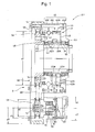
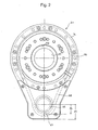
- Figs. 1 and 2 show an example of a rotation detector attachment decelerating device according to an embodiment of the invention.
- the decelerating device G1 has a decelerating portion (decelerating mechanism part) 32 of a so-called oscillation-type internally meshing planetary gear structure, and is formed as a hollow-type decelerating device which has a hollow portion H1 formed in a radial center portion of the decelerating portion 32 so as to penetrate therethrough.
- the decelerating device G1 includes an input shaft 36 which has the hollow portion H1; eccentric bodies 38A and 38B which are integrally formed with the input shaft 36; external tooth gears 42A and 42B which are respectively mounted to the outer peripheries of the eccentric bodies 38A and 38B through rollers 40A and 40B so as to be oscillatable and rotatable; and an internal tooth gear 44 with which the external tooth gears 42A and 42B internally mesh.
- the external tooth gears 42A and 42B and the internal tooth gear 44 have a slight difference in number of the teeth of gears (for example, "1").
- the internal tooth gear 44 is incorporated into a second casing 46B so as to be fixed thereto.
- the rotation components of the external tooth gears 42A and 42B are extracted from an output block 48, incorporated into an inner pin 45, through the inner pin 45.
- the input shaft 36 is supported to a first casing 46A and the output block 48 through a pair of bearings 54 and 55.
- the output block 48 is supported to third and fourth casings 46C and 46D through a cross roller 56.
- the connection between the output block 48 and the relative machine is carried out in such a manner that a bolt (not shown) is inserted into a bolt hole 48A of the output block 48 through a first pulley 64.
- the rotation detection system D includes an auxiliary rotation shaft 58 which serves as a detection target instead of the output block (output shaft) 48 and is disposed in parallel to the output block 48; rotation transmitting means 60 for transmitting the rotation of the output block 48 to the auxiliary rotation shaft 58; and a known encoder (rotation detector) 62 which detects the rotation of the auxiliary rotation shaft 58.
- the rotation transmitting means 60 is friction power transmitting means including the first pulley (a rotation body which rotates together with the output shaft) 64; a second pulley (a rotation member which rotates together with the auxiliary rotation shaft) 66; and a belt 68 which transmits the rotation of the first pulley 64 to the second pulley 66.
- the first pulley 64 is coaxially mounted to the output block 48 through a bolt 70.
- the first pulley 64 is formed as a hollow-type pulley which has a hollow portion H2 axially penetrating the radial center portion thereof, and the hollow portion H2 of the first pulley 64 is continuous to the hollow portion H1 of the decelerating device.
- the auxiliary rotation shaft 58 is disposed in parallel to the output block 48.
- the second pulley 66 is integrally mounted to the auxiliary rotation shaft 58 through a bolt 72, and the belt 68 connects the first pulley 64 to the second pulley 66 so that a power transmission therebetween can be carried out.
- An encoder casing 76 is integrally mounted to a pulley cover 74 which coats the first and second pulleys 64 and 66.
- the auxiliary rotation shaft 58 is rotatably supported to the encoder casing 76 in a cantilever state through bearings 78 and 80.
- an effective diameter d2 of the second pulley 66 is smaller than an effective diameter d1 (a diameter of a portion where the belt 68 is wound, that is, a pitch diameter) of the first pulley 64. That is, the rotation transmitting means 60 has a function of increasing the speed of the rotation of the output block 48 and transmitting the rotation to the auxiliary rotation shaft 58.
- a maximum diameter d3 in the circumference of the auxiliary rotation shaft 58 is set to be larger than a maximum diameter d4 of the second pulley 66.
- reference numerals 51 to 53 denote oil seals.
- the eccentric bodies 38A and 38B integrally formed with the input shaft 36 rotate.
- the eccentric bodies 38A and 38B rotate, the external tooth gears 42A and 42B mounted to the outer peripheries of the eccentric bodies 38A and 38B oscillatingly rotate through the rollers 40A and 40B.
- the internal tooth gear 44 is incorporated into the second casing 46B so as to be fixed thereto. For this reason, the free rotation of the external tooth gears 42A and 42B is restrained, and the external tooth gears 42A and 42B just oscillate. As a result, the meshing positions between the internal tooth gear 44 and the external tooth gears 42A and 42B are sequentially deviated in accordance with the rotation of the eccentric bodies 38A and 38B.
- a difference in number of teeth between the internal tooth gear 44 and the external tooth gears 42A and 42B is set to be a small value (for example, "1").
- the rotation components of the external tooth gears 42A and 42B are extracted in the form of the rotation of the output block 48 through the inner pin 45.
- the rotation of the output block 48 is directly changed to the rotation of the first pulley 64, and is transmitted to the second pulley 66 through the belt 68.
- the auxiliary rotation shaft 58 rotates, and the rotation is detected by the encoder 62. Since the effective diameter d2 of the second pulley 66 is smaller than the effective diameter d1 of the first pulley 64, the speed of the rotation of the output block 48 increases, and the rotation is transmitted to the auxiliary rotation shaft 58.
- the auxiliary rotation shaft 58 is installed inside the encoder casing 76 so as to be away from a casing 46 (46A to 46D) of the body portion of the decelerating device G1.
- the rotation of the output block 48 is transmitted to the auxiliary rotation shaft 58 through the belt 68 capable of absorbing the vibration. For this reason, even when the external tooth gears 42A and 42B oscillate at a high speed, the vibration of the external tooth gears 42A and 42B does not influence the auxiliary rotation shaft 58, and the speed of the rotation of the output block 48 is increased. Accordingly, a minute non-uniform rotation degree of the output block 48 can be amplified so as to be accurately obtained by the encoder 62.
- the rotation of the output block 48 is transmitted by the belt (friction power transmitting means) 68, the radial dimension of the decelerating device is reduced and the backlash hardly occurs in the decelerating device compared with the case where the power transmission is carried out by the gear. Accordingly, it is possible to improve the detection precision.
- the diameter of the auxiliary rotation shaft 58 is set in accordance with the diameter of the most common detection target shaft of the most common encoder 62, for example, it is possible to use a highly precise common encoder at a low cost.
- the auxiliary rotation shaft 58 is supported to the encoder casing 76 in a cantilever state, and the second pulley 66 is mounted to the auxiliary rotation shaft 58 in a cantilever state. For this reason, it is possible to minimally suppress that the axial length of the decelerating device G1 extends to the load side (the relative machine side) than the first and second pulleys 64 and 66.
- the maximum diameter d3 of the circumference of the auxiliary rotation shaft of the encoder casing 76 is set to be smaller than the minimum diameter d5 of the circumference of the second pulley 66 of the pulley cover 74, even when the encoder 62 exists, it is possible to minimally suppress the radial protruding amount of the decelerating device G1.
- the encoder 62 is offset from the axis of the decelerating portion 32 (compared with the case where the encoder and the decelerating portion are coaxially disposed), even when a leakage of a lubricant of the decelerating device G1 occurs, the lubricant does not have a negative influence on the encoder 62 (which is adversely influenced by oil).
- Figs. 3 and 4 show an example of the rotation detector attachment decelerating device according to another embodiment of the invention.
- the first casing 46A ( Fig. 1 ) of the decelerating device G1 is changed to fifth and sixth casings 46E and 46F having a shape capable accommodating a parallel shaft gear set 90. That is, a decelerating device G2 is obtained in such a manner that the decelerating device G1 further includes the parallel shaft gear set (front stage decelerating portion) 90 and the motor M1.
- the motor M1 is mounted to the sixth casing 46F.
- the motor M1 When the motor M1 is viewed in the axial direction thereof, the motor M1 almost overlaps with the encoder casing 76 (see Fig. 4 ).
- the encoder 62 can be mounted to a space, which can be a dead space in actual, (even when the encoder 62 does not exist), it is possible to prevent as much as possible the decelerating device from increasing in the radial direction due to the existence of the encoder 62.
- a spur pinion 96 is mounted to a motor shaft 92 of the motor M1 through a key 94.
- a spur gear 100 capable of meshing with the spur pinion 96, is mounted to the input shaft 36 through a bolt 98. The rotation of the motor shaft 92 of the motor M1 is input to the input shaft 36 through the spur pinion 96 and the spur gear 100.
- a protection pipe 102 is disposed in the hollow portion H1 of the decelerating device G1 and the hollow portion H2 of the first pulley 64.
- one end (in the example shown in the drawing, the opposite load-side end) 102A thereof is fixed to the sixth casing 46F of the decelerating device G2 through a bolt 103, and an oil seal 104 is disposed in the outer periphery of the other end (in the example shown in the drawing, a position corresponding to the inner periphery of the hollow portion H2 of the first pulley 64). Accordingly, for example, compared with the decelerating device G1 shown in Fig. 1 , the oil seal 53 may be omitted.
- the oil seal 104 is disposed between the fixed protection pipe 102 and the inner periphery 64A of the first low-speed pulley 64 (compared with the oil seal 52), it is possible to reduce the rotation loss and to improve the durability of the oil seal 104. Since the rotation speed relative to the seal is low, it is possible to improve the sealing property.
- This configuration is obtained by appropriately using the inner peripheries of the protection pipe 102 and the first pulley 64. Since the protection pipe 102 is disposed inside the hollow portions H1 and H2, even in the case where, for example, a wiring or the like passes through the hollow portions H1 and H2, it is possible to effectively prevent the damage of the wiring.
- the maximum diameter d7 of the second pulley 67 rotating together with the auxiliary rotation shaft 58 is smaller than the maximum diameter d3 of the encoder casing 76.
- the size of the general-purpose encoder casing 76 is set.
- the maximum diameter d7 of the second pulley 67 largely influences the minimum diameter d6 of the circumference of the auxiliary shaft of the pulley cover 75.
- the maximum diameter d7 of the second pulley 67 is set to be smaller than the maximum diameter d3 of the encoder casing 76 (in short, for example, when the encoder casing 76 in use is small, the maximum diameter d7 of the second pulley 67 is set to be small in accordance with the size of the encoder casing 76), it is possible to allow the minimum diameter d6 of the circumference of the auxiliary shaft of the pulley cover 75 to be smaller than the maximum diameter d3 of the encoder casing 76 (or it is possible to allow the minimum diameter d6 not to be excessively larger than the maximum diameter d3), and thus to suppress the entire radial dimension of the decelerating device to be small.
- the input shaft 36 exists at the center portion of the decelerating device G1 (G2), and the decelerating device G1 (G2) of the internally meshing planetary gear mechanism is employed in which the external tooth gears 42A and 42B oscillate by the eccentric bodies 38A and 38B formed in the outer periphery of the input shaft 36, but in the invention, the particular configuration of the decelerating device is not particularly limited. Further, the configuration in which the power is input from the motor to the decelerating device is not particularly limited to the above-described embodiment.
- Fig. 6 is an enlarged view showing a main part in Fig. 5 .
- an output of a motor shaft 110 of a motor M2 is transmitted to a pinion shaft 114 via a connection member 112.
- the pinion shaft 114 is supported to a connection casing 120 by a pair of bearings 116 and 118.
- a spur pinion 122 is formed in the front end of the pinion shaft 114 by cutting.
- the spur pinion 122 meshes with a spur gear 124.
- the spur gear 124 is continuous to a cylindrical portion 126 having a hollow port H3, and a center gear 128 having a dimension smaller than that of the spur gear 124 is formed in a part of the outer periphery of the cylindrical portion 126.
- Three distribution gears 130 (in Figs. 5 and 6 , only one of the three distribution gears is shown) mesh with the center gear 128, and three eccentric body shafts 132 (in Fig. 6 , only one of the three eccentric body shafts is shown) are simultaneously driven.
- Eccentric bodies 134A and 134B are integrally formed with each eccentric body shaft 132.
- eccentric bodies 134A and 134B of each eccentric body shaft 132 rotate at the same phase, external tooth gears 136A and 136B oscillate.
- the external tooth gears 136A and 136B oscillate once and rotate by an amount corresponding to the difference in the number of teeth of the internal tooth gear 138 whenever each eccentric body shaft 132 rotates once.
- This rotation is extracted from a carrier 140 in the form of the revolution about the axis 03 of the decelerating device G2 having three eccentric body shafts 132. That is, in the decelerating device G2, the carrier 140 corresponds to the output member.
- a first pulley 142 is fixed to the carrier 140 through a bolt 144, and an auxiliary rotation shaft 150 rotates through a second pulley 146 and the belt 148 in the same manner as described above.
- the rotation of the auxiliary rotation shaft 150 is detected by an encoder 152.
- the configuration and the effect including the rotation of the carrier 140 as the output member of the first pulley 142, the transmission through the belt 148, the rotation of the second pulley 146, the rotation of the auxiliary' rotation shaft 150, and the rotation detection through the encoder 153 are the same as those of the above-described embodiment.
- the decelerating mechanism part is formed as a large-diameter hollow structure.
- the encoder 152 just detects the rotation of the small-diameter auxiliary rotation shaft 150, it is possible to use the highly precise general-purpose encoder 152 at a low cost.
- first pulley, the belt, the second pulley, the auxiliary rotation shaft, the encoder, and the encoder casing used in the above-described embodiment can be commonly used upon being mounted to the output shafts of various decelerating devices.
- the input shaft and the output shaft are coaxially disposed or the input shaft is formed as a hollow structure
- a rotation detector having a particular structure such as a hollow structure. That is, since it is possible to use, for example, a general-purpose detector at a low cost, it is possible to realize a decrease in cost of the decelerating device. Further, a highly precise general-purpose detector may be used depending on the application, and in this case, it is possible to further improve the detection precision.
- the motor may be disposed so as not to overlap with the rotation detector when seen in the axial direction of the motor. Since the rotation detector such as the encoder is a delicate component, the rotation detector may be comparatively frequently broken. Accordingly, with such a configuration, it is advantageous in that the rotation detector can be easily exchanged.
- the motor does not overlap with the rotation detector, but an axial extraction space for the rotation detector is ensured. For this reason, it is easy to exchange the rotation detector.
- the decelerating device having the hollow-type decelerating mechanism part is exemplified.
- the invention is not limited to the decelerating device having the hollow-type decelerating mechanism part.
- a decelerating device without a hollow portion may be used.
- a decelerating device having coaxial input and output shafts may be used.
- the configuration of the decelerating mechanism part of the decelerating device is not limited to the configuration according to the above-described embodiment.
- a decelerating mechanism part of a simple planetary gear structure may be used, or a decelerating mechanism of a so-called bending-meshing planetary gear structure may be used.
- the friction power transmitting means having the pulley and the belt is employed as the rotation transmitting means.
- the rotation transmitting means using a gear mechanism may be employed.
- the end of the cover (74) may extend inward in the radial direction instead of the oil seal 51, and an oil seal may be disposed so as to seal the extended portion and the axial end surface of the gear. Accordingly, it is possible to satisfactorily lubricate the gear portion of the gear.
- the rotation transmitting means is formed by the gear mechanism, it is possible to minimally reduce the axial length of the rotation transmitting means, and thus to further reduce the entire axial length of the decelerating device.
- the invention is particularly suitable for a closed control or the like of a robot or a machining tool.
Landscapes
- Engineering & Computer Science (AREA)
- Physics & Mathematics (AREA)
- General Physics & Mathematics (AREA)
- Power Engineering (AREA)
- General Engineering & Computer Science (AREA)
- Mechanical Engineering (AREA)
- Retarders (AREA)
- General Details Of Gearings (AREA)
- Transmission And Conversion Of Sensor Element Output (AREA)
- Machine Tool Sensing Apparatuses (AREA)
- Testing Of Balance (AREA)
Abstract
Description
- The present invention relates to a rotation detector attachment decelerating device.
- Priority is claimed on Japanese Patent Application No.
2008-274472, filed October 24, 2008 - For example,
Patent Document 1 discloses a rotation detector attachment decelerating device G0 as shown inFig. 7 . The decelerating device G0 is of a so-called eccentric oscillation internally meshing type, and includes a decelerating mechanism part having afirst shaft 14 which is coaxially formed with aninput shaft 12 so as to surround theinput shaft 12; asecond shaft 16 which is coaxially formed with thefirst shaft 14 so as to surround thefirst shaft 14;bearings first shaft 14 and thesecond shaft 16 so that one of the first andsecond shafts decelerating mechanism 22 which decelerates the rotation input to theinput shaft 12 and outputs the rotation from one of thefirst shaft 14 and thesecond shaft 16 in the state where the other of the first andsecond shafts - In the decelerating device G0, a
rotation detector 24 is interposed between the first andsecond shafts second shafts - The
rotation detector 24 is formed in a cylindrical shape, and includes an incremental-type code plate 26 which is formed in an outerperipheral surface 24a so as to record position information through magnetism; adetection portion 28 which detects the position information of thecode plate 26 and outputs the position information by changing the position information into an electric signal; and anelectronic unit 30 which processes the electric signal output from thedetection portion 28. In addition, thecode plate 26 is formed by a nonmagnetic body, for example, aluminum and a magnetic body which is coated on the outer periphery of the nonmagnetic body and has position information recorded thereon. The magnetic body having the position information recorded thereon is adapted so as not to directly come into contact with thefirst shaft 14.
[Patent Document 1] Japanese Patent Application Laid-Open No.2001-99245 - However, in the above-described decelerating device G0, since it is necessary to avoid the interference with the input shaft and to correspond to the hollow structure of the decelerating device, the
rotation detector 24 having a particular structure such as a hollow structure has to be used. As a result, a problem arises in that the cost of the rotation detector extremely increases. - The present invention is contrived to solve the above-described problems, and an object of the invention is to provide a rotation detector attachment decelerating device capable of using a low-cost (for example, a general-purpose) rotation detector.
- The above-described object is achieved by a rotation detector attachment decelerating device having a function of detecting a rotation of an output shaft, the rotation detector attachment decelerating device including: an auxiliary rotation shaft which is disposed in parallel to the output shaft; rotation transmitting means for transmitting the rotation of the output shaft to the auxiliary rotation shaft; and a rotation detector which detects a rotation of the auxiliary rotation shaft, wherein the rotation of the output shaft is detected by detecting the rotation of the auxiliary rotation shaft using the rotation detector.
- In the invention, the auxiliary rotation shaft is disposed in parallel to the output shaft of the decelerating device, the rotation is transmitted from the output shaft to the auxiliary rotation shaft, and then the rotation of the auxiliary rotation shaft is detected by the rotation detector, thereby detecting the rotation of the output shaft of the decelerating device. For this reason, for example, even in the case where the input shaft and the output shaft are coaxially disposed or the input shaft is formed as a hollow structure, it is not necessary to use a rotation detector having a particular structure such as a hollow structure. That is, since it is possible to use, for example, a general-purpose detector at a low cost, it is possible to realize a decrease in cost of the decelerating device. Further, a highly precise general-purpose detector may be used depending on the use purpose, and in this case, it is possible to further improve the detection precision.
- According to the invention, it is possible to detect the rotation of the output shaft of the decelerating device at a low cost.
-
-
Fig. 1 is a sectional view showing a rotation detector attachment decelerating device according to an embodiment of the invention. -
Fig. 2 is a side view showing the decelerating device. -
Fig. 3 is a sectional view showing the rotation detector attachment decelerating device according to another embodiment of the invention. -
Fig. 4 is a side view showing the decelerating device. -
Fig. 5 is a sectional view showing the rotation detector attachment decelerating device according to still another embodiment of the invention. -
Fig. 6 is an enlarged sectional view showing a main part of the rotation detector attachment decelerating device shown inFig. 5 . -
Fig. 7 is a sectional view showing the known rotation detector attachment decelerating device. - Hereinafter, an embodiment of the invention will be described in detail with reference to the accompanying drawings.
-
Figs. 1 and2 show an example of a rotation detector attachment decelerating device according to an embodiment of the invention. - The decelerating device G1 has a decelerating portion (decelerating mechanism part) 32 of a so-called oscillation-type internally meshing planetary gear structure, and is formed as a hollow-type decelerating device which has a hollow portion H1 formed in a radial center portion of the decelerating
portion 32 so as to penetrate therethrough. - The decelerating device G1 includes an
input shaft 36 which has the hollow portion H1;eccentric bodies input shaft 36;external tooth gears eccentric bodies rollers internal tooth gear 44 with which theexternal tooth gears - The
external tooth gears internal tooth gear 44 have a slight difference in number of the teeth of gears (for example, "1"). - The
internal tooth gear 44 is incorporated into a second casing 46B so as to be fixed thereto. In addition, the rotation components of theexternal tooth gears output block 48, incorporated into aninner pin 45, through theinner pin 45. Theinput shaft 36 is supported to afirst casing 46A and theoutput block 48 through a pair ofbearings - The
output block 48 is supported to third andfourth casings cross roller 56. The connection between theoutput block 48 and the relative machine is carried out in such a manner that a bolt (not shown) is inserted into a bolt hole 48A of theoutput block 48 through afirst pulley 64. - Here, a rotation detection system D for detecting the rotation (in detail, the rotation angle and the rotation direction) of the output block (output shaft) 48 of the decelerating device G1 will be described in detail.
- The rotation detection system D includes an
auxiliary rotation shaft 58 which serves as a detection target instead of the output block (output shaft) 48 and is disposed in parallel to theoutput block 48;rotation transmitting means 60 for transmitting the rotation of theoutput block 48 to theauxiliary rotation shaft 58; and a known encoder (rotation detector) 62 which detects the rotation of theauxiliary rotation shaft 58. - The rotation transmitting means 60 is friction power transmitting means including the first pulley (a rotation body which rotates together with the output shaft) 64; a second pulley (a rotation member which rotates together with the auxiliary rotation shaft) 66; and a
belt 68 which transmits the rotation of thefirst pulley 64 to thesecond pulley 66. - The
first pulley 64 is coaxially mounted to theoutput block 48 through abolt 70. Thefirst pulley 64 is formed as a hollow-type pulley which has a hollow portion H2 axially penetrating the radial center portion thereof, and the hollow portion H2 of thefirst pulley 64 is continuous to the hollow portion H1 of the decelerating device. - In the decelerating device G1, the
auxiliary rotation shaft 58 is disposed in parallel to theoutput block 48. Thesecond pulley 66 is integrally mounted to theauxiliary rotation shaft 58 through abolt 72, and thebelt 68 connects thefirst pulley 64 to thesecond pulley 66 so that a power transmission therebetween can be carried out. - An
encoder casing 76 is integrally mounted to apulley cover 74 which coats the first andsecond pulleys auxiliary rotation shaft 58 is rotatably supported to theencoder casing 76 in a cantilever state throughbearings second pulley 66 is smaller than an effective diameter d1 (a diameter of a portion where thebelt 68 is wound, that is, a pitch diameter) of thefirst pulley 64. That is, the rotation transmitting means 60 has a function of increasing the speed of the rotation of theoutput block 48 and transmitting the rotation to theauxiliary rotation shaft 58. In theencoder casing 76, a maximum diameter d3 in the circumference of theauxiliary rotation shaft 58 is set to be larger than a maximum diameter d4 of thesecond pulley 66. - In addition, the
reference numerals 51 to 53 denote oil seals. - Next, the action of the rotation detector attachment decelerating device G1 will be described.
- When the
input shaft 36 rotates, theeccentric bodies input shaft 36 rotate. When theeccentric bodies external tooth gears eccentric bodies rollers internal tooth gear 44 is incorporated into the second casing 46B so as to be fixed thereto. For this reason, the free rotation of theexternal tooth gears external tooth gears internal tooth gear 44 and theexternal tooth gears eccentric bodies internal tooth gear 44 and theexternal tooth gears input shaft 36 rotates once, theexternal tooth gears external tooth gears internal tooth gear 44 by an amount corresponding to the difference in number of teeth. - The rotation components of the
external tooth gears output block 48 through theinner pin 45. - The rotation of the
output block 48 is directly changed to the rotation of thefirst pulley 64, and is transmitted to thesecond pulley 66 through thebelt 68. When thesecond pulley 66 rotates, theauxiliary rotation shaft 58 rotates, and the rotation is detected by theencoder 62. Since the effective diameter d2 of thesecond pulley 66 is smaller than the effective diameter d1 of thefirst pulley 64, the speed of the rotation of theoutput block 48 increases, and the rotation is transmitted to theauxiliary rotation shaft 58. In addition, theauxiliary rotation shaft 58 is installed inside theencoder casing 76 so as to be away from a casing 46 (46A to 46D) of the body portion of the decelerating device G1. Then, in the embodiment, the rotation of theoutput block 48 is transmitted to theauxiliary rotation shaft 58 through thebelt 68 capable of absorbing the vibration. For this reason, even when the external tooth gears 42A and 42B oscillate at a high speed, the vibration of the external tooth gears 42A and 42B does not influence theauxiliary rotation shaft 58, and the speed of the rotation of theoutput block 48 is increased. Accordingly, a minute non-uniform rotation degree of theoutput block 48 can be amplified so as to be accurately obtained by theencoder 62. In addition, since the rotation of theoutput block 48 is transmitted by the belt (friction power transmitting means) 68, the radial dimension of the decelerating device is reduced and the backlash hardly occurs in the decelerating device compared with the case where the power transmission is carried out by the gear. Accordingly, it is possible to improve the detection precision. - Since the diameter of the
auxiliary rotation shaft 58 is set in accordance with the diameter of the most common detection target shaft of the mostcommon encoder 62, for example, it is possible to use a highly precise common encoder at a low cost. In addition, theauxiliary rotation shaft 58 is supported to theencoder casing 76 in a cantilever state, and thesecond pulley 66 is mounted to theauxiliary rotation shaft 58 in a cantilever state. For this reason, it is possible to minimally suppress that the axial length of the decelerating device G1 extends to the load side (the relative machine side) than the first andsecond pulleys - In addition, since the maximum diameter d3 of the circumference of the auxiliary rotation shaft of the
encoder casing 76 is set to be smaller than the minimum diameter d5 of the circumference of thesecond pulley 66 of thepulley cover 74, even when theencoder 62 exists, it is possible to minimally suppress the radial protruding amount of the decelerating device G1. - Further, since the
encoder 62 is offset from the axis of the decelerating portion 32 (compared with the case where the encoder and the decelerating portion are coaxially disposed), even when a leakage of a lubricant of the decelerating device G1 occurs, the lubricant does not have a negative influence on the encoder 62 (which is adversely influenced by oil). - Next,
Figs. 3 and4 show an example of the rotation detector attachment decelerating device according to another embodiment of the invention. - In this example, in order to connect a motor M1 to the decelerating device G1, the
first casing 46A (Fig. 1 ) of the decelerating device G1 is changed to fifth andsixth casings - The motor M1 is mounted to the
sixth casing 46F. When the motor M1 is viewed in the axial direction thereof, the motor M1 almost overlaps with the encoder casing 76 (seeFig. 4 ). With this configuration, since theencoder 62 can be mounted to a space, which can be a dead space in actual, (even when theencoder 62 does not exist), it is possible to prevent as much as possible the decelerating device from increasing in the radial direction due to the existence of theencoder 62. - A
spur pinion 96 is mounted to amotor shaft 92 of the motor M1 through a key 94. In addition, aspur gear 100, capable of meshing with thespur pinion 96, is mounted to theinput shaft 36 through abolt 98. The rotation of themotor shaft 92 of the motor M1 is input to theinput shaft 36 through thespur pinion 96 and thespur gear 100. - In addition, a
protection pipe 102 is disposed in the hollow portion H1 of the decelerating device G1 and the hollow portion H2 of thefirst pulley 64. In theprotection pipe 102, one end (in the example shown in the drawing, the opposite load-side end) 102A thereof is fixed to thesixth casing 46F of the decelerating device G2 through abolt 103, and anoil seal 104 is disposed in the outer periphery of the other end (in the example shown in the drawing, a position corresponding to the inner periphery of the hollow portion H2 of the first pulley 64). Accordingly, for example, compared with the decelerating device G1 shown inFig. 1 , theoil seal 53 may be omitted. In addition, theoil seal 104 is disposed between the fixedprotection pipe 102 and theinner periphery 64A of the first low-speed pulley 64 (compared with the oil seal 52), it is possible to reduce the rotation loss and to improve the durability of theoil seal 104. Since the rotation speed relative to the seal is low, it is possible to improve the sealing property. This configuration is obtained by appropriately using the inner peripheries of theprotection pipe 102 and thefirst pulley 64. Since theprotection pipe 102 is disposed inside the hollow portions H1 and H2, even in the case where, for example, a wiring or the like passes through the hollow portions H1 and H2, it is possible to effectively prevent the damage of the wiring. - Further, the maximum diameter d7 of the
second pulley 67 rotating together with theauxiliary rotation shaft 58 is smaller than the maximum diameter d3 of theencoder casing 76. In many cases, the size of the general-purpose encoder casing 76 is set. Meanwhile, the maximum diameter d7 of thesecond pulley 67 largely influences the minimum diameter d6 of the circumference of the auxiliary shaft of thepulley cover 75. Likewise, since the maximum diameter d7 of thesecond pulley 67 is set to be smaller than the maximum diameter d3 of the encoder casing 76 (in short, for example, when theencoder casing 76 in use is small, the maximum diameter d7 of thesecond pulley 67 is set to be small in accordance with the size of the encoder casing 76), it is possible to allow the minimum diameter d6 of the circumference of the auxiliary shaft of the pulley cover 75 to be smaller than the maximum diameter d3 of the encoder casing 76 (or it is possible to allow the minimum diameter d6 not to be excessively larger than the maximum diameter d3), and thus to suppress the entire radial dimension of the decelerating device to be small. - In the above-described embodiment, the
input shaft 36 exists at the center portion of the decelerating device G1 (G2), and the decelerating device G1 (G2) of the internally meshing planetary gear mechanism is employed in which the external tooth gears 42A and 42B oscillate by theeccentric bodies input shaft 36, but in the invention, the particular configuration of the decelerating device is not particularly limited. Further, the configuration in which the power is input from the motor to the decelerating device is not particularly limited to the above-described embodiment. - For example, the invention may be applied to the decelerating device having the configuration shown in
Figs. 5 and6 . In addition,Fig. 6 is an enlarged view showing a main part inFig. 5 . - In the examples shown in
Figs. 5 and6 , an output of amotor shaft 110 of a motor M2 is transmitted to apinion shaft 114 via aconnection member 112. Thepinion shaft 114 is supported to aconnection casing 120 by a pair ofbearings spur pinion 122 is formed in the front end of thepinion shaft 114 by cutting. Thespur pinion 122 meshes with aspur gear 124. Thespur gear 124 is continuous to acylindrical portion 126 having a hollow port H3, and acenter gear 128 having a dimension smaller than that of thespur gear 124 is formed in a part of the outer periphery of thecylindrical portion 126. Three distribution gears 130 (inFigs. 5 and6 , only one of the three distribution gears is shown) mesh with thecenter gear 128, and three eccentric body shafts 132 (inFig. 6 , only one of the three eccentric body shafts is shown) are simultaneously driven. -
Eccentric bodies 134A and 134B are integrally formed with eacheccentric body shaft 132. When theeccentric bodies 134A and 134B of eacheccentric body shaft 132 rotate at the same phase, external tooth gears 136A and 136B oscillate. In the example, since theinternal tooth gear 138 is fixed, the external tooth gears 136A and 136B oscillate once and rotate by an amount corresponding to the difference in the number of teeth of theinternal tooth gear 138 whenever eacheccentric body shaft 132 rotates once. This rotation is extracted from acarrier 140 in the form of the revolution about theaxis 03 of the decelerating device G2 having threeeccentric body shafts 132. That is, in the decelerating device G2, thecarrier 140 corresponds to the output member. - A
first pulley 142 is fixed to thecarrier 140 through abolt 144, and anauxiliary rotation shaft 150 rotates through asecond pulley 146 and thebelt 148 in the same manner as described above. The rotation of theauxiliary rotation shaft 150 is detected by anencoder 152. - The configuration and the effect including the rotation of the
carrier 140 as the output member of thefirst pulley 142, the transmission through thebelt 148, the rotation of thesecond pulley 146, the rotation of the auxiliary'rotation shaft 150, and the rotation detection through the encoder 153 are the same as those of the above-described embodiment. - Even in the embodiment, the decelerating mechanism part is formed as a large-diameter hollow structure. However, since the
encoder 152 just detects the rotation of the small-diameterauxiliary rotation shaft 150, it is possible to use the highly precise general-purpose encoder 152 at a low cost. - Further, most of the first pulley, the belt, the second pulley, the auxiliary rotation shaft, the encoder, and the encoder casing used in the above-described embodiment can be commonly used upon being mounted to the output shafts of various decelerating devices.
- Likewise, according to the invention, even in the case where the input shaft and the output shaft are coaxially disposed or the input shaft is formed as a hollow structure, it is not necessary to use a rotation detector having a particular structure such as a hollow structure. That is, since it is possible to use, for example, a general-purpose detector at a low cost, it is possible to realize a decrease in cost of the decelerating device. Further, a highly precise general-purpose detector may be used depending on the application, and in this case, it is possible to further improve the detection precision.
- In the above-described embodiments, it is possible to efficiently use a dead space formed by the decelerating device and the motor by overlapping the motor with at least a part of the rotation detector when seen in the axial direction of the motor. However, for example, the motor may be disposed so as not to overlap with the rotation detector when seen in the axial direction of the motor. Since the rotation detector such as the encoder is a delicate component, the rotation detector may be comparatively frequently broken. Accordingly, with such a configuration, it is advantageous in that the rotation detector can be easily exchanged.
- Further, in the example shown in
Fig. 5 , the motor does not overlap with the rotation detector, but an axial extraction space for the rotation detector is ensured. For this reason, it is easy to exchange the rotation detector. - In the above-described embodiments, the decelerating device having the hollow-type decelerating mechanism part is exemplified. However, the invention is not limited to the decelerating device having the hollow-type decelerating mechanism part. For example, a decelerating device without a hollow portion may be used. In addition, a decelerating device having coaxial input and output shafts may be used.
- The configuration of the decelerating mechanism part of the decelerating device is not limited to the configuration according to the above-described embodiment. For example, a decelerating mechanism part of a simple planetary gear structure may be used, or a decelerating mechanism of a so-called bending-meshing planetary gear structure may be used.
- In the above-described embodiments, the friction power transmitting means having the pulley and the belt is employed as the rotation transmitting means. However, for example, the rotation transmitting means using a gear mechanismmay be employed. In this case, for example, as shown in the example in
Fig. 1 (orFigs. 3 and5 ), the end of the cover (74) may extend inward in the radial direction instead of theoil seal 51, and an oil seal may be disposed so as to seal the extended portion and the axial end surface of the gear. Accordingly, it is possible to satisfactorily lubricate the gear portion of the gear. In the case where the rotation transmitting means is formed by the gear mechanism, it is possible to minimally reduce the axial length of the rotation transmitting means, and thus to further reduce the entire axial length of the decelerating device. - Since it is not necessary to prepare a particular rotation detector having, for example, a large-diameter hollow portion upon detecting the rotation speed of the output shaft of the decelerating device, the invention is particularly suitable for a closed control or the like of a robot or a machining tool.
Claims (7)
- A rotation detector attachment decelerating device having a function of detecting a rotation of an output shaft, the rotation detector attachment decelerating device comprising:an auxiliary rotation shaft which is disposed in parallel to the output shaft;rotation transmitting means for transmitting the rotation of the output shaft to the auxiliary rotation shaft; anda rotation detector which detects a rotation of the auxiliary rotation shaft,wherein the rotation of the output shaft is detected by detecting the rotation of the auxiliary rotation shaft using the rotation detector.
- The rotation detector attachment decelerating device according to claim 1,
wherein the rotation transmitting means includes a first pulley which is mounted to the output shaft, a second pulley which is mounted to the auxiliary rotation shaft, and a belt which connects the first pulley to the second pulley. - The rotation detector attachment decelerating device according to claim 2,
wherein an effective diameter of the second pulley is smaller than that of the first pulley. - The rotation detector attachment decelerating device according to any one of claims 1 to 3,
wherein the auxiliary rotation shaft is supported in a cantilever manner by a bearing disposed in a casing of the rotation detector. - The rotation detector attachment decelerating device according to any one of claims 1 to 4,
wherein the rotation transmittingmeans includes a rotation body which rotates together with the auxiliary rotation shaft, and a maximum diameter of the rotation body is smaller than that of the rotation detector. - The rotation detector attachment decelerating device according to any one of claims 1 to 5,
wherein a decelerating mechanism part of the decelerating device is formed as a hollow-type decelerating mechanism part which has a hollow portion axially penetrating a radial center portion thereof, and a rotation body of the rotation transmitting means rotating together with the output shaft is formed as a hollow-type rotation body which has a hollow portion axially penetrating a radial center portion thereof,
wherein a protection pipe is disposed from the hollow portion of the decelerating device to the hollow portion of the rotation body, and
wherein a part of the protection pipe is fixed to a casing of the decelerating device, and an oil seal for sealing a lubricant of the decelerating device is disposed between the other part of the protection pipe and the inner periphery of the hollow portion of the rotation body. - The rotation detector attachment decelerating device according to any one of claims 1 to 6,
wherein the decelerating device includes a motor which supplies driving force to the decelerating mechanism part,
wherein the decelerating mechanism part is formed as the hollow-type decelerating mechanism part which has the hollow portion axially penetrating the radial center portion thereof,
wherein an axis of the motor is offset from an axis of the hollow portion of the decelerating mechanism part, and
wherein the motor overlaps with at least a part of the rotation detector when seen in the axial direction of the motor.
Applications Claiming Priority (1)
| Application Number | Priority Date | Filing Date | Title |
|---|---|---|---|
| JP2008274472A JP5130184B2 (en) | 2008-10-24 | 2008-10-24 | Reducer with rotation detector |
Publications (4)
| Publication Number | Publication Date |
|---|---|
| EP2180297A2 true EP2180297A2 (en) | 2010-04-28 |
| EP2180297A3 EP2180297A3 (en) | 2014-03-05 |
| EP2180297B1 EP2180297B1 (en) | 2016-03-23 |
| EP2180297B8 EP2180297B8 (en) | 2016-07-13 |
Family
ID=41568520
Family Applications (1)
| Application Number | Title | Priority Date | Filing Date |
|---|---|---|---|
| EP09013370.3A Active EP2180297B8 (en) | 2008-10-24 | 2009-10-22 | Rotation detector attachment decelerating device |
Country Status (4)
| Country | Link |
|---|---|
| EP (1) | EP2180297B8 (en) |
| JP (1) | JP5130184B2 (en) |
| KR (1) | KR101123110B1 (en) |
| CN (1) | CN101725688B (en) |
Families Citing this family (5)
| Publication number | Priority date | Publication date | Assignee | Title |
|---|---|---|---|---|
| CN102645240A (en) * | 2012-04-28 | 2012-08-22 | 浙江恒立数控科技股份有限公司 | Installation structure of encoder |
| JP6017969B2 (en) * | 2013-01-09 | 2016-11-02 | トヨタ自動車株式会社 | Operating angle measuring device and operating angle measuring method for variable valve timing mechanism |
| JP6336296B2 (en) * | 2014-02-28 | 2018-06-06 | 三菱重工業株式会社 | Engine rotation sensor device, marine engine equipped with the same |
| JP6941936B2 (en) * | 2016-12-05 | 2021-09-29 | 住友重機械工業株式会社 | Decelerator |
| JP7846517B2 (en) | 2021-12-02 | 2026-04-15 | 住友重機械工業株式会社 | Gear system |
Citations (1)
| Publication number | Priority date | Publication date | Assignee | Title |
|---|---|---|---|---|
| JP2001099245A (en) | 1999-07-23 | 2001-04-10 | Teijin Seiki Co Ltd | Reduction gear with rotation detector |
Family Cites Families (12)
| Publication number | Priority date | Publication date | Assignee | Title |
|---|---|---|---|---|
| JP3450074B2 (en) * | 1994-12-31 | 2003-09-22 | 帝人製機株式会社 | Control device for planetary differential reducer |
| US6492787B1 (en) * | 1999-07-23 | 2002-12-10 | Teijin Seiki Co., Ltd. | Speed reducer with rotation detector |
| JP2001277896A (en) * | 2000-03-29 | 2001-10-10 | Komatsu Ltd | Interaxle differential device and control method thereof |
| JP3703685B2 (en) * | 2000-05-15 | 2005-10-05 | ナブテスコ株式会社 | Eccentric oscillating speed reducer and joint of industrial machine having the same |
| JP4845255B2 (en) * | 2000-10-17 | 2011-12-28 | 株式会社ハーモニック・ドライブ・システムズ | Absolute sensor |
| CN1267707C (en) * | 2001-10-19 | 2006-08-02 | 株式会社安川电机 | Multirotation type encoder |
| JP4163069B2 (en) * | 2003-07-16 | 2008-10-08 | 住友重機械工業株式会社 | Reduction gear |
| JP4535318B2 (en) | 2003-10-08 | 2010-09-01 | 本田技研工業株式会社 | V belt type continuously variable transmission |
| JP2006201026A (en) * | 2005-01-20 | 2006-08-03 | Honda Motor Co Ltd | Rotation angle detector |
| JP2007085530A (en) * | 2005-09-26 | 2007-04-05 | Nabtesco Corp | Hollow reducer |
| JP4815275B2 (en) * | 2006-06-09 | 2011-11-16 | 株式会社ミツバ | Clutch, motor with reduction gear using the same, and automatic opening / closing device for vehicle |
| JP2008057614A (en) | 2006-08-30 | 2008-03-13 | Yamaha Motor Co Ltd | Belt type continuously variable transmission |
-
2008
- 2008-10-24 JP JP2008274472A patent/JP5130184B2/en not_active Expired - Fee Related
-
2009
- 2009-09-24 KR KR1020090090374A patent/KR101123110B1/en not_active Expired - Fee Related
- 2009-10-19 CN CN2009101797903A patent/CN101725688B/en active Active
- 2009-10-22 EP EP09013370.3A patent/EP2180297B8/en active Active
Patent Citations (1)
| Publication number | Priority date | Publication date | Assignee | Title |
|---|---|---|---|---|
| JP2001099245A (en) | 1999-07-23 | 2001-04-10 | Teijin Seiki Co Ltd | Reduction gear with rotation detector |
Also Published As
| Publication number | Publication date |
|---|---|
| KR101123110B1 (en) | 2012-03-16 |
| CN101725688B (en) | 2012-11-14 |
| JP5130184B2 (en) | 2013-01-30 |
| CN101725688A (en) | 2010-06-09 |
| EP2180297B1 (en) | 2016-03-23 |
| KR20100045907A (en) | 2010-05-04 |
| EP2180297A3 (en) | 2014-03-05 |
| JP2010101447A (en) | 2010-05-06 |
| EP2180297B8 (en) | 2016-07-13 |
Similar Documents
| Publication | Publication Date | Title |
|---|---|---|
| US9850996B2 (en) | Motor incorporating reducer | |
| CN101680512B (en) | Gear units and industrial machinery with electric motors | |
| EP1437575B1 (en) | Multirotation type encoder | |
| EP2172671B1 (en) | Gear device and rotation section structure adapted for industrial robot and using the gear device | |
| EP3584466A1 (en) | Speed reducer with electric motor | |
| US20160069449A1 (en) | Thin-type gear motor and muscle force assisting device using thin-type gear motor | |
| US10718413B2 (en) | Assembly having joint-connected members and robot including the same | |
| EP2180297B1 (en) | Rotation detector attachment decelerating device | |
| CN108698234B (en) | Drive device | |
| EP1309071A2 (en) | Rotating electric machine | |
| EP3421842A1 (en) | Drive device | |
| JP5466078B2 (en) | Work rotation device | |
| JP2006046405A (en) | Shift gear device | |
| KR101717513B1 (en) | Motor-incorporating reduction drive | |
| JPH09177905A (en) | Control device for planetary differential reducer | |
| JPH07123631A (en) | Electric actuator | |
| JP3117756B2 (en) | Transmission and high reduction ratio reduction device | |
| JP4372063B2 (en) | Eccentric differential reducer | |
| CN218236002U (en) | Speed reducer | |
| CN217463141U (en) | High-precision dustproof rotating mechanism for planet inspection device | |
| WO2019181965A1 (en) | Reduction gear and method for manufacturing reduction gear series | |
| WO2020262387A1 (en) | Motor assembly | |
| JP2006017493A (en) | Double speed resolver | |
| JP2007278728A (en) | Double speed resolver | |
| CN121039469A (en) | Rotating device |
Legal Events
| Date | Code | Title | Description |
|---|---|---|---|
| PUAI | Public reference made under article 153(3) epc to a published international application that has entered the european phase |
Free format text: ORIGINAL CODE: 0009012 |
|
| AK | Designated contracting states |
Kind code of ref document: A2 Designated state(s): AT BE BG CH CY CZ DE DK EE ES FI FR GB GR HR HU IE IS IT LI LT LU LV MC MK MT NL NO PL PT RO SE SI SK SM TR |
|
| AX | Request for extension of the european patent |
Extension state: AL BA RS |
|
| PUAL | Search report despatched |
Free format text: ORIGINAL CODE: 0009013 |
|
| AK | Designated contracting states |
Kind code of ref document: A3 Designated state(s): AT BE BG CH CY CZ DE DK EE ES FI FR GB GR HR HU IE IS IT LI LT LU LV MC MK MT NL NO PL PT RO SE SI SK SM TR |
|
| AX | Request for extension of the european patent |
Extension state: AL BA RS |
|
| RIC1 | Information provided on ipc code assigned before grant |
Ipc: G01D 5/245 20060101AFI20140127BHEP Ipc: G01D 11/30 20060101ALI20140127BHEP |
|
| 17P | Request for examination filed |
Effective date: 20140905 |
|
| RBV | Designated contracting states (corrected) |
Designated state(s): AT BE BG CH CY CZ DE DK EE ES FI FR GB GR HR HU IE IS IT LI LT LU LV MC MK MT NL NO PL PT RO SE SI SK SM TR |
|
| 17Q | First examination report despatched |
Effective date: 20150331 |
|
| GRAP | Despatch of communication of intention to grant a patent |
Free format text: ORIGINAL CODE: EPIDOSNIGR1 |
|
| INTG | Intention to grant announced |
Effective date: 20151006 |
|
| RIN1 | Information on inventor provided before grant (corrected) |
Inventor name: HAGA, TAKASHI Inventor name: SHIZU, YOSHITAKA |
|
| GRAS | Grant fee paid |
Free format text: ORIGINAL CODE: EPIDOSNIGR3 |
|
| GRAA | (expected) grant |
Free format text: ORIGINAL CODE: 0009210 |
|
| RIN1 | Information on inventor provided before grant (corrected) |
Inventor name: SHIZU, YOSHITAKA Inventor name: HAGA, TAKASHI |
|
| AK | Designated contracting states |
Kind code of ref document: B1 Designated state(s): AT BE BG CH CY CZ DE DK EE ES FI FR GB GR HR HU IE IS IT LI LT LU LV MC MK MT NL NO PL PT RO SE SI SK SM TR |
|
| REG | Reference to a national code |
Ref country code: GB Ref legal event code: FG4D |
|
| REG | Reference to a national code |
Ref country code: CH Ref legal event code: EP |
|
| REG | Reference to a national code |
Ref country code: AT Ref legal event code: REF Ref document number: 783612 Country of ref document: AT Kind code of ref document: T Effective date: 20160415 |
|
| REG | Reference to a national code |
Ref country code: IE Ref legal event code: FG4D |
|
| REG | Reference to a national code |
Ref country code: DE Ref legal event code: R096 Ref document number: 602009036922 Country of ref document: DE |
|
| RIN2 | Information on inventor provided after grant (corrected) |
Inventor name: HAGA, TAKASHI Inventor name: SHIZU, YOSHITAKA |
|
| REG | Reference to a national code |
Ref country code: LT Ref legal event code: MG4D |
|
| REG | Reference to a national code |
Ref country code: NL Ref legal event code: MP Effective date: 20160323 |
|
| PG25 | Lapsed in a contracting state [announced via postgrant information from national office to epo] |
Ref country code: HR Free format text: LAPSE BECAUSE OF FAILURE TO SUBMIT A TRANSLATION OF THE DESCRIPTION OR TO PAY THE FEE WITHIN THE PRESCRIBED TIME-LIMIT Effective date: 20160323 Ref country code: GR Free format text: LAPSE BECAUSE OF FAILURE TO SUBMIT A TRANSLATION OF THE DESCRIPTION OR TO PAY THE FEE WITHIN THE PRESCRIBED TIME-LIMIT Effective date: 20160624 Ref country code: NO Free format text: LAPSE BECAUSE OF FAILURE TO SUBMIT A TRANSLATION OF THE DESCRIPTION OR TO PAY THE FEE WITHIN THE PRESCRIBED TIME-LIMIT Effective date: 20160623 Ref country code: FI Free format text: LAPSE BECAUSE OF FAILURE TO SUBMIT A TRANSLATION OF THE DESCRIPTION OR TO PAY THE FEE WITHIN THE PRESCRIBED TIME-LIMIT Effective date: 20160323 |
|
| REG | Reference to a national code |
Ref country code: AT Ref legal event code: MK05 Ref document number: 783612 Country of ref document: AT Kind code of ref document: T Effective date: 20160323 |
|
| PG25 | Lapsed in a contracting state [announced via postgrant information from national office to epo] |
Ref country code: SE Free format text: LAPSE BECAUSE OF FAILURE TO SUBMIT A TRANSLATION OF THE DESCRIPTION OR TO PAY THE FEE WITHIN THE PRESCRIBED TIME-LIMIT Effective date: 20160323 Ref country code: LT Free format text: LAPSE BECAUSE OF FAILURE TO SUBMIT A TRANSLATION OF THE DESCRIPTION OR TO PAY THE FEE WITHIN THE PRESCRIBED TIME-LIMIT Effective date: 20160323 Ref country code: NL Free format text: LAPSE BECAUSE OF FAILURE TO SUBMIT A TRANSLATION OF THE DESCRIPTION OR TO PAY THE FEE WITHIN THE PRESCRIBED TIME-LIMIT Effective date: 20160323 Ref country code: LV Free format text: LAPSE BECAUSE OF FAILURE TO SUBMIT A TRANSLATION OF THE DESCRIPTION OR TO PAY THE FEE WITHIN THE PRESCRIBED TIME-LIMIT Effective date: 20160323 |
|
| PG25 | Lapsed in a contracting state [announced via postgrant information from national office to epo] |
Ref country code: IS Free format text: LAPSE BECAUSE OF FAILURE TO SUBMIT A TRANSLATION OF THE DESCRIPTION OR TO PAY THE FEE WITHIN THE PRESCRIBED TIME-LIMIT Effective date: 20160723 Ref country code: EE Free format text: LAPSE BECAUSE OF FAILURE TO SUBMIT A TRANSLATION OF THE DESCRIPTION OR TO PAY THE FEE WITHIN THE PRESCRIBED TIME-LIMIT Effective date: 20160323 Ref country code: PL Free format text: LAPSE BECAUSE OF FAILURE TO SUBMIT A TRANSLATION OF THE DESCRIPTION OR TO PAY THE FEE WITHIN THE PRESCRIBED TIME-LIMIT Effective date: 20160323 |
|
| PG25 | Lapsed in a contracting state [announced via postgrant information from national office to epo] |
Ref country code: CZ Free format text: LAPSE BECAUSE OF FAILURE TO SUBMIT A TRANSLATION OF THE DESCRIPTION OR TO PAY THE FEE WITHIN THE PRESCRIBED TIME-LIMIT Effective date: 20160323 Ref country code: SM Free format text: LAPSE BECAUSE OF FAILURE TO SUBMIT A TRANSLATION OF THE DESCRIPTION OR TO PAY THE FEE WITHIN THE PRESCRIBED TIME-LIMIT Effective date: 20160323 Ref country code: AT Free format text: LAPSE BECAUSE OF FAILURE TO SUBMIT A TRANSLATION OF THE DESCRIPTION OR TO PAY THE FEE WITHIN THE PRESCRIBED TIME-LIMIT Effective date: 20160323 Ref country code: SK Free format text: LAPSE BECAUSE OF FAILURE TO SUBMIT A TRANSLATION OF THE DESCRIPTION OR TO PAY THE FEE WITHIN THE PRESCRIBED TIME-LIMIT Effective date: 20160323 Ref country code: PT Free format text: LAPSE BECAUSE OF FAILURE TO SUBMIT A TRANSLATION OF THE DESCRIPTION OR TO PAY THE FEE WITHIN THE PRESCRIBED TIME-LIMIT Effective date: 20160725 Ref country code: ES Free format text: LAPSE BECAUSE OF FAILURE TO SUBMIT A TRANSLATION OF THE DESCRIPTION OR TO PAY THE FEE WITHIN THE PRESCRIBED TIME-LIMIT Effective date: 20160323 Ref country code: RO Free format text: LAPSE BECAUSE OF FAILURE TO SUBMIT A TRANSLATION OF THE DESCRIPTION OR TO PAY THE FEE WITHIN THE PRESCRIBED TIME-LIMIT Effective date: 20160323 |
|
| PG25 | Lapsed in a contracting state [announced via postgrant information from national office to epo] |
Ref country code: BE Free format text: LAPSE BECAUSE OF FAILURE TO SUBMIT A TRANSLATION OF THE DESCRIPTION OR TO PAY THE FEE WITHIN THE PRESCRIBED TIME-LIMIT Effective date: 20160323 Ref country code: IT Free format text: LAPSE BECAUSE OF FAILURE TO SUBMIT A TRANSLATION OF THE DESCRIPTION OR TO PAY THE FEE WITHIN THE PRESCRIBED TIME-LIMIT Effective date: 20160323 |
|
| REG | Reference to a national code |
Ref country code: DE Ref legal event code: R097 Ref document number: 602009036922 Country of ref document: DE |
|
| PLBE | No opposition filed within time limit |
Free format text: ORIGINAL CODE: 0009261 |
|
| STAA | Information on the status of an ep patent application or granted ep patent |
Free format text: STATUS: NO OPPOSITION FILED WITHIN TIME LIMIT |
|
| PG25 | Lapsed in a contracting state [announced via postgrant information from national office to epo] |
Ref country code: DK Free format text: LAPSE BECAUSE OF FAILURE TO SUBMIT A TRANSLATION OF THE DESCRIPTION OR TO PAY THE FEE WITHIN THE PRESCRIBED TIME-LIMIT Effective date: 20160323 |
|
| PG25 | Lapsed in a contracting state [announced via postgrant information from national office to epo] |
Ref country code: BG Free format text: LAPSE BECAUSE OF FAILURE TO SUBMIT A TRANSLATION OF THE DESCRIPTION OR TO PAY THE FEE WITHIN THE PRESCRIBED TIME-LIMIT Effective date: 20160623 |
|
| 26N | No opposition filed |
Effective date: 20170102 |
|
| PG25 | Lapsed in a contracting state [announced via postgrant information from national office to epo] |
Ref country code: SI Free format text: LAPSE BECAUSE OF FAILURE TO SUBMIT A TRANSLATION OF THE DESCRIPTION OR TO PAY THE FEE WITHIN THE PRESCRIBED TIME-LIMIT Effective date: 20160323 |
|
| REG | Reference to a national code |
Ref country code: CH Ref legal event code: PL |
|
| GBPC | Gb: european patent ceased through non-payment of renewal fee |
Effective date: 20161022 |
|
| REG | Reference to a national code |
Ref country code: IE Ref legal event code: MM4A |
|
| REG | Reference to a national code |
Ref country code: FR Ref legal event code: ST Effective date: 20170630 |
|
| PG25 | Lapsed in a contracting state [announced via postgrant information from national office to epo] |
Ref country code: GB Free format text: LAPSE BECAUSE OF NON-PAYMENT OF DUE FEES Effective date: 20161022 Ref country code: LI Free format text: LAPSE BECAUSE OF NON-PAYMENT OF DUE FEES Effective date: 20161031 Ref country code: FR Free format text: LAPSE BECAUSE OF NON-PAYMENT OF DUE FEES Effective date: 20161102 Ref country code: CH Free format text: LAPSE BECAUSE OF NON-PAYMENT OF DUE FEES Effective date: 20161031 |
|
| PG25 | Lapsed in a contracting state [announced via postgrant information from national office to epo] |
Ref country code: LU Free format text: LAPSE BECAUSE OF NON-PAYMENT OF DUE FEES Effective date: 20161022 |
|
| PG25 | Lapsed in a contracting state [announced via postgrant information from national office to epo] |
Ref country code: IE Free format text: LAPSE BECAUSE OF NON-PAYMENT OF DUE FEES Effective date: 20161022 |
|
| PG25 | Lapsed in a contracting state [announced via postgrant information from national office to epo] |
Ref country code: CY Free format text: LAPSE BECAUSE OF FAILURE TO SUBMIT A TRANSLATION OF THE DESCRIPTION OR TO PAY THE FEE WITHIN THE PRESCRIBED TIME-LIMIT Effective date: 20160323 Ref country code: HU Free format text: LAPSE BECAUSE OF FAILURE TO SUBMIT A TRANSLATION OF THE DESCRIPTION OR TO PAY THE FEE WITHIN THE PRESCRIBED TIME-LIMIT; INVALID AB INITIO Effective date: 20091022 |
|
| PG25 | Lapsed in a contracting state [announced via postgrant information from national office to epo] |
Ref country code: MK Free format text: LAPSE BECAUSE OF FAILURE TO SUBMIT A TRANSLATION OF THE DESCRIPTION OR TO PAY THE FEE WITHIN THE PRESCRIBED TIME-LIMIT Effective date: 20160323 Ref country code: TR Free format text: LAPSE BECAUSE OF FAILURE TO SUBMIT A TRANSLATION OF THE DESCRIPTION OR TO PAY THE FEE WITHIN THE PRESCRIBED TIME-LIMIT Effective date: 20160323 Ref country code: MC Free format text: LAPSE BECAUSE OF FAILURE TO SUBMIT A TRANSLATION OF THE DESCRIPTION OR TO PAY THE FEE WITHIN THE PRESCRIBED TIME-LIMIT Effective date: 20160323 Ref country code: MT Free format text: LAPSE BECAUSE OF NON-PAYMENT OF DUE FEES Effective date: 20161031 |
|
| PGFP | Annual fee paid to national office [announced via postgrant information from national office to epo] |
Ref country code: DE Payment date: 20240828 Year of fee payment: 16 |