EP2180244A1 - Illuminant device and light reflecting shade thereof - Google Patents
Illuminant device and light reflecting shade thereof Download PDFInfo
- Publication number
- EP2180244A1 EP2180244A1 EP08173055A EP08173055A EP2180244A1 EP 2180244 A1 EP2180244 A1 EP 2180244A1 EP 08173055 A EP08173055 A EP 08173055A EP 08173055 A EP08173055 A EP 08173055A EP 2180244 A1 EP2180244 A1 EP 2180244A1
- Authority
- EP
- European Patent Office
- Prior art keywords
- light
- reflecting
- illuminant
- light source
- conoid
- Prior art date
- Legal status (The legal status is an assumption and is not a legal conclusion. Google has not performed a legal analysis and makes no representation as to the accuracy of the status listed.)
- Withdrawn
Links
- 239000000758 substrate Substances 0.000 claims description 12
- 239000000463 material Substances 0.000 claims description 9
- 229910052782 aluminium Inorganic materials 0.000 claims description 6
- XAGFODPZIPBFFR-UHFFFAOYSA-N aluminium Chemical compound [Al] XAGFODPZIPBFFR-UHFFFAOYSA-N 0.000 claims description 6
- 239000011248 coating agent Substances 0.000 claims description 3
- 238000000576 coating method Methods 0.000 claims description 3
- 230000001788 irregular Effects 0.000 claims description 3
- 238000007747 plating Methods 0.000 claims description 3
- 238000005452 bending Methods 0.000 claims description 2
- 239000004020 conductor Substances 0.000 claims description 2
- 239000011521 glass Substances 0.000 claims description 2
- 229910052751 metal Inorganic materials 0.000 claims description 2
- 239000002184 metal Substances 0.000 claims description 2
- 230000003287 optical effect Effects 0.000 claims description 2
- 239000012141 concentrate Substances 0.000 description 4
- 238000010586 diagram Methods 0.000 description 3
- 230000017525 heat dissipation Effects 0.000 description 2
- 238000012986 modification Methods 0.000 description 2
- 230000004048 modification Effects 0.000 description 2
- 229910052709 silver Inorganic materials 0.000 description 2
- 239000004332 silver Substances 0.000 description 2
- DGAQECJNVWCQMB-PUAWFVPOSA-M Ilexoside XXIX Chemical compound C[C@@H]1CC[C@@]2(CC[C@@]3(C(=CC[C@H]4[C@]3(CC[C@@H]5[C@@]4(CC[C@@H](C5(C)C)OS(=O)(=O)[O-])C)C)[C@@H]2[C@]1(C)O)C)C(=O)O[C@H]6[C@@H]([C@H]([C@@H]([C@H](O6)CO)O)O)O.[Na+] DGAQECJNVWCQMB-PUAWFVPOSA-M 0.000 description 1
- 230000003247 decreasing effect Effects 0.000 description 1
- QSHDDOUJBYECFT-UHFFFAOYSA-N mercury Chemical compound [Hg] QSHDDOUJBYECFT-UHFFFAOYSA-N 0.000 description 1
- 229910052753 mercury Inorganic materials 0.000 description 1
- 229910001507 metal halide Inorganic materials 0.000 description 1
- 150000005309 metal halides Chemical class 0.000 description 1
- 229910052708 sodium Inorganic materials 0.000 description 1
- 239000011734 sodium Substances 0.000 description 1
Images


Classifications
-
- F—MECHANICAL ENGINEERING; LIGHTING; HEATING; WEAPONS; BLASTING
- F21—LIGHTING
- F21V—FUNCTIONAL FEATURES OR DETAILS OF LIGHTING DEVICES OR SYSTEMS THEREOF; STRUCTURAL COMBINATIONS OF LIGHTING DEVICES WITH OTHER ARTICLES, NOT OTHERWISE PROVIDED FOR
- F21V7/00—Reflectors for light sources
- F21V7/04—Optical design
- F21V7/09—Optical design with a combination of different curvatures
-
- F—MECHANICAL ENGINEERING; LIGHTING; HEATING; WEAPONS; BLASTING
- F21—LIGHTING
- F21K—NON-ELECTRIC LIGHT SOURCES USING LUMINESCENCE; LIGHT SOURCES USING ELECTROCHEMILUMINESCENCE; LIGHT SOURCES USING CHARGES OF COMBUSTIBLE MATERIAL; LIGHT SOURCES USING SEMICONDUCTOR DEVICES AS LIGHT-GENERATING ELEMENTS; LIGHT SOURCES NOT OTHERWISE PROVIDED FOR
- F21K9/00—Light sources using semiconductor devices as light-generating elements, e.g. using light-emitting diodes [LED] or lasers
- F21K9/20—Light sources comprising attachment means
-
- F—MECHANICAL ENGINEERING; LIGHTING; HEATING; WEAPONS; BLASTING
- F21—LIGHTING
- F21K—NON-ELECTRIC LIGHT SOURCES USING LUMINESCENCE; LIGHT SOURCES USING ELECTROCHEMILUMINESCENCE; LIGHT SOURCES USING CHARGES OF COMBUSTIBLE MATERIAL; LIGHT SOURCES USING SEMICONDUCTOR DEVICES AS LIGHT-GENERATING ELEMENTS; LIGHT SOURCES NOT OTHERWISE PROVIDED FOR
- F21K9/00—Light sources using semiconductor devices as light-generating elements, e.g. using light-emitting diodes [LED] or lasers
- F21K9/60—Optical arrangements integrated in the light source, e.g. for improving the colour rendering index or the light extraction
- F21K9/68—Details of reflectors forming part of the light source
-
- F—MECHANICAL ENGINEERING; LIGHTING; HEATING; WEAPONS; BLASTING
- F21—LIGHTING
- F21V—FUNCTIONAL FEATURES OR DETAILS OF LIGHTING DEVICES OR SYSTEMS THEREOF; STRUCTURAL COMBINATIONS OF LIGHTING DEVICES WITH OTHER ARTICLES, NOT OTHERWISE PROVIDED FOR
- F21V7/00—Reflectors for light sources
- F21V7/04—Optical design
- F21V7/041—Optical design with conical or pyramidal surface
-
- F—MECHANICAL ENGINEERING; LIGHTING; HEATING; WEAPONS; BLASTING
- F21—LIGHTING
- F21W—INDEXING SCHEME ASSOCIATED WITH SUBCLASSES F21K, F21L, F21S and F21V, RELATING TO USES OR APPLICATIONS OF LIGHTING DEVICES OR SYSTEMS
- F21W2131/00—Use or application of lighting devices or systems not provided for in codes F21W2102/00-F21W2121/00
- F21W2131/10—Outdoor lighting
- F21W2131/103—Outdoor lighting of streets or roads
-
- F—MECHANICAL ENGINEERING; LIGHTING; HEATING; WEAPONS; BLASTING
- F21—LIGHTING
- F21Y—INDEXING SCHEME ASSOCIATED WITH SUBCLASSES F21K, F21L, F21S and F21V, RELATING TO THE FORM OR THE KIND OF THE LIGHT SOURCES OR OF THE COLOUR OF THE LIGHT EMITTED
- F21Y2113/00—Combination of light sources
-
- F—MECHANICAL ENGINEERING; LIGHTING; HEATING; WEAPONS; BLASTING
- F21—LIGHTING
- F21Y—INDEXING SCHEME ASSOCIATED WITH SUBCLASSES F21K, F21L, F21S and F21V, RELATING TO THE FORM OR THE KIND OF THE LIGHT SOURCES OR OF THE COLOUR OF THE LIGHT EMITTED
- F21Y2115/00—Light-generating elements of semiconductor light sources
- F21Y2115/10—Light-emitting diodes [LED]
Definitions
- the present invention relates to an illuminant device and its light reflecting shade and, in particular, to a light reflecting shade having a high directivity and capable of concentrating the light in the specified area.
- the mercury lamp, high-pressure sodium (HPS) lamp, or metal halide lamp with a hemispheric light shade are commonly used as the conventional street lamp.
- the conventional light shade reflects the light from the back or from the side to the front through the spherical reflecting surface. Since the light shade merely reflects the light to the front without directivity, it cannot effectively concentrate the light in the specified area such that the utilization efficiency of the lamp is low and the undesired scattering light is produced. These will cause an influence on the drivers, pedestrians, and even surrounding building.
- the present invention is to provide an illuminant device and its light reflecting shade, particularly a light reflecting shade having a high directivity and capable of concentrating the light in the specified area.
- a light reflecting shade is used to reflect the light emitted from a light source.
- Such light reflecting shade includes a plurality of reflecting sheets forming a conoid-like structure with a plurality of reflecting planes, a first side and a corresponding second side.
- the light source is disposed at the first side and the second side is a light emitting side.
- the first side is open or closed for disposing the reflecting sheet.
- the first side is parallel or unparallel with the second side.
- the area of the second side is greater than that of the first side, and the first side and the second side have respectively an ellipse, a circle, a rectangle, a polygon or an irregular profile.
- the material of the reflecting sheet is aluminum or metal.
- the surface of the reflecting sheet includes a high reflective material formed by plating or coating, and the high reflective material is preferably silver.
- the conoid-like structure is formed by bending the single reflecting sheet or assembling the plurality of reflecting sheets together.
- the reflecting planes are disposed inside the conoid-like structure formed by one or more portions, and the slope of one reflecting plane of one portion is different from that of corresponding reflecting plane of another portion.
- the conoid-like structure is formed as a single piece, or is formed by assembling the plurality of portions together.
- the central axis of the first side is aligned or not aligned with the central axis of the second side.
- the illuminant device is arranged and assembled by at least one illuminant module.
- Each illuminant module includes at least one light source, at least one light reflecting shade, a substrate, and a heat sink.
- the light reflecting shade is disposed corresponding to the light source and includes at least one reflecting sheet to form a conoid-like structure.
- the conoid-like structure has a plurality of portions, a first side and a second side. Each portion comprises a plurality of reflecting planes.
- the light source is disposed at the first side and the second side is a light emitting side.
- the light source is disposed on the substrate and the heat sink is disposed under the substrate for heat dissipation.
- the light source is preferably a light emitting diode (LED).
- the illuminant module further includes a power connection line, a housing, and a rubber pad.
- the power connection line is electrically connected to the light source.
- the material of the housing is preferably aluminum, and the housing is connected to the heat sink for covering the light source, substrate, and light reflecting shade.
- the housing further includes a transparent plate, which is preferably made of glass and disposed above the light source for passing the light therethrough.
- the rubber pad is disposed between the housing and the heat sink for providing the water-proof function to the light source.
- the above-mentioned illuminant modules are arranged and assembled at the same plane or different planes, and are preferably assembled in an arc shape.
- the above-mentioned illuminant device further includes a frame for disposing the illuminant modules thereon.
- the illuminant device is preferably a street lamp, a searchlight or a projection lamp.
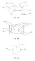
- FIG. 1A is a perspective view of a light reflecting shade according to a preferred embodiment of the present invention.
- FIG. 1B is a top view of FIG. 1A ;
- FIG. 1C is a side view of FIG. 1A ;
- FIG. 2A is a schematic diagram of optical paths of a light reflecting shade according to a prefered embodiment of the present invention.
- FIG. 2B is a distribution diagram of light angles of a light reflecting shade according to a prefered embodiment of the present invention.
- FIG. 3A is a top view of a light reflecting shade according to another preferred embodiment of the present invention.
- FIG. 3B is a side view from a shorter side of the rectangular light reflecting shade in FIG. 3A ;
- FIG. 3C is a side view from a longer side of the rectangular light reflecting shade in FIG. 3A ;
- FIG. 4A is an exploded view of an illuminant module according to a preferred embodiment of the present invention.
- FIG. 4B is a perspective view of the assembled illuminant module shown in FIG. 4A ;
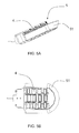
- FIGS. 5A and 5B are schematic diagrams of an illuminant device according to a preferred embodiment of the present invention.
- FIGS. 1A to 1C show a light reflecting shade according to a preferred embodiment of the present invention.
- FIG. 1B is a top view of FIG. 1A
- FIG. 1C is a side view of FIG. 1A .
- the light reflecting shade includes a plurality of reflecting sheets 10 assembled together to form a conoid-like structure 1, or a single reflecting sheet bent to form a conoid-like structure 1.
- the conoid-like structure 1 has a first portion 11, a second portion 12, a first side 13 and a corresponding second side 14.
- the first side 13 is an open side, and the light source is disposed at the first side.
- the first side 13 can also be a close end.
- the second side 14 is a light emitting side.
- the first portion 11 and the second portion 12 are stacked together to form the conoid-like structure 1.
- the first conoid-like prtion 11 and the second portion 12 are respectively include a plurality of reflecting planes 111, 121.
- the first side 13 and the second side 14 can be respectively an ellipse, a circle, a rectangle, a polygon or an irregular shape to meet the real requirement.
- the first side 13 and the second side 14 are parallel or unparallel.
- the slope of one reflecting plane 111 of the first portion 11 is different from that of corresponding reflecting plane 121 of the second portion 12.
- the conoid-like structure 1 is formed as a single piece by the first portion 11 and the second portion 12, or is formed by assembling the first portion 11 and the second portion 12 together.
- the central axis of the first side 13 can be aligned or not aligned with the central axis of the second side 14.
- each side of the conoid-like structure 1 includes two reflecting planes 111, 121 with various slopes so as to reflect more angles of light and concentrate the light in the specified area and angle as shown in FIG. 2A .
- the reflecting shade of the present invention can reduce the light-emitting angle and concentrate the light angle distribution as shown in FIG. 2B .
- the conoid-like structure can be formed by more than two portions as shown in FIG. 3A to 3C .
- the illuminant module 4 includes a light reflecting shade 41, a light source 42, a substrate 43, a heat sink 44, a housing 45, a transparent plate 451, a rubber pad 46, and a power connection line 47.
- the light reflecting shade 41 disposed corresponding to the light source 52 includes at least one reflecting sheet.
- Each light reflecting shade 41 has a first side and a second side.
- the light source 42 is disposed at the first side and the second side is a light emitting side.
- the light reflecting shade is a conoid-like structure formed by two or more portions with a plurality of reflecting planes, and the slope of one reflecting plane of one portion is different from that of corresponding reflecting plane of another portion.
- the light source 42 is disposed on the substrate 43, and the heat sink 44 is disposed under the substrate 43 for heat dissipation.
- the housing 45 connected to the heat sink 44 for covering the light source 42, the substrate 43 and light reflecting shade 41 is made of aluminum.
- a transparent plate 451 is disposed above the housing 45 for passing the light therethrough.
- a thermally conducting material can be attached to the surface of the substrate43.
- the light source 42 is a light emitting diode (LED) electrically connected to the power connection line 47.
- the rubber pad 46 is disposed between the housing 45 and the heat sink 44 for water-proof function.
- the light reflecting shade 41 is made of aluminum and a high reflective material on a surface thereof formed by plating or coating. Such high reflective material is preferably silver.
- the illuminant device includes an annular frame 51 and a plurality of illuminant modules 4 in FIG. 4B disposed on the annular frame.
- the plurality of illuminant modules 4 are arranged and assembled at the same plane or different planes.
- the illuminant modules 4 are arranged in an arc shape having a three-row structure.
- the illuminant modules 4 in the central row are arranged horizontally, and the other two rows lean toward the center in an angle and hence an arc shape is formed.
- the illuminant device 5 is preferably a street lamp, searchlight or projection lamp.
- the illuminant device and its light reflecting shade have a plurality of reflecting planes at the same side of the conoid-like structure. Therefore, the light reflecting shade can achieve high directivity and concentrate the light in the specified area and angle.
- the utilization efficiency of the light device can be enhanced by concentrating the light. With a uniform luminance, the light device enhances the utilization efficiency and reduces the undesired scattering light, hence decreasing the number of the light sources so as to lower the cost.
Landscapes
- Engineering & Computer Science (AREA)
- General Engineering & Computer Science (AREA)
- Physics & Mathematics (AREA)
- Microelectronics & Electronic Packaging (AREA)
- Optics & Photonics (AREA)
- Non-Portable Lighting Devices Or Systems Thereof (AREA)
- Arrangement Of Elements, Cooling, Sealing, Or The Like Of Lighting Devices (AREA)
Abstract
Description
- This Non-provisional application claims priority under under Art 87 EPC of Patent Application No.
097141113 - The present invention relates to an illuminant device and its light reflecting shade and, in particular, to a light reflecting shade having a high directivity and capable of concentrating the light in the specified area.
- The mercury lamp, high-pressure sodium (HPS) lamp, or metal halide lamp with a hemispheric light shade are commonly used as the conventional street lamp. The conventional light shade reflects the light from the back or from the side to the front through the spherical reflecting surface. Since the light shade merely reflects the light to the front without directivity, it cannot effectively concentrate the light in the specified area such that the utilization efficiency of the lamp is low and the undesired scattering light is produced. These will cause an influence on the drivers, pedestrians, and even surrounding building.
- The present invention is to provide an illuminant device and its light reflecting shade, particularly a light reflecting shade having a high directivity and capable of concentrating the light in the specified area.
- To achieve the above, a light reflecting shade according to the present invention is used to reflect the light emitted from a light source. Such light reflecting shade includes a plurality of reflecting sheets forming a conoid-like structure with a plurality of reflecting planes, a first side and a corresponding second side. The light source is disposed at the first side and the second side is a light emitting side.
- The first side is open or closed for disposing the reflecting sheet. The first side is parallel or unparallel with the second side. The area of the second side is greater than that of the first side, and the first side and the second side have respectively an ellipse, a circle, a rectangle, a polygon or an irregular profile. The material of the reflecting sheet is aluminum or metal. The surface of the reflecting sheet includes a high reflective material formed by plating or coating, and the high reflective material is preferably silver. The conoid-like structure is formed by bending the single reflecting sheet or assembling the plurality of reflecting sheets together.
- The reflecting planes are disposed inside the conoid-like structure formed by one or more portions, and the slope of one reflecting plane of one portion is different from that of corresponding reflecting plane of another portion. The conoid-like structure is formed as a single piece, or is formed by assembling the plurality of portions together. The central axis of the first side is aligned or not aligned with the central axis of the second side.
- To achieve the above, the illuminant device according to the present invention is arranged and assembled by at least one illuminant module. Each illuminant module includes at least one light source, at least one light reflecting shade, a substrate, and a heat sink. The light reflecting shade is disposed corresponding to the light source and includes at least one reflecting sheet to form a conoid-like structure. The conoid-like structure has a plurality of portions, a first side and a second side. Each portion comprises a plurality of reflecting planes. The light source is disposed at the first side and the second side is a light emitting side. The light source is disposed on the substrate and the heat sink is disposed under the substrate for heat dissipation.
- The light source is preferably a light emitting diode (LED). The illuminant module further includes a power connection line, a housing, and a rubber pad. The power connection line is electrically connected to the light source. The material of the housing is preferably aluminum, and the housing is connected to the heat sink for covering the light source, substrate, and light reflecting shade. The housing further includes a transparent plate, which is preferably made of glass and disposed above the light source for passing the light therethrough. The rubber pad is disposed between the housing and the heat sink for providing the water-proof function to the light source.
- The above-mentioned illuminant modules are arranged and assembled at the same plane or different planes, and are preferably assembled in an arc shape. The above-mentioned illuminant device further includes a frame for disposing the illuminant modules thereon. The illuminant device is preferably a street lamp, a searchlight or a projection lamp.
- The present invention will become more fully understood from the subsequent detailed description and accompanying drawings, which are given by way of illustration only, and thus are not limitative of the present invention, and wherein:
-
FIG. 1A is a perspective view of a light reflecting shade according to a preferred embodiment of the present invention; -
FIG. 1B is a top view ofFIG. 1A ; -
FIG. 1C is a side view ofFIG. 1A ; -
FIG. 2A is a schematic diagram of optical paths of a light reflecting shade according to a prefered embodiment of the present invention; -
FIG. 2B is a distribution diagram of light angles of a light reflecting shade according to a prefered embodiment of the present invention; -
FIG. 3A is a top view of a light reflecting shade according to another preferred embodiment of the present invention; -
FIG. 3B is a side view from a shorter side of the rectangular light reflecting shade inFIG. 3A ; -
FIG. 3C is a side view from a longer side of the rectangular light reflecting shade inFIG. 3A ; -
FIG. 4A is an exploded view of an illuminant module according to a preferred embodiment of the present invention; -
FIG. 4B is a perspective view of the assembled illuminant module shown inFIG. 4A ; and -
FIGS. 5A and 5B are schematic diagrams of an illuminant device according to a preferred embodiment of the present invention. - The present invention will be apparent from the following detailed description, which proceeds with reference to the accompanying drawings, wherein the same references relate to the same elements.
-
FIGS. 1A to 1C show a light reflecting shade according to a preferred embodiment of the present invention.FIG. 1B is a top view ofFIG. 1A and FIG. 1C is a side view ofFIG. 1A . The light reflecting shade includes a plurality of reflectingsheets 10 assembled together to form a conoid-like structure 1, or a single reflecting sheet bent to form a conoid-like structure 1. The conoid-like structure 1 has afirst portion 11, asecond portion 12, afirst side 13 and a correspondingsecond side 14. Thefirst side 13 is an open side, and the light source is disposed at the first side. Thefirst side 13 can also be a close end. Thesecond side 14 is a light emitting side. Thefirst portion 11 and thesecond portion 12 are stacked together to form the conoid-like structure 1. The first conoid-like prtion 11 and thesecond portion 12 are respectively include a plurality of reflectingplanes first side 13 and thesecond side 14 can be respectively an ellipse, a circle, a rectangle, a polygon or an irregular shape to meet the real requirement. Thefirst side 13 and thesecond side 14 are parallel or unparallel. - The slope of one reflecting
plane 111 of thefirst portion 11 is different from that of corresponding reflectingplane 121 of thesecond portion 12. The conoid-like structure 1 is formed as a single piece by thefirst portion 11 and thesecond portion 12, or is formed by assembling thefirst portion 11 and thesecond portion 12 together. The central axis of thefirst side 13 can be aligned or not aligned with the central axis of thesecond side 14. - Accordingly, each side of the conoid-
like structure 1 includes two reflectingplanes FIG. 2A . Otherwise, the reflecting shade of the present invention can reduce the light-emitting angle and concentrate the light angle distribution as shown inFIG. 2B . Certainly, the conoid-like structure can be formed by more than two portions as shown inFIG. 3A to 3C . - With reference to
FIGS. 4A and4B , theilluminant module 4 includes alight reflecting shade 41, alight source 42, asubstrate 43, aheat sink 44, ahousing 45, atransparent plate 451, arubber pad 46, and apower connection line 47. Thelight reflecting shade 41 disposed corresponding to the light source 52 includes at least one reflecting sheet. Eachlight reflecting shade 41 has a first side and a second side. Thelight source 42 is disposed at the first side and the second side is a light emitting side. The light reflecting shade is a conoid-like structure formed by two or more portions with a plurality of reflecting planes, and the slope of one reflecting plane of one portion is different from that of corresponding reflecting plane of another portion. Thelight source 42 is disposed on thesubstrate 43, and theheat sink 44 is disposed under thesubstrate 43 for heat dissipation. Thehousing 45 connected to theheat sink 44 for covering thelight source 42, thesubstrate 43 andlight reflecting shade 41 is made of aluminum. Atransparent plate 451 is disposed above thehousing 45 for passing the light therethrough. A thermally conducting material can be attached to the surface of the substrate43. - The
light source 42 is a light emitting diode (LED) electrically connected to thepower connection line 47. Therubber pad 46 is disposed between thehousing 45 and theheat sink 44 for water-proof function. Thelight reflecting shade 41 is made of aluminum and a high reflective material on a surface thereof formed by plating or coating. Such high reflective material is preferably silver. - With reference to
FIGS. 5A and 5B , the illuminant device includes anannular frame 51 and a plurality ofilluminant modules 4 inFIG. 4B disposed on the annular frame. The plurality ofilluminant modules 4 are arranged and assembled at the same plane or different planes. In one embodiment of the present invention, theilluminant modules 4 are arranged in an arc shape having a three-row structure. Theilluminant modules 4 in the central row are arranged horizontally, and the other two rows lean toward the center in an angle and hence an arc shape is formed. Theilluminant device 5 is preferably a street lamp, searchlight or projection lamp. - To sum up, the illuminant device and its light reflecting shade have a plurality of reflecting planes at the same side of the conoid-like structure. Therefore, the light reflecting shade can achieve high directivity and concentrate the light in the specified area and angle. The utilization efficiency of the light device can be enhanced by concentrating the light. With a uniform luminance, the light device enhances the utilization efficiency and reduces the undesired scattering light, hence decreasing the number of the light sources so as to lower the cost.
- Although the present invention has been described with reference to specific embodiments, this description is not meant to be construed in a limiting sense. Various modifications of the disclosed embodiments, as well as alternative embodiments, will be apparent to persons skilled in the art. It is, therefore, contemplated that the appended claims will cover all modifications that fall within the true scope of the present invention.
Claims (15)
- A light reflecting shade for reflecting a light emitted from a light source, comprising:at least one reflecting sheet forming a conoid-like structure, wherein the conoid-like structure comprises a plurality of portions with a plurality of reflecting planes, a first side and a second side, the light source is disposed at the first side, and the second side is a light emitting side.
- The light reflecting shade according to claim 1, wherein the first side or the second side has an ellipse, trapezoid, circle, rectangle, polygon or irregular profile, and the first side is open or closed.
- The light reflecting shade according to claim 1 or 2, wherein the area of the second side is greater than that of the first side, and the first side and the second side are parallel or unparallel.
- The light reflecting shade according to one of the claims 1 to 3, wherein the reflecting sheet is made of aluminum or metal and has a high reflective material formed by plating or coating on a surface thereof.
- The light reflecting shade according to one of the claims 1 to 4, wherein the conoid-like structure is formed by bending the single reflecting sheet or assembling the plurality of reflecting sheets together.
- The light reflecting shade according to one of the claims 1 to 5, wherein the reflecting planes are disposed inside the conoid-like structure.
- The light reflecting shade according to one of the claims 1 to 6, wherein the slope of one reflecting plane of one portion is different from that of corresponding reflecting plane of another portion.
- The light reflecting shade according to one of the claims 1 to7, wherein the conoid-like structure is formed as a single piece, or is formed by assembling the plurality of portions together.
- The light reflecting shade according to one of the claims 1 to 8, wherein the central axis of the first side is aligned or not aligned with the central axis of the second side.
- An illuminant device assembled by at least one illuminant module, the illuminant module comprising:at least one light source;at least one light reflecting shade disposed corresponding to the light source and comprising at least one reflecting sheet to form a conoid-like structure, wherein the conoid-like structure comprises a plurality of portions with a plurality of reflecting planes, a first side and a second side, the light source is disposed at the first side, and the second side is a light emitting side; anda substrate for disposing the light source thereon.
- The illuminant device according to claim 10, wherein the illuminant module further comprises a housing for covering the light source, the substrate and the light reflecting shade, and in particular wherein the housing further comprises a transparent plate disposed on an optical path of the light source for passing the light therethrough, and in particular wherein the material of the housing is aluminum, and the material of the transparent plate is glass.
- The illuminant device according to claim 10 or 11, wherein the illuminant module further comprises a heat sink disposed at one side of the substrate for dissipating heat of the light source, and in particular wherein the illuminant module further comprises a rubber pad disposed between the housing and the heat sink for providing a water-proof function.
- The illuminant device according to one of the claims 10 to 12, wherein the plurality of illuminant modules are arranged and assembled at the same plane, different planes or in arc shape.
- The illuminant device according to one of the claims 10 to 13, further comprising a frame for disposing the plurality of illuminant modules thereon.
- The illuminant device according to one of the claims 10 to 14, wherein the illuminant device is a street lamp, a searchlight or a projection lamp, and/or wherein the light source is a light emitting diode (LED), and the illuminant module comprises a power connection line electrically connected to the light source, and/or wherein a heat conducting material is attached to the surface of the substrate.
Applications Claiming Priority (1)
| Application Number | Priority Date | Filing Date | Title |
|---|---|---|---|
| TW097141113A TW201017052A (en) | 2008-10-27 | 2008-10-27 | Illuminant device and light reflecting shade thereof |
Publications (1)
| Publication Number | Publication Date |
|---|---|
| EP2180244A1 true EP2180244A1 (en) | 2010-04-28 |
Family
ID=40616430
Family Applications (1)
| Application Number | Title | Priority Date | Filing Date |
|---|---|---|---|
| EP08173055A Withdrawn EP2180244A1 (en) | 2008-10-27 | 2008-12-30 | Illuminant device and light reflecting shade thereof |
Country Status (3)
| Country | Link |
|---|---|
| US (1) | US20100103670A1 (en) |
| EP (1) | EP2180244A1 (en) |
| TW (1) | TW201017052A (en) |
Cited By (1)
| Publication number | Priority date | Publication date | Assignee | Title |
|---|---|---|---|---|
| ITRM20130677A1 (en) * | 2013-12-09 | 2015-06-10 | Alba Tek 2013 | OPTICAL GROUP |
Families Citing this family (7)
| Publication number | Priority date | Publication date | Assignee | Title |
|---|---|---|---|---|
| JP5716156B2 (en) * | 2011-03-31 | 2015-05-13 | 株式会社オプトデザイン | Linear light source device using point light source and illumination device for optical reader using the same |
| USD682458S1 (en) * | 2012-07-21 | 2013-05-14 | Nathan Howard Calvin | Lighting fixture |
| ITMI20130509A1 (en) * | 2013-04-04 | 2014-10-05 | Bevilacqua Carlotta Francesca Isolina Maria De | LIGHTING SYSTEM WITH OPTICAL MODULAR ASYMMETRICAL ELEMENTS |
| DE102013207609A1 (en) * | 2013-04-25 | 2014-10-30 | Osram Gmbh | Reflector arrangement with multiple reflectors and semiconductor light sources |
| JP6470030B2 (en) * | 2014-12-16 | 2019-02-13 | 株式会社エンプラス | Reflective member, illumination device, surface light source device, display device, and electronic apparatus |
| JP6906968B2 (en) * | 2017-01-31 | 2021-07-21 | 株式会社ジャパンディスプレイ | Lighting device |
| CN119572993B (en) * | 2025-01-15 | 2025-11-11 | 江苏跃马建工集团有限公司 | Energy-saving street lamp shade |
Citations (4)
| Publication number | Priority date | Publication date | Assignee | Title |
|---|---|---|---|---|
| US20030165061A1 (en) * | 2002-03-01 | 2003-09-04 | Martineau Patrick M. | Light emitting diode reflector |
| US20050128744A1 (en) * | 2003-12-11 | 2005-06-16 | Dialight Corporation | High flux light emitting diode (LED) reflector arrays |
| EP1586814A2 (en) * | 2004-04-16 | 2005-10-19 | TRILUX-LENZE GmbH + Co. KG | Lighting system |
| WO2007104136A1 (en) * | 2006-03-13 | 2007-09-20 | Tir Technology Lp | Optical device for mixing and redirecting light |
Family Cites Families (7)
| Publication number | Priority date | Publication date | Assignee | Title |
|---|---|---|---|---|
| US4153929A (en) * | 1976-10-20 | 1979-05-08 | Meddev Corporation | Light assembly |
| US4261030A (en) * | 1979-03-15 | 1981-04-07 | Esquire, Inc. | Wrap-around parabolic light fixture and method for manufacture |
| US4504888A (en) * | 1983-03-23 | 1985-03-12 | Pennywise Enterprises, Inc. | Photographer's diffuser light |
| US5047900A (en) * | 1991-01-07 | 1991-09-10 | Eastman Kodak Company | Electronic flash apparatus |
| US6733145B2 (en) * | 2000-08-29 | 2004-05-11 | John E. Shirilla | Folding softbox |
| US6585398B1 (en) * | 2001-06-22 | 2003-07-01 | Genlyte Thomas Group, Llc | Post top deck light fixture |
| US7470044B2 (en) * | 2006-03-22 | 2008-12-30 | The Picture People | Light diffusion device |
-
2008
- 2008-10-27 TW TW097141113A patent/TW201017052A/en unknown
- 2008-12-29 US US12/345,122 patent/US20100103670A1/en not_active Abandoned
- 2008-12-30 EP EP08173055A patent/EP2180244A1/en not_active Withdrawn
Patent Citations (4)
| Publication number | Priority date | Publication date | Assignee | Title |
|---|---|---|---|---|
| US20030165061A1 (en) * | 2002-03-01 | 2003-09-04 | Martineau Patrick M. | Light emitting diode reflector |
| US20050128744A1 (en) * | 2003-12-11 | 2005-06-16 | Dialight Corporation | High flux light emitting diode (LED) reflector arrays |
| EP1586814A2 (en) * | 2004-04-16 | 2005-10-19 | TRILUX-LENZE GmbH + Co. KG | Lighting system |
| WO2007104136A1 (en) * | 2006-03-13 | 2007-09-20 | Tir Technology Lp | Optical device for mixing and redirecting light |
Cited By (1)
| Publication number | Priority date | Publication date | Assignee | Title |
|---|---|---|---|---|
| ITRM20130677A1 (en) * | 2013-12-09 | 2015-06-10 | Alba Tek 2013 | OPTICAL GROUP |
Also Published As
| Publication number | Publication date |
|---|---|
| TW201017052A (en) | 2010-05-01 |
| US20100103670A1 (en) | 2010-04-29 |
Similar Documents
| Publication | Publication Date | Title |
|---|---|---|
| EP2175194A1 (en) | Illuminant device and light reflecting shade thereof | |
| CN102654252B (en) | Lens and illumination device | |
| US20100103670A1 (en) | Illuminant device and light reflecting shade thereof | |
| EP1697685B1 (en) | High flux light emitting diode (led) reflector arrays | |
| US8251546B2 (en) | LED lamp with a plurality of reflectors | |
| US20110170299A1 (en) | Led light bulb | |
| US8814384B2 (en) | Light having LED modules | |
| CN101725903A (en) | Lighting device and light reflector thereof | |
| CN202647231U (en) | Light-emitting device and illumination apparatus | |
| CN101718415B (en) | Lighting device and light reflector thereof | |
| KR101086017B1 (en) | Panel LED Lighting | |
| CN102239362A (en) | Lighting device | |
| TWI603029B (en) | Light emitting module | |
| JP2015088389A (en) | Lighting device | |
| KR101723164B1 (en) | Led luminaire | |
| US9328911B2 (en) | LED lamp with a heat dissipation structure capable of omnidirectionally emitting light | |
| JP6094618B2 (en) | lamp | |
| JP3189005U (en) | Light emitting diode holder and its lamp | |
| US20140003087A1 (en) | LED Panel Lighting Device | |
| JP5636790B2 (en) | Lighting device | |
| KR101049831B1 (en) | LED lighting device | |
| JP5383758B2 (en) | Lighting device | |
| KR101633334B1 (en) | Lighting device using LED | |
| JP2012204211A (en) | Lighting fixture | |
| JP6187527B2 (en) | lamp |
Legal Events
| Date | Code | Title | Description |
|---|---|---|---|
| PUAI | Public reference made under article 153(3) epc to a published international application that has entered the european phase |
Free format text: ORIGINAL CODE: 0009012 |
|
| 17P | Request for examination filed |
Effective date: 20100105 |
|
| AK | Designated contracting states |
Kind code of ref document: A1 Designated state(s): AT BE BG CH CY CZ DE DK EE ES FI FR GB GR HR HU IE IS IT LI LT LU LV MC MT NL NO PL PT RO SE SI SK TR |
|
| AX | Request for extension of the european patent |
Extension state: AL BA MK RS |
|
| AKX | Designation fees paid |
Designated state(s): AT BE BG CH CY CZ DE DK EE ES FI FR GB GR HR HU IE IS IT LI LT LU LV MC MT NL NO PL PT RO SE SI SK TR |
|
| STAA | Information on the status of an ep patent application or granted ep patent |
Free format text: STATUS: THE APPLICATION IS DEEMED TO BE WITHDRAWN |
|
| 18D | Application deemed to be withdrawn |
Effective date: 20130702 |