EP2180130B1 - Fire door comprising a steel frame and adhesively attached panels - Google Patents
Fire door comprising a steel frame and adhesively attached panels Download PDFInfo
- Publication number
- EP2180130B1 EP2180130B1 EP20080167372 EP08167372A EP2180130B1 EP 2180130 B1 EP2180130 B1 EP 2180130B1 EP 20080167372 EP20080167372 EP 20080167372 EP 08167372 A EP08167372 A EP 08167372A EP 2180130 B1 EP2180130 B1 EP 2180130B1
- Authority
- EP
- European Patent Office
- Prior art keywords
- door
- door frame
- bonding agent
- door panel
- screw
- Prior art date
- Legal status (The legal status is an assumption and is not a legal conclusion. Google has not performed a legal analysis and makes no representation as to the accuracy of the status listed.)
- Not-in-force
Links
Images

Classifications
-
- E—FIXED CONSTRUCTIONS
- E06—DOORS, WINDOWS, SHUTTERS, OR ROLLER BLINDS IN GENERAL; LADDERS
- E06B—FIXED OR MOVABLE CLOSURES FOR OPENINGS IN BUILDINGS, VEHICLES, FENCES OR LIKE ENCLOSURES IN GENERAL, e.g. DOORS, WINDOWS, BLINDS, GATES
- E06B3/00—Window sashes, door leaves, or like elements for closing wall or like openings; Layout of fixed or moving closures, e.g. windows in wall or like openings; Features of rigidly-mounted outer frames relating to the mounting of wing frames
- E06B3/70—Door leaves
- E06B3/72—Door leaves consisting of frame and panels, e.g. of raised panel type
- E06B3/725—Door leaves consisting of frame and panels, e.g. of raised panel type with separate hollow frames, e.g. foam-filled
- E06B3/726—Door leaves consisting of frame and panels, e.g. of raised panel type with separate hollow frames, e.g. foam-filled of metal
-
- E—FIXED CONSTRUCTIONS
- E06—DOORS, WINDOWS, SHUTTERS, OR ROLLER BLINDS IN GENERAL; LADDERS
- E06B—FIXED OR MOVABLE CLOSURES FOR OPENINGS IN BUILDINGS, VEHICLES, FENCES OR LIKE ENCLOSURES IN GENERAL, e.g. DOORS, WINDOWS, BLINDS, GATES
- E06B5/00—Doors, windows, or like closures for special purposes; Border constructions therefor
- E06B5/10—Doors, windows, or like closures for special purposes; Border constructions therefor for protection against air-raid or other war-like action; for other protective purposes
- E06B5/16—Fireproof doors or similar closures; Adaptations of fixed constructions therefor
-
- E—FIXED CONSTRUCTIONS
- E06—DOORS, WINDOWS, SHUTTERS, OR ROLLER BLINDS IN GENERAL; LADDERS
- E06B—FIXED OR MOVABLE CLOSURES FOR OPENINGS IN BUILDINGS, VEHICLES, FENCES OR LIKE ENCLOSURES IN GENERAL, e.g. DOORS, WINDOWS, BLINDS, GATES
- E06B3/00—Window sashes, door leaves, or like elements for closing wall or like openings; Layout of fixed or moving closures, e.g. windows in wall or like openings; Features of rigidly-mounted outer frames relating to the mounting of wing frames
- E06B3/70—Door leaves
- E06B3/7015—Door leaves characterised by the filling between two external panels
- E06B2003/7042—Door leaves characterised by the filling between two external panels with a fire retardant layer
-
- E—FIXED CONSTRUCTIONS
- E06—DOORS, WINDOWS, SHUTTERS, OR ROLLER BLINDS IN GENERAL; LADDERS
- E06B—FIXED OR MOVABLE CLOSURES FOR OPENINGS IN BUILDINGS, VEHICLES, FENCES OR LIKE ENCLOSURES IN GENERAL, e.g. DOORS, WINDOWS, BLINDS, GATES
- E06B3/00—Window sashes, door leaves, or like elements for closing wall or like openings; Layout of fixed or moving closures, e.g. windows in wall or like openings; Features of rigidly-mounted outer frames relating to the mounting of wing frames
- E06B3/70—Door leaves
- E06B2003/7059—Specific frame characteristics
- E06B2003/7074—Metal frames
Definitions
- the invention relates to a steel-structured door, which comprises a door frame of steel, a refractory heat insulation, and a door panel on each face of the door, making up an external side of the door.
- the invention relates also to a method of manufacturing a steel-structured door, which method comprises attaching to a door frame of steel on each side a door panel as a face for making up an external side of the door.
- Steel-structured doors are typically used in projects, wherein the door is used for establishing a compartment stopping or retarding the spreading of fire in a building.
- Such typical projects include, among others, doors between stairwells used as emergency exit routes in shopping malls and office buildings and the rest of the business premises or other premises, doors between parking facilities and exit routes, and so on.
- the rate of using a door can often be remarkably high, the door being thus subjected to numerous loading times throughout the day.
- EP 1 207 239 A2 which deals with fireproof panels.
- the structure described in the cited publication includes a metal layer, adhesion means, a fire-resistant foam, a mechanical bonding element with adhesion means, and a fire-resistant foam with mechanical bonding elements.
- US 6389769 patent describes a method of manufacturing a steel-structured door by attaching to a door frame of steel on each side a door panel as a face for making up an external side of the door.
- the door panel is attached to the door frame by the application of an adhesive.
- US 2005/0144871 describes a door and a method for assembling a door.
- the door is assembled by placing internal frame components on a surface and securing an interior sheath to the internal frame components, and then securing an exterior sheath to the internal frame components.
- the interior sheath and exterior sheath are secured to the frame by adhesive or other structural fastening methods.
- WO 8604108 describes a security door, which comprises a sheet of aluminium and a sheet profile frame of steel.
- the steel frame is fastened to the strips welded to the rear face of aluminium sheet by means of mechanical joining agent, e.g. bolts.
- the type approval refers to: A section in the Finnish building code, entitled Doors, a Ministry of the Environment statute of October 22, 2007 regarding type approval of doors, the EI class fire door of metal.
- Another objective of the invention is to provide a steel-structured door, which fulfils the quality criteria set therefor, regarding, among other things, straightness, appearance, finish, and durability, the door being still economically viable to manufacture and simple in terms of manufacturing technology, whereby the door structure makes its own contribution towards minimizing possible quality discrepancies in production.
- a still further objective is to provide a steel-structured door, which is as resistant as possible to vandalism and other possible unconventional use.
- a yet further objective in a method according to the invention is to provide a straightforward, simple, and economically attractive way of manufacturing a steel-structured door.
- An objective according to one feature of the method is to provide such a door assembly process, by means of which the appearance changes of a door can be maintained at a minimum, i.e. the manufacturing-related stresses applied to the door panel do not result in a change of the door appearance.
- this process step enables providing a fire-resistance upgrading structural detail regarding the construction of a door. This constitutes an objective, especially in cases where the exterior of a steel-structured door consists of stainless steel, which is not actually further coated, painted or similarly surface-treated in the finishing process.
- a steel-structured door has been attached to the door frame by means of a bonding agent, which is applied as an undulating, such as a sine-wave shaped, continuous extrudate by means of a die onto the door frame or the door panel.
- a bonding agent which is applied as an undulating, such as a sine-wave shaped, continuous extrudate by means of a die onto the door frame or the door panel.
- the door panel is attached to the door frame by the application of a bonding agent), which is applied as an undulating, such as a sine-wave shaped, continuous extrudate by means of a die onto the door frame or the door panel.
- a bonding agent which is applied as an undulating, such as a sine-wave shaped, continuous extrudate by means of a die onto the door frame or the door panel.
- the X-direction corresponds to a lengthwise dimension of the structure, which is hence for example the vertical direction of a door.
- the Y-direction corresponds to a lateral dimension of the door opening. Consequently, the XY-plane is essentially the same as the direction of the door plane.
- the Z-direction is a thickness or depth dimension. As this invention is particularly concerned with thermal engineering features of the structural elements, the Z-direction is generally also consistent with the direction of an installed structure's temperature gradient in a fire situation.
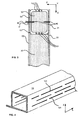
- FIG. 1 illustrates a door structure in a general view.
- a steel-structured door 1 of the invention comprises a door frame 10 of steel, a fireproof heat insulation 30, and a door panel 20 on each face of the door 1, making up a façade for the door and said door panel 20 being fixed to the door frame 10 by means of a bonding agent 50.
- Fig. 2 illustrates one cross-section of a steel-structured door in Z-direction.
- the bonding agent 50 represents such a material which is capable of forming an adhesion-based joint between the door panel 20 and the door frame 10.
- the bonding agent 50 includes plastics as its basic ingredient, thus providing a sufficient toughness and elasticity for the joint. Toughness, elasticity, and impact resistance are particularly desirable qualities for normal use of the door. The users often apply substantial forces to the door, especially if an optional door-mounted damper is out of order. The attachment of a door panel to a door frame must not start to crack or delaminate. On the other hand, there are no prior known proposals for providing a fire resistance, which is sufficient for obtaining a type approval for a door and which is implemented by means of a plastic-based adhesive bonding agent.
- the bonding agent is applied as an undulating, such as a sine-wave shaped, continuous extrudate by means of a die onto the door frame or the door panel.
- the elements to be connected to each other are placed precisely in a correct position and said elements are pressed together.
- a suitable amount and application geometry of bonding agent provide a sought-after final result.
- the undulating continuous extrudate or ribbon of a bonding agent turns into a flat film, which retains the door panel securely in place and seals the joint hermetically.
- the extrudate turns into a relatively consistent film as a result of flattening, whereby the number of air pockets or non-adhered spots can be minimized.
- the sine-wave form is particularly beneficial as the air is able to discharge thoroughly from the joint and the wave form is mathematically simple to calculate, which in turn facilitates an automated application of the proper amount.
- the film thickness bears an effect not only on the strength alone of a steel-structured door in normal use but also in a possible extreme situation, i.e. when fire resistance is called for.
- the bonding agent admittedly becomes charred and turns brittle, yet is still able to hold the door panel fixed to the door frame.
- it will lose its adhesiveness too quickly and, on the other hand, if there is too much bonding agent, it does not work as desired.
- the film thickness in a finished door is preferably within the range of 0,1-1 mm, more preferably 200-500 pm, the optimal end result shall be attained.
- the door frame 10 can be optionally constructed in a steel profile, wherein the propagation of heat in the Z-direction of a door is retarded by means of heat discontinuities 101.
- a highly appropriate heat discontinuity profile has been described in the same Patent Applicant's earlier utility model, application number FI-U 20060166 (the same patent family includes also DE-UM 202007005298.7 ).
- a refractory heat insulation inside the door can be preferably provided by using for example a highly appropriate fire protection insulation, such as mineral wool-based PAROC FPS 14, ISOVER PKOL or the like.
- the door manufacturing process comprises performing the following steps of:
- the first door panel 20 is placed on a working tool, a worktable or the like, the bonding agent 50 is applied to the door panel 20 in spots against which the door frame 10 settles, the door frame 10 is installed, the insulations 30 are installed, the bonding agent 50 is applied on the door frame 10, the second door panel 20 is placed on top of the door frame 10.
- This sequence may be slightly quicker than the above-described assembly sequence which requires a turnover of the frame but, on the other hand, it is slightly more difficult in this process to set the elements in precise alignment with each other by first attempt.
- One way of constructing a door frame 10 is, for example, such that elements like frame profiles, which make up the door frame 10, are assembled in a ring configuration and joined together, for example by welding X- and Y-directed frame profiles to each other.
- the door frame 10 can be constructed in the previously described step of the same process or can be acquired for example from a subcontractor.
- the attachment of the door panel 20 to the door frame 10 is backed up mechanically at least along an upper edge of the door panel 20. Further, according to a preferred embodiment, the mechanical backup is provided by way of screws 40.
- the upper edge of a door refers to such a region of the door which, when the door has been assembled and installed in its working position, lies in the X-direction (vertical direction) within a top quarter of the door panel 20. Preferably, this upper edge is a zone even narrower than the quarter area, but the precise structure is determined according to the construction of a door frame 10.
- the screws 40 can be left with their heads 42 exposed.
- a more preferred embodiment is such that the screws 40 for mechanical backup are made headless.
- This provides several benefits from the standpoint of a final result.
- the appearance of doors is almost without exception to provide information about the intended use thereof and to convey a certain image or impression about this particular location.
- the neatness and intactness of a door appearance are desirable qualities.
- the structures assembled by robust riveting, welding or by means of screws do not necessarily provide a desired final result, despite being potentially highly functional in technical sense. Welded structures, especially, are problematic as described earlier.
- the method further comprises steps, in which the screw 40 is left protrusive in the screwing process, such that between the screw's head 42 and the door panel's 20 surface 21 is visible some of the screw's threaded portion 41 (as shown in fig. 3 to the left of the door frame 10), after which the screw 40 is cut off to the flushness with or along the plane of the door panel's 20 surface 21 (as shown in fig. 3 to the right of the door frame 10).
- the screw 40 is left protrusive in the screwing process, such that between the screw's head 42 and the door panel's 20 surface 21 is visible some of the screw's threaded portion 41 (as shown in fig. 3 to the left of the door frame 10), after which the screw 40 is cut off to the flushness with or along the plane of the door panel's 20 surface 21 (as shown in fig. 3 to the right of the door frame 10).
- the presently described invention is applicable to projects other than those intended for fire door service.
- this option does not pass a fire test, which is specified in standard SFS-EN 1634-1 which was mentioned above when describing the objective of the claimed subject-matter.
- the melting point of aluminum is about 660°C (as compared to 1535° in steel)
- T the average temperature [°C]
- t time [min].
Description
- The invention relates to a steel-structured door, which comprises a door frame of steel, a refractory heat insulation, and a door panel on each face of the door, making up an external side of the door.
- The invention relates also to a method of manufacturing a steel-structured door, which method comprises attaching to a door frame of steel on each side a door panel as a face for making up an external side of the door.
- Steel-structured doors are typically used in projects, wherein the door is used for establishing a compartment stopping or retarding the spreading of fire in a building. Such typical projects include, among others, doors between stairwells used as emergency exit routes in shopping malls and office buildings and the rest of the business premises or other premises, doors between parking facilities and exit routes, and so on. Especially in public spaces, the rate of using a door can often be remarkably high, the door being thus subjected to numerous loading times throughout the day.
- Known from the prior art is, among others,
EP 1 207 239 A2 -
US 6389769 patent describes a method of manufacturing a steel-structured door by attaching to a door frame of steel on each side a door panel as a face for making up an external side of the door. The door panel is attached to the door frame by the application of an adhesive. -
US 2005/0144871 describes a door and a method for assembling a door. The door is assembled by placing internal frame components on a surface and securing an interior sheath to the internal frame components, and then securing an exterior sheath to the internal frame components. The interior sheath and exterior sheath are secured to the frame by adhesive or other structural fastening methods. -
WO 8604108 - One traditional way of manufacturing steel-structured doors, which doors match the official regulations regarding fire doors, is to construct the door from steel plate by bending and by welding the components to each other. Such doors require major investments in production, especially in terms of bending machines. Generally, the model of doors apt for such manufacturing process is relatively constant even in various sizes, so the question is about a large-scale bulk product manufacturing process. Another relevant aspect is the development of heat associated with welding. Particularly the door panel or face surface of a stainless-steel constructed door, constituting a façade of the door, makes a comparatively challenging welding project. This is because stainless steel has propensity to reshaping in response to the evolution of heat, perhaps even more propensity than other steel grades. Localized thermal expansion causes convexity, buckling incidents, and the like, which do not necessarily return to the original straight and flat surface. The welding-inflicted discoloration of material is not desirable, either. It is true that these discolorations can be dispelled later with appropriate chemical treatments, but that means more working processes and manufacturing costs.
- It is an objective of the invention to provide a steel-structured door capable of withstanding continuous use in public spaces, which door, when tested according to SFS-EN 1634-1 (confirmed on 2000-06-30), fulfils the qualifications required of a fire door for type approval. The type approval refers to: A section in the Finnish building code, entitled Doors, a Ministry of the Environment statute of October 22, 2007 regarding type approval of doors, the EI class fire door of metal. Another objective of the invention is to provide a steel-structured door, which fulfils the quality criteria set therefor, regarding, among other things, straightness, appearance, finish, and durability, the door being still economically viable to manufacture and simple in terms of manufacturing technology, whereby the door structure makes its own contribution towards minimizing possible quality discrepancies in production. A still further objective is to provide a steel-structured door, which is as resistant as possible to vandalism and other possible unconventional use.
- A yet further objective in a method according to the invention is to provide a straightforward, simple, and economically attractive way of manufacturing a steel-structured door. An objective according to one feature of the method is to provide such a door assembly process, by means of which the appearance changes of a door can be maintained at a minimum, i.e. the manufacturing-related stresses applied to the door panel do not result in a change of the door appearance. At the same time, this process step enables providing a fire-resistance upgrading structural detail regarding the construction of a door. This constitutes an objective, especially in cases where the exterior of a steel-structured door consists of stainless steel, which is not actually further coated, painted or similarly surface-treated in the finishing process.
- What is characteristic of a steel-structured door according to the invention is that the door panel has been attached to the door frame by means of a bonding agent, which is applied as an undulating, such as a sine-wave shaped, continuous extrudate by means of a die onto the door frame or the door panel.
- What is characteristic of a method according to the invention is that the door panel is attached to the door frame by the application of a bonding agent), which is applied as an undulating, such as a sine-wave shaped, continuous extrudate by means of a die onto the door frame or the door panel.
- In the context of this invention, directions used in reference to the structure are as follows. The X-direction corresponds to a lengthwise dimension of the structure, which is hence for example the vertical direction of a door. The Y-direction corresponds to a lateral dimension of the door opening. Consequently, the XY-plane is essentially the same as the direction of the door plane. The Z-direction is a thickness or depth dimension. As this invention is particularly concerned with thermal engineering features of the structural elements, the Z-direction is generally also consistent with the direction of an installed structure's temperature gradient in a fire situation.
- The invention will now be described in more detail with reference to the accompanying figures, in which figures:
-
fig. 1 shows a general view of a door structure, -
fig. 2 shows one cross-section of a door in Z-direction, -
fig. 3 shows one arrangement for ensuring the attachment of a door panel, -
fig. 4 shows one preferred profile for a door frame. -
Fig. 1 illustrates a door structure in a general view. A steel-structureddoor 1 of the invention comprises adoor frame 10 of steel, afireproof heat insulation 30, and adoor panel 20 on each face of thedoor 1, making up a façade for the door and saiddoor panel 20 being fixed to thedoor frame 10 by means of abonding agent 50. -
Fig. 2 illustrates one cross-section of a steel-structured door in Z-direction. - In the context of this invention, the
bonding agent 50 represents such a material which is capable of forming an adhesion-based joint between thedoor panel 20 and thedoor frame 10. Thebonding agent 50 includes plastics as its basic ingredient, thus providing a sufficient toughness and elasticity for the joint. Toughness, elasticity, and impact resistance are particularly desirable qualities for normal use of the door. The users often apply substantial forces to the door, especially if an optional door-mounted damper is out of order. The attachment of a door panel to a door frame must not start to crack or delaminate. On the other hand, there are no prior known proposals for providing a fire resistance, which is sufficient for obtaining a type approval for a door and which is implemented by means of a plastic-based adhesive bonding agent. Of course, such an extremely heat-resistant, plastic-based, adhesive bonding agent could be found for example in the attachments of ceramic tiles used in space shuttles or the like, but its price does not make economic sense in terms of manufacturing doors. In the context of this invention, it is an explicit objective to provide a structure which is economically as attractive as possible, yet fulfils the demands. Extensive studies associated with the invention have indicated that several polyurethane-based elastic bonding agents, such as glues or adhesive pastes, fulfill the demands set therefor both in terms of their technical features and price. - In one preferred embodiment of a method according to the invention, the bonding agent is applied as an undulating, such as a sine-wave shaped, continuous extrudate by means of a die onto the door frame or the door panel. After this, the elements to be connected to each other are placed precisely in a correct position and said elements are pressed together. A suitable amount and application geometry of bonding agent provide a sought-after final result. As a result of the compression, the undulating continuous extrudate or ribbon of a bonding agent turns into a flat film, which retains the door panel securely in place and seals the joint hermetically. By virtue of its undulating shape, the extrudate turns into a relatively consistent film as a result of flattening, whereby the number of air pockets or non-adhered spots can be minimized. About these undulating shapes, it should be noted that the sine-wave form is particularly beneficial as the air is able to discharge thoroughly from the joint and the wave form is mathematically simple to calculate, which in turn facilitates an automated application of the proper amount.
- It has also been discovered that the film thickness bears an effect not only on the strength alone of a steel-structured door in normal use but also in a possible extreme situation, i.e. when fire resistance is called for. With a correct film thickness, the bonding agent admittedly becomes charred and turns brittle, yet is still able to hold the door panel fixed to the door frame. In the event of having too little bonding agent, it will lose its adhesiveness too quickly and, on the other hand, if there is too much bonding agent, it does not work as desired. Based on the studies, when the film thickness in a finished door is preferably within the range of 0,1-1 mm, more preferably 200-500 pm, the optimal end result shall be attained.
- Furthermore, it can be noted from
fig. 2 that thedoor frame 10 can be optionally constructed in a steel profile, wherein the propagation of heat in the Z-direction of a door is retarded by means ofheat discontinuities 101. Such a highly appropriate heat discontinuity profile has been described in the same Patent Applicant's earlier utility model, application numberFI-U 20060166 DE-UM 202007005298.7 fig. 4 ), the transfer route of heat by conduction in the Z-direction has been disrupted, whereby the heat transferring by conduction is forced to travel a considerably longer distance in the X- or Y-direction for making it able to transfer in the Z-direction. Consequently, the heat spreading within the structure is not capable of crossing quickly from one side to the other. A refractory heat insulation inside the door can be preferably provided by using for example a highly appropriate fire protection insulation, such as mineral wool-based PAROC FPS 14, ISOVER PKOL or the like. - According to one method-related embodiment, the door manufacturing process comprises performing the following steps of:
- preparing the
door frame 10 for the application of abonding agent 50 - applying the
bonding agent 50 on a first side of thedoor frame 10 for attaching afirst door panel 20, - installing the
first door panel 20 correctly against thedoor frame 10 and pressing it in place for ensuring adherence of thebonding agent 50, - installing a
thermal insulation 30, - applying the
bonding agent 50 on a second side of thedoor frame 10 for attaching asecond door panel 20, - installing the
second door panel 20 correctly against thedoor frame 10 and pressing it in place for ensuring adherence of abonding agent 50. Thedoor frame 10 preparation process may include various process steps, such as, for example, fixing thedoor frame 10 to a working tool, cleaning the surfaces, applying, heating or other handling a possible primer. - As an alternative to the presented frame-based assembly mode, it is possible to employ a manufacturing process based on stacking sequence, wherein the door is assembled by stacking directly in the final order. Thus, the
first door panel 20 is placed on a working tool, a worktable or the like, thebonding agent 50 is applied to thedoor panel 20 in spots against which thedoor frame 10 settles, thedoor frame 10 is installed, theinsulations 30 are installed, thebonding agent 50 is applied on thedoor frame 10, thesecond door panel 20 is placed on top of thedoor frame 10. This sequence may be slightly quicker than the above-described assembly sequence which requires a turnover of the frame but, on the other hand, it is slightly more difficult in this process to set the elements in precise alignment with each other by first attempt. - One way of constructing a
door frame 10 is, for example, such that elements like frame profiles, which make up thedoor frame 10, are assembled in a ring configuration and joined together, for example by welding X- and Y-directed frame profiles to each other. Thedoor frame 10 can be constructed in the previously described step of the same process or can be acquired for example from a subcontractor. - Depicted in
fig. 3 are a few preferred features of the invention. In a steel-structured door, the attachment of thedoor panel 20 to thedoor frame 10 is backed up mechanically at least along an upper edge of thedoor panel 20. Further, according to a preferred embodiment, the mechanical backup is provided by way ofscrews 40. In the context of this invention, the upper edge of a door refers to such a region of the door which, when the door has been assembled and installed in its working position, lies in the X-direction (vertical direction) within a top quarter of thedoor panel 20. Preferably, this upper edge is a zone even narrower than the quarter area, but the precise structure is determined according to the construction of adoor frame 10. - In certain applications, the
screws 40 can be left with theirheads 42 exposed. However, according to one further developed embodiment, from the standpoint of the appearance and technical functionality of a door, a more preferred embodiment is such that thescrews 40 for mechanical backup are made headless. This provides several benefits from the standpoint of a final result. In public spaces, the appearance of doors is almost without exception to provide information about the intended use thereof and to convey a certain image or impression about this particular location. Thus, the neatness and intactness of a door appearance are desirable qualities. In such spaces, the structures assembled by robust riveting, welding or by means of screws do not necessarily provide a desired final result, despite being potentially highly functional in technical sense. Welded structures, especially, are problematic as described earlier. According to one preferred embodiment of the invention, the method further comprises steps, in which thescrew 40 is left protrusive in the screwing process, such that between the screw'shead 42 and the door panel's 20surface 21 is visible some of the screw's threaded portion 41 (as shown infig. 3 to the left of the door frame 10), after which thescrew 40 is cut off to the flushness with or along the plane of the door panel's 20 surface 21 (as shown infig. 3 to the right of the door frame 10). Established this way is a highly inconspicuous mechanical backup for the attachment of adoor panel 20, which nevertheless retains thedoor panel 20 in position even under a major stress. The traditional "exposed head" screws constitute unfortunately often also a target of vandalism, but "tampering" with this type of virtually invisible screw backup of is difficult or impossible without special tools. Studies have shown that an adequate backup is achieved when the ratio between a selected pitch of the screw and a thickness of thedoor panel 20 is approximately 1 or less than 1. - When studying such a door backed up as described above in terms of its behavior further than required by a standard relevant to fire test, it has been discovered that, at the time when the bonding agent finally fails, the door panel remains hanging in place the way of a curtain by its upper edge and protecting the remainder of the door structure. That is, the mechanical backup according to this additional feature provides an effect that the door panel exhibits hardly any warping but instead just hangs as a straight cover for the structure in response to gravity.
- In principle, the presently described invention is applicable to projects other than those intended for fire door service. Referring to an aluminum-constructed door by substituting aluminum for the material of a door panel and a door frame, this option does not pass a fire test, which is specified in standard SFS-EN 1634-1 which was mentioned above when describing the objective of the claimed subject-matter. One reason for this is that the melting point of aluminum is about 660°C (as compared to 1535° in steel), while temperatures applied in the fire test comply, as specified in standard SFS-EN 1363-1, with a temperature graph T = 345 log10(8t + 1) + 20, wherein T is the average temperature [°C] and t is time [min]. Thus, at 60 minutes, the temperature has already exceeded 950°C, which means that an aluminum-constructed door would already have melted on the fire-facing side
-
- 1 steel-structured door
- 10 door frame
- 101 heat discontinuity
- 20 door panel
- 21 door panel's surface
- 30 thermal insulation
- 40 screw
- 41 screw's threaded portion
- 42 screw's head
- 50 bonding agent
Claims (14)
- A steel-structured door (1), which comprises a door frame (10) of steel, a refractory heat insulation (30), and a door panel (20) on each face of the door, making up an external side of the door, characterized in that the door panels (20) are attached to the door frame (10) by means of a bonding agent (50), which is applied as an undulating, such as a sine-wave shaped, continuous extrudate by means of a die onto the door frame (10) or the door panel (20), so that by virtue of its undulating shape, the extrudate turns into a relatively consistent film as a result of flattening, whereby the number of air pockets or non-adhered spots is minimized.
- The door (1) according to claim 1, characterized in that the bonding agent (50) consists of a polyurethane-based elastic bonding agent, such as a glue or an adhesive paste.
- The door (1) according to claim 1, characterized in that the door frame (10) is constructed from a steel section, wherein the propagation of heat in a direction (Z) perpendicular to the door plane is retarded by means of thermal discontinuities (101).
- The door (1) according to claim 1, characterized in that the attachment of the door panel (20) to the door frame (10) has been secured mechanically, at least along a top edge of the door panel (20).
- The door (1) according to claim 4, characterized in that the mechanical security is provided by means of screws (40).
- The door (1) according to claim 4, characterized in that the screws (40) for mechanical security are provided as headless screws.
- The door (1) according to claim 1, characterized in that the refractory thermal insulation (30) is located inside the door and consists of a mineral-wool based fireproofing insulation.
- A method of manufacturing a steel-structured door (1), which method comprises attaching to a door frame (10) of steel on each side a door panel (20) as a face for making up an external side of the door, characterized in that the door panels (20) are attached to the door frame (10) by the application of a bonding agent (50), which is applied as an undulating, such as a sine-wave shaped, continuous extrudate by means of a die onto the door frame (10) or the door panel (20).
- The method according to claim 8, characterized in that the bonding agent (50) film thickness in a finished door is preferably within the range of 0,1-1 mm, more preferably between 200-500 µm.
- The method according to claim 8, characterized in that the attachment of the door panel (20) to the door frame (10) is backed up mechanically, at least along a top edge of the door.
- The method according to claim 10, characterized in that the mechanical backup is provided by using a screw (40).
- The method according to claim 11, characterized in that the screw (40) is left protrusive in the screwing stage, such that between the screw's head (42) and the door panel's (20) surface (21) is visible some of the screw's threaded portion (41), after which the screw (40) is cut off to a flushness with the door panel's (20) surface (21).
- The method according to claim 8, characterized in that the door manufacturing process comprises performing the following steps of:- preparing the door frame (10) for the application of a bonding agent (50)- applying the bonding agent (50) on a first side of the door frame (10) for attaching a first door panel (20),- installing the first door panel (20) correctly against the door frame and pressing it in place for ensuring adherence of the bonding agent (50),- installing a thermal insulation (30),- applying the bonding agent (50) on a second side of the door frame (10) for attaching a second door panel (20),- installing the second door panel (20) correctly against the door frame and pressing it in place for ensuring adherence of the bonding agent (50).
- The method according to claim 13, characterized in that the method further includes steps of:- screwing the screw (40) or the screws (40) through a stratum formed by the door panel (20) and the bonding agent (50) into the door frame (10), such that between a head (42) of the screw and a surface (21) of the door panel (20) is visible some of the screw's threaded portion (41),- cutting off the screw (40) in flushness with the door panel's surface (21).
Priority Applications (1)
| Application Number | Priority Date | Filing Date | Title |
|---|---|---|---|
| EP20080167372 EP2180130B1 (en) | 2008-10-23 | 2008-10-23 | Fire door comprising a steel frame and adhesively attached panels |
Applications Claiming Priority (1)
| Application Number | Priority Date | Filing Date | Title |
|---|---|---|---|
| EP20080167372 EP2180130B1 (en) | 2008-10-23 | 2008-10-23 | Fire door comprising a steel frame and adhesively attached panels |
Publications (2)
| Publication Number | Publication Date |
|---|---|
| EP2180130A1 EP2180130A1 (en) | 2010-04-28 |
| EP2180130B1 true EP2180130B1 (en) | 2012-10-10 |
Family
ID=40459677
Family Applications (1)
| Application Number | Title | Priority Date | Filing Date |
|---|---|---|---|
| EP20080167372 Not-in-force EP2180130B1 (en) | 2008-10-23 | 2008-10-23 | Fire door comprising a steel frame and adhesively attached panels |
Country Status (1)
| Country | Link |
|---|---|
| EP (1) | EP2180130B1 (en) |
Families Citing this family (3)
| Publication number | Priority date | Publication date | Assignee | Title |
|---|---|---|---|---|
| KR20170108608A (en) * | 2016-03-18 | 2017-09-27 | (주)엘지하우시스 | Fireproof door structure and method of manufacturing the same |
| GB2560143B (en) * | 2016-11-16 | 2020-04-08 | Assa Abloy Ltd | Door leaf and door frame assembly |
| US10597932B1 (en) * | 2019-08-14 | 2020-03-24 | John Cipri | Swinging type fire door |
Family Cites Families (14)
| Publication number | Priority date | Publication date | Assignee | Title |
|---|---|---|---|---|
| DE6942145U (en) * | 1969-10-30 | 1971-06-24 | Schwarze Ag Metalltueren | FIRE PROTECTION GATE, CONSISTS OF PREFERABLY A METAL ENCLOSURE AND WITH FIRE PROTECTION PANELS ARRANGED IN THIS. |
| DE2528245C2 (en) * | 1975-06-25 | 1983-01-20 | Josef 8890 Aichach Gail | Fire door |
| LU80591A1 (en) * | 1978-11-28 | 1979-03-22 | Feidert Ateliers | DOOR KIT WITH FIRE-RESISTANT ACCESSORIES |
| US4416084A (en) * | 1982-05-07 | 1983-11-22 | Giuseppe Zen | Protective device |
| DE3316432A1 (en) * | 1982-05-10 | 1983-11-10 | Voest-Alpine Krems Gesellschaft mbH, 3502 Krems | Fireproof door |
| SE454791B (en) | 1984-12-27 | 1988-05-30 | Lindsdals Smide Ab | SECURITY DOOR WITH TWO SIDE PLATES CONSISTING OF DIFFERENT METALS |
| GB2183706B (en) * | 1985-12-07 | 1988-08-24 | David Hunt | A door |
| US5154461A (en) * | 1990-04-27 | 1992-10-13 | Prescott Joseph G | Door secured system |
| GB9614803D0 (en) * | 1996-07-15 | 1996-09-04 | Caradon Everest Ltd | Improvements in and relating to doors |
| US6389769B1 (en) | 2000-07-05 | 2002-05-21 | Efp Corporation | Door and method of making same |
| GB0027632D0 (en) | 2000-11-11 | 2000-12-27 | Pyro Foam Ltd | Improvements in or relating to thermally insulating and fire resistant panels |
| US20040035070A1 (en) * | 2002-06-21 | 2004-02-26 | Chen Kuei Yung Wang | Economical impact resistant compression molded door |
| US20040177585A1 (en) * | 2003-03-10 | 2004-09-16 | Vermette Robert M. | Industrial door assembly and method of assembling same |
| US7228667B2 (en) | 2003-12-19 | 2007-06-12 | Tuff Shed, Inc. | Door system for a building |
-
2008
- 2008-10-23 EP EP20080167372 patent/EP2180130B1/en not_active Not-in-force
Also Published As
| Publication number | Publication date |
|---|---|
| EP2180130A1 (en) | 2010-04-28 |
Similar Documents
| Publication | Publication Date | Title |
|---|---|---|
| US7856775B2 (en) | Thermal insulation and sealing means for a safing slot | |
| KR20090015608A (en) | Fire door and manufacturing method thereof | |
| EP2180130B1 (en) | Fire door comprising a steel frame and adhesively attached panels | |
| US20220275643A1 (en) | Foam panel with drainage plane | |
| JP3623929B2 (en) | Fixing structure of metal spacer and outer wall finishing material used for metal base material for outer wall finishing material | |
| WO2016074116A1 (en) | Method for manufacturing interior material of fireproof door using fire retardant coating paint and process for manufacturing fireproof door using the interior material | |
| KR100604411B1 (en) | The construction method of prefabricated partition with cavity wall using composition panels | |
| JPH0449349A (en) | Fireproof covering for steel framed structure | |
| EP3015620B1 (en) | Panel for the enclosure and external thermal insulation of façades and roofs, and the installation procedure | |
| WO2007064307A1 (en) | Building cladding system of panels secured to a substructure | |
| WO2012088673A1 (en) | Attachment apparatus for thermal insulation panel | |
| JP3770491B2 (en) | Thermal insulation composite panel for reinforced concrete building book wall | |
| CN211421374U (en) | Keel-free ceiling suspended ceiling structure with curtain grooves | |
| JP2812499B2 (en) | Double-sided thin stone laminated panel | |
| JP2510329B2 (en) | Corner outer wall | |
| JPH0866984A (en) | Refractory heat insulation composite panel | |
| JP3422908B2 (en) | Finishing structure of unit building | |
| JP2020094418A (en) | External wall joint structure | |
| JPH02266040A (en) | Wall with fire resisting construction | |
| JPH0765357B2 (en) | New medium space partition wall and its assembly method | |
| JP2004324371A (en) | Fire resistive covering structure for built-up structure | |
| JP2859631B2 (en) | Wall fire joint structure | |
| CN113502955A (en) | Fireproof glass curved curtain wall | |
| JP3163326U (en) | Tile exterior wall structure | |
| JP2019065691A (en) | External insulation wall structure |
Legal Events
| Date | Code | Title | Description |
|---|---|---|---|
| PUAI | Public reference made under article 153(3) epc to a published international application that has entered the european phase |
Free format text: ORIGINAL CODE: 0009012 |
|
| AK | Designated contracting states |
Kind code of ref document: A1 Designated state(s): AT BE BG CH CY CZ DE DK EE ES FI FR GB GR HR HU IE IS IT LI LT LU LV MC MT NL NO PL PT RO SE SI SK TR |
|
| AX | Request for extension of the european patent |
Extension state: AL BA MK RS |
|
| 17P | Request for examination filed |
Effective date: 20101025 |
|
| AKX | Designation fees paid |
Designated state(s): AT BE BG CH CY CZ DE DK EE ES FI FR GB GR HR HU IE IS IT LI LT LU LV MC MT NL NO PL PT RO SE SI SK TR |
|
| 17Q | First examination report despatched |
Effective date: 20110908 |
|
| GRAP | Despatch of communication of intention to grant a patent |
Free format text: ORIGINAL CODE: EPIDOSNIGR1 |
|
| GRAS | Grant fee paid |
Free format text: ORIGINAL CODE: EPIDOSNIGR3 |
|
| GRAA | (expected) grant |
Free format text: ORIGINAL CODE: 0009210 |
|
| AK | Designated contracting states |
Kind code of ref document: B1 Designated state(s): AT BE BG CH CY CZ DE DK EE ES FI FR GB GR HR HU IE IS IT LI LT LU LV MC MT NL NO PL PT RO SE SI SK TR |
|
| REG | Reference to a national code |
Ref country code: GB Ref legal event code: FG4D |
|
| REG | Reference to a national code |
Ref country code: AT Ref legal event code: REF Ref document number: 579072 Country of ref document: AT Kind code of ref document: T Effective date: 20121015 Ref country code: CH Ref legal event code: EP |
|
| REG | Reference to a national code |
Ref country code: IE Ref legal event code: FG4D |
|
| REG | Reference to a national code |
Ref country code: DE Ref legal event code: R096 Ref document number: 602008019254 Country of ref document: DE Effective date: 20121206 |
|
| PG25 | Lapsed in a contracting state [announced via postgrant information from national office to epo] |
Ref country code: SI Free format text: LAPSE BECAUSE OF FAILURE TO SUBMIT A TRANSLATION OF THE DESCRIPTION OR TO PAY THE FEE WITHIN THE PRESCRIBED TIME-LIMIT Effective date: 20121010 |
|
| REG | Reference to a national code |
Ref country code: NL Ref legal event code: VDEP Effective date: 20121010 |
|
| REG | Reference to a national code |
Ref country code: AT Ref legal event code: MK05 Ref document number: 579072 Country of ref document: AT Kind code of ref document: T Effective date: 20121010 |
|
| REG | Reference to a national code |
Ref country code: LT Ref legal event code: MG4D |
|
| PG25 | Lapsed in a contracting state [announced via postgrant information from national office to epo] |
Ref country code: NO Free format text: LAPSE BECAUSE OF FAILURE TO SUBMIT A TRANSLATION OF THE DESCRIPTION OR TO PAY THE FEE WITHIN THE PRESCRIBED TIME-LIMIT Effective date: 20130110 Ref country code: NL Free format text: LAPSE BECAUSE OF FAILURE TO SUBMIT A TRANSLATION OF THE DESCRIPTION OR TO PAY THE FEE WITHIN THE PRESCRIBED TIME-LIMIT Effective date: 20121010 Ref country code: IS Free format text: LAPSE BECAUSE OF FAILURE TO SUBMIT A TRANSLATION OF THE DESCRIPTION OR TO PAY THE FEE WITHIN THE PRESCRIBED TIME-LIMIT Effective date: 20130210 Ref country code: FI Free format text: LAPSE BECAUSE OF FAILURE TO SUBMIT A TRANSLATION OF THE DESCRIPTION OR TO PAY THE FEE WITHIN THE PRESCRIBED TIME-LIMIT Effective date: 20121010 Ref country code: LT Free format text: LAPSE BECAUSE OF FAILURE TO SUBMIT A TRANSLATION OF THE DESCRIPTION OR TO PAY THE FEE WITHIN THE PRESCRIBED TIME-LIMIT Effective date: 20121010 Ref country code: SE Free format text: LAPSE BECAUSE OF FAILURE TO SUBMIT A TRANSLATION OF THE DESCRIPTION OR TO PAY THE FEE WITHIN THE PRESCRIBED TIME-LIMIT Effective date: 20121010 Ref country code: ES Free format text: LAPSE BECAUSE OF FAILURE TO SUBMIT A TRANSLATION OF THE DESCRIPTION OR TO PAY THE FEE WITHIN THE PRESCRIBED TIME-LIMIT Effective date: 20130121 Ref country code: HR Free format text: LAPSE BECAUSE OF FAILURE TO SUBMIT A TRANSLATION OF THE DESCRIPTION OR TO PAY THE FEE WITHIN THE PRESCRIBED TIME-LIMIT Effective date: 20121010 |
|
| PG25 | Lapsed in a contracting state [announced via postgrant information from national office to epo] |
Ref country code: MC Free format text: LAPSE BECAUSE OF NON-PAYMENT OF DUE FEES Effective date: 20121031 Ref country code: LV Free format text: LAPSE BECAUSE OF FAILURE TO SUBMIT A TRANSLATION OF THE DESCRIPTION OR TO PAY THE FEE WITHIN THE PRESCRIBED TIME-LIMIT Effective date: 20121010 Ref country code: PT Free format text: LAPSE BECAUSE OF FAILURE TO SUBMIT A TRANSLATION OF THE DESCRIPTION OR TO PAY THE FEE WITHIN THE PRESCRIBED TIME-LIMIT Effective date: 20130211 Ref country code: BE Free format text: LAPSE BECAUSE OF FAILURE TO SUBMIT A TRANSLATION OF THE DESCRIPTION OR TO PAY THE FEE WITHIN THE PRESCRIBED TIME-LIMIT Effective date: 20121010 Ref country code: PL Free format text: LAPSE BECAUSE OF FAILURE TO SUBMIT A TRANSLATION OF THE DESCRIPTION OR TO PAY THE FEE WITHIN THE PRESCRIBED TIME-LIMIT Effective date: 20121010 Ref country code: GR Free format text: LAPSE BECAUSE OF FAILURE TO SUBMIT A TRANSLATION OF THE DESCRIPTION OR TO PAY THE FEE WITHIN THE PRESCRIBED TIME-LIMIT Effective date: 20130111 |
|
| REG | Reference to a national code |
Ref country code: CH Ref legal event code: PL |
|
| PG25 | Lapsed in a contracting state [announced via postgrant information from national office to epo] |
Ref country code: AT Free format text: LAPSE BECAUSE OF FAILURE TO SUBMIT A TRANSLATION OF THE DESCRIPTION OR TO PAY THE FEE WITHIN THE PRESCRIBED TIME-LIMIT Effective date: 20121010 |
|
| REG | Reference to a national code |
Ref country code: IE Ref legal event code: MM4A |
|
| PG25 | Lapsed in a contracting state [announced via postgrant information from national office to epo] |
Ref country code: CZ Free format text: LAPSE BECAUSE OF FAILURE TO SUBMIT A TRANSLATION OF THE DESCRIPTION OR TO PAY THE FEE WITHIN THE PRESCRIBED TIME-LIMIT Effective date: 20121010 Ref country code: BG Free format text: LAPSE BECAUSE OF FAILURE TO SUBMIT A TRANSLATION OF THE DESCRIPTION OR TO PAY THE FEE WITHIN THE PRESCRIBED TIME-LIMIT Effective date: 20130110 Ref country code: SK Free format text: LAPSE BECAUSE OF FAILURE TO SUBMIT A TRANSLATION OF THE DESCRIPTION OR TO PAY THE FEE WITHIN THE PRESCRIBED TIME-LIMIT Effective date: 20121010 Ref country code: LI Free format text: LAPSE BECAUSE OF NON-PAYMENT OF DUE FEES Effective date: 20121031 Ref country code: EE Free format text: LAPSE BECAUSE OF FAILURE TO SUBMIT A TRANSLATION OF THE DESCRIPTION OR TO PAY THE FEE WITHIN THE PRESCRIBED TIME-LIMIT Effective date: 20121010 Ref country code: IE Free format text: LAPSE BECAUSE OF NON-PAYMENT OF DUE FEES Effective date: 20121023 Ref country code: DK Free format text: LAPSE BECAUSE OF FAILURE TO SUBMIT A TRANSLATION OF THE DESCRIPTION OR TO PAY THE FEE WITHIN THE PRESCRIBED TIME-LIMIT Effective date: 20121010 Ref country code: CH Free format text: LAPSE BECAUSE OF NON-PAYMENT OF DUE FEES Effective date: 20121031 |
|
| PLBE | No opposition filed within time limit |
Free format text: ORIGINAL CODE: 0009261 |
|
| STAA | Information on the status of an ep patent application or granted ep patent |
Free format text: STATUS: NO OPPOSITION FILED WITHIN TIME LIMIT |
|
| PG25 | Lapsed in a contracting state [announced via postgrant information from national office to epo] |
Ref country code: RO Free format text: LAPSE BECAUSE OF FAILURE TO SUBMIT A TRANSLATION OF THE DESCRIPTION OR TO PAY THE FEE WITHIN THE PRESCRIBED TIME-LIMIT Effective date: 20121010 Ref country code: IT Free format text: LAPSE BECAUSE OF FAILURE TO SUBMIT A TRANSLATION OF THE DESCRIPTION OR TO PAY THE FEE WITHIN THE PRESCRIBED TIME-LIMIT Effective date: 20121010 |
|
| REG | Reference to a national code |
Ref country code: FR Ref legal event code: ST Effective date: 20130805 |
|
| 26N | No opposition filed |
Effective date: 20130711 |
|
| GBPC | Gb: european patent ceased through non-payment of renewal fee |
Effective date: 20130110 |
|
| REG | Reference to a national code |
Ref country code: DE Ref legal event code: R097 Ref document number: 602008019254 Country of ref document: DE Effective date: 20130711 |
|
| PG25 | Lapsed in a contracting state [announced via postgrant information from national office to epo] |
Ref country code: GB Free format text: LAPSE BECAUSE OF NON-PAYMENT OF DUE FEES Effective date: 20130110 Ref country code: FR Free format text: LAPSE BECAUSE OF NON-PAYMENT OF DUE FEES Effective date: 20121210 Ref country code: MT Free format text: LAPSE BECAUSE OF FAILURE TO SUBMIT A TRANSLATION OF THE DESCRIPTION OR TO PAY THE FEE WITHIN THE PRESCRIBED TIME-LIMIT Effective date: 20121010 Ref country code: CY Free format text: LAPSE BECAUSE OF FAILURE TO SUBMIT A TRANSLATION OF THE DESCRIPTION OR TO PAY THE FEE WITHIN THE PRESCRIBED TIME-LIMIT Effective date: 20121010 |
|
| PG25 | Lapsed in a contracting state [announced via postgrant information from national office to epo] |
Ref country code: TR Free format text: LAPSE BECAUSE OF FAILURE TO SUBMIT A TRANSLATION OF THE DESCRIPTION OR TO PAY THE FEE WITHIN THE PRESCRIBED TIME-LIMIT Effective date: 20121010 |
|
| PG25 | Lapsed in a contracting state [announced via postgrant information from national office to epo] |
Ref country code: LU Free format text: LAPSE BECAUSE OF NON-PAYMENT OF DUE FEES Effective date: 20121023 |
|
| PG25 | Lapsed in a contracting state [announced via postgrant information from national office to epo] |
Ref country code: HU Free format text: LAPSE BECAUSE OF FAILURE TO SUBMIT A TRANSLATION OF THE DESCRIPTION OR TO PAY THE FEE WITHIN THE PRESCRIBED TIME-LIMIT Effective date: 20081023 |
|
| PGFP | Annual fee paid to national office [announced via postgrant information from national office to epo] |
Ref country code: DE Payment date: 20141024 Year of fee payment: 7 |
|
| REG | Reference to a national code |
Ref country code: DE Ref legal event code: R119 Ref document number: 602008019254 Country of ref document: DE |
|
| PG25 | Lapsed in a contracting state [announced via postgrant information from national office to epo] |
Ref country code: DE Free format text: LAPSE BECAUSE OF NON-PAYMENT OF DUE FEES Effective date: 20160503 |