EP2180106A1 - Montagesystem für Paneelwände - Google Patents
Montagesystem für Paneelwände Download PDFInfo
- Publication number
- EP2180106A1 EP2180106A1 EP08018632A EP08018632A EP2180106A1 EP 2180106 A1 EP2180106 A1 EP 2180106A1 EP 08018632 A EP08018632 A EP 08018632A EP 08018632 A EP08018632 A EP 08018632A EP 2180106 A1 EP2180106 A1 EP 2180106A1
- Authority
- EP
- European Patent Office
- Prior art keywords
- panel
- panels
- profile
- slots
- coupling element
- Prior art date
- Legal status (The legal status is an assumption and is not a legal conclusion. Google has not performed a legal analysis and makes no representation as to the accuracy of the status listed.)
- Withdrawn
Links
- 230000008878 coupling Effects 0.000 claims abstract description 38
- 238000010168 coupling process Methods 0.000 claims abstract description 38
- 238000005859 coupling reaction Methods 0.000 claims abstract description 38
- 239000000463 material Substances 0.000 claims description 10
- 239000004793 Polystyrene Substances 0.000 description 3
- 229920002223 polystyrene Polymers 0.000 description 3
- 238000005192 partition Methods 0.000 description 2
- 230000000295 complement effect Effects 0.000 description 1
- 239000011521 glass Substances 0.000 description 1
- 238000000034 method Methods 0.000 description 1
- 239000007787 solid Substances 0.000 description 1
- 239000000126 substance Substances 0.000 description 1
- 239000002023 wood Substances 0.000 description 1
Images


Classifications
-
- E—FIXED CONSTRUCTIONS
- E04—BUILDING
- E04B—GENERAL BUILDING CONSTRUCTIONS; WALLS, e.g. PARTITIONS; ROOFS; FLOORS; CEILINGS; INSULATION OR OTHER PROTECTION OF BUILDINGS
- E04B2/00—Walls, e.g. partitions, for buildings; Wall construction with regard to insulation; Connections specially adapted to walls
- E04B2/74—Removable non-load-bearing partitions; Partitions with a free upper edge
- E04B2/7407—Removable non-load-bearing partitions; Partitions with a free upper edge assembled using frames with infill panels or coverings only; made-up of panels and a support structure incorporating posts
- E04B2/7416—Removable non-load-bearing partitions; Partitions with a free upper edge assembled using frames with infill panels or coverings only; made-up of panels and a support structure incorporating posts with free upper edge, e.g. for use as office space dividers
- E04B2/7422—Removable non-load-bearing partitions; Partitions with a free upper edge assembled using frames with infill panels or coverings only; made-up of panels and a support structure incorporating posts with free upper edge, e.g. for use as office space dividers with separate framed panels without intermediary support posts
- E04B2/7425—Details of connection of panels
-
- E—FIXED CONSTRUCTIONS
- E04—BUILDING
- E04H—BUILDINGS OR LIKE STRUCTURES FOR PARTICULAR PURPOSES; SWIMMING OR SPLASH BATHS OR POOLS; MASTS; FENCING; TENTS OR CANOPIES, IN GENERAL
- E04H1/00—Buildings or groups of buildings for dwelling or office purposes; General layout, e.g. modular co-ordination or staggered storeys
- E04H1/12—Small buildings or other erections for limited occupation, erected in the open air or arranged in buildings, e.g. kiosks, waiting shelters for bus stops or for filling stations, roofs for railway platforms, watchmen's huts or dressing cubicles
- E04H1/1272—Exhibition stands
-
- E—FIXED CONSTRUCTIONS
- E04—BUILDING
- E04B—GENERAL BUILDING CONSTRUCTIONS; WALLS, e.g. PARTITIONS; ROOFS; FLOORS; CEILINGS; INSULATION OR OTHER PROTECTION OF BUILDINGS
- E04B1/00—Constructions in general; Structures which are not restricted either to walls, e.g. partitions, or floors or ceilings or roofs
- E04B1/38—Connections for building structures in general
- E04B1/61—Connections for building structures in general of slab-shaped building elements with each other
- E04B1/6108—Connections for building structures in general of slab-shaped building elements with each other the frontal surfaces of the slabs connected together
- E04B1/612—Connections for building structures in general of slab-shaped building elements with each other the frontal surfaces of the slabs connected together by means between frontal surfaces
- E04B1/6145—Connections for building structures in general of slab-shaped building elements with each other the frontal surfaces of the slabs connected together by means between frontal surfaces with recesses in both frontal surfaces co-operating with an additional connecting element
- E04B1/6162—Connections for building structures in general of slab-shaped building elements with each other the frontal surfaces of the slabs connected together by means between frontal surfaces with recesses in both frontal surfaces co-operating with an additional connecting element the connection made by an additional locking key
-
- E—FIXED CONSTRUCTIONS
- E04—BUILDING
- E04B—GENERAL BUILDING CONSTRUCTIONS; WALLS, e.g. PARTITIONS; ROOFS; FLOORS; CEILINGS; INSULATION OR OTHER PROTECTION OF BUILDINGS
- E04B2/00—Walls, e.g. partitions, for buildings; Wall construction with regard to insulation; Connections specially adapted to walls
- E04B2/74—Removable non-load-bearing partitions; Partitions with a free upper edge
- E04B2/7407—Removable non-load-bearing partitions; Partitions with a free upper edge assembled using frames with infill panels or coverings only; made-up of panels and a support structure incorporating posts
- E04B2/7416—Removable non-load-bearing partitions; Partitions with a free upper edge assembled using frames with infill panels or coverings only; made-up of panels and a support structure incorporating posts with free upper edge, e.g. for use as office space dividers
- E04B2002/7446—Post-like profiles for connecting panels at an angle
Definitions
- the present invention relates to a mounting system for assembling panel walls.
- the invention relates to a system to create walls and furnishings with modular panels of disassemblable and non-permanent type.
- the walls are obtained by assembling a plurality of panels sufficient to obtain the length desired for the wall.
- the panels must be capable of remaining upright by means of their assembly system.
- the main technical problem to overcome in this regard is that of mutually constraining the panels so as to create a wall capable of withstanding the normal stresses of the environment, and in the simplest and most rapid manner possible.
- the assembly system must be aesthetically acceptable, i.e. the completed wall must have a pleasing appearance.
- the simplest and most commonly used method is that of aligning the panels laterally on the ground, mutually constraining them, for example with profiles disposed between two adjacent panels and with clips or other coupling means positioned at the top and bottom of these panels.
- the wall thus formed is then placed vertically upright.
- CH 619278 describes a system in which adjacent panels are mutually constrained by means of profiles having at least two continuous longitudinal grooves engageable by coupling means integral with the panels. This system is complex to make and the panels cannot be assembled upright as they must be inserted in the grooves along the entire length thereof.
- BE 1009442 Another system provided with uprights with longitudinal grooves and with coupling plates is known from BE 1009442 ; this system is also complex to make and to assemble.
- FR 2576764 relates to a panel assembly system in which cylindrical hinges are provided, housed in cylindrical uprights present on the sides of the panels. With this system it is possible to orient the panels with respect to one another in all directions, but it does not solve the problem of the complexity of the step for mutual assembly to form a wall; in fact, according to this document, instead of being disassembled the walls are folded.
- US 2001/0037612 proposed a panel assembly system to form walls in exhibition areas in which the panels are rigid and are provided along the vertical edges thereof with a profile containing a groove in which reciprocal coupling means are housed.
- the coupling means comprise a plate provided with a hook and a flat plate which are inserted in the grooves of two adjacent panels and fastened in complementary positions so as to allow the panels to be mutually constrained in a simple and concealed manner.
- the main problem of this implementation is given by the fact that the coupling means provided are not sufficient to ensure fastening, and therefore the panels must also be mutually constrained with plates or similar means positioned on the edges of the top and bottom ends of these panels and screwed or nailed to said edges. This makes it necessary to once again assemble the wall on the floor and then lift it manually into the vertical position.
- the object of the present invention is to solve the aforesaid problem. This object is achieved by means of the present invention which relates to mounting system for panels characterized according to claim 1.
- the invention also relates to a panel comprising a profile and a coupling element between panels of the type usable with the system above.
- the system for mounting walls formed by a plurality of mutually constrained panels comprises panels provided on each vertical side with a plurality of reciprocal coupling means, formed by a plurality of staggered slots on a first and a second vertical side of the panel and a coupling element which is physically separate and normally disengaged from the panel.
- the coupling element is provided with at least two projecting portions to simultaneously engage two slots of two adjacent panels and in this manner mutually constrain them.
- the slots in a first panel are partially staggered with respect to the corresponding slots on a second adjacent panel, so that after having engaged the slots with the coupling element the panels are at the same level.
- the slots are obtained by means of a profile disposed laterally on the vertical sides of the panel and provided with a hollow body with quadrangular section, along which a series of openings are spaced on only one side of the body.
- the panel is formed by a laminate in which an inner layer in light material such as polystyrene or similar expanded material is coupled with two outer layers, for example made of PVC and is enclosed in a frame that stiffens it and houses a profile with the required openings and slots.
- an inner layer in light material such as polystyrene or similar expanded material
- two outer layers for example made of PVC
- the coupling element comprises a body in the shape of a parallelogram-shaped plate and two portions projecting from opposite and alternate corners of the parallelogram.
- the dimensions of the slot and coupling element are such that the two adjacent panels are mutually clamped.
- the invention presents numerous advantages with respect to prior art.
- the panels In the first place, it allows the panels to be assembled already in vertical position as the coupling elements distributed along the side of the panel form a structure capable of withstanding possible stresses of the use for which it is intended and it is not necessary to utilize additional devices disposed above and below the panels, as is instead the case in prior art.
- Another advantage is the speed with which the wall can be assembled and disassembled, due to the presence of the coupling elements insertable in and removable from the slots of the profile by hand, that is, without requiring to use tools such as screwdrivers or the like.
- the speed and ease of assembly and disassembly is such as to reduce by at least 50% the labour costs for these operations.
- a further advantages is that the invention makes it possible to use laminated panels with core in light material, such as expanded materials and in particular sintered polystyrenes, laminated with covering materials and housed in a stiffening frame in which the profiles are in turn housed.
- light material such as expanded materials and in particular sintered polystyrenes
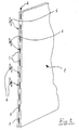
- a panel made for the wall assembly system can be made of any type of material and is provided with a plurality of slots 3 disposed staggered on a first side 2 and a second vertical side (not shown) of the panel.
- the slots 3 are engageable by a corresponding plurality of coupling elements 4, as indicated in Fig. 1 with the arrows which extend from the elements 4 to the corresponding slots 3; not all the elements 4 are shown in this figure, but it is understood that one slot corresponds to each element and vice versa.
- the coupling or constraining element 4 between two adjacent panels is physically separate from the panels and is normally disengaged from the panel and provided with at least two projecting portions to simultaneously engage two slots of two adjacent panels.
- the elements 4 are insertable in and removable from the slots by hand, that is, without using tools, as is instead generally the case in prior art.
- the slots 3 must be capable of receiving a part of the corresponding elements 4 and of retaining them.
- the slots are generally formed by a profile with structure and thicknesses such as to withstand the successive stresses transmitted thereto during use of the panel.
- the profile 5 shown in Figs. 2-5 presents a body 6 generally with a quadrangular section (in the embodiment shown it is rectangular) which is hollow and which presents a series of openings 7 produced staggered on only one side, 8, of said box-shaped body 6.
- a quadrangular section in the embodiment shown it is rectangular
- a series of openings 7 produced staggered on only one side, 8, of said box-shaped body 6.
- the openings 7 give access to the inner part of the hollow body 6 and in this manner form a plurality of slots obtained from a single profile.
- the slots are defined by the openings 7 on the side 8 of the profile 5, even if in actual fact there are no interruptions in the body 6 of the profile, which is a continuous structure without inner dividing walls.
- the profile also presents two L-shaped flanges 9, which extend from two adjacent sides of the box-shaped body 6 and have the function of constraining the profile to the panel and of stiffening the structure of the profile.
- the profile 5 is generally recessed in the vertical side 2 of the panel 1, and is therefore of the concealed type, being used to mutually constrain two panels on the same plane.
- the multiple profiles shown in Figs. 3 and 4 are preferably used; in these embodiments, which allow two panels to be mutually disposed at an angle, the body 6 of the profiles are part of a structure 10a and 10b to mutually connect two panels forming an angle.
- Fig. 3 allows angles of 90° and Fig. 4 angles of 45° to be obtained.
- FIGS 7 and 8 show in greater detail an element 4 for reciprocal coupling of panels according to the present invention.
- the coupling element 4 comprises a body 11 in the form of a parallelogram-shaped plate; two projecting portions 12 and 13 extend from opposite and alternate corners of the body 11, in opposite directions to form an extension of the greater sides of the parallelogram, that is, they extend along the longer sides thereof, and preferably in a symmetrical manner in order to be able to use either one or other of the projecting portions without distinction.
- the element 4 is partly housed in a slot of a panel and the projecting portions 12 and 13 have the function of each coupling a profile of a panel and maintaining them in contact, as shown in Fig. 7 . In substance, each element is housed half in one panel and half in the adjacent panel of the assembled wall.
- the portions 12 and 13 have the function of engaging the hollow part of the profile after having been inserted therein through the openings 7; once inserted, one of the portions, for example the portion 12, is positioned in the hollow part of the profile between the walls thereof.
- the dimensions of the portion 12 (and 13, as it is identical to the portion 12) are such that it can substantially engage the inner walls of the profile and in any case can be inserted in and removed from the body 6 of the profile without difficulty.
- the ratio between the width L of the projecting portions 12 and 13 (in plan view) and the width L1 of the portion of slot engaged by the projecting portion is in the interval from 0.85 to 0.99.
- Analogous values are preferably applied to the ratio of the other side, S, of the portions 12 and 13 with the other side, S1, of the body 6.
- the portions 12 and 13 extend inside the profile for a length sufficient to ensure that they cannot slip out of the body 6 of the profile 5.
- the distance L3 between the inner wall 14 and the outer wall 15 from the body 6 corresponds to approximately 50% of the total width L3 of the element 4.
- the coupling element or plate 4 has rounded and tapered tips of the projecting portions 12 and 13 ( Fig. 8 ), obtuse angles of the parallelogram in the interval from 160 to 190 degrees, and presents a right-angled portion 16 between the projecting portions 12 and 13 and the oblique side of the body 11.
- Fig. 10 shows the profiles of the two sides of a panel, i.e. the profiles 5 and 5A of two panels (not visible) which will be coupled by means of the coupling elements 4.
- the distance D1 between two adjacent openings 7 on one side of a panel it is preferable for the distance D1 between two adjacent openings 7 on one side of a panel to be less than the length D2 of the single openings 7.
- Fig. 11 shows a further object of the invention.
- the panel is formed by a laminate in which an inner layer 17 made of light material such as polystyrene or similar expanded material is coupled with two outer layers 18 and 19, for example made of PVC optionally coupled with nobler materials such as wood, and is enclosed in a frame 20 which stiffens it and which houses a profile 5 with the required openings and slots.
- This panel therefore combines qualities of lightness and stiffness with all the advantages offered by the mounting system described above and therefore is even simpler to assemble in partition walls.
- the system according to the invention can be used for various types of panels, including transparent glass panels or the like for a wide range of applications, including those for furnishing.
Landscapes
- Engineering & Computer Science (AREA)
- Architecture (AREA)
- Civil Engineering (AREA)
- Structural Engineering (AREA)
- Physics & Mathematics (AREA)
- Electromagnetism (AREA)
- Panels For Use In Building Construction (AREA)
Priority Applications (1)
| Application Number | Priority Date | Filing Date | Title |
|---|---|---|---|
| EP08018632A EP2180106A1 (de) | 2008-10-24 | 2008-10-24 | Montagesystem für Paneelwände |
Applications Claiming Priority (1)
| Application Number | Priority Date | Filing Date | Title |
|---|---|---|---|
| EP08018632A EP2180106A1 (de) | 2008-10-24 | 2008-10-24 | Montagesystem für Paneelwände |
Publications (1)
| Publication Number | Publication Date |
|---|---|
| EP2180106A1 true EP2180106A1 (de) | 2010-04-28 |
Family
ID=40467194
Family Applications (1)
| Application Number | Title | Priority Date | Filing Date |
|---|---|---|---|
| EP08018632A Withdrawn EP2180106A1 (de) | 2008-10-24 | 2008-10-24 | Montagesystem für Paneelwände |
Country Status (1)
| Country | Link |
|---|---|
| EP (1) | EP2180106A1 (de) |
Cited By (1)
| Publication number | Priority date | Publication date | Assignee | Title |
|---|---|---|---|---|
| NO20201443A1 (en) * | 2020-12-30 | 2022-07-01 | Moe Haavar | A Construction Assembly for Building a Modular Structure |
Citations (9)
| Publication number | Priority date | Publication date | Assignee | Title |
|---|---|---|---|---|
| DE1534746A1 (de) * | 1965-09-20 | 1969-09-04 | Const Roch Sarl Macornay | Vorrichtung zum Verbinden von Bauelementen |
| CH619278A5 (en) | 1976-12-13 | 1980-09-15 | Licencia Talalmanyokat | Room-enclosing structure, in particular for erecting exhibition areas |
| DE3330221A1 (de) * | 1983-08-22 | 1985-03-07 | Gerhard 7107 Neckarsulm Kaminski | Verbindungselement |
| FR2576764A1 (fr) | 1985-02-05 | 1986-08-08 | Marty Roger | Tubes articules pour le montage de supports d'expositions |
| GB2204890A (en) * | 1987-04-16 | 1988-11-23 | Ward Building Systems Ltd | Partitions comprising demountable panels and having junctions in the partitions |
| WO1990001594A1 (en) * | 1988-08-08 | 1990-02-22 | Upham Hill Christopher William | Connection system |
| EP0571993A1 (de) * | 1992-05-29 | 1993-12-01 | Haworth, Inc. | Demontierbares Pfosten-/Plattensystem |
| BE1009442A6 (fr) | 1995-06-28 | 1997-03-04 | Sprl Ateliers Primo | Systeme de construction a montage et demontage rapide pour ensemble plancher-cloison integre. |
| US20010037612A1 (en) | 1997-12-24 | 2001-11-08 | Michael J. Striker | Wall system, in particular exhibition halls |
-
2008
- 2008-10-24 EP EP08018632A patent/EP2180106A1/de not_active Withdrawn
Patent Citations (9)
| Publication number | Priority date | Publication date | Assignee | Title |
|---|---|---|---|---|
| DE1534746A1 (de) * | 1965-09-20 | 1969-09-04 | Const Roch Sarl Macornay | Vorrichtung zum Verbinden von Bauelementen |
| CH619278A5 (en) | 1976-12-13 | 1980-09-15 | Licencia Talalmanyokat | Room-enclosing structure, in particular for erecting exhibition areas |
| DE3330221A1 (de) * | 1983-08-22 | 1985-03-07 | Gerhard 7107 Neckarsulm Kaminski | Verbindungselement |
| FR2576764A1 (fr) | 1985-02-05 | 1986-08-08 | Marty Roger | Tubes articules pour le montage de supports d'expositions |
| GB2204890A (en) * | 1987-04-16 | 1988-11-23 | Ward Building Systems Ltd | Partitions comprising demountable panels and having junctions in the partitions |
| WO1990001594A1 (en) * | 1988-08-08 | 1990-02-22 | Upham Hill Christopher William | Connection system |
| EP0571993A1 (de) * | 1992-05-29 | 1993-12-01 | Haworth, Inc. | Demontierbares Pfosten-/Plattensystem |
| BE1009442A6 (fr) | 1995-06-28 | 1997-03-04 | Sprl Ateliers Primo | Systeme de construction a montage et demontage rapide pour ensemble plancher-cloison integre. |
| US20010037612A1 (en) | 1997-12-24 | 2001-11-08 | Michael J. Striker | Wall system, in particular exhibition halls |
Cited By (2)
| Publication number | Priority date | Publication date | Assignee | Title |
|---|---|---|---|---|
| NO20201443A1 (en) * | 2020-12-30 | 2022-07-01 | Moe Haavar | A Construction Assembly for Building a Modular Structure |
| NO346454B1 (en) * | 2020-12-30 | 2022-08-22 | Moe Haavar | A Construction Assembly for Building a Modular Structure |
Similar Documents
| Publication | Publication Date | Title |
|---|---|---|
| US8733851B2 (en) | Modular furniture system | |
| US5983574A (en) | Merchandise display panel | |
| US4118903A (en) | Partitions and screens | |
| US9366030B2 (en) | Wall panel system | |
| US9828769B2 (en) | Foldable brick with rope attachments and detachable wall building system | |
| US10086304B1 (en) | Modular panel system for interactive play or display | |
| US11661736B2 (en) | Modular wall panels and system | |
| US10400449B2 (en) | Partitioning system for temporary and flexible-use structures | |
| US5016417A (en) | Modular universal construction units employing flexible web with interlockable heads | |
| US7017311B2 (en) | Panel for modular construction | |
| US20200040565A1 (en) | Accessory dwelling and/or storage structures and related construction methods | |
| US4058909A (en) | Construction kit | |
| US8967739B2 (en) | Modular exhibit structure | |
| US6418681B1 (en) | Modular temporary barrier system comprising foam core panels with peg-receiving apertures on the sides and u-shaped connector receiving portions on the top and bottom | |
| WO1987003321A1 (en) | Panel structures | |
| US11085182B2 (en) | Modular wall panels and system | |
| US20060059824A1 (en) | Block structure | |
| EP2180106A1 (de) | Montagesystem für Paneelwände | |
| JP2841271B2 (ja) | 間仕切り装置 | |
| EP3584379A1 (de) | Verbessertes modulares gebäude und segmente | |
| US20230081024A1 (en) | System for producing room elements such as walls | |
| CA2671579C (en) | Modular exhibit structure | |
| CA3154994A1 (en) | Modular wall panels and system | |
| AU2011100137A4 (en) | Panel for a modular panel system | |
| WO2003062547A1 (en) | Demountable wall assembly |
Legal Events
| Date | Code | Title | Description |
|---|---|---|---|
| PUAI | Public reference made under article 153(3) epc to a published international application that has entered the european phase |
Free format text: ORIGINAL CODE: 0009012 |
|
| AK | Designated contracting states |
Kind code of ref document: A1 Designated state(s): AT BE BG CH CY CZ DE DK EE ES FI FR GB GR HR HU IE IS IT LI LT LU LV MC MT NL NO PL PT RO SE SI SK TR |
|
| AX | Request for extension of the european patent |
Extension state: AL BA MK RS |
|
| AKY | No designation fees paid | ||
| REG | Reference to a national code |
Ref country code: DE Ref legal event code: 8566 |
|
| STAA | Information on the status of an ep patent application or granted ep patent |
Free format text: STATUS: THE APPLICATION IS DEEMED TO BE WITHDRAWN |
|
| 18D | Application deemed to be withdrawn |
Effective date: 20101029 |