EP2179969B1 - Speicherbehälter für eine Flüssigkeit - Google Patents
Speicherbehälter für eine Flüssigkeit Download PDFInfo
- Publication number
- EP2179969B1 EP2179969B1 EP09173400.4A EP09173400A EP2179969B1 EP 2179969 B1 EP2179969 B1 EP 2179969B1 EP 09173400 A EP09173400 A EP 09173400A EP 2179969 B1 EP2179969 B1 EP 2179969B1
- Authority
- EP
- European Patent Office
- Prior art keywords
- tank
- rigid member
- liquid
- storing
- contact surface
- Prior art date
- Legal status (The legal status is an assumption and is not a legal conclusion. Google has not performed a legal analysis and makes no representation as to the accuracy of the status listed.)
- Active
Links
- 239000007788 liquid Substances 0.000 title claims description 47
- RYGMFSIKBFXOCR-UHFFFAOYSA-N Copper Chemical compound [Cu] RYGMFSIKBFXOCR-UHFFFAOYSA-N 0.000 claims description 38
- 239000010949 copper Substances 0.000 claims description 36
- 229910052802 copper Inorganic materials 0.000 claims description 36
- 230000000844 anti-bacterial effect Effects 0.000 claims description 29
- XLYOFNOQVPJJNP-UHFFFAOYSA-N water Substances O XLYOFNOQVPJJNP-UHFFFAOYSA-N 0.000 claims description 29
- 229910000881 Cu alloy Inorganic materials 0.000 claims description 13
- 238000004140 cleaning Methods 0.000 claims description 12
- 239000000463 material Substances 0.000 claims description 10
- 238000000034 method Methods 0.000 claims description 5
- 239000010935 stainless steel Substances 0.000 claims description 3
- 229910001220 stainless steel Inorganic materials 0.000 claims description 3
- 239000004698 Polyethylene Substances 0.000 claims description 2
- 239000004033 plastic Substances 0.000 claims description 2
- 229920003023 plastic Polymers 0.000 claims description 2
- -1 polyethylene Polymers 0.000 claims description 2
- 229920000573 polyethylene Polymers 0.000 claims description 2
- 239000010410 layer Substances 0.000 description 10
- 241000894006 Bacteria Species 0.000 description 7
- 239000003651 drinking water Substances 0.000 description 7
- 235000020188 drinking water Nutrition 0.000 description 7
- QPLDLSVMHZLSFG-UHFFFAOYSA-N Copper oxide Chemical compound [Cu]=O QPLDLSVMHZLSFG-UHFFFAOYSA-N 0.000 description 6
- 239000005751 Copper oxide Substances 0.000 description 6
- 229910000431 copper oxide Inorganic materials 0.000 description 6
- 230000003647 oxidation Effects 0.000 description 4
- 238000007254 oxidation reaction Methods 0.000 description 4
- KRKNYBCHXYNGOX-UHFFFAOYSA-N citric acid Chemical compound OC(=O)CC(O)(C(O)=O)CC(O)=O KRKNYBCHXYNGOX-UHFFFAOYSA-N 0.000 description 3
- 230000035755 proliferation Effects 0.000 description 3
- 230000001419 dependent effect Effects 0.000 description 2
- 210000000056 organ Anatomy 0.000 description 2
- 239000000126 substance Substances 0.000 description 2
- 210000002700 urine Anatomy 0.000 description 2
- 238000005406 washing Methods 0.000 description 2
- JPVYNHNXODAKFH-UHFFFAOYSA-N Cu2+ Chemical compound [Cu+2] JPVYNHNXODAKFH-UHFFFAOYSA-N 0.000 description 1
- 229910000831 Steel Inorganic materials 0.000 description 1
- 238000005299 abrasion Methods 0.000 description 1
- 229910001431 copper ion Inorganic materials 0.000 description 1
- 238000000605 extraction Methods 0.000 description 1
- 239000000835 fiber Substances 0.000 description 1
- 238000012423 maintenance Methods 0.000 description 1
- 235000019645 odor Nutrition 0.000 description 1
- 230000001590 oxidative effect Effects 0.000 description 1
- 238000000746 purification Methods 0.000 description 1
- 238000007789 sealing Methods 0.000 description 1
- 239000010959 steel Substances 0.000 description 1
- 239000002344 surface layer Substances 0.000 description 1
Images
Classifications
-
- C—CHEMISTRY; METALLURGY
- C02—TREATMENT OF WATER, WASTE WATER, SEWAGE, OR SLUDGE
- C02F—TREATMENT OF WATER, WASTE WATER, SEWAGE, OR SLUDGE
- C02F1/00—Treatment of water, waste water, or sewage
- C02F1/50—Treatment of water, waste water, or sewage by addition or application of a germicide or by oligodynamic treatment
- C02F1/505—Treatment of water, waste water, or sewage by addition or application of a germicide or by oligodynamic treatment by oligodynamic treatment
-
- C—CHEMISTRY; METALLURGY
- C02—TREATMENT OF WATER, WASTE WATER, SEWAGE, OR SLUDGE
- C02F—TREATMENT OF WATER, WASTE WATER, SEWAGE, OR SLUDGE
- C02F2201/00—Apparatus for treatment of water, waste water or sewage
- C02F2201/001—Build in apparatus for autonomous on board water supply and wastewater treatment (e.g. for aircrafts, cruiseships, oil drilling platforms, railway trains, space stations)
Definitions
- the copper of the contact surface oxidizes on contact with the liquid and the copper ions thus created come to deactivate and / or kill the bacteria contained in the liquid and therefore prevent the proliferation of bacteria in this liquid.
- Such a tank makes it possible to avoid the proliferation of bacteria in a liquid without energy supply and to avoid chemical treatment of the liquid.
- This tank is intended to purify the urine contained in a tank.
- the bactericidal medium is in the form of an element consisting of copper fibers from 10 to 500 micrometers. This element is introduced inside the tank in order to remove bad odors and eliminate bacteria contained in the urine.
- the bactericidal means is suitable for being used several times because it is possible to wash the fibrous copper element with water.
- a tank is not efficient enough to prevent the proliferation of bacteria in a tank capable of being filled and emptied a multitude of times.
- a layer of copper oxide is formed on the surface of the bactericidal copper medium. This layer prevents the oxidation of copper and the bactericidal medium loses its bactericidal properties. It is necessary to remove this layer of copper oxide so that the copper-based bactericidal medium retains its bactericidal properties.
- washing with water does not make it possible to remove the layer of copper oxide.
- An object of the invention is to provide a storage tank which does not have the aforementioned drawbacks.
- Another object of the invention is to provide a tank for storing a liquid in which it is possible to store a liquid at a lower cost.
- the invention relates to a storage tank according to claim 1.
- the liquid storage tank has one or more of the characteristics of the dependent claims 2 to 12, taken alone or in any technically possible combination.
- the invention further relates to a method for storing a liquid in a liquid storage tank as defined above, according to claim 13.
- the liquid storage tank has one or more of the characteristics of dependent claims 14 or 15, taken alone or in any technically possible combination.
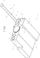
- FIG. 1 there is shown a perspective view of the storage tank for a liquid 3 contained in a tank 2.
- the tank 2 is, for example, installed in toilets, in particular in the toilets of a railway vehicle, in order to store a liquid, for example drinking water.
- a reservoir 1 for storing drinking water 3 will be described, but the invention can be applied to a reservoir containing any other liquid which is more oxidizing than copper.
- the tank 2 is filled with water through the orifice 1 6.
- the water thus stored is capable of being drawn from the orifice 17 to supply a tap with drinking water.
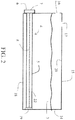
- the tank 2 comprises an internal surface 20, visible on the figure 2 , made of a less reducing material than copper or a copper alloy.
- the internal surface 20 of the tank 2 is made of material of the plastic material type, for example polyethylene or stainless steel.
- the tank 2 is made of a single material further constituting the internal surface 20.
- the tank 2 is inexpensive and easy to produce compared to a copper or copper alloy tank.
- the tanks installed in the sanitary facilities of railway vehicles are generally filled with water when the vehicle is in storage.
- the water in the tank if it is not drawn off by the tap, may have to stagnate for one or more days in the tank before being renewed.
- the bacteria present in the water are likely to proliferate in this standing water.
- the water storage tank 1 3 comprises several bactericidal means 4.
- a single bactericidal means 4 is shown on the figure 2 .
- a bactericidal means 4 comprises a rigid organ 5 comprising a contact surface 22 with water 3.
- the external contact surface 22 of the rigid member 5 is made of copper alloy or copper.
- the rigid member 5 consists of copper or of a copper alloy of which the contact surface 22 with water 3 is also made up.
- the rigid member consists of a rigid internal member made of a material different from copper or a copper alloy, said internal member being covered with a layer of copper or a copper alloy.
- the contact surface 22 is the surface of the layer of copper or a copper alloy deposited on the internal member.
- the rigid member 5 of a bactericidal means 4 is placed inside the tank 2 to conserve the water 3 contained in the copper.
- a rigid member 5 is introduced into the tank 2 to conserve the water 3, contained in this tank 2, which is drinkable.
- a bactericidal means 4 is shown outside of the tank 2.
- Three bactericidal means 4 are represented, on the figure 2 , in the water purification position.
- a rigid member 5 is produced in the form of a hollow element so as to provide a larger contact surface 22 with water.
- the hollow rigid member 5 has a shape of conduit so as to provide a contact surface 22 comprising an internal contact surface, not visible on the figures 1 and 2 , and an external contact surface with water.
- the rigid member 5 is capable of being mechanically cleaned.
- the rigid member 5 is a member with a diameter greater than or equal to 20mm.
- the latter has, for example, a thickness greater than a predetermined threshold depending on the rigidity of the material from which the member is made.
- a rigid member has, for example, a thickness greater than 0.5 mm.
- the rigid member 10 5 is equipped with means 8 for improving the circulation of water against said copper element 8.
- the means 8 for improving the circulation of water against the contact surface of the rigid member 5 are produced in the form of orifices 8 distributed over the entire length of the rigid member 5.
- the orifices 8 promote the oxidation of copper and the performance of the tank to deactivate and / or kill the bacteria contained in the liquid 3.
- the rigid members 5 are placed in the lower part of the tank 2. In this way, these elements 20 are immersed in standing water 3 and conserve drinking water, even when the tank 2 contains little water 3.
- the bactericidal means 4 is fixed to a side wall 14 of the cvue 2 so that the rigid member 5 extends in the horizontal direction at the bottom of the tank 2.
- a bactericidal means 4 is fixed to an upper wall 1 5 or lower 1 8 of the tank 2 so that the associated rigid member 5 extends from the bottom of the tank 2 towards the top of the tank.
- the contact surface 22 in contact with the water 3 is smaller than in the previous embodiment.
- Each bactericidal means 4 is removable. Each bactericidal means 4 can be inserted into the tank 2 and removed therefrom.
- the tank 2 comprises several passages 11 between the interior and the exterior of the tank 2.
- a passage 11 makes it possible to introduce a rigid member 5 into the tank 2 and to remove the latter from the tank 2.
- a passage 11 is made, in the embodiment shown in the figure 1 , in the form of a hole drilled in the wall of the tank 2.
- Each orifice 11 has a larger section or substantially identical to the section of a rigid member 5.
- a bactericidal means 4 comprises a gripping means 6 which allows an operator to insert, from the outside of the tank, the copper element inside the tank 2 through a passage 1 1 and to withdraw, from outside the tank, this same copper element 5 from the tank by said passage means 11.
- the gripping means 6 opens onto the outside of the tank 2. The gripping means 6 gives access to the rigid member 5 from the outside of the tank 2.
- closure means 7 fixed in leaktight manner to a wall of the tank 2.
- the closure means 7 is fixed to the wall, for example by means of screws or any other removable fixing means.
- the gripping means 6 forms the closing means 7.
- a gripping means 6 is fixed to the end of a copper element 5. It is, for example, screwed to the copper element.
- a gripping means 6 is a non-cupric element, for example stainless steel. In this way, the cost of the tank is limited.
- a gripping means 6 is a copper or copper alloy element.
- the gripping means 6 and the rigid member 5 form a one-piece copper element.
- a gripping means 6 has a cross section greater than that of the orifice 1 1 so as to lead to the outside of the tank when the rigid member 5 is inserted into the tank 2.
- the gripping means 6 has a double function of tightly closing a passage 11 and gripping the rigid member 5.
- the attachment of the gripping means 6 to the tank also keeps the rigid member 5 in a fixed position, inside the tank 2.
- a fixing means 19 is provided for the end of the rigid member 5 opposite the gripping means.
- This fixing means 19 is a stud fixed to the wall opposite the first wall, into which the rigid member 5 is fitted.
- the fixing means 1 9 improves the fixity of the rigid member 5.
- the gripping means 6 are fixed to a side wall 14 of the tank 2.
- the contact surface 22 of the rigid member 5 extends in the horizontal direction, between two side walls 14 facing each other.
- the gripping means 6 is fixed to the upper 15 or lower 18 wall of the tank 2.
- the attachment of the gripping means 6 to the upper wall 15 of the tank ensures good sealing because the closing means 7 of the passage 11 is not in contact with water as soon as the tank 2 is not completely filled of water 3.
- a rigid member 5 is inserted into the tank 2 by pushing the rigid member 5 into a passage 11 by means of the gripping means 6.
- the passage 11 is then closed by fixing the closure means 7 to the wall 14 of the tank 2.
- the gripping means 6 constituting the closing means 7 the rigid member 5 is pushed into the tank 2 until the gripping means 6 is glued to a wall of the tank 2 and forms a closure plug of the passage 11.
- the gripping means 6 is then fixed to the wall 7.
- the rigid member 5 is thus in the position for purifying the liquid which comes into contact with its contact surface 22.
- one solution consists in washing the surface 22 of the rigid member 5 with a chemical of the citric acid type or in a mechanical cleaning of the contact surface of the rigid member.
- Mechanical cleaning of a rigid member 5 consists, for example, in rubbing the latter using a brush made of a material harder than copper, for example, a steel brush or any other abrasive element.
- This type of cleaning makes it possible to remove, by abrasion, the layer of copper oxide formed on the surface of a rigid member 5, during the oxidation of copper.
- the rigid member 5 is extracted from the tank 2 by opening a passage 11.
- the passage 11 is opened by separating the closing means 7 from the tank 2.
- the gripping means 6 are pulled from outside the tank 2 to extract the rigid member 5 from the tank 2, through the passage 11.
- a liquid storage tank according to the invention has the advantage of keeping a large quantity of liquid at lower costs. Such a tank ensures the conservation of a liquid over several filling and emptying cycles of the tank. Mechanical cleaning of the rigid member ensures such conservation at low cost.
- a rigid member is accessible from outside the tank to clean said member or exchange it with another rigid member.
- the large size or diameter of the rigid element facilitates mechanical cleaning of its surface.
- Such a member also has a large contact surface with the liquid.
- a large thickness of the rigid member reinforces the rigidity of the latter so as to facilitate mechanical cleaning of its surface.
Landscapes
- Life Sciences & Earth Sciences (AREA)
- Hydrology & Water Resources (AREA)
- Engineering & Computer Science (AREA)
- Environmental & Geological Engineering (AREA)
- Water Supply & Treatment (AREA)
- Chemical & Material Sciences (AREA)
- Organic Chemistry (AREA)
- Details Of Rigid Or Semi-Rigid Containers (AREA)
- Apparatus For Disinfection Or Sterilisation (AREA)
- Agricultural Chemicals And Associated Chemicals (AREA)
Claims (15)
- Speicherbehälter (1) für eine Flüssigkeit (3), aufweisend:- ein Speichergefäß (2) für die besagte Flüssigkeit (3), dessen innere Fläche (20) aus einem Material, das weniger reduzierend ist als Kupfer, zusammengesetzt ist, wobei das Gefäß wenigstens eine erste Wand aufweist, insbesondere eine Seitenwand (14), untere Wand (18) oder obere Wand (15),- wenigstens ein bakterizides Mittel (4), welches eine Kontaktfläche (22) mit besagter Flüssigkeit (3) aufweist, wobei besagte Kontaktfläche (22) aus Kupfer oder einer Kupferlegierung zusammengesetzt ist,dadurch gekennzeichnet, dass:- die Kontaktfläche (22) die Fläche eines starren Organs (5) ist, das an der Innenseite des besagten Gefäßes (2) angeordnet ist,- das Gefäß (2) für jedes starre Organ (5) einen Durchlass (11) in Form einer Öffnung, die die erste Wand (14, 18, 15) durchdringt, aufweist, welcher das Passieren des besagten starren Organs (5) zwischen der Innenseite und der Außenseite des Gefäßes (2) ermöglicht,- wenigstens ein bakterizides Mittel (4) ein starres Organ (5) aufweist, das in Form eines hohlen Elements realisiert ist, insbesondere in Form eines Rohrs, das eine innere Kontaktfläche und eine äußere Kontaktfläche mit Wasser aufweist.
- Speicherbehälter (1) für eine Flüssigkeit (3) gemäß dem vorangegangenen Anspruch, dadurch gekennzeichnet, dass wenigstens ein bakterizides Mittel (4) herausnehmbar ist.
- Speicherbehälter (1) für eine Flüssigkeit (3) gemäß irgendeinem der vorangegangenen Ansprüche, dadurch gekennzeichnet, dass wenigstens ein bakterizides Mittel (4) ein starres Organ (5) mit einem Durchmesser größer oder gleich 20 mm aufweist.
- Speicherbehälter (1) für eine Flüssigkeit (3) gemäß irgendeinem der vorangegangenen Ansprüche, dadurch gekennzeichnet, dass wenigstens ein bakterizides Mittel (4) ein starres Organ (5) mit einer Dicke größer als 0,5 mm aufweist.
- Speicherbehälter (1) für eine Flüssigkeit (3) gemäß irgendeinem der vorangegangenen Ansprüche, dadurch gekennzeichnet, dass wenigstens ein bakterizides Mittel (4) ein starres Organ (5) aufweist, das mit Mitteln (8) zum Verbessern der Wasserzirkulation gegen besagtes starres Organ (5) ausgestattet ist.
- Speicherbehälter (1) für eine Flüssigkeit (3) gemäß dem vorangegangenen Anspruch, dadurch gekennzeichnet, dass die Mittel (8) zum Verbessern der Wasserzirkulation gegen das starre Organ (5) in Form von Öffnungen realisiert sind, die über die ganze Länge des besagten Organs (5) verteilt sind.
- Speicherbehälter (1) für eine Flüssigkeit (3) gemäß einem der vorangegangenen Ansprüche, dadurch gekennzeichnet, dass wenigstens ein bakterizides Mittel (4) ein Handhabe-Mittel (6) aufweist, das auf der Außenseite des Gefäßes (2) mündet, wenn besagtes starres Organ (5) in das Gefäß (2) eingefügt ist.
- Speicherbehälter (1) für eine Flüssigkeit (3) gemäß einem der vorangegangenen Ansprüche, dadurch gekennzeichnet, dass das Gefäß (2) eine zweite Wand aufweist, die gegenüber der ersten Wand ist, wobei Mittel (19) zur Befestigung eines Endes des starren Organs (5) an dieser zweiten Wand angeordnet sind.
- Speicherbehälter (1) für eine Flüssigkeit (3) gemäß irgendeinem der vorangegangenen Ansprüche, dadurch gekennzeichnet, dass er ein Verschlussmittel (7) für jeden Durchlass (11) aufweist.
- Speicherbehälter (1) für eine Flüssigkeit (3) gemäß Anspruch 9, dadurch gekennzeichnet, dass wenigstens ein Verschlussmittel (7) aus einem Handhabe-Mittel (6) gebildet ist.
- Speicherbehälter (1) für eine Flüssigkeit (3) gemäß einem der vorangegangenen Ansprüche, dadurch gekennzeichnet, dass wenigstens eines der besagten bakteriziden Mittel (4) derart angeordnet ist, dass das starre Organ (5) sich im unteren Teil des Gefäßes (2) erstreckt.
- Speicherbehälter (1) für eine Flüssigkeit (3) gemäß einem der vorangegangenen Ansprüche, dadurch gekennzeichnet, dass die innere Fläche (20) des Speichergefäßes (2) aus Kunststoffmaterial realisiert ist, insbesondere aus Polyethylen oder rostfreiem Stahl.
- Verfahren zum Speichern einer Flüssigkeit (3) in einem Speicherbehälter (1) für eine Flüssigkeit (3) gemäß einem der vorangegangenen Ansprüche, dadurch gekennzeichnet, dass es die folgenden Schritte aufweist:- Einfügen eines starren Organs (5), welches eine Kontaktfläche (22) aufweist, die aus Kupfer oder einer Kupferlegierung zusammengesetzt ist, in das Gefäß (2) durch einen Durchlass (11) hindurch, der in der ersten Seitenwand (14) des Gefäßes (2) vorgesehen ist,- Füllen des Gefäßes (2) mit der Flüssigkeit (3),- Reinigen der Kontaktfläche (22) oder Ersetzen der Kontaktfläche (22) durch eine gleichartige Kontaktfläche (22) oder Ersetzen des starren Organs (22) durch ein gleichartiges, starres Organ (22).
- Verfahren zum Speichern einer Flüssigkeit (3) in einem Speicherbehälter (1) für eine Flüssigkeit gemäß dem vorangegangenen Anspruch, dadurch gekennzeichnet, dass das Reinigen der Kontaktfläche (22) ein mechanisches Reinigen ist.
- Verfahren zum Speichern einer Flüssigkeit (3) gemäß Anspruch 13 oder 14, dadurch gekennzeichnet, dass:- vor dem Schritt des mechanischen Reinigens der Kontaktfläche (22) oder des Ersetzens der Kontaktfläche (22) durch eine gleichartige Kontaktfläche (22) oder des Ersetzens des starren Organs (22) durch ein gleichartiges, starres Organ (22) ein Schritt des Entfernens des starren Elements (5) aus dem Gefäß (2) von der Außenseite des Gefäßes (2) her realisiert wird,- nach dem Schritt des mechanischen Reinigens der Kontaktfläche (22) oder des Ersetzens der Kontaktfläche (22) durch eine gleichartige Kontaktfläche (22) oder des Ersetzens des starren Organs (22) durch ein gleichartiges, starres Organ (22) ein Schritt des Einfügen eines starren Organs (5) in das Gefäß (2) von der Außenseite des Gefäßes (2) her realisiert wird.
Applications Claiming Priority (1)
| Application Number | Priority Date | Filing Date | Title |
|---|---|---|---|
| FR0857172A FR2937312B1 (fr) | 2008-10-22 | 2008-10-22 | Reservoir de stockage d'un liquide |
Publications (2)
| Publication Number | Publication Date |
|---|---|
| EP2179969A1 EP2179969A1 (de) | 2010-04-28 |
| EP2179969B1 true EP2179969B1 (de) | 2020-01-15 |
Family
ID=40873298
Family Applications (1)
| Application Number | Title | Priority Date | Filing Date |
|---|---|---|---|
| EP09173400.4A Active EP2179969B1 (de) | 2008-10-22 | 2009-10-19 | Speicherbehälter für eine Flüssigkeit |
Country Status (4)
| Country | Link |
|---|---|
| EP (1) | EP2179969B1 (de) |
| ES (1) | ES2779027T3 (de) |
| FR (1) | FR2937312B1 (de) |
| RU (1) | RU2520004C2 (de) |
Citations (1)
| Publication number | Priority date | Publication date | Assignee | Title |
|---|---|---|---|---|
| GB2419590A (en) * | 2004-10-14 | 2006-05-03 | Tanya Yvonne Paston | Water disinfection apparatus and method |
Family Cites Families (6)
| Publication number | Priority date | Publication date | Assignee | Title |
|---|---|---|---|---|
| US3539507A (en) * | 1968-10-31 | 1970-11-10 | Energy Systems Inc | Waste treatment process |
| US3788476A (en) * | 1971-09-23 | 1974-01-29 | D Othmer | Sewage treatment system |
| US3870634A (en) * | 1972-06-01 | 1975-03-11 | Frank Humphrey | Marine sewage treatment system for water craft |
| US6207047B1 (en) * | 1996-11-05 | 2001-03-27 | Sea Sanitizer International, L.L.C. | Wastewater treatment system |
| US7427355B2 (en) * | 2004-05-14 | 2008-09-23 | Yiu Chau Chau | Water treatment unit for bottle or pitcher |
| JP2008067728A (ja) | 2006-09-12 | 2008-03-27 | Niigata Shiki Kogyo Kk | 簡易式小便浄化装置 |
-
2008
- 2008-10-22 FR FR0857172A patent/FR2937312B1/fr not_active Expired - Fee Related
-
2009
- 2009-10-19 ES ES09173400T patent/ES2779027T3/es active Active
- 2009-10-19 EP EP09173400.4A patent/EP2179969B1/de active Active
- 2009-10-21 RU RU2009138976/12A patent/RU2520004C2/ru active
Patent Citations (1)
| Publication number | Priority date | Publication date | Assignee | Title |
|---|---|---|---|---|
| GB2419590A (en) * | 2004-10-14 | 2006-05-03 | Tanya Yvonne Paston | Water disinfection apparatus and method |
Also Published As
| Publication number | Publication date |
|---|---|
| FR2937312A1 (fr) | 2010-04-23 |
| RU2009138976A (ru) | 2011-04-27 |
| FR2937312B1 (fr) | 2013-07-05 |
| EP2179969A1 (de) | 2010-04-28 |
| RU2520004C2 (ru) | 2014-06-20 |
| ES2779027T3 (es) | 2020-08-13 |
Similar Documents
| Publication | Publication Date | Title |
|---|---|---|
| FR2584941A1 (fr) | Cartouche tubulaire filtrante et son application a la fabrication de vin mousseux en bouteille | |
| EP2179969B1 (de) | Speicherbehälter für eine Flüssigkeit | |
| WO2007101938A1 (fr) | Systeme de distribution et de recuperation de liquides et dispositif le comportant | |
| FR2792665A1 (fr) | Cuve a dechets a depression | |
| CA2607923A1 (fr) | Dispositif de bouchage d'un col de recipient, recipient equipe d'un tel dispositif, procede de bouchage d'un tel recipient et procede de fabrication d'un tel dispositif | |
| FR2973212A3 (fr) | Dispositif pour l'elimination des eaux residuaires pour wc chimiques de camping-cars ou de caravanes | |
| FR2579647A1 (fr) | Procede de distribution d'une solution coloree destinee au nettoyage et/ou a la desinfection de cuvettes de toilettes et dispositifs pour sa mise en oeuvre | |
| FR2474458A1 (fr) | Systeme de nettoyage de cuvettes de water-closets constitue par un receptacle dispose dans le reservoir d'eau associe a la cuvette | |
| FR2886286A1 (fr) | Element de filtration pour carafe d'eau | |
| EP1480896A2 (de) | Zubehör für behälter von flüssigen nahrungsmittel insbesondere wasser | |
| FR2818670A1 (fr) | Dispositif de vidange pour une machine a laver et procede pour le fonctionnement d'une machine a laver comportant un tel dispositif | |
| FR3005044A1 (fr) | Reservoir a filtre integre et appareil de distribution de boisson comprenant un tel reservoir | |
| FR2714279A1 (fr) | Cafetière électrique. | |
| FR2759569A1 (fr) | Dispositif modulaire porte-balai desinfectant et desodorisant et procede utilisant le dispositif | |
| FR2884720A1 (fr) | Dispositif de traitement de l'air | |
| FR2977598A1 (fr) | Manchon anti-odeur pour extremite de tuyau d'evacuation de liquide et installation associee | |
| FR2731900A1 (fr) | Urinal de securite perfectionne | |
| FR3158324A3 (fr) | Dispositif d'assainissement pour cuvettes de toilettes et tablette correspondante | |
| FR2731882A1 (fr) | Balai | |
| KR200221019Y1 (ko) | 냉온수기용 온수통의 구조 | |
| EP2142316B1 (de) | Kammer zum waschen des ausgiessablaufs eines milchlagerungs- und -kühlbehälters | |
| BE569081A (de) | ||
| JPH0246523Y2 (de) | ||
| CH361250A (fr) | Dispositif pour la désinfection ou la désodorisation d'un tuyau d'écoulement | |
| FR2804143A1 (fr) | Dispositif de garnissage pour couvercle de reservoir de chasse d'eau et reservoir de chasse d'eau correspondant |
Legal Events
| Date | Code | Title | Description |
|---|---|---|---|
| PUAI | Public reference made under article 153(3) epc to a published international application that has entered the european phase |
Free format text: ORIGINAL CODE: 0009012 |
|
| AK | Designated contracting states |
Kind code of ref document: A1 Designated state(s): AT BE BG CH CY CZ DE DK EE ES FI FR GB GR HR HU IE IS IT LI LT LU LV MC MK MT NL NO PL PT RO SE SI SK SM TR |
|
| 17P | Request for examination filed |
Effective date: 20101028 |
|
| 17Q | First examination report despatched |
Effective date: 20101126 |
|
| RAP1 | Party data changed (applicant data changed or rights of an application transferred) |
Owner name: ALSTOM TRANSPORT TECHNOLOGIES |
|
| RAP1 | Party data changed (applicant data changed or rights of an application transferred) |
Owner name: ALSTOM TRANSPORT TECHNOLOGIES SAS |
|
| RAP1 | Party data changed (applicant data changed or rights of an application transferred) |
Owner name: ALSTOM TRANSPORT TECHNOLOGIES |
|
| RAP1 | Party data changed (applicant data changed or rights of an application transferred) |
Owner name: ALSTOM TRANSPORT TECHNOLOGIES |
|
| STAA | Information on the status of an ep patent application or granted ep patent |
Free format text: STATUS: EXAMINATION IS IN PROGRESS |
|
| GRAP | Despatch of communication of intention to grant a patent |
Free format text: ORIGINAL CODE: EPIDOSNIGR1 |
|
| STAA | Information on the status of an ep patent application or granted ep patent |
Free format text: STATUS: GRANT OF PATENT IS INTENDED |
|
| INTG | Intention to grant announced |
Effective date: 20190819 |
|
| GRAS | Grant fee paid |
Free format text: ORIGINAL CODE: EPIDOSNIGR3 |
|
| GRAA | (expected) grant |
Free format text: ORIGINAL CODE: 0009210 |
|
| STAA | Information on the status of an ep patent application or granted ep patent |
Free format text: STATUS: THE PATENT HAS BEEN GRANTED |
|
| AK | Designated contracting states |
Kind code of ref document: B1 Designated state(s): AT BE BG CH CY CZ DE DK EE ES FI FR GB GR HR HU IE IS IT LI LT LU LV MC MK MT NL NO PL PT RO SE SI SK SM TR |
|
| REG | Reference to a national code |
Ref country code: CH Ref legal event code: EP Ref country code: GB Ref legal event code: FG4D Free format text: NOT ENGLISH |
|
| REG | Reference to a national code |
Ref country code: IE Ref legal event code: FG4D Free format text: LANGUAGE OF EP DOCUMENT: FRENCH |
|
| REG | Reference to a national code |
Ref country code: DE Ref legal event code: R096 Ref document number: 602009060991 Country of ref document: DE |
|
| REG | Reference to a national code |
Ref country code: AT Ref legal event code: REF Ref document number: 1225003 Country of ref document: AT Kind code of ref document: T Effective date: 20200215 |
|
| REG | Reference to a national code |
Ref country code: NL Ref legal event code: MP Effective date: 20200115 |
|
| REG | Reference to a national code |
Ref country code: LT Ref legal event code: MG4D |
|
| PG25 | Lapsed in a contracting state [announced via postgrant information from national office to epo] |
Ref country code: NL Free format text: LAPSE BECAUSE OF FAILURE TO SUBMIT A TRANSLATION OF THE DESCRIPTION OR TO PAY THE FEE WITHIN THE PRESCRIBED TIME-LIMIT Effective date: 20200115 Ref country code: PT Free format text: LAPSE BECAUSE OF FAILURE TO SUBMIT A TRANSLATION OF THE DESCRIPTION OR TO PAY THE FEE WITHIN THE PRESCRIBED TIME-LIMIT Effective date: 20200607 Ref country code: FI Free format text: LAPSE BECAUSE OF FAILURE TO SUBMIT A TRANSLATION OF THE DESCRIPTION OR TO PAY THE FEE WITHIN THE PRESCRIBED TIME-LIMIT Effective date: 20200115 Ref country code: NO Free format text: LAPSE BECAUSE OF FAILURE TO SUBMIT A TRANSLATION OF THE DESCRIPTION OR TO PAY THE FEE WITHIN THE PRESCRIBED TIME-LIMIT Effective date: 20200415 |
|
| REG | Reference to a national code |
Ref country code: ES Ref legal event code: FG2A Ref document number: 2779027 Country of ref document: ES Kind code of ref document: T3 Effective date: 20200813 |
|
| PG25 | Lapsed in a contracting state [announced via postgrant information from national office to epo] |
Ref country code: HR Free format text: LAPSE BECAUSE OF FAILURE TO SUBMIT A TRANSLATION OF THE DESCRIPTION OR TO PAY THE FEE WITHIN THE PRESCRIBED TIME-LIMIT Effective date: 20200115 Ref country code: BG Free format text: LAPSE BECAUSE OF FAILURE TO SUBMIT A TRANSLATION OF THE DESCRIPTION OR TO PAY THE FEE WITHIN THE PRESCRIBED TIME-LIMIT Effective date: 20200415 Ref country code: GR Free format text: LAPSE BECAUSE OF FAILURE TO SUBMIT A TRANSLATION OF THE DESCRIPTION OR TO PAY THE FEE WITHIN THE PRESCRIBED TIME-LIMIT Effective date: 20200416 Ref country code: LV Free format text: LAPSE BECAUSE OF FAILURE TO SUBMIT A TRANSLATION OF THE DESCRIPTION OR TO PAY THE FEE WITHIN THE PRESCRIBED TIME-LIMIT Effective date: 20200115 Ref country code: IS Free format text: LAPSE BECAUSE OF FAILURE TO SUBMIT A TRANSLATION OF THE DESCRIPTION OR TO PAY THE FEE WITHIN THE PRESCRIBED TIME-LIMIT Effective date: 20200515 Ref country code: SE Free format text: LAPSE BECAUSE OF FAILURE TO SUBMIT A TRANSLATION OF THE DESCRIPTION OR TO PAY THE FEE WITHIN THE PRESCRIBED TIME-LIMIT Effective date: 20200115 |
|
| REG | Reference to a national code |
Ref country code: DE Ref legal event code: R097 Ref document number: 602009060991 Country of ref document: DE |
|
| PG25 | Lapsed in a contracting state [announced via postgrant information from national office to epo] |
Ref country code: LT Free format text: LAPSE BECAUSE OF FAILURE TO SUBMIT A TRANSLATION OF THE DESCRIPTION OR TO PAY THE FEE WITHIN THE PRESCRIBED TIME-LIMIT Effective date: 20200115 Ref country code: DK Free format text: LAPSE BECAUSE OF FAILURE TO SUBMIT A TRANSLATION OF THE DESCRIPTION OR TO PAY THE FEE WITHIN THE PRESCRIBED TIME-LIMIT Effective date: 20200115 Ref country code: SM Free format text: LAPSE BECAUSE OF FAILURE TO SUBMIT A TRANSLATION OF THE DESCRIPTION OR TO PAY THE FEE WITHIN THE PRESCRIBED TIME-LIMIT Effective date: 20200115 Ref country code: EE Free format text: LAPSE BECAUSE OF FAILURE TO SUBMIT A TRANSLATION OF THE DESCRIPTION OR TO PAY THE FEE WITHIN THE PRESCRIBED TIME-LIMIT Effective date: 20200115 Ref country code: RO Free format text: LAPSE BECAUSE OF FAILURE TO SUBMIT A TRANSLATION OF THE DESCRIPTION OR TO PAY THE FEE WITHIN THE PRESCRIBED TIME-LIMIT Effective date: 20200115 Ref country code: SK Free format text: LAPSE BECAUSE OF FAILURE TO SUBMIT A TRANSLATION OF THE DESCRIPTION OR TO PAY THE FEE WITHIN THE PRESCRIBED TIME-LIMIT Effective date: 20200115 Ref country code: CZ Free format text: LAPSE BECAUSE OF FAILURE TO SUBMIT A TRANSLATION OF THE DESCRIPTION OR TO PAY THE FEE WITHIN THE PRESCRIBED TIME-LIMIT Effective date: 20200115 |
|
| REG | Reference to a national code |
Ref country code: AT Ref legal event code: MK05 Ref document number: 1225003 Country of ref document: AT Kind code of ref document: T Effective date: 20200115 |
|
| PLBE | No opposition filed within time limit |
Free format text: ORIGINAL CODE: 0009261 |
|
| STAA | Information on the status of an ep patent application or granted ep patent |
Free format text: STATUS: NO OPPOSITION FILED WITHIN TIME LIMIT |
|
| 26N | No opposition filed |
Effective date: 20201016 |
|
| PG25 | Lapsed in a contracting state [announced via postgrant information from national office to epo] |
Ref country code: AT Free format text: LAPSE BECAUSE OF FAILURE TO SUBMIT A TRANSLATION OF THE DESCRIPTION OR TO PAY THE FEE WITHIN THE PRESCRIBED TIME-LIMIT Effective date: 20200115 |
|
| PG25 | Lapsed in a contracting state [announced via postgrant information from national office to epo] |
Ref country code: SI Free format text: LAPSE BECAUSE OF FAILURE TO SUBMIT A TRANSLATION OF THE DESCRIPTION OR TO PAY THE FEE WITHIN THE PRESCRIBED TIME-LIMIT Effective date: 20200115 Ref country code: PL Free format text: LAPSE BECAUSE OF FAILURE TO SUBMIT A TRANSLATION OF THE DESCRIPTION OR TO PAY THE FEE WITHIN THE PRESCRIBED TIME-LIMIT Effective date: 20200115 |
|
| REG | Reference to a national code |
Ref country code: CH Ref legal event code: PL |
|
| GBPC | Gb: european patent ceased through non-payment of renewal fee |
Effective date: 20201019 |
|
| PG25 | Lapsed in a contracting state [announced via postgrant information from national office to epo] |
Ref country code: LU Free format text: LAPSE BECAUSE OF NON-PAYMENT OF DUE FEES Effective date: 20201019 Ref country code: MC Free format text: LAPSE BECAUSE OF FAILURE TO SUBMIT A TRANSLATION OF THE DESCRIPTION OR TO PAY THE FEE WITHIN THE PRESCRIBED TIME-LIMIT Effective date: 20200115 |
|
| REG | Reference to a national code |
Ref country code: BE Ref legal event code: MM Effective date: 20201031 |
|
| PG25 | Lapsed in a contracting state [announced via postgrant information from national office to epo] |
Ref country code: BE Free format text: LAPSE BECAUSE OF NON-PAYMENT OF DUE FEES Effective date: 20201031 Ref country code: CH Free format text: LAPSE BECAUSE OF NON-PAYMENT OF DUE FEES Effective date: 20201031 Ref country code: GB Free format text: LAPSE BECAUSE OF NON-PAYMENT OF DUE FEES Effective date: 20201019 Ref country code: LI Free format text: LAPSE BECAUSE OF NON-PAYMENT OF DUE FEES Effective date: 20201031 |
|
| PG25 | Lapsed in a contracting state [announced via postgrant information from national office to epo] |
Ref country code: IE Free format text: LAPSE BECAUSE OF NON-PAYMENT OF DUE FEES Effective date: 20201019 |
|
| PGFP | Annual fee paid to national office [announced via postgrant information from national office to epo] |
Ref country code: ES Payment date: 20211223 Year of fee payment: 13 Ref country code: DE Payment date: 20211020 Year of fee payment: 13 |
|
| PGFP | Annual fee paid to national office [announced via postgrant information from national office to epo] |
Ref country code: IT Payment date: 20211028 Year of fee payment: 13 Ref country code: FR Payment date: 20211021 Year of fee payment: 13 |
|
| PG25 | Lapsed in a contracting state [announced via postgrant information from national office to epo] |
Ref country code: TR Free format text: LAPSE BECAUSE OF FAILURE TO SUBMIT A TRANSLATION OF THE DESCRIPTION OR TO PAY THE FEE WITHIN THE PRESCRIBED TIME-LIMIT Effective date: 20200115 Ref country code: MT Free format text: LAPSE BECAUSE OF FAILURE TO SUBMIT A TRANSLATION OF THE DESCRIPTION OR TO PAY THE FEE WITHIN THE PRESCRIBED TIME-LIMIT Effective date: 20200115 Ref country code: CY Free format text: LAPSE BECAUSE OF FAILURE TO SUBMIT A TRANSLATION OF THE DESCRIPTION OR TO PAY THE FEE WITHIN THE PRESCRIBED TIME-LIMIT Effective date: 20200115 |
|
| PG25 | Lapsed in a contracting state [announced via postgrant information from national office to epo] |
Ref country code: MK Free format text: LAPSE BECAUSE OF FAILURE TO SUBMIT A TRANSLATION OF THE DESCRIPTION OR TO PAY THE FEE WITHIN THE PRESCRIBED TIME-LIMIT Effective date: 20200115 |
|
| REG | Reference to a national code |
Ref country code: DE Ref legal event code: R119 Ref document number: 602009060991 Country of ref document: DE |
|
| PG25 | Lapsed in a contracting state [announced via postgrant information from national office to epo] |
Ref country code: FR Free format text: LAPSE BECAUSE OF NON-PAYMENT OF DUE FEES Effective date: 20221031 Ref country code: DE Free format text: LAPSE BECAUSE OF NON-PAYMENT OF DUE FEES Effective date: 20230503 |
|
| PG25 | Lapsed in a contracting state [announced via postgrant information from national office to epo] |
Ref country code: IT Free format text: LAPSE BECAUSE OF NON-PAYMENT OF DUE FEES Effective date: 20221019 |
|
| REG | Reference to a national code |
Ref country code: ES Ref legal event code: FD2A Effective date: 20231128 |
|
| PG25 | Lapsed in a contracting state [announced via postgrant information from national office to epo] |
Ref country code: ES Free format text: LAPSE BECAUSE OF NON-PAYMENT OF DUE FEES Effective date: 20221020 |
|
| PG25 | Lapsed in a contracting state [announced via postgrant information from national office to epo] |
Ref country code: ES Free format text: LAPSE BECAUSE OF NON-PAYMENT OF DUE FEES Effective date: 20221020 |