EP2179912A1 - Scooter type vehicle - Google Patents
Scooter type vehicle Download PDFInfo
- Publication number
- EP2179912A1 EP2179912A1 EP09013058A EP09013058A EP2179912A1 EP 2179912 A1 EP2179912 A1 EP 2179912A1 EP 09013058 A EP09013058 A EP 09013058A EP 09013058 A EP09013058 A EP 09013058A EP 2179912 A1 EP2179912 A1 EP 2179912A1
- Authority
- EP
- European Patent Office
- Prior art keywords
- cover
- headlight
- flasher
- under bracket
- flashers
- Prior art date
- Legal status (The legal status is an assumption and is not a legal conclusion. Google has not performed a legal analysis and makes no representation as to the accuracy of the status listed.)
- Granted
Links
Images



Classifications
-
- B—PERFORMING OPERATIONS; TRANSPORTING
- B62—LAND VEHICLES FOR TRAVELLING OTHERWISE THAN ON RAILS
- B62J—CYCLE SADDLES OR SEATS; AUXILIARY DEVICES OR ACCESSORIES SPECIALLY ADAPTED TO CYCLES AND NOT OTHERWISE PROVIDED FOR, e.g. ARTICLE CARRIERS OR CYCLE PROTECTORS
- B62J17/00—Weather guards for riders; Fairings or stream-lining parts not otherwise provided for
- B62J17/02—Weather guards for riders; Fairings or stream-lining parts not otherwise provided for shielding only the rider's front
-
- B—PERFORMING OPERATIONS; TRANSPORTING
- B62—LAND VEHICLES FOR TRAVELLING OTHERWISE THAN ON RAILS
- B62J—CYCLE SADDLES OR SEATS; AUXILIARY DEVICES OR ACCESSORIES SPECIALLY ADAPTED TO CYCLES AND NOT OTHERWISE PROVIDED FOR, e.g. ARTICLE CARRIERS OR CYCLE PROTECTORS
- B62J6/00—Arrangement of optical signalling or lighting devices on cycles; Mounting or supporting thereof; Circuits therefor
- B62J6/02—Headlights
- B62J6/022—Headlights specially adapted for motorcycles or the like
- B62J6/026—Headlights specially adapted for motorcycles or the like characterised by the structure, e.g. casings
-
- B—PERFORMING OPERATIONS; TRANSPORTING
- B62—LAND VEHICLES FOR TRAVELLING OTHERWISE THAN ON RAILS
- B62J—CYCLE SADDLES OR SEATS; AUXILIARY DEVICES OR ACCESSORIES SPECIALLY ADAPTED TO CYCLES AND NOT OTHERWISE PROVIDED FOR, e.g. ARTICLE CARRIERS OR CYCLE PROTECTORS
- B62J6/00—Arrangement of optical signalling or lighting devices on cycles; Mounting or supporting thereof; Circuits therefor
- B62J6/05—Direction indicators
-
- B—PERFORMING OPERATIONS; TRANSPORTING
- B62—LAND VEHICLES FOR TRAVELLING OTHERWISE THAN ON RAILS
- B62K—CYCLES; CYCLE FRAMES; CYCLE STEERING DEVICES; RIDER-OPERATED TERMINAL CONTROLS SPECIALLY ADAPTED FOR CYCLES; CYCLE AXLE SUSPENSIONS; CYCLE SIDECARS, FORECARS, OR THE LIKE
- B62K2202/00—Motorised scooters
Definitions
- the present invention relates to scooter type vehicles.
- JP 10-226374 A describes a scooter type vehicle having a front cover for covering a frontward area of a head pipe, a leg shield for covering a rearward area of the head pipe, and a foot board joined to a lower part of the leg shield.
- the scooter type vehicle has a headlight fitted to an upper portion of the front cover. It also has flashers fitted on the left and right of the front cover.
- a steering shaft is supported rotatably by a head pipe.
- a handlebar is secured to a top end portion of the steering shaft.
- a front fork is secured to a bottom end portion of the steering shaft.
- a front wheel is supported rotatably by a lower end portion of the front fork. The upper half portion of the front wheel is covered by a movable type front fender that turns together with the handlebar.
- the movable type front fender has the mudguard function to prevent the rider from being splashed with the mud thrown up by the front wheel.
- the movable type front fender With the movable type front fender, it is possible to prevent the rider sufficiently from being splashed with mud even if the front cover is not particularly large.
- the above-described scooter type vehicle enables the front cover to be compact in size while ensuring a sufficient mudguard function.
- the movable type front fender can turn together with the front wheel; therefore, unlike the stationary type front fender, it is not necessary to cover a wide area that surrounds the front wheel. As a result, the scooter type vehicle enables the front fender to be compact while ensuring a sufficient mudguard function.
- a motor scooter 1 As illustrated in Figs. 1 to 4 , a motor scooter 1 according to the present embodiment is furnished with a center cover 30 and a front cover 2 having a pair of left and right side covers: 60L and 60R. It should be noted that the terms “front,” “rear,” “left,” and “right” refer to front, rear, left, and right as defined based on the perspective of the rider of the motor scooter 1, respectively.
- the motor scooter 1 has a body frame 6.
- the body frame 6 has a the head pipe 6A, a down frame portion 6B extending from the head pipe 6A obliquely in a downward and rearward direction, and a rear frame portion 6C extending from a bottom portion of the down frame portion 6B in a rearward direction.
- the rear frame portion 6C is joined to the down frame portion 6B by welding, for example.
- a foot board 70 is provided above the rear frame portion 6C.
- the foot board 70 is joined to a lower part of the front cover 2.
- the front cover 2 and the foot board 70 constitute a vehicle body cover 90.
- a seat 71 is provided obliquely above and at the rear of the foot board 70. It should be noted that Fig.
- FIG. 2 is merely for illustrating the body frame 6, and the specific shape of the front cover 2 therein is different from that of the embodiment (i.e., that having a shape as illustrated in Fig. 1 ).
- a later-described flasher 65 and so forth are not depicted in Fig. 2 .
- the motor scooter 1 is furnished with a front wheel 3 and a front fork 4 for supporting the front wheel 3.
- the front fork 4 has a pair of left and right fork pipes 5L and 5R, a steering shaft 7 (see Fig. 6 ) supported rotatably by the head pipe 6A, an under bracket 8 for joining a lower end portion of the steering shaft 7 to the fork pipes 5L and 5R.
- the steering shaft 7 is supported at the center of the under bracket 8.
- the fork pipes 5L and 5R are supported so as to be on the left and right of a portion of the under bracket 8 at which the steering shaft 7 is supported.
- Fig. 6 the motor scooter 1 is furnished with a front wheel 3 and a front fork 4 for supporting the front wheel 3.
- the front fork 4 has a pair of left and right fork pipes 5L and 5R, a steering shaft 7 (see Fig. 6 ) supported rotatably by the head pipe 6A, an under bracket 8 for joining a lower end portion of the steering shaft 7 to
- a movable type front fender 9 is disposed above the front wheel 3.
- the front fender 9 is one example of the "mudguard body" of the present invention.
- the front fender 9 is positioned below the under bracket 8.
- the front fender 9 is secured to the under bracket 8.
- the fork pipes 5L and 5R pierce through the front fender 9 and extend obliquely in a rearward and upward direction.
- the front fender 9 turns in association with the turning of the handlebar 10.
- the front fender 9 turns together with the under bracket 8.
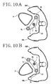
- FIG. 10A shows the state in which the handlebar 10 is turned to the right
- Fig. 10B shows the state in which the handlebar 10 is turned to the left.
- the front fender 9 may be positioned above the under bracket 8.
- the front fender 9 may be disposed so as to surround the surrounding area of the under bracket 8 without vertically overlapping the under bracket 8.
- the front cover 2 comprises the center cover 30, side covers 60L and 60R, a rear cover 80 (see Fig. 7 ), and an inner fender 81 (see Fig. 9 ).
- the center cover 30, the left side cover 60L, and the right side cover 60R are separate parts that are assembled together. They may also be provided for integral in other embodiments.
- the center cover 30 is disposed in front of the head pipe 6A.
- the side covers 60L and 60R are joined to the center cover 30.
- the rear cover 80 is positioned at the rear of the head pipe 6A.
- the rear cover 80 is joined to the center cover 30 and the side covers 60L and 60R.
- the front cover 2 of the present embodiment corresponds to the "front cover portion" of the present invention.
- the headlight opening 40 is formed in a vehicle-widthwise center and vertically lower area of the center cover 30.
- the headlight opening 40 is formed in an elliptical shape whose vertical length is longer than its lateral length.
- the number of the headlight opening 40 formed in the center cover 30 is one.
- the lateral length of the headlight opening 40 is set at about 1/2 of the maximum lateral length of the center cover 30.
- the vertical length of the headlight opening 40 is set at about 1/2 of the maximum vertical length of the center cover 30.
- the headlight opening 40 is formed in a relatively large size in the present embodiment.
- a headlight 45 is disposed in the headlight opening 40.
- the headlight 45 includes a housing 82, a valve 42, and a lens 43.
- the lens 43 which covers an outward area of the valve 42, is fitted in the headlight opening 40.
- the lens 43, as well as the center cover 30, slopes down forward, as viewed from a side of the vehicle.
- the lens 43 protrudes forward from the center cover 30.
- a top end 40t of the headlight 45 also protrudes forward from the center cover 30.
- the center cover 30 has one or more horn holes 41 formed therein.
- the horn holes 41 are formed in an upper right portion of the center cover 30 as viewed from the front.
- the number of the horn holes 41 provided is two.
- Each of the horn holes 41 is formed in substantially an elliptical shape as viewed from the front.
- the horn holes 41 are arranged so as to be lined up vertically.
- the horn holes 41 are formed at positions higher than the headlight opening 40.
- a horn 12 is disposed at the rear of the horn holes 41.
- valley lines 32 and the portions outside the valley lines 32 are formed so that their surface slopes are different from each other. It is possible to form ridge lines in place of the valley lines 32.
- valley line refers to a line formed by a continuous line-like portion that is recessed from both sides thereof.
- ridge line refers to a line formed by a continuous line-like portion that protrudes from both sides thereof.
- the front cover 2 forms a contour such as to be recessed inward at boundary portions 50 between the center cover 30 and the side covers 60L and 60R, as viewed from the front.
- Each of the boundary portions 50 includes the bottom outer end portion 30A that is a boundary portion of the center cover 30 from the side cover 60L or 60R, and a top end portion 60A that is a boundary portion of each of the side covers 60L and 60R from the center cover 30.
- the portion of the bottom outer end portion 30A of the center cover 30 that is upward of a top end 35t, i.e., the top outer end portion 30B, is formed in such a shape that its width becomes narrower and narrower toward the top, as viewed from the front.
- the bottom outer end portion 30A of the center cover 30 that is lower than the top end 35t is formed in such a shape that its widths becomes narrower and narrower toward the bottom, as viewed from the front.
- the bottom outer end portion 30A is formed so as to extend obliquely in a front-rear direction in a side portion of the center cover 30. This ensures a long junction portion between the center cover 30 and the side covers 60L and 60R, resulting in a sufficient strength of the junction portion, and prevents those components from increasing in their sizes vehicle-widthwise.
- the left side cover 60L and the right side cover 60R extend respectively from the left and right of the center cover 30, as viewed from the front, in a substantially downward direction toward the sides of the front wheel 3.
- the top end portions 60A of the side covers 60L and 60R are joined to the bottom outer end portions 30A of the center cover 30.
- the side covers 60L and 60R are separate parts from the center cover 30, and they extend from the inner side ends (the line connecting the top end 35t and a bottom end 35b shown in Fig. 1 ) of the top end portions 60A, as viewed from the front.
- the term "an end portion of the cover” refers to an end of the portion that can be seen from the outside. For example, when two covers are joined to each other at a junction portion and one of the covers is placed below the other cover, the end portion of the one cover refers to the junction portion, not the portion that is placed under the other cover.
- Each of the side covers 60L and 60R has a bulging portion 61 that extends further vehicle-widthwise outward of each of the bottom outer end portions 30A of the center cover 30. At least a portion of the bulging portion 61 is positioned at the same level as that of the bottom outer end portions 30A of the center cover 30. The bulging portion 61 is positioned at about the same level as that of the under bracket 8. The bulging portion 61 is formed at least from vertically at about the same level as the bottom outer end portions 30A of the center cover 30 to about the same level as the under bracket 8. The bulging portion 61 bulges toward the outside.
- the term “outside” here means, of the outer surfaces side and the inner surface sides of the side covers 60L and 60R, the outer surface sides thereof. More specifically, the “outside” means the side that is exposed externally.
- the bulging portion 61 is a part that is positioned outward of the bottom outer end portions 30A of the center cover 30 and that bulges vehicle-widthwise outwardly with respect to a virtual curved surface joining the center cover 30 to the side covers 60L and 60 R seamlessly and smoothly.
- the side covers 60L and 60R slope down rearward in such a manner as to be directed more rearward toward the bottom side.
- each of the bulging portions 61 is formed at the portion of each of the side covers 60L and 60R at which the front-to-rear length thereof is the greatest.
- a flasher opening 62 is formed in each of the side covers 60L and 60R.
- the flasher opening 62 is formed in each of the bulging portions 61.
- the flasher opening 62 is formed near the top end portion 60A. In other words, the flasher opening 62 is formed near the bottom outer end portion 30A of the center cover 30.
- the flasher opening 62 is formed in a substantially triangular shape pointing toward the front in the present embodiment, but the shape of the flasher opening 62 is not particularly limited.
- a side 62a of the flasher opening 62 that is positioned vehicle-widthwise inward extends obliquely in a rearward and upward direction.
- the side 62a is substantially parallel to the contour of the bottom outer end portion 30A.
- each of the lenses 64 is positioned vehicle-widthwise outward of each of the side covers 60L and 60R at a predetermined location that is along a front-rear direction, as viewed in plan. That is, at least a portion of the lens 64 protrudes from the side cover 60L or 60R at the predetermined location that is along a front-rear direction.
- the side cover 60L has a bent portion 60k that is bent vehicle-widthwise inwardly (i.e., to the left in Fig. 11A ) from the top end portion 60A.
- the bottom outer end portion 30A of the center cover 30 has a protruding piece 30k extending obliquely in a downward direction.
- the center cover 30 and the side cover 60L are assembled together so that the protruding piece 30k abuts onto the bent portion 60k.
- the protruding piece 30k may be disposed in such a manner as to be displaced inwardly with respect to the bent portion 60k.
- Reference numeral L2 indicates the amount of displacement.
- the right side cover 60R and the center cover 30 are assembled in a like manner.
- the positional relationship between the headlight opening 40 and each of the flasher openings 62 will be described. Note that the lens 43 is fitted in the headlight opening 40, and the lenses 64 are fitted in the flasher openings 62. Accordingly, the positional relationship between the headlight opening 40 and each of the flasher openings 62 is substantially the same as that between the lens 43 and each of the lenses 64.
- a vehicle-widthwise outside end 40o of the headlight opening 40 is positioned inward of a vehicle-widthwise inside end 62i of the flasher opening 62, as viewed from the front.
- the headlight opening 40 and each of the flasher openings 62 partially overlap with each other.
- at least a portion of each flasher opening 62 is positioned at a position that is lower than the top end 40t of the headlight opening 40 but higher than a bottom end 40b thereof, as viewed from the front.
- the position of a top end 62t of each flasher opening 62 is lower than the top end 40t of the headlight opening 40.
- the top end 40t of the headlight opening 40 matches a rear end 40r of the headlight opening 40.
- the rear end 40r of the headlight opening 40 is positioned slightly rearward of a front end 62f of the flasher opening 62.
- a center 62c of the flasher opening 62 is positioned rearward of the rear end 40r of the headlight opening 40.
- the headlight opening 40 is arranged at a position higher than the under bracket 8, as viewed from the front.
- the bottom end 40b of the headlight opening 40 is positioned frontward of the under bracket 8. Since a part of the headlight 45 is positioned closer to the under bracket 8 side than the headlight opening 40, it is necessary to provide a certain space for accommodating the headlight 45 and cables connected to the headlight 45. However, since the bulging portion 30f is provided in the surrounding area of the headlight opening 40, such a space can be provided easily even when the center cover 30 is not disposed more frontward. As a result, the size of at least the center cover with respect to a front-rear direction can be made compact as a whole.
- each flasher 65 since a part of each flasher 65 is positioned closer to the under bracket 8 side than the flasher opening 62, it is necessary to provide a certain space for accommodating the valve 63 and cables connected to the valve 63. However, since the bulging portion 61 is provided in the surrounding area of each flasher opening 62, such a space can be provided easily. As a result, the size of at least the side covers 60L and 60R with respect to a vehicle-width direction can be made compact as a whole.
- each of the valves 63 is disposed upward of the under bracket 8. Also as illustrated in Figs. 6 and 8 , each of the valves 63 is disposed frontward of the head pipe 6A.
- the bulging portions 61 of the side covers 60L and 60R are positioned at the same level as that of the under bracket 8.
- the motor scooter 1 is capable of preventing the front cover 2 from becoming large in size while ensuring a sufficient mudguard function, because it has what is called the movable type front fender 9.
- the front portion of the vehicle can be made compact in size.
- the surrounding portion of the handlebar 10 can be made more compact in size in comparison with the case in which they are arranged in a surrounding area of the handlebar 10, because the headlight 45 and the flashers 65 are disposed in the front cover 2.
- the scooter type vehicle has an under bracket that joins a lower part of the steering shaft and upper parts of the left and right fork pipes.
- the under bracket When the rider turns the handlebar, the under bracket is turned via the steering shaft.
- the under bracket has a certain width with respect to a vehicle-width direction. For this reason, in order to turn the under bracket without causing the under bracket to make contact with the front cover, it is necessary to provide a certain gap between the under bracket and the front cover.
- the flashers when the flashers are to be disposed in a lower portion of the front cover at the same level as that of the under bracket, it is necessary that the flashers be disposed vehicle-widthwise outward of the clearance space for the under bracket. As a consequence, the size of the front cover with respect to a vehicle-width direction becomes large, causing the front portion of the vehicle to become large.
- the flashers may appear possible to dispose the flashers, within the front cover, downward of the headlight and upward of the under bracket. In this case, however, it is necessary to provide a gap between the left and right flashers, so the front cover becomes large with respect to a vehicle-width direction. As a consequence, the front portion of the vehicle becomes large.
- the bulging portions 61 are formed at the positions in the side covers 60L and 60R that are at about the same level as that of the under bracket 8, in order to provide a clearance space for the under bracket 8.
- the flasher openings 62 are formed in the bulging portions 61.
- the flashers 65 are disposed in the bulging portions 61 so that the valves 63 (lamps, light bulbs, or other light sources) are disposed at the positions higher than the under bracket 8.
- the bulging portions 61 are formed at the positions of the side covers 60L and 60R that are at about the same level as that of the under bracket 8, the positions that need to be widest, and the flasher openings 62 are provided in the bulging portions 61 therein. Therefore, a sufficiently large gap L1 (see Fig. 1 ) can be provided between the headlight opening 40 and each flasher opening 62 without increasing the size of the front cover 2 as a whole, so high visibility of the flashers 65 can be ensured. Moreover, since the bulging portions 61 are formed only in the side covers 60L and 60R, the front cover 2 does not stick out vehicle-widthwise. Thus, the front cover 2 can be made compact in size.
- the motor scooter 1 allows the front portion of the vehicle to be compact in size while ensuring high visibility of the flashers and a sufficient mudguard function.
- the headlight opening 40 is arranged at a position higher than the under bracket 8, as viewed from the front. This allows the headlight 45 to be disposed relatively rearwardly (see Fig. 6 ). As a result, the front cover 2 sticks out less frontward, allowing the front cover 2 to be compact in size.
- valve 63 of each flasher 65 is disposed upward of the under bracket 8, as illustrated in Fig. 6 .
- This allows the valve 63 and the under bracket 8 not to make contact with each other even when the valve 63 is disposed relatively vehicle-widthwise inwardly. As a result, size reduction of the front cover 2 is facilitated.
- the under bracket 8 is not likely to be an obstacle during maintenance, for example, replacement of the valve 63. Therefore, maintenance of the valve 63 is easy.
- the portion of the center cover 30 that is in front of the under bracket 8 is disposed relatively frontward.
- the front portion of the center cover 30 by disposing the headlight 45 at a relatively low position can be utilized effectively as a space for accommodating the headlight 45. This serves to make the frontward protrusion of the headlight 45 less noticeable.
- the top end 62t of the flasher opening 62 is positioned upward of the bottom end 40b of the headlight opening 40.
- the top end of the flasher 65 is positioned upward of the bottom end of the headlight 45. Since the headlight 45 is disposed at a relatively low position in this way, the front portion of the vehicle can be made compact in size.
- the bottom end 40b of the headlight opening 40 is positioned upward of the bottom end 62b of the flasher opening 62.
- the bottom end of the headlight 45 is positioned upward of the bottom end of the flasher 45.
- a vehicle-widthwise outside end 40o of the headlight opening 40 is positioned inward of a vehicle-widthwise inside end 62i of the flasher opening 62, as viewed from the front.
- the front-to-rear length F1 of each flasher 65 is set longer than the left-to-right length F2 thereof. Therefore, the front cover 2 can be made compact in size along a left-right direction while ensuring a sufficient size of the flashers 65.
- a rear end 45r of the headlight 45 is positioned rearward of a front end 8f of the under bracket 8. This means that the amount of frontward protrusion of the headlight 45 is small. As a result, the front portion of the vehicle can be made compact in size.
- the front end 8f of the under bracket 8 is positioned rearward of the front end 65f of each flasher 65 and frontward of the rear end 65r of each flasher 65.
- the front-to-rear length of the side covers 60L and 60R can be made shorter than in the case that the entire flasher 65 is disposed frontward of, or rearward of, the under bracket 8.
- the front end 8f of the under bracket 8 is positioned frontward of the rear end of the lens 64. Therefore, the front-to-rear length of the side covers 60L and 60R can be made shorter than in the case that the entire under bracket 8 is positioned rearward of the rear end of the lens 64.
- the top end 35t of the junction portion of the center cover 30 to each of the side covers 60L and 60R is positioned downward of the top end 40t of the headlight opening 40 and upward of the bottom end 40b thereof, as viewed from the front. Since the top ends of the side covers 60L and 60R are disposed at low positions, the vertical length of the side covers 60L and 60R can be kept short.
- the bottom end 35b of the junction portion of the center cover 30 to each of the side covers 60L and 60R is positioned downward of the bottom end 40b of the headlight opening 40, as viewed from the front.
- the headlight 45 is positioned upward of the bottom end 35b.
- each of the flashers 65 is disposed at a position overlapping the head pipe 6A, as viewed from a side of the vehicle. Therefore, the front-to-rear length of the side covers 60L and 60R can be made shorter than in the case that the flashers 65 are disposed frontward of, or rearward of, the head pipe 6A.
- a vertically middle position of the headlight opening 40 is positioned at a position lower than a vertically middle position of the center cover 30 as viewed from the front; and at least a portion of the center cover 30 that is higher than the vertically middle position thereof is formed in such a shape that its width becomes narrower and narrower toward its top end, as viewed from the front.
- the upper portion of the center cover 30 is allowed to be compact in size, and as a result, the size of the front cover 2 can be kept small.
- center cover 30, the left side cover 60L, and the right side cover 60R may be formed integrally, they are separate parts in the present embodiment. Therefore, the center cover 30 can be kept small. Likewise, the side covers 60L and 60R can be kept small.
- the valve 63 of the flasher 65 is disposed frontward of the head pipe 6A.
- the head pipe 6A is not likely to be an obstacle during maintenance, for example, replacement of the valve 63. Therefore, maintenance of the valve 63 is easy.
- the lens 64 bulges toward the outside further from the bulging portion 61 of each of the side covers 60L and 60R.
- visibility of the flasher 65 can be further improved.
- this embodiment comprises a motor scooter 1 which has a front cover 2 having a center cover 30 and side covers 60L, 60R, and a movable type front fender 9.
- a headlight opening 40 is formed in the center cover 30.
- Each of the side covers 60L, 60R has a flasher opening 62.
- Each of the side covers 60L, 60R has bulging portions 61 each including a portion that is positioned, as viewed from the front, at substantially the same level as that of an under bracket 8 and vehicle-widthwise outward of a top end portion 60A.
- the flasher opening 62 is formed in the bulging portion 61 so that a valve of a flasher 65 is disposed at a position higher than the under bracket 8.
Landscapes
- Engineering & Computer Science (AREA)
- Mechanical Engineering (AREA)
- Automatic Cycles, And Cycles In General (AREA)
- Non-Portable Lighting Devices Or Systems Thereof (AREA)
- Lighting Device Outwards From Vehicle And Optical Signal (AREA)
Abstract
Description
- The present invention relates to scooter type vehicles.
-
JP 10-226374 A - A steering shaft is supported rotatably by a head pipe. A handlebar is secured to a top end portion of the steering shaft. A front fork is secured to a bottom end portion of the steering shaft. A front wheel is supported rotatably by a lower end portion of the front fork. The upper half portion of the front wheel is covered by a movable type front fender that turns together with the handlebar.
- The movable type front fender has the mudguard function to prevent the rider from being splashed with the mud thrown up by the front wheel. With the movable type front fender, it is possible to prevent the rider sufficiently from being splashed with mud even if the front cover is not particularly large. Thus, the above-described scooter type vehicle enables the front cover to be compact in size while ensuring a sufficient mudguard function. Moreover, the movable type front fender can turn together with the front wheel; therefore, unlike the stationary type front fender, it is not necessary to cover a wide area that surrounds the front wheel. As a result, the scooter type vehicle enables the front fender to be compact while ensuring a sufficient mudguard function.
- A scooter type vehicle in which a handle cover that is a separate part from the front cover is provided in front of the handlebar and a headlight or flashers is/are provided in the handle cover is known. In this scooter type vehicle, the handle cover tends to be large in size because the handle cover needs to have a space for installing the headlight or flashers. In the scooter type vehicle described in
JP 10-226374A JP 10-226374A - Nevertheless, in the scooter type vehicle described in
JP 10-226374A - It is an object of the present invention to provide a scooter type vehicle that enables a front portion of the vehicle to be compact in size while ensuring the visibility of the flashers and a sufficient mudguard function.
- The above objective, according to the present invention, is performed by a scooter type vehicle having the features of
claim 1. - The present invention allows a front portion of the vehicle to be compact in size while ensuring visibility of the flashers and a sufficient mudguard function.
Preferred embodiments are laid down in the further subclaims. -
-
Fig. 1 is a front view of a motor scooter; -
Fig. 2 is a left side view of a portion of the motor scooter; -
Fig. 3 is a left side view of a portion of the motor scooter; -
Fig. 4 is a plan view of a portion of the motor scooter; -
Fig. 5 is a plan view of the portion of the motor scooter on which flashers are not disposed; -
Fig. 6 is a left side view illustrating the internal structure of a portion of the motor scooter; -
Fig. 7 is a cross-sectional view taken along line VII-VII ofFig. 3 ; -
Fig. 8 is a cross-sectional view taken along line VIII-VIII ofFig. 3 ; -
Fig. 9 is a cross-sectional view taken along line IX-IX ofFig. 3 ; -
Fig. 10A is a cross-sectional view corresponding toFig. 9 , illustrating the state in which the handle bar is turned to the right, andFig. 10B is a cross-sectional view corresponding toFig. 9 , illustrating the state in which the handle bar is turned to the left; and -
Figs. 11A and 11B are cross-sectional views illustrating how the center cover and the side cover are fitted. - As illustrated in
Figs. 1 to 4 , amotor scooter 1 according to the present embodiment is furnished with acenter cover 30 and afront cover 2 having a pair of left and right side covers: 60L and 60R. It should be noted that the terms "front," "rear," "left," and "right" refer to front, rear, left, and right as defined based on the perspective of the rider of themotor scooter 1, respectively. - As illustrated in
Fig. 2 , themotor scooter 1 has abody frame 6. Thebody frame 6 has a thehead pipe 6A, adown frame portion 6B extending from thehead pipe 6A obliquely in a downward and rearward direction, and arear frame portion 6C extending from a bottom portion of thedown frame portion 6B in a rearward direction. Therear frame portion 6C is joined to thedown frame portion 6B by welding, for example. Afoot board 70 is provided above therear frame portion 6C. Thefoot board 70 is joined to a lower part of thefront cover 2. Thefront cover 2 and thefoot board 70 constitute avehicle body cover 90. Aseat 71 is provided obliquely above and at the rear of thefoot board 70. It should be noted thatFig. 2 is merely for illustrating thebody frame 6, and the specific shape of thefront cover 2 therein is different from that of the embodiment (i.e., that having a shape as illustrated inFig. 1 ). In addition, a later-describedflasher 65 and so forth are not depicted inFig. 2 . - As illustrated in
Fig. 1 , themotor scooter 1 is furnished with afront wheel 3 and afront fork 4 for supporting thefront wheel 3. Thefront fork 4 has a pair of left andright fork pipes Fig. 6 ) supported rotatably by thehead pipe 6A, an underbracket 8 for joining a lower end portion of thesteering shaft 7 to thefork pipes Fig. 9 , thesteering shaft 7 is supported at the center of the underbracket 8. Thefork pipes bracket 8 at which thesteering shaft 7 is supported. As illustrated inFig. 1 , what is called a movabletype front fender 9 is disposed above thefront wheel 3. Thefront fender 9 is one example of the "mudguard body" of the present invention. Thefront fender 9 is positioned below the underbracket 8. Thefront fender 9 is secured to the underbracket 8. Thefork pipes front fender 9 and extend obliquely in a rearward and upward direction. When the rider turns ahandlebar 10, the steeringshaft 7, thefork pipes bracket 8 turn accordingly, causing thefront wheel 3 to turn. Thefront fender 9 turns in association with the turning of thehandlebar 10. Thefront fender 9 turns together with the underbracket 8.Fig. 10A shows the state in which thehandlebar 10 is turned to the right, andFig. 10B shows the state in which thehandlebar 10 is turned to the left. Here, thefront fender 9 may be positioned above the underbracket 8. In addition, thefront fender 9 may be disposed so as to surround the surrounding area of theunder bracket 8 without vertically overlapping the underbracket 8. - As illustrated in
Fig. 6 , thehandlebar 10 is disposed on top of and at the rear of thehead pipe 6A. Ahandle cover 11 is provided for thehandlebar 10. Thehandle cover 11 covers at least a frontward area of thehandlebar 10. Thehandle cover 11 is formed of a separate part from thefront cover 2. - The
front cover 2 comprises thecenter cover 30, side covers 60L and 60R, a rear cover 80 (seeFig. 7 ), and an inner fender 81 (seeFig. 9 ). Thecenter cover 30, theleft side cover 60L, and theright side cover 60R are separate parts that are assembled together. They may also be provided for integral in other embodiments. Thecenter cover 30 is disposed in front of thehead pipe 6A. The side covers 60L and 60R are joined to thecenter cover 30. Therear cover 80 is positioned at the rear of thehead pipe 6A. Therear cover 80 is joined to thecenter cover 30 and the side covers 60L and 60R. Thefront cover 2 of the present embodiment corresponds to the "front cover portion" of the present invention. It should be noted that thefront cover 2 of the present embodiment is merely one illustrative example, and ones having a cover with a different, in particular subdivided, configuration are also within the scope of the present invention. For example, each of the side covers 60L and 60R may be divided vertically into two parts. In addition, therear cover 80 may comprise a plurality of covers. Thefoot board 70, preferably, is joined seamlessly to therear cover 80. - As illustrated in
Fig. 1 , thecenter cover 30 is disposed above thefront wheel 3 as viewed from the front. More specifically, thecenter cover 30 is disposed above thefront fender 9. As viewed from the front, thecenter cover 30 is disposed below ahandle cover 11. In the present embodiment, a lower end portion of thehandle cover 11 is placed inside thecenter cover 30. In other words, the lower end portion of thehandle cover 11 and the upper end portion of thecenter cover 30 overlap with each other vertically. It should be noted that the lower end portion of thehandle cover 11 may be positioned upward of the upper end portion of thecenter cover 30. In other words, the lower end portion of thehandle cover 11 and the upper end portion of thecenter cover 30 may not overlap with each other vertically. - As illustrated in
Fig. 3 , thecenter cover 30 slopes down forward, as viewed from a side of the vehicle. Theentire center cover 30 is curved so that its vehicle-widthwise outer side portions are positioned rearward of its vehicle-widthwise center portion. In other words, thecenter cover 30 is curved so as to surround a surrounding area of thehead pipe 6A (seeFig. 4 ). Thecenter cover 30 has a bulgingportion 30f bulging forward toward aheadlight opening 40. As illustrated inFig. 1 , thecenter cover 30 includes bottomouter end portions 30A each of which is formed in such a shape as to be closer and closer to the vehicle-widthwise center as its level lowers, as viewed from the front, and topouter end portions 30B each of which is positioned upward of the bottomouter end portions 30A and is formed in such a shape as to be closer and closer to the vehicle-widthwise center as its level rises, as viewed from the front. Each bottomouter end portion 30A is formed so that, as viewed from the front, its upper portion is positioned vehicle-widthwise outward of its lower portion. Each topouter end portion 30B is formed so that, as viewed from the front, its lower portion is positioned vehicle-widthwise outward of its upper portion. - As illustrated in
Fig. 1 , theheadlight opening 40 is formed in a vehicle-widthwise center and vertically lower area of thecenter cover 30. Theheadlight opening 40 is formed in an elliptical shape whose vertical length is longer than its lateral length. The number of theheadlight opening 40 formed in thecenter cover 30 is one. The lateral length of theheadlight opening 40 is set at about 1/2 of the maximum lateral length of thecenter cover 30. The vertical length of theheadlight opening 40 is set at about 1/2 of the maximum vertical length of thecenter cover 30. Thus, theheadlight opening 40 is formed in a relatively large size in the present embodiment. - As illustrated in
Fig. 7 , aheadlight 45 is disposed in theheadlight opening 40. Theheadlight 45 includes ahousing 82, avalve 42, and alens 43. Thelens 43, which covers an outward area of thevalve 42, is fitted in theheadlight opening 40. As illustrated inFig. 3 , thelens 43, as well as thecenter cover 30, slopes down forward, as viewed from a side of the vehicle. Thelens 43 protrudes forward from thecenter cover 30. Atop end 40t of theheadlight 45 also protrudes forward from thecenter cover 30. - As illustrated in
Fig. 1 , thecenter cover 30 has one or more horn holes 41 formed therein. The horn holes 41 are formed in an upper right portion of thecenter cover 30 as viewed from the front. In the present embodiment, the number of the horn holes 41 provided is two. Each of the horn holes 41 is formed in substantially an elliptical shape as viewed from the front. The horn holes 41 are arranged so as to be lined up vertically. The horn holes 41 are formed at positions higher than theheadlight opening 40. Ahorn 12 is disposed at the rear of the horn holes 41. - A
valley line 31 in a substantially V shape as viewed from the front, andvalley lines 32 extending vertically are formed in the front face side of thecenter cover 30. The valley lines 32 are positioned vehicle-widthwise outward of theheadlight opening 40. The valley lines 32 are formed in a lower portion of thecenter cover 30. The valley lines 32 are positioned more and more vehicle-widthwise outward toward the top, as viewed from the front. The valley lines 32 are provided on the left and on the right, respectively. Thecenter cover 30 comprises acentral portion 30C positioned between the left and right valley lines 32, andside portions central portion 30C and theside portions - As illustrated in
Fig. 1 , thefront cover 2 forms a contour such as to be recessed inward atboundary portions 50 between thecenter cover 30 and the side covers 60L and 60R, as viewed from the front. Each of theboundary portions 50 includes the bottomouter end portion 30A that is a boundary portion of thecenter cover 30 from theside cover top end portion 60A that is a boundary portion of each of the side covers 60L and 60R from thecenter cover 30. The portion of the bottomouter end portion 30A of thecenter cover 30 that is upward of atop end 35t, i.e., the topouter end portion 30B, is formed in such a shape that its width becomes narrower and narrower toward the top, as viewed from the front. Also, the bottomouter end portion 30A of thecenter cover 30 that is lower than thetop end 35t is formed in such a shape that its widths becomes narrower and narrower toward the bottom, as viewed from the front. The bottomouter end portion 30A is formed so as to extend obliquely in a front-rear direction in a side portion of thecenter cover 30. This ensures a long junction portion between thecenter cover 30 and the side covers 60L and 60R, resulting in a sufficient strength of the junction portion, and prevents those components from increasing in their sizes vehicle-widthwise. - As illustrated in
Fig. 1 , theleft side cover 60L and theright side cover 60R extend respectively from the left and right of thecenter cover 30, as viewed from the front, in a substantially downward direction toward the sides of thefront wheel 3. Thetop end portions 60A of the side covers 60L and 60R are joined to the bottomouter end portions 30A of thecenter cover 30. The side covers 60L and 60R are separate parts from thecenter cover 30, and they extend from the inner side ends (the line connecting thetop end 35t and abottom end 35b shown inFig. 1 ) of thetop end portions 60A, as viewed from the front. It should be noted that in the present specification, the term "an end portion of the cover" refers to an end of the portion that can be seen from the outside. For example, when two covers are joined to each other at a junction portion and one of the covers is placed below the other cover, the end portion of the one cover refers to the junction portion, not the portion that is placed under the other cover. - Each of the side covers 60L and 60R has a bulging
portion 61 that extends further vehicle-widthwise outward of each of the bottomouter end portions 30A of thecenter cover 30. At least a portion of the bulgingportion 61 is positioned at the same level as that of the bottomouter end portions 30A of thecenter cover 30. The bulgingportion 61 is positioned at about the same level as that of theunder bracket 8. The bulgingportion 61 is formed at least from vertically at about the same level as the bottomouter end portions 30A of thecenter cover 30 to about the same level as the underbracket 8. The bulgingportion 61 bulges toward the outside. It should be noted that the term "outside" here means, of the outer surfaces side and the inner surface sides of the side covers 60L and 60R, the outer surface sides thereof. More specifically, the "outside" means the side that is exposed externally. The bulgingportion 61 is a part that is positioned outward of the bottomouter end portions 30A of thecenter cover 30 and that bulges vehicle-widthwise outwardly with respect to a virtual curved surface joining thecenter cover 30 to the side covers 60L and 60 R seamlessly and smoothly. Because of the presence of the bulgingportion 61, the tangents of thecenter cover 30 and the side covers 60L and 60R do not match at the junction portion as viewed from the front, so a recess is formed between thecenter cover 30 and each of the side covers 60L and 60R. In other words, the valley lines are formed at the junction portions between thecenter cover 30 and the side covers 60L and 60R. As illustrated inFig. 4 , portions of the bulgingportions 61 are visible when viewed in plan, and theflashers 65 are disposed in the visible portions. - As illustrated in
Fig. 3 , the side covers 60L and 60R slope down rearward in such a manner as to be directed more rearward toward the bottom side. As viewed from a side of the vehicle, each of the bulgingportions 61 is formed at the portion of each of the side covers 60L and 60R at which the front-to-rear length thereof is the greatest. - A
flasher opening 62 is formed in each of the side covers 60L and 60R. Theflasher opening 62 is formed in each of the bulgingportions 61. Theflasher opening 62 is formed near thetop end portion 60A. In other words, theflasher opening 62 is formed near the bottomouter end portion 30A of thecenter cover 30. Theflasher opening 62 is formed in a substantially triangular shape pointing toward the front in the present embodiment, but the shape of theflasher opening 62 is not particularly limited. Aside 62a of theflasher opening 62 that is positioned vehicle-widthwise inward extends obliquely in a rearward and upward direction. Theside 62a is substantially parallel to the contour of the bottomouter end portion 30A. - As illustrated in
Fig. 8 ,valves 63 are disposed theflasher openings 62. In addition, alens 64 for covering an outward area of thevalve 63 is fitted in each of theflasher openings 62. The front-to-rear length F1 of theflasher 65 is set longer than the left-to-right length F2 thereof.
Fig. 4 is a plan view illustrating the state in which theflashers 65 are disposed in theflasher openings 62.Fig. 5 is a plan view illustrating the state in which theflashers 65 are not disposed in theflasher openings 62. As illustrated inFig. 4 , at least a portion of each of thelenses 64 is positioned vehicle-widthwise outward of each of the side covers 60L and 60R at a predetermined location that is along a front-rear direction, as viewed in plan. That is, at least a portion of thelens 64 protrudes from theside cover - As illustrated in
Fig. 11A , theside cover 60L has abent portion 60k that is bent vehicle-widthwise inwardly (i.e., to the left inFig. 11A ) from thetop end portion 60A. Meanwhile, the bottomouter end portion 30A of thecenter cover 30 has a protrudingpiece 30k extending obliquely in a downward direction. Thecenter cover 30 and theside cover 60L are assembled together so that the protrudingpiece 30k abuts onto thebent portion 60k. It should be noted that, as illustrated inFig. 11B , the protrudingpiece 30k may be disposed in such a manner as to be displaced inwardly with respect to thebent portion 60k. Reference numeral L2 indicates the amount of displacement. Although not shown in the drawing, theright side cover 60R and thecenter cover 30 are assembled in a like manner. - Next, the positional relationship between the
headlight opening 40 and each of theflasher openings 62 will be described. Note that thelens 43 is fitted in theheadlight opening 40, and thelenses 64 are fitted in theflasher openings 62. Accordingly, the positional relationship between theheadlight opening 40 and each of theflasher openings 62 is substantially the same as that between thelens 43 and each of thelenses 64. - As illustrated in
Fig. 1 , a vehicle-widthwise outside end 40o of theheadlight opening 40 is positioned inward of a vehicle-widthwise inside end 62i of theflasher opening 62, as viewed from the front. In other words, with respect to a vehicle-width direction, there is a gap L1 between theheadlight opening 40 and each of theflasher openings 62. With respect to a vertical direction, theheadlight opening 40 and each of theflasher openings 62 partially overlap with each other. In other words, at least a portion of each flasher opening 62 is positioned at a position that is lower than thetop end 40t of theheadlight opening 40 but higher than abottom end 40b thereof, as viewed from the front. In addition, the position of atop end 62t of each flasher opening 62 is lower than thetop end 40t of theheadlight opening 40. - As illustrated in
Fig. 3 , as viewed from a side of the vehicle, thetop end 40t of the headlight opening 40 matches arear end 40r of theheadlight opening 40. Therear end 40r of theheadlight opening 40 is positioned slightly rearward of afront end 62f of theflasher opening 62. As viewed from a side of the vehicle, acenter 62c of theflasher opening 62 is positioned rearward of therear end 40r of theheadlight opening 40. - Next, the positional relationship between the
headlight opening 40 and the underbracket 8 will be described. As illustrated inFig. 1 , theheadlight opening 40 is arranged at a position higher than theunder bracket 8, as viewed from the front. In addition, as illustrated inFig. 6 , thebottom end 40b of theheadlight opening 40 is positioned frontward of theunder bracket 8. Since a part of theheadlight 45 is positioned closer to the underbracket 8 side than theheadlight opening 40, it is necessary to provide a certain space for accommodating theheadlight 45 and cables connected to theheadlight 45. However, since the bulgingportion 30f is provided in the surrounding area of theheadlight opening 40, such a space can be provided easily even when thecenter cover 30 is not disposed more frontward. As a result, the size of at least the center cover with respect to a front-rear direction can be made compact as a whole. - Likewise, since a part of each
flasher 65 is positioned closer to the underbracket 8 side than theflasher opening 62, it is necessary to provide a certain space for accommodating thevalve 63 and cables connected to thevalve 63. However, since the bulgingportion 61 is provided in the surrounding area of eachflasher opening 62, such a space can be provided easily. As a result, the size of at least the side covers 60L and 60R with respect to a vehicle-width direction can be made compact as a whole. - As illustrated in
Figs. 6 and8 , each of thevalves 63 is disposed upward of theunder bracket 8. Also as illustrated inFigs. 6 and8 , each of thevalves 63 is disposed frontward of thehead pipe 6A. The bulgingportions 61 of the side covers 60L and 60R are positioned at the same level as that of theunder bracket 8.
The afore-described design of the components need not always be provided in combination but sometimes their single presence is sufficient to perform the objective of the present invention and to achieve the desired effects substantially. - As described above, the
motor scooter 1 according to the present embodiment is capable of preventing thefront cover 2 from becoming large in size while ensuring a sufficient mudguard function, because it has what is called the movable typefront fender 9. As a result, the front portion of the vehicle can be made compact in size. Moreover, the surrounding portion of thehandlebar 10 can be made more compact in size in comparison with the case in which they are arranged in a surrounding area of thehandlebar 10, because theheadlight 45 and theflashers 65 are disposed in thefront cover 2. - In the case that the headlight and the left and right flashers are arrayed in a line along a vehicle width direction as in the scooter type vehicle described in
JP 10-226374A - It may be conceivable to dispose the flashers in a lower part of the front cover. However, the scooter type vehicle has an under bracket that joins a lower part of the steering shaft and upper parts of the left and right fork pipes. When the rider turns the handlebar, the under bracket is turned via the steering shaft. The under bracket has a certain width with respect to a vehicle-width direction. For this reason, in order to turn the under bracket without causing the under bracket to make contact with the front cover, it is necessary to provide a certain gap between the under bracket and the front cover. Accordingly, when the flashers are to be disposed in a lower portion of the front cover at the same level as that of the under bracket, it is necessary that the flashers be disposed vehicle-widthwise outward of the clearance space for the under bracket. As a consequence, the size of the front cover with respect to a vehicle-width direction becomes large, causing the front portion of the vehicle to become large.
- On the other hand, it may appear possible to dispose the flashers frontward of the clearance space for the under bracket. In this case, however, the front cover bulges frontward greatly, causing the front portion of the vehicle to become large.
- Furthermore, it may appear possible to dispose the flashers, within the front cover, downward of the headlight and upward of the under bracket. In this case, however, it is necessary to provide a gap between the left and right flashers, so the front cover becomes large with respect to a vehicle-width direction. As a consequence, the front portion of the vehicle becomes large.
- In contrast, in the
motor scooter 1 according to the present embodiment, the bulgingportions 61 are formed at the positions in the side covers 60L and 60R that are at about the same level as that of theunder bracket 8, in order to provide a clearance space for the underbracket 8. Moreover, theflasher openings 62 are formed in the bulgingportions 61. Theflashers 65 are disposed in the bulgingportions 61 so that the valves 63 (lamps, light bulbs, or other light sources) are disposed at the positions higher than theunder bracket 8. In the present embodiment, the bulgingportions 61 are formed at the positions of the side covers 60L and 60R that are at about the same level as that of theunder bracket 8, the positions that need to be widest, and theflasher openings 62 are provided in the bulgingportions 61 therein. Therefore, a sufficiently large gap L1 (seeFig. 1 ) can be provided between theheadlight opening 40 and each flasher opening 62 without increasing the size of thefront cover 2 as a whole, so high visibility of theflashers 65 can be ensured. Moreover, since the bulgingportions 61 are formed only in the side covers 60L and 60R, thefront cover 2 does not stick out vehicle-widthwise. Thus, thefront cover 2 can be made compact in size. - As a result, the
motor scooter 1 allows the front portion of the vehicle to be compact in size while ensuring high visibility of the flashers and a sufficient mudguard function. - In addition, the
headlight opening 40 is arranged at a position higher than theunder bracket 8, as viewed from the front. This allows theheadlight 45 to be disposed relatively rearwardly (seeFig. 6 ). As a result, thefront cover 2 sticks out less frontward, allowing thefront cover 2 to be compact in size. - Moreover, in the present embodiment, the
valve 63 of eachflasher 65 is disposed upward of theunder bracket 8, as illustrated inFig. 6 . This allows thevalve 63 and the underbracket 8 not to make contact with each other even when thevalve 63 is disposed relatively vehicle-widthwise inwardly. As a result, size reduction of thefront cover 2 is facilitated. In addition, the underbracket 8 is not likely to be an obstacle during maintenance, for example, replacement of thevalve 63. Therefore, maintenance of thevalve 63 is easy. - In order to ensure the clearance space for the under
bracket 8, the portion of thecenter cover 30 that is in front of theunder bracket 8 is disposed relatively frontward. As a result, the front portion of thecenter cover 30 by disposing theheadlight 45 at a relatively low position can be utilized effectively as a space for accommodating theheadlight 45. This serves to make the frontward protrusion of theheadlight 45 less noticeable. As illustrated inFig. 1 , in themotor scooter 1, thetop end 62t of theflasher opening 62 is positioned upward of thebottom end 40b of theheadlight opening 40. In other words, the top end of theflasher 65 is positioned upward of the bottom end of theheadlight 45. Since theheadlight 45 is disposed at a relatively low position in this way, the front portion of the vehicle can be made compact in size. - As illustrated in
Fig. 1 , thebottom end 40b of theheadlight opening 40 is positioned upward of thebottom end 62b of theflasher opening 62. In other words, the bottom end of theheadlight 45 is positioned upward of the bottom end of theflasher 45. This means that there is a portion in which the position of theheadlight 45 and the position of eachflasher 65 do not overlap vertically. Therefore, sufficient visibility of theheadlight 45 and theflashers 65 can be ensured. As a result, the front portion of the vehicle can be made compact in size while ensuring the high visibility. - As illustrated in
Fig. 1 , a vehicle-widthwise outside end 40o of theheadlight opening 40 is positioned inward of a vehicle-widthwise inside end 62i of theflasher opening 62, as viewed from the front. This means that theheadlight 45 and theflashers 65 are spaced apart along a left-right direction. Therefore, sufficient visibility of theheadlight 45 and theflashers 65 can be ensured. - As illustrated in
Fig. 8 , the front-to-rear length F1 of eachflasher 65 is set longer than the left-to-right length F2 thereof. Therefore, thefront cover 2 can be made compact in size along a left-right direction while ensuring a sufficient size of theflashers 65. - As illustrated in
Fig. 6 , arear end 45r of theheadlight 45 is positioned rearward of afront end 8f of theunder bracket 8. This means that the amount of frontward protrusion of theheadlight 45 is small. As a result, the front portion of the vehicle can be made compact in size. - As illustrated in
Fig. 6 , thefront end 8f of theunder bracket 8 is positioned rearward of thefront end 65f of eachflasher 65 and frontward of therear end 65r of eachflasher 65. As a result, the front-to-rear length of the side covers 60L and 60R can be made shorter than in the case that theentire flasher 65 is disposed frontward of, or rearward of, the underbracket 8. - The
front end 8f of theunder bracket 8 is positioned frontward of the rear end of thelens 64. Therefore, the front-to-rear length of the side covers 60L and 60R can be made shorter than in the case that the entire underbracket 8 is positioned rearward of the rear end of thelens 64. - As illustrated in
Fig. 1 , thetop end 35t of the junction portion of thecenter cover 30 to each of the side covers 60L and 60R is positioned downward of thetop end 40t of theheadlight opening 40 and upward of thebottom end 40b thereof, as viewed from the front. Since the top ends of the side covers 60L and 60R are disposed at low positions, the vertical length of the side covers 60L and 60R can be kept short. - As illustrated in
Fig. 1 , thebottom end 35b of the junction portion of thecenter cover 30 to each of the side covers 60L and 60R is positioned downward of thebottom end 40b of theheadlight opening 40, as viewed from the front. In other words, theheadlight 45 is positioned upward of thebottom end 35b. As a result, the amount of frontward protrusion of theheadlight 45 can be kept small. - As illustrated in
Fig. 6 , each of theflashers 65 is disposed at a position overlapping thehead pipe 6A, as viewed from a side of the vehicle. Therefore, the front-to-rear length of the side covers 60L and 60R can be made shorter than in the case that theflashers 65 are disposed frontward of, or rearward of, thehead pipe 6A. - As illustrated in
Fig. 1 , a vertically middle position of theheadlight opening 40 is positioned at a position lower than a vertically middle position of thecenter cover 30 as viewed from the front; and at least a portion of thecenter cover 30 that is higher than the vertically middle position thereof is formed in such a shape that its width becomes narrower and narrower toward its top end, as viewed from the front. Thus, the upper portion of thecenter cover 30 is allowed to be compact in size, and as a result, the size of thefront cover 2 can be kept small. - It should be noted that although the
center cover 30, theleft side cover 60L, and theright side cover 60R may be formed integrally, they are separate parts in the present embodiment. Therefore, thecenter cover 30 can be kept small. Likewise, the side covers 60L and 60R can be kept small. - As illustrated in
Fig. 8 , thevalve 63 of theflasher 65 is disposed frontward of thehead pipe 6A. As a result, thehead pipe 6A is not likely to be an obstacle during maintenance, for example, replacement of thevalve 63. Therefore, maintenance of thevalve 63 is easy. - The bulging
portion 61 of each of the side covers 60L and 60R bulges toward an outside. As a result, visibility of theflasher 65 can be further improved. - In addition, as illustrated in
Fig. 4 , thelens 64 bulges toward the outside further from the bulgingportion 61 of each of the side covers 60L and 60R. Thus, visibility of theflasher 65 can be further improved. - As illustrated in
Fig. 1 , as viewed from the front, theflasher 65 is positioned vehicle-widthwise outward of the bottomouter end portion 30A of thecenter cover 30. Thereby, visibility of theflasher 65 can be improved.
Thus, this embodiment comprises amotor scooter 1 which has afront cover 2 having acenter cover 30 and side covers 60L, 60R, and a movable typefront fender 9. Aheadlight opening 40 is formed in thecenter cover 30. Each of the side covers 60L, 60R has aflasher opening 62. Each of the side covers 60L, 60R has bulgingportions 61 each including a portion that is positioned, as viewed from the front, at substantially the same level as that of an underbracket 8 and vehicle-widthwise outward of atop end portion 60A. Theflasher opening 62 is formed in the bulgingportion 61 so that a valve of aflasher 65 is disposed at a position higher than theunder bracket 8.
Only selected embodiments have been chosen to illustrate the present invention. To those skilled in the art, however, it will be apparent from the foregoing disclosure that various changes and modifications can be made herein without departing from the scope of the invention as defined in the appended claims. Furthermore, the foregoing description of the embodiments according to the present invention is provided for illustration only, and not for limiting the invention as defined by the appended claims and their equivalents.
Claims (14)
- A scooter type vehicle comprising:a front wheel (3);a head pipe (6A);a front fork (4) having fork pipes (5L, 5R) disposed on the left and right of the front wheel (3), a steering shaft (7) rotatably supported by the head pipe (6A), and an under bracket (8) for connecting the steering shaft (7) to the front fork (4) and turning together with the steering shaft (7);a vehicle body cover (90) having a front cover portion (2) covering the head pipe (6A), and a foot board portion (70), joined to the front cover portion (2);a mudguard body (9) positioned between the front wheel (3) and the vehicle body cover (90) and configured to turn together with the under bracket (8);a headlight (45) disposed in a headlight opening (40) formed in the front cover portion (2); andflashers (65) disposed in flasher openings (62) formed in the front cover portion (2) and positioned outward of the headlight (45) in a vehicle-widthwise direction, each of the flashers (65) having a valve (63),characterized in that the front cover portion (2) comprises:a center cover (30) positioned in front of the head pipe (6A), the center cover (30) having the headlight opening (40) formed at a position upward of the under bracket (8),a pair of left and right side covers (60L, 60R) positioned on respective sides of the front wheel (3), each of said side covers (60L, 60R) having a bulging portion (61) including a portion positioned at about the level of the under bracket (8),wherein said flasher openings (62) are formed in the bulging portions (61) so that the valves (63) are disposed at positions higher than that of the under bracket (8).
- The scooter type vehicle according to claim 1, wherein the under bracket (8) is adapted to connect a lower end portion of the steering shaft (7) to the fork pipes (5L,5R).
- The scooter type vehicle according to claims 1 or 2, wherein the center cover (30) having a bottom outer end portion (30a), an upper portion of which is positioned in a vehicle-widthwise direction outward of a lower portion thereof as viewed from the front, wherein, preferably a top end portion of the side covers (60L,60R) being joined to the bottom outer end portion (30A) of the center cover (30), wherein, preferably the bulging portion (61) including a portion positioned outwards of a top end portion (60A) of the side cover (60L,60R) when considering a vehicle-widthwise direction.
- The scooter type vehicle according to one of the preceding claims 1 to 3, wherein a top end (62t) of each of the flasher openings (62) is positioned upward of a bottom end (40b) of the headlight opening (40), and/or a bottom end (40b) of the headlight opening (40) is positioned upward of a bottom end (62b) of each of the flasher openings (62), while preferably a vehicle-widthwise outside end (40o) of the headlight opening (40) is positioned, as viewed from the front, inward of a vehicle-widthwise inside end (62i) of each of the flasher openings (62).
- The scooter type vehicle according to any of claims 1 to 4, wherein a top end of each of the flashers (65) is positioned upward of a bottom end of the headlight (45), and/or a bottom end of the headlight (45) is positioned upward of a bottom end of each of the flashers (65), while, preferably, a rear end (45r) of the headlight (45) is positioned rearward of a front end (8f) of the under bracket (8).
- The scooter type vehicle according to any of claims 1 to 5, wherein a front-to-rear length (F1) of each of the flashers (65) is longer than a left-to-right length (F2) thereof and/or a front end (8f) of the under bracket (8) is positioned rearward of a front end (65f) of each of the flashers (65) and frontward of a rear end (65c) of each of the flashers (65).
- The scooter type vehicle according to any of claims 1 to 6, wherein each of the flasher (65) has a lens (64) covering an outward area of the valve (63); and a front end (8f) of the under bracket (8) is positioned frontward of a rear end of the lens (64).
- The scooter type vehicle according to any of claims 1 to 7, wherein a top end (35t) of a junction portion of the center cover (30) to the side covers (60L, 60R) is positioned, as viewed from the front, downward of a top end (40t) of the headlight opening (40) and upward of a bottom end (40b) thereof, and/or a bottom end (35b) of a junction portion of the center cover (30) to the side covers (60L, 60R) is positioned, as viewed from the front, downward of the bottom end (40b) of the headlight opening (40).
- The scooter type vehicle according to any of claims 1 to 8, wherein each of the flashers (65) is disposed at a position overlapping the head pipe (6A), as viewed from a side of the vehicle.
- The scooter type vehicle according to any of claims 1 to 9, wherein a vertically middle position of the headlight opening (40) is positioned at a position lower than a vertically middle position of the center cover (30) as viewed from the front; and, preferably, at least a portion of the center cover (30) that is higher than the vertically middle position thereof is formed in such a shape that its width becomes narrower and narrower toward its top end, as viewed from the front.
- The scooter type vehicle according to any of claims 1 to 10, wherein the left side cover (60L) and the right side cover (60R) are separate parts.
- The scooter type vehicle according to any of claims 1 to 11, wherein the bulging portion (61) of each of the side covers (60L, 60R) bulges toward an outside, and/or comprising a lens (64) covering an outward area of the valve (63) of each of the flashers (65); and wherein the lens (64) bulges toward the outside further from the bulging portion (61) of each of the side covers (60L, 60R).
- The scooter type vehicle according to any of claims 1 to 12, wherein each of the flashers (65) is positioned vehicle-widthwise outward of a bottom outer end portion (30A) of the center cover (30), as viewed from the front.
- The scooter type vehicle according to any of claims 1 to 13, wherein a rear end of the headlight (45) is positioned rearward of a front end (8f) of the under bracket, while, preferably, a front end of the under bracket (8) is positioned rearward of the front end (65f) of each flasher (65) and frontward of the rear end (65r) of each flasher (65) and/or a front end (8f) of the under bracket (8) is positioned frontward of the rear end of the lens (64) of the flasher (65).
Applications Claiming Priority (2)
| Application Number | Priority Date | Filing Date | Title |
|---|---|---|---|
| JP2008272845 | 2008-10-23 | ||
| JP2009235907A JP2010120629A (en) | 2008-10-23 | 2009-10-13 | Scooter type vehicle |
Publications (2)
| Publication Number | Publication Date |
|---|---|
| EP2179912A1 true EP2179912A1 (en) | 2010-04-28 |
| EP2179912B1 EP2179912B1 (en) | 2014-01-01 |
Family
ID=41665540
Family Applications (1)
| Application Number | Title | Priority Date | Filing Date |
|---|---|---|---|
| EP09013058.4A Not-in-force EP2179912B1 (en) | 2008-10-23 | 2009-10-15 | Scooter type vehicle |
Country Status (5)
| Country | Link |
|---|---|
| EP (1) | EP2179912B1 (en) |
| JP (1) | JP2010120629A (en) |
| CN (1) | CN101723029B (en) |
| ES (1) | ES2441811T3 (en) |
| TW (1) | TWI385097B (en) |
Cited By (3)
| Publication number | Priority date | Publication date | Assignee | Title |
|---|---|---|---|---|
| EP2669160A1 (en) * | 2012-05-28 | 2013-12-04 | Yamaha Hatsudoki Kabushiki Kaisha | Straddle type vehicle |
| EP2394893A3 (en) * | 2010-06-11 | 2014-11-05 | Yamaha Hatsudoki Kabushiki Kaisha | Saddle-ride type vehicle |
| EP2644484A3 (en) * | 2012-03-30 | 2014-12-17 | Yamaha Hatsudoki Kabushiki Kaisha | Straddle-type type vehicle |
Families Citing this family (6)
| Publication number | Priority date | Publication date | Assignee | Title |
|---|---|---|---|---|
| JP5564378B2 (en) * | 2010-09-24 | 2014-07-30 | 本田技研工業株式会社 | Vehicle lighter support structure |
| JP2013227005A (en) | 2012-03-27 | 2013-11-07 | Yamaha Motor Co Ltd | Straddle-type vehicle |
| CN104554557B (en) * | 2013-10-22 | 2017-11-17 | 雅马哈发动机株式会社 | Straddle type vehicle |
| JP6122413B2 (en) * | 2014-09-30 | 2017-04-26 | 本田技研工業株式会社 | Front structure of saddle-ride type vehicle |
| CN105172950B (en) * | 2015-08-14 | 2017-11-03 | 薛建南 | Electric car front panel assembly |
| CN113525566B (en) * | 2020-04-21 | 2022-06-07 | 雅马哈发动机株式会社 | Saddle-ride type vehicle |
Citations (6)
| Publication number | Priority date | Publication date | Assignee | Title |
|---|---|---|---|---|
| JPH08301171A (en) * | 1995-04-30 | 1996-11-19 | Yamaha Motor Co Ltd | Scooter body cover structure |
| JPH10226374A (en) | 1997-02-13 | 1998-08-25 | Yamaha Motor Co Ltd | Scooter type motorcycle |
| EP0953500A2 (en) | 1998-04-27 | 1999-11-03 | Yamaha Hatsudoki Kabushiki Kaisha | Grab handle arrangement for scooter type vehicle |
| JP2002068058A (en) * | 2001-07-19 | 2002-03-08 | Yamaha Motor Co Ltd | Motorcycle |
| EP2017168A1 (en) * | 2007-07-19 | 2009-01-21 | Yamaha Hatsudoki Kabushiki Kaisha | Straddle type vehicle |
| EP2028413A2 (en) * | 2007-08-22 | 2009-02-25 | Yamaha Hatsudoki Kabushiki Kaisha | Headlight device and vehicle |
Family Cites Families (4)
| Publication number | Priority date | Publication date | Assignee | Title |
|---|---|---|---|---|
| TW369494B (en) * | 1996-03-19 | 1999-09-11 | Honda Motor Co Ltd | Scooter shell structure |
| TW593046B (en) * | 2001-02-09 | 2004-06-21 | Honda Motor Co Ltd | Motor-scooter type vehicle body cover structure |
| CN2799378Y (en) * | 2005-06-20 | 2006-07-26 | 三阳工业股份有限公司 | locomotive structure |
| CN2837179Y (en) * | 2005-09-23 | 2006-11-15 | 重庆宗申技术开发研究有限公司 | Electric bicycle |
-
2009
- 2009-10-13 JP JP2009235907A patent/JP2010120629A/en active Pending
- 2009-10-15 EP EP09013058.4A patent/EP2179912B1/en not_active Not-in-force
- 2009-10-15 ES ES09013058.4T patent/ES2441811T3/en active Active
- 2009-10-16 TW TW098135177A patent/TWI385097B/en active
- 2009-10-23 CN CN2009102053924A patent/CN101723029B/en active Active
Patent Citations (6)
| Publication number | Priority date | Publication date | Assignee | Title |
|---|---|---|---|---|
| JPH08301171A (en) * | 1995-04-30 | 1996-11-19 | Yamaha Motor Co Ltd | Scooter body cover structure |
| JPH10226374A (en) | 1997-02-13 | 1998-08-25 | Yamaha Motor Co Ltd | Scooter type motorcycle |
| EP0953500A2 (en) | 1998-04-27 | 1999-11-03 | Yamaha Hatsudoki Kabushiki Kaisha | Grab handle arrangement for scooter type vehicle |
| JP2002068058A (en) * | 2001-07-19 | 2002-03-08 | Yamaha Motor Co Ltd | Motorcycle |
| EP2017168A1 (en) * | 2007-07-19 | 2009-01-21 | Yamaha Hatsudoki Kabushiki Kaisha | Straddle type vehicle |
| EP2028413A2 (en) * | 2007-08-22 | 2009-02-25 | Yamaha Hatsudoki Kabushiki Kaisha | Headlight device and vehicle |
Cited By (3)
| Publication number | Priority date | Publication date | Assignee | Title |
|---|---|---|---|---|
| EP2394893A3 (en) * | 2010-06-11 | 2014-11-05 | Yamaha Hatsudoki Kabushiki Kaisha | Saddle-ride type vehicle |
| EP2644484A3 (en) * | 2012-03-30 | 2014-12-17 | Yamaha Hatsudoki Kabushiki Kaisha | Straddle-type type vehicle |
| EP2669160A1 (en) * | 2012-05-28 | 2013-12-04 | Yamaha Hatsudoki Kabushiki Kaisha | Straddle type vehicle |
Also Published As
| Publication number | Publication date |
|---|---|
| TW201026548A (en) | 2010-07-16 |
| CN101723029A (en) | 2010-06-09 |
| JP2010120629A (en) | 2010-06-03 |
| CN101723029B (en) | 2012-07-25 |
| ES2441811T3 (en) | 2014-02-06 |
| TWI385097B (en) | 2013-02-11 |
| EP2179912B1 (en) | 2014-01-01 |
Similar Documents
| Publication | Publication Date | Title |
|---|---|---|
| EP2179912B1 (en) | Scooter type vehicle | |
| EP2258611B1 (en) | Scooter-type vehicle | |
| US7635140B2 (en) | Fender structure for motorcycle | |
| US20060087144A1 (en) | Front cowl and vehicle provided with the same | |
| US20080158896A1 (en) | Straddle-Type Vehicle | |
| JP2013112295A (en) | Straddle type vehicle | |
| JP2009166790A (en) | Flasher and saddle-ride type vehicles | |
| JP2012017087A (en) | Saddle-ride type vehicle | |
| EP2644485B1 (en) | Saddle-ride type vehicle | |
| EP2871121B1 (en) | Saddle riding type vehicle | |
| EP3251925B1 (en) | Straddle-type vehicle | |
| EP2221206B1 (en) | Scooter type vehicle | |
| EP2644488B1 (en) | Saddle-ride type vehicle | |
| JP2018001812A (en) | Saddle-riding type vehicle | |
| EP2163464A1 (en) | Saddle-type vehicle | |
| EP2463575B1 (en) | Lighting device and two-wheeled motor vehicle | |
| JP6356627B2 (en) | A saddle-ride type vehicle equipped with a blinker | |
| CN109305261B (en) | Saddle-ride type vehicle | |
| JP2020066408A (en) | Saddle-riding type vehicle | |
| EP3305642B1 (en) | Straddled vehicle | |
| EP2610150B1 (en) | Saddle-ride type vehicle | |
| JP2013112272A (en) | Straddle type vehicle | |
| JP2010100155A (en) | Scooter | |
| EP3305639B1 (en) | Straddled vehicle | |
| JP7472178B2 (en) | Saddle type vehicle |
Legal Events
| Date | Code | Title | Description |
|---|---|---|---|
| PUAI | Public reference made under article 153(3) epc to a published international application that has entered the european phase |
Free format text: ORIGINAL CODE: 0009012 |
|
| AK | Designated contracting states |
Kind code of ref document: A1 Designated state(s): AT BE BG CH CY CZ DE DK EE ES FI FR GB GR HR HU IE IS IT LI LT LU LV MC MK MT NL NO PL PT RO SE SI SK SM TR |
|
| AX | Request for extension of the european patent |
Extension state: AL BA RS |
|
| 17P | Request for examination filed |
Effective date: 20101027 |
|
| 17Q | First examination report despatched |
Effective date: 20110310 |
|
| GRAP | Despatch of communication of intention to grant a patent |
Free format text: ORIGINAL CODE: EPIDOSNIGR1 |
|
| INTG | Intention to grant announced |
Effective date: 20130821 |
|
| GRAS | Grant fee paid |
Free format text: ORIGINAL CODE: EPIDOSNIGR3 |
|
| GRAA | (expected) grant |
Free format text: ORIGINAL CODE: 0009210 |
|
| AK | Designated contracting states |
Kind code of ref document: B1 Designated state(s): AT BE BG CH CY CZ DE DK EE ES FI FR GB GR HR HU IE IS IT LI LT LU LV MC MK MT NL NO PL PT RO SE SI SK SM TR |
|
| REG | Reference to a national code |
Ref country code: GB Ref legal event code: FG4D |
|
| REG | Reference to a national code |
Ref country code: CH Ref legal event code: EP |
|
| REG | Reference to a national code |
Ref country code: IE Ref legal event code: FG4D |
|
| REG | Reference to a national code |
Ref country code: ES Ref legal event code: FG2A Ref document number: 2441811 Country of ref document: ES Kind code of ref document: T3 Effective date: 20140206 |
|
| REG | Reference to a national code |
Ref country code: DE Ref legal event code: R096 Ref document number: 602009021094 Country of ref document: DE Effective date: 20140213 |
|
| REG | Reference to a national code |
Ref country code: AT Ref legal event code: REF Ref document number: 647474 Country of ref document: AT Kind code of ref document: T Effective date: 20140215 |
|
| REG | Reference to a national code |
Ref country code: NL Ref legal event code: VDEP Effective date: 20140101 |
|
| REG | Reference to a national code |
Ref country code: AT Ref legal event code: MK05 Ref document number: 647474 Country of ref document: AT Kind code of ref document: T Effective date: 20140101 |
|
| REG | Reference to a national code |
Ref country code: LT Ref legal event code: MG4D |
|
| PG25 | Lapsed in a contracting state [announced via postgrant information from national office to epo] |
Ref country code: IS Free format text: LAPSE BECAUSE OF FAILURE TO SUBMIT A TRANSLATION OF THE DESCRIPTION OR TO PAY THE FEE WITHIN THE PRESCRIBED TIME-LIMIT Effective date: 20140501 Ref country code: LT Free format text: LAPSE BECAUSE OF FAILURE TO SUBMIT A TRANSLATION OF THE DESCRIPTION OR TO PAY THE FEE WITHIN THE PRESCRIBED TIME-LIMIT Effective date: 20140101 |
|
| PG25 | Lapsed in a contracting state [announced via postgrant information from national office to epo] |
Ref country code: CY Free format text: LAPSE BECAUSE OF FAILURE TO SUBMIT A TRANSLATION OF THE DESCRIPTION OR TO PAY THE FEE WITHIN THE PRESCRIBED TIME-LIMIT Effective date: 20140101 Ref country code: PT Free format text: LAPSE BECAUSE OF FAILURE TO SUBMIT A TRANSLATION OF THE DESCRIPTION OR TO PAY THE FEE WITHIN THE PRESCRIBED TIME-LIMIT Effective date: 20140502 Ref country code: SE Free format text: LAPSE BECAUSE OF FAILURE TO SUBMIT A TRANSLATION OF THE DESCRIPTION OR TO PAY THE FEE WITHIN THE PRESCRIBED TIME-LIMIT Effective date: 20140101 Ref country code: AT Free format text: LAPSE BECAUSE OF FAILURE TO SUBMIT A TRANSLATION OF THE DESCRIPTION OR TO PAY THE FEE WITHIN THE PRESCRIBED TIME-LIMIT Effective date: 20140101 Ref country code: FI Free format text: LAPSE BECAUSE OF FAILURE TO SUBMIT A TRANSLATION OF THE DESCRIPTION OR TO PAY THE FEE WITHIN THE PRESCRIBED TIME-LIMIT Effective date: 20140101 Ref country code: NL Free format text: LAPSE BECAUSE OF FAILURE TO SUBMIT A TRANSLATION OF THE DESCRIPTION OR TO PAY THE FEE WITHIN THE PRESCRIBED TIME-LIMIT Effective date: 20140101 |
|
| PG25 | Lapsed in a contracting state [announced via postgrant information from national office to epo] |
Ref country code: HR Free format text: LAPSE BECAUSE OF FAILURE TO SUBMIT A TRANSLATION OF THE DESCRIPTION OR TO PAY THE FEE WITHIN THE PRESCRIBED TIME-LIMIT Effective date: 20140101 Ref country code: LV Free format text: LAPSE BECAUSE OF FAILURE TO SUBMIT A TRANSLATION OF THE DESCRIPTION OR TO PAY THE FEE WITHIN THE PRESCRIBED TIME-LIMIT Effective date: 20140101 Ref country code: BE Free format text: LAPSE BECAUSE OF FAILURE TO SUBMIT A TRANSLATION OF THE DESCRIPTION OR TO PAY THE FEE WITHIN THE PRESCRIBED TIME-LIMIT Effective date: 20140101 |
|
| REG | Reference to a national code |
Ref country code: DE Ref legal event code: R097 Ref document number: 602009021094 Country of ref document: DE |
|
| PG25 | Lapsed in a contracting state [announced via postgrant information from national office to epo] |
Ref country code: DK Free format text: LAPSE BECAUSE OF FAILURE TO SUBMIT A TRANSLATION OF THE DESCRIPTION OR TO PAY THE FEE WITHIN THE PRESCRIBED TIME-LIMIT Effective date: 20140101 Ref country code: EE Free format text: LAPSE BECAUSE OF FAILURE TO SUBMIT A TRANSLATION OF THE DESCRIPTION OR TO PAY THE FEE WITHIN THE PRESCRIBED TIME-LIMIT Effective date: 20140101 Ref country code: CZ Free format text: LAPSE BECAUSE OF FAILURE TO SUBMIT A TRANSLATION OF THE DESCRIPTION OR TO PAY THE FEE WITHIN THE PRESCRIBED TIME-LIMIT Effective date: 20140101 Ref country code: RO Free format text: LAPSE BECAUSE OF FAILURE TO SUBMIT A TRANSLATION OF THE DESCRIPTION OR TO PAY THE FEE WITHIN THE PRESCRIBED TIME-LIMIT Effective date: 20140101 |
|
| PLBE | No opposition filed within time limit |
Free format text: ORIGINAL CODE: 0009261 |
|
| STAA | Information on the status of an ep patent application or granted ep patent |
Free format text: STATUS: NO OPPOSITION FILED WITHIN TIME LIMIT |
|
| PG25 | Lapsed in a contracting state [announced via postgrant information from national office to epo] |
Ref country code: SK Free format text: LAPSE BECAUSE OF FAILURE TO SUBMIT A TRANSLATION OF THE DESCRIPTION OR TO PAY THE FEE WITHIN THE PRESCRIBED TIME-LIMIT Effective date: 20140101 Ref country code: PL Free format text: LAPSE BECAUSE OF FAILURE TO SUBMIT A TRANSLATION OF THE DESCRIPTION OR TO PAY THE FEE WITHIN THE PRESCRIBED TIME-LIMIT Effective date: 20140101 |
|
| 26N | No opposition filed |
Effective date: 20141002 |
|
| REG | Reference to a national code |
Ref country code: DE Ref legal event code: R097 Ref document number: 602009021094 Country of ref document: DE Effective date: 20141002 |
|
| REG | Reference to a national code |
Ref country code: DE Ref legal event code: R119 Ref document number: 602009021094 Country of ref document: DE |
|
| PG25 | Lapsed in a contracting state [announced via postgrant information from national office to epo] |
Ref country code: LU Free format text: LAPSE BECAUSE OF FAILURE TO SUBMIT A TRANSLATION OF THE DESCRIPTION OR TO PAY THE FEE WITHIN THE PRESCRIBED TIME-LIMIT Effective date: 20141015 Ref country code: SI Free format text: LAPSE BECAUSE OF FAILURE TO SUBMIT A TRANSLATION OF THE DESCRIPTION OR TO PAY THE FEE WITHIN THE PRESCRIBED TIME-LIMIT Effective date: 20140101 Ref country code: MC Free format text: LAPSE BECAUSE OF FAILURE TO SUBMIT A TRANSLATION OF THE DESCRIPTION OR TO PAY THE FEE WITHIN THE PRESCRIBED TIME-LIMIT Effective date: 20140101 |
|
| REG | Reference to a national code |
Ref country code: CH Ref legal event code: PL |
|
| GBPC | Gb: european patent ceased through non-payment of renewal fee |
Effective date: 20141015 |
|
| REG | Reference to a national code |
Ref country code: IE Ref legal event code: MM4A |
|
| PG25 | Lapsed in a contracting state [announced via postgrant information from national office to epo] |
Ref country code: DE Free format text: LAPSE BECAUSE OF NON-PAYMENT OF DUE FEES Effective date: 20150501 Ref country code: GB Free format text: LAPSE BECAUSE OF NON-PAYMENT OF DUE FEES Effective date: 20141015 Ref country code: LI Free format text: LAPSE BECAUSE OF NON-PAYMENT OF DUE FEES Effective date: 20141031 Ref country code: CH Free format text: LAPSE BECAUSE OF NON-PAYMENT OF DUE FEES Effective date: 20141031 |
|
| REG | Reference to a national code |
Ref country code: FR Ref legal event code: PLFP Year of fee payment: 7 |
|
| PG25 | Lapsed in a contracting state [announced via postgrant information from national office to epo] |
Ref country code: IE Free format text: LAPSE BECAUSE OF NON-PAYMENT OF DUE FEES Effective date: 20141015 |
|
| PGFP | Annual fee paid to national office [announced via postgrant information from national office to epo] |
Ref country code: IT Payment date: 20151030 Year of fee payment: 7 Ref country code: TR Payment date: 20151012 Year of fee payment: 7 |
|
| PGFP | Annual fee paid to national office [announced via postgrant information from national office to epo] |
Ref country code: ES Payment date: 20151013 Year of fee payment: 7 Ref country code: FR Payment date: 20151022 Year of fee payment: 7 |
|
| PG25 | Lapsed in a contracting state [announced via postgrant information from national office to epo] |
Ref country code: NO Free format text: LAPSE BECAUSE OF FAILURE TO SUBMIT A TRANSLATION OF THE DESCRIPTION OR TO PAY THE FEE WITHIN THE PRESCRIBED TIME-LIMIT Effective date: 20140401 Ref country code: SM Free format text: LAPSE BECAUSE OF FAILURE TO SUBMIT A TRANSLATION OF THE DESCRIPTION OR TO PAY THE FEE WITHIN THE PRESCRIBED TIME-LIMIT Effective date: 20140101 |
|
| PG25 | Lapsed in a contracting state [announced via postgrant information from national office to epo] |
Ref country code: GR Free format text: LAPSE BECAUSE OF FAILURE TO SUBMIT A TRANSLATION OF THE DESCRIPTION OR TO PAY THE FEE WITHIN THE PRESCRIBED TIME-LIMIT Effective date: 20140402 Ref country code: BG Free format text: LAPSE BECAUSE OF FAILURE TO SUBMIT A TRANSLATION OF THE DESCRIPTION OR TO PAY THE FEE WITHIN THE PRESCRIBED TIME-LIMIT Effective date: 20140101 |
|
| PG25 | Lapsed in a contracting state [announced via postgrant information from national office to epo] |
Ref country code: HU Free format text: LAPSE BECAUSE OF FAILURE TO SUBMIT A TRANSLATION OF THE DESCRIPTION OR TO PAY THE FEE WITHIN THE PRESCRIBED TIME-LIMIT; INVALID AB INITIO Effective date: 20091015 Ref country code: MT Free format text: LAPSE BECAUSE OF FAILURE TO SUBMIT A TRANSLATION OF THE DESCRIPTION OR TO PAY THE FEE WITHIN THE PRESCRIBED TIME-LIMIT Effective date: 20140101 |
|
| REG | Reference to a national code |
Ref country code: FR Ref legal event code: ST Effective date: 20170630 |
|
| PG25 | Lapsed in a contracting state [announced via postgrant information from national office to epo] |
Ref country code: FR Free format text: LAPSE BECAUSE OF NON-PAYMENT OF DUE FEES Effective date: 20161102 |
|
| PG25 | Lapsed in a contracting state [announced via postgrant information from national office to epo] |
Ref country code: IT Free format text: LAPSE BECAUSE OF NON-PAYMENT OF DUE FEES Effective date: 20161015 |
|
| PG25 | Lapsed in a contracting state [announced via postgrant information from national office to epo] |
Ref country code: ES Free format text: LAPSE BECAUSE OF NON-PAYMENT OF DUE FEES Effective date: 20161016 |
|
| PG25 | Lapsed in a contracting state [announced via postgrant information from national office to epo] |
Ref country code: MK Free format text: LAPSE BECAUSE OF FAILURE TO SUBMIT A TRANSLATION OF THE DESCRIPTION OR TO PAY THE FEE WITHIN THE PRESCRIBED TIME-LIMIT Effective date: 20140101 |
|
| REG | Reference to a national code |
Ref country code: ES Ref legal event code: FD2A Effective date: 20181116 |
|
| PG25 | Lapsed in a contracting state [announced via postgrant information from national office to epo] |
Ref country code: TR Free format text: LAPSE BECAUSE OF NON-PAYMENT OF DUE FEES Effective date: 20161015 |