EP2179902B1 - System for bleeding a valve in a vehicle hydraulic system - Google Patents
System for bleeding a valve in a vehicle hydraulic system Download PDFInfo
- Publication number
- EP2179902B1 EP2179902B1 EP09172451.8A EP09172451A EP2179902B1 EP 2179902 B1 EP2179902 B1 EP 2179902B1 EP 09172451 A EP09172451 A EP 09172451A EP 2179902 B1 EP2179902 B1 EP 2179902B1
- Authority
- EP
- European Patent Office
- Prior art keywords
- bleed
- control unit
- valve
- command
- valve control
- Prior art date
- Legal status (The legal status is an assumption and is not a legal conclusion. Google has not performed a legal analysis and makes no representation as to the accuracy of the status listed.)
- Active
Links
- 230000000740 bleeding effect Effects 0.000 title description 6
- 230000007935 neutral effect Effects 0.000 claims description 16
- 239000012530 fluid Substances 0.000 claims description 7
- 241000947772 Strawberry crinkle virus Species 0.000 description 3
- 238000010586 diagram Methods 0.000 description 2
- 230000006870 function Effects 0.000 description 2
- 238000000034 method Methods 0.000 description 2
- 238000006243 chemical reaction Methods 0.000 description 1
- 238000009533 lab test Methods 0.000 description 1
- 238000004088 simulation Methods 0.000 description 1
Images

Classifications
-
- B—PERFORMING OPERATIONS; TRANSPORTING
- B60—VEHICLES IN GENERAL
- B60T—VEHICLE BRAKE CONTROL SYSTEMS OR PARTS THEREOF; BRAKE CONTROL SYSTEMS OR PARTS THEREOF, IN GENERAL; ARRANGEMENT OF BRAKING ELEMENTS ON VEHICLES IN GENERAL; PORTABLE DEVICES FOR PREVENTING UNWANTED MOVEMENT OF VEHICLES; VEHICLE MODIFICATIONS TO FACILITATE COOLING OF BRAKES
- B60T11/00—Transmitting braking action from initiating means to ultimate brake actuator without power assistance or drive or where such assistance or drive is irrelevant
- B60T11/10—Transmitting braking action from initiating means to ultimate brake actuator without power assistance or drive or where such assistance or drive is irrelevant transmitting by fluid means, e.g. hydraulic
- B60T11/28—Valves specially adapted therefor
- B60T11/30—Bleed valves for hydraulic brake systems
-
- F—MECHANICAL ENGINEERING; LIGHTING; HEATING; WEAPONS; BLASTING
- F15—FLUID-PRESSURE ACTUATORS; HYDRAULICS OR PNEUMATICS IN GENERAL
- F15B—SYSTEMS ACTING BY MEANS OF FLUIDS IN GENERAL; FLUID-PRESSURE ACTUATORS, e.g. SERVOMOTORS; DETAILS OF FLUID-PRESSURE SYSTEMS, NOT OTHERWISE PROVIDED FOR
- F15B13/00—Details of servomotor systems ; Valves for servomotor systems
- F15B13/02—Fluid distribution or supply devices characterised by their adaptation to the control of servomotors
- F15B13/04—Fluid distribution or supply devices characterised by their adaptation to the control of servomotors for use with a single servomotor
- F15B13/042—Fluid distribution or supply devices characterised by their adaptation to the control of servomotors for use with a single servomotor operated by fluid pressure
- F15B13/043—Fluid distribution or supply devices characterised by their adaptation to the control of servomotors for use with a single servomotor operated by fluid pressure with electrically-controlled pilot valves
-
- B—PERFORMING OPERATIONS; TRANSPORTING
- B60—VEHICLES IN GENERAL
- B60T—VEHICLE BRAKE CONTROL SYSTEMS OR PARTS THEREOF; BRAKE CONTROL SYSTEMS OR PARTS THEREOF, IN GENERAL; ARRANGEMENT OF BRAKING ELEMENTS ON VEHICLES IN GENERAL; PORTABLE DEVICES FOR PREVENTING UNWANTED MOVEMENT OF VEHICLES; VEHICLE MODIFICATIONS TO FACILITATE COOLING OF BRAKES
- B60T13/00—Transmitting braking action from initiating means to ultimate brake actuator with power assistance or drive; Brake systems incorporating such transmitting means, e.g. air-pressure brake systems
- B60T13/10—Transmitting braking action from initiating means to ultimate brake actuator with power assistance or drive; Brake systems incorporating such transmitting means, e.g. air-pressure brake systems with fluid assistance, drive, or release
- B60T13/66—Electrical control in fluid-pressure brake systems
- B60T13/68—Electrical control in fluid-pressure brake systems by electrically-controlled valves
- B60T13/686—Electrical control in fluid-pressure brake systems by electrically-controlled valves in hydraulic systems or parts thereof
-
- B—PERFORMING OPERATIONS; TRANSPORTING
- B60—VEHICLES IN GENERAL
- B60T—VEHICLE BRAKE CONTROL SYSTEMS OR PARTS THEREOF; BRAKE CONTROL SYSTEMS OR PARTS THEREOF, IN GENERAL; ARRANGEMENT OF BRAKING ELEMENTS ON VEHICLES IN GENERAL; PORTABLE DEVICES FOR PREVENTING UNWANTED MOVEMENT OF VEHICLES; VEHICLE MODIFICATIONS TO FACILITATE COOLING OF BRAKES
- B60T17/00—Component parts, details, or accessories of power brake systems not covered by groups B60T8/00, B60T13/00 or B60T15/00, or presenting other characteristic features
- B60T17/18—Safety devices; Monitoring
- B60T17/22—Devices for monitoring or checking brake systems; Signal devices
- B60T17/221—Procedure or apparatus for checking or keeping in a correct functioning condition of brake systems
- B60T17/222—Procedure or apparatus for checking or keeping in a correct functioning condition of brake systems by filling or bleeding of hydraulic systems
-
- F—MECHANICAL ENGINEERING; LIGHTING; HEATING; WEAPONS; BLASTING
- F15—FLUID-PRESSURE ACTUATORS; HYDRAULICS OR PNEUMATICS IN GENERAL
- F15B—SYSTEMS ACTING BY MEANS OF FLUIDS IN GENERAL; FLUID-PRESSURE ACTUATORS, e.g. SERVOMOTORS; DETAILS OF FLUID-PRESSURE SYSTEMS, NOT OTHERWISE PROVIDED FOR
- F15B11/00—Servomotor systems without provision for follow-up action; Circuits therefor
- F15B11/003—Systems with load-holding valves
-
- F—MECHANICAL ENGINEERING; LIGHTING; HEATING; WEAPONS; BLASTING
- F15—FLUID-PRESSURE ACTUATORS; HYDRAULICS OR PNEUMATICS IN GENERAL
- F15B—SYSTEMS ACTING BY MEANS OF FLUIDS IN GENERAL; FLUID-PRESSURE ACTUATORS, e.g. SERVOMOTORS; DETAILS OF FLUID-PRESSURE SYSTEMS, NOT OTHERWISE PROVIDED FOR
- F15B13/00—Details of servomotor systems ; Valves for servomotor systems
- F15B13/02—Fluid distribution or supply devices characterised by their adaptation to the control of servomotors
- F15B13/04—Fluid distribution or supply devices characterised by their adaptation to the control of servomotors for use with a single servomotor
- F15B13/0401—Valve members; Fluid interconnections therefor
- F15B13/0402—Valve members; Fluid interconnections therefor for linearly sliding valves, e.g. spool valves
-
- F—MECHANICAL ENGINEERING; LIGHTING; HEATING; WEAPONS; BLASTING
- F15—FLUID-PRESSURE ACTUATORS; HYDRAULICS OR PNEUMATICS IN GENERAL
- F15B—SYSTEMS ACTING BY MEANS OF FLUIDS IN GENERAL; FLUID-PRESSURE ACTUATORS, e.g. SERVOMOTORS; DETAILS OF FLUID-PRESSURE SYSTEMS, NOT OTHERWISE PROVIDED FOR
- F15B2211/00—Circuits for servomotor systems
- F15B2211/30—Directional control
- F15B2211/305—Directional control characterised by the type of valves
- F15B2211/30505—Non-return valves, i.e. check valves
- F15B2211/30515—Load holding valves
-
- F—MECHANICAL ENGINEERING; LIGHTING; HEATING; WEAPONS; BLASTING
- F15—FLUID-PRESSURE ACTUATORS; HYDRAULICS OR PNEUMATICS IN GENERAL
- F15B—SYSTEMS ACTING BY MEANS OF FLUIDS IN GENERAL; FLUID-PRESSURE ACTUATORS, e.g. SERVOMOTORS; DETAILS OF FLUID-PRESSURE SYSTEMS, NOT OTHERWISE PROVIDED FOR
- F15B2211/00—Circuits for servomotor systems
- F15B2211/30—Directional control
- F15B2211/31—Directional control characterised by the positions of the valve element
- F15B2211/3105—Neutral or centre positions
- F15B2211/3111—Neutral or centre positions the pump port being closed in the centre position, e.g. so-called closed centre
-
- F—MECHANICAL ENGINEERING; LIGHTING; HEATING; WEAPONS; BLASTING
- F15—FLUID-PRESSURE ACTUATORS; HYDRAULICS OR PNEUMATICS IN GENERAL
- F15B—SYSTEMS ACTING BY MEANS OF FLUIDS IN GENERAL; FLUID-PRESSURE ACTUATORS, e.g. SERVOMOTORS; DETAILS OF FLUID-PRESSURE SYSTEMS, NOT OTHERWISE PROVIDED FOR
- F15B2211/00—Circuits for servomotor systems
- F15B2211/30—Directional control
- F15B2211/31—Directional control characterised by the positions of the valve element
- F15B2211/3122—Special positions other than the pump port being connected to working ports or the working ports being connected to the return line
-
- F—MECHANICAL ENGINEERING; LIGHTING; HEATING; WEAPONS; BLASTING
- F15—FLUID-PRESSURE ACTUATORS; HYDRAULICS OR PNEUMATICS IN GENERAL
- F15B—SYSTEMS ACTING BY MEANS OF FLUIDS IN GENERAL; FLUID-PRESSURE ACTUATORS, e.g. SERVOMOTORS; DETAILS OF FLUID-PRESSURE SYSTEMS, NOT OTHERWISE PROVIDED FOR
- F15B2211/00—Circuits for servomotor systems
- F15B2211/30—Directional control
- F15B2211/32—Directional control characterised by the type of actuation
- F15B2211/327—Directional control characterised by the type of actuation electrically or electronically
-
- F—MECHANICAL ENGINEERING; LIGHTING; HEATING; WEAPONS; BLASTING
- F15—FLUID-PRESSURE ACTUATORS; HYDRAULICS OR PNEUMATICS IN GENERAL
- F15B—SYSTEMS ACTING BY MEANS OF FLUIDS IN GENERAL; FLUID-PRESSURE ACTUATORS, e.g. SERVOMOTORS; DETAILS OF FLUID-PRESSURE SYSTEMS, NOT OTHERWISE PROVIDED FOR
- F15B2211/00—Circuits for servomotor systems
- F15B2211/60—Circuit components or control therefor
- F15B2211/665—Methods of control using electronic components
-
- F—MECHANICAL ENGINEERING; LIGHTING; HEATING; WEAPONS; BLASTING
- F15—FLUID-PRESSURE ACTUATORS; HYDRAULICS OR PNEUMATICS IN GENERAL
- F15B—SYSTEMS ACTING BY MEANS OF FLUIDS IN GENERAL; FLUID-PRESSURE ACTUATORS, e.g. SERVOMOTORS; DETAILS OF FLUID-PRESSURE SYSTEMS, NOT OTHERWISE PROVIDED FOR
- F15B2211/00—Circuits for servomotor systems
- F15B2211/80—Other types of control related to particular problems or conditions
- F15B2211/85—Control during special operating conditions
-
- F—MECHANICAL ENGINEERING; LIGHTING; HEATING; WEAPONS; BLASTING
- F15—FLUID-PRESSURE ACTUATORS; HYDRAULICS OR PNEUMATICS IN GENERAL
- F15B—SYSTEMS ACTING BY MEANS OF FLUIDS IN GENERAL; FLUID-PRESSURE ACTUATORS, e.g. SERVOMOTORS; DETAILS OF FLUID-PRESSURE SYSTEMS, NOT OTHERWISE PROVIDED FOR
- F15B2211/00—Circuits for servomotor systems
- F15B2211/80—Other types of control related to particular problems or conditions
- F15B2211/86—Control during or prevention of abnormal conditions
- F15B2211/863—Control during or prevention of abnormal conditions the abnormal condition being a hydraulic or pneumatic failure
- F15B2211/8636—Circuit failure, e.g. valve or hose failure
-
- Y—GENERAL TAGGING OF NEW TECHNOLOGICAL DEVELOPMENTS; GENERAL TAGGING OF CROSS-SECTIONAL TECHNOLOGIES SPANNING OVER SEVERAL SECTIONS OF THE IPC; TECHNICAL SUBJECTS COVERED BY FORMER USPC CROSS-REFERENCE ART COLLECTIONS [XRACs] AND DIGESTS
- Y10—TECHNICAL SUBJECTS COVERED BY FORMER USPC
- Y10T—TECHNICAL SUBJECTS COVERED BY FORMER US CLASSIFICATION
- Y10T137/00—Fluid handling
- Y10T137/8593—Systems
- Y10T137/86493—Multi-way valve unit
- Y10T137/86574—Supply and exhaust
- Y10T137/86582—Pilot-actuated
- Y10T137/86614—Electric
Definitions
- the present invention relates to a vehicle hydraulic system for bleeding a valve.
- SCV selective control valves
- These selective control valves typically include a main spool and pilot operated check valves between the main spool and the hydraulic connectors to which a hydraulic function, such as a hydraulic cylinder, can be connected.
- Such valves may trap oil at a low leakage rate between the main spool and the pilot operated check valves when the main spool is in a neutral position.
- thermal expansion of the oil can create pressures that can damage the valves.
- It is known to protect valves from such damage by providing a physical relief valve in the system.
- thermal relief valves are very common in the hydraulic industry. However, thermal relief valves are costly, they can increase leakage rates, and they have hysteresis which results in an undesirable range of operating points for opening and closing.
- JP 2007 146945 A discloses a hydraulic control valve having an escape passage that prevents pressure rise in an output port of the control valve in case the spool is in a neutral position.
- an object of this invention is to provide a system for automatically bleeding selective control valves in a vehicle hydraulic system.
- a further object of the invention is to provide such a system which prevents valve damage resulting from thermal expansion of trapped oil.
- a further object of the invention is to provide such a system which does not require physical relief valves.
- the vehicle hydraulic system includes a valve control unit and a hydraulic directional control valve having first and second work ports, a first and a second pilot operated check valve, whereas the first and second work ports are connected to the respective first and a second pilot operated check valve, and a main spool for controlling communication between a pump , a hydraulic reservoir and the first and the second work ports, the main spool being movable from a neutral position to an extend position and to a retract position and to respective first and second bleed positions wherein the respective work port is communicated with the hydraulic reservoir, whereas the valve control unit automatically generates first and second bleed commands, the main spool being movable, in response to the first bleed command, to the first bleed position and, in response to the second bleed command, to the second bleed position.
- the valve control unit prevents generation of a bleed command if the selective control valve is in its extend or retract position under command of the operator.
- the control unit prevents generation of a bleed command if a temperature of hydraulic fluid in the hydraulic reservoir is not less than a reference temperature.
- the valve control unit prevents generation of a bleed command if a speed of the vehicle is less than a reference speed.
- the valve control unit automatically returns the main spool to its neutral position after the first and second bleed commands have been generated.
- a bleeding system 10 includes a hydraulic directional control valve 12 formed by selective control valve (SCV) which has a main spool 18 which controls the flow of pressurized hydraulic fluid to a hydraulic function, such as a hydraulic cylinder 14 which is connected to the selective control valve 12 by hydraulic connectors 16 and 17 and pilot operated check valves 34 and 36.
- Main spool 18 is moved by hydraulic pressure controlled by solenoid operated pilot valve 20.
- Selective control valve 12 is connected to a hydraulic (clean oil) reservoir 28 and to a pump 32.
- Selective control valve 12 is controlled by a valve control unit 22 formed by an electronic control unit (ECU) which supplies signals to the solenoids of the pilot valve 20.
- ECU electronice control unit
- ECU 22 responds to the operation of a conventional control valve lever 24, and receives a temperature signal from temperature sensor 26 and a vehicle speed signal from a vehicle speed sensor 27.
- Main spool 18 is movable from a neutral or closed position C, to a retract position R, an extend position E and to a float position F.
- selective control valve 12 is of conventional type and includes a housing 40 with a main valve bore 42.
- Main spool 18 is shown in the neutral position and is controlled by pilot valve 20.
- Main valve bore 42 is communicated with a sump or tank passage 44, a pair of pump passages 46, and a pair of work ports 48 and 50.
- Pump passages 46 are communicated to a pump port 51.
- Work ports 48 and 50 are connected to the hydraulic cylinder 14 via check valves 34 and 36 to hydraulic connectors 16 and 17.
- Main spool 18 includes lands 52, 54 and 56.
- the lands 52, 54 and 56 as well as the passages 44 and 46 are dimensioned so that when main spool 18 is moved a small distance to the right, such as a few millimeters for example, land 56 communicates tank passage 44 to work port 48 before land 52 communicates pump passage 46 to work port 50. This bleeds and releases trapped pressurized hydraulic fluid from work port 48.
- land 54 communicates tank passage 44 to work port 50 before land 56 communicates pump passage 46 to work port 48. This bleeds and releases trapped pressurized hydraulic fluid from work port 50.
- the ECU 22 repeatedly executes an algorithm 100 represented by Fig. 3 .
- the conversion of the above flow chart into a standard language for implementing the algorithm described by the flow chart in a digital computer or microprocessor, will be evident to one with ordinary skill in the art.
- the algorithm starts at step 102 upon start-up of the vehicle engine (not shown).
- step 108 directs control to step 110, else to step 114.
- step 110 directs control to step 130, else to step 112.
- step 112 directs control to step 122, else back to step 112.
- step 114 directs control to step 130, else to step 116.
- step 116 directs control to step 118, else back to step 116.
- a threshold speed such as 0.5 KPH
- step 118 directs control to step 122, else to step 120.
- step 120 directs control to step 130, else back to step 118.
- Step 122 generates an extend bleed command for 40 milliseconds. This causes the main spool 18 to move to the left, viewing Fig. 2 , to an extend bleed position wherein work port 48 is connected to sump passage 44 while work port 50 remains blocked with respect to both pump passage 46 and sump passage 44.
- Step 124 then generates a neutral command which moves main spool 18 to its neutral position for 100 milliseconds.
- step 126 generates a retract bleed command for 40 milliseconds. This causes the main spool 18 to move to the right, viewing Fig. 2 , to a retract bleed position wherein work port 50 is connected to sump passage 44 while work port 48 remains blocked with respect to both pump passage 46 and sump passage 44.
- Step 128 generates a command to move the main spool 18 back to neutral, then directs control to step 130.
- step 130 directs control to step 134, else to step 132.
- Step 132 sets the reference temperature T RefSCV(N) for the Nth SCV equal to 0 °C, then directs control to step 136.
- Step 134 sets the reference temperature T RefSCV(N) equal to the current hydraulic reservoir temperature T Res , then directs control to step 136.
- step 138 directs control to step 140, else to step 142.
- Step 142 increases the SCV index value N by 1, and directs control to step 108.
- the resulting system automatically commands the main spool 18 to move to a position where one of the work ports 48, 50 is allowed to drain without opening the pressure port, so that trapped pressure in the system is bled.
- This command can be issued at several points in the operation of the vehicle, such as startup, engine running and engine shutdown. This prevents the pressure from building up to a point where a physical thermal relief valve would be necessary.
- the system of this invention generates a first bleed command to hold the main spool 18 in the first bleed position for a first time period, after which the ECU 22 generates a neutral command to hold the main spool 18 in its neutral position for a second time period, and after which the ECU 22 generates the second bleed command to hold the main spool 18 in the second bleed position for a third time period.
- the first time period is shorter (approx. 40 milliseconds) than the second time period (approx. 100 milliseconds).
- the first time period is equal to the third time period.
- the ECU 22 prevents generation of a bleed command if the selective control valve 12 is in its extend or retract position, prevents generation of a bleed command if a temperature of hydraulic fluid in the hydraulic reservoir 28 is not less than a reference temperature, and prevents generation of a bleed command if a speed of the vehicle is less than a reference speed.
- the ECU 22 automatically returns the main spool 18 to its neutral position after the first and second bleed commands have been generated.
- This system can be used to limit pressure buildup in an uncoupled SCV to a pressure such as 350 bar by allowing a retract or extend command to bleed off the pressure between the check valves 34, 36 and the hydraulic connectors 16, 17.
- the length of time to issue the bleed command to both the extend and retract position should be minimized to assure the decay of 350 bar of pressure to less than 25 bar for an uncoupled SCV, but limit the amount of oil bleed from the work port. This time can be determined experimentally based on lab tests and simulations.
- the expected time is preferably less than 40 milliseconds and preferably between 10 to 20 milliseconds.
- a bleed event is prevented if hydraulic reservoir temperature is less than 0 °C.
- a bleed event is performed only if the vehicle speed is not less than 0.5 KPH. Then, after vehicle motion has begun, subsequent bleed events require both a hydraulic reservoir temperature change of 10 °C and a vehicle speed not less than 0.5 KPH.
- a bleed event may be commanded to occur on all SCVs for both retract and extend, unless a SCV is currently commanded by the operator to be flowing oil, in which case the bleed event can be skipped.
- the pressure relief can be programmed to only occur when the potential for pressure increases due to thermal expansion are present. There is no hysteresis like physical relief valves as the main spool is commanded to a specific position. In a hydraulic system having multiple SCVs, the system operates to automatically and sequentially bleed the valves.
Description
- The present invention relates to a vehicle hydraulic system for bleeding a valve.
- Utility vehicles, such as tractors, often include hydraulic directional control valves known as selective control valves (SCV). These selective control valves typically include a main spool and pilot operated check valves between the main spool and the hydraulic connectors to which a hydraulic function, such as a hydraulic cylinder, can be connected. Such valves may trap oil at a low leakage rate between the main spool and the pilot operated check valves when the main spool is in a neutral position. As a result, thermal expansion of the oil can create pressures that can damage the valves. It is known to protect valves from such damage by providing a physical relief valve in the system. Such thermal relief valves are very common in the hydraulic industry. However, thermal relief valves are costly, they can increase leakage rates, and they have hysteresis which results in an undesirable range of operating points for opening and closing.
-
JP 2007 146945 A - Accordingly, an object of this invention is to provide a system for automatically bleeding selective control valves in a vehicle hydraulic system.
- A further object of the invention is to provide such a system which prevents valve damage resulting from thermal expansion of trapped oil.
- A further object of the invention is to provide such a system which does not require physical relief valves.
- These objects are achieved by the present invention, wherein a vehicle hydraulic system for bleeding a valve is described. The vehicle hydraulic system includes a valve control unit and a hydraulic directional control valve having first and second work ports, a first and a second pilot operated check valve, whereas the first and second work ports are connected to the respective first and a second pilot operated check valve, and a main spool for controlling communication between a pump , a hydraulic reservoir and the first and the second work ports, the main spool being movable from a neutral position to an extend position and to a retract position and to respective first and second bleed positions wherein the respective work port is communicated with the hydraulic reservoir, whereas the valve control unit automatically generates first and second bleed commands, the main spool being movable, in response to the first bleed command, to the first bleed position and, in response to the second bleed command, to the second bleed position.
- The valve control unit prevents generation of a bleed command if the selective control valve is in its extend or retract position under command of the operator. The control unit prevents generation of a bleed command if a temperature of hydraulic fluid in the hydraulic reservoir is not less than a reference temperature. The valve control unit prevents generation of a bleed command if a speed of the vehicle is less than a reference speed. The valve control unit automatically returns the main spool to its neutral position after the first and second bleed commands have been generated.
- For a complete understanding of the objects, techniques, and structure of the invention reference should be made to the following detailed description and accompanying drawings:
- Fig. 1
- is a schematic diagram of a system for bleeding a valve in a vehicle hydraulic system embodying the present invention;
- Fig. 2
- is a sectional view of a selective control valve according to
Fig. 1 ; and - Fig. 3
- is a logic flow diagram of an algorithm executed by a valve control unit according to
Fig. 1 . - Referring to
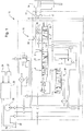
Fig. 1 , ableeding system 10 includes a hydraulicdirectional control valve 12 formed by selective control valve (SCV) which has amain spool 18 which controls the flow of pressurized hydraulic fluid to a hydraulic function, such as ahydraulic cylinder 14 which is connected to theselective control valve 12 byhydraulic connectors check valves Main spool 18 is moved by hydraulic pressure controlled by solenoid operatedpilot valve 20.Selective control valve 12 is connected to a hydraulic (clean oil)reservoir 28 and to apump 32.Selective control valve 12 is controlled by avalve control unit 22 formed by an electronic control unit (ECU) which supplies signals to the solenoids of thepilot valve 20. ECU 22 responds to the operation of a conventionalcontrol valve lever 24, and receives a temperature signal fromtemperature sensor 26 and a vehicle speed signal from avehicle speed sensor 27.Main spool 18 is movable from a neutral or closed position C, to a retract position R, an extend position E and to a float position F. - As best seen in
Fig. 2 ,selective control valve 12 is of conventional type and includes ahousing 40 with amain valve bore 42.Main spool 18 is shown in the neutral position and is controlled bypilot valve 20.Main valve bore 42 is communicated with a sump or tank passage 44, a pair ofpump passages 46, and a pair ofwork ports 48 and 50.Pump passages 46 are communicated to a pump port 51.Work ports 48 and 50 are connected to thehydraulic cylinder 14 viacheck valves hydraulic connectors Main spool 18 includeslands 52, 54 and 56. Thelands 52, 54 and 56 as well as thepassages 44 and 46 are dimensioned so that whenmain spool 18 is moved a small distance to the right, such as a few millimeters for example,land 56 communicates tank passage 44 to work port 48 before land 52 communicatespump passage 46 to workport 50. This bleeds and releases trapped pressurized hydraulic fluid from work port 48. Similarly, whenspool 18 is moved a small distance to the left, such as a few millimeters for example, land 54 communicates tank passage 44 to workport 50 beforeland 56 communicatespump passage 46 to work port 48. This bleeds and releases trapped pressurized hydraulic fluid fromwork port 50. - The
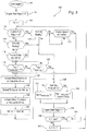
ECU 22 repeatedly executes analgorithm 100 represented byFig. 3 . The conversion of the above flow chart into a standard language for implementing the algorithm described by the flow chart in a digital computer or microprocessor, will be evident to one with ordinary skill in the art. - The algorithm starts at
step 102 upon start-up of the vehicle engine (not shown). - Step 104 sets an Engine Start Flag x = 0.
-
Step 106 sets an SCV index number N = 1. - If the Engine Start Flag is x = 0, then step 108 directs control to
step 110, else tostep 114. - If the Nth SCV is flowing,
step 110 directs control tostep 130, else tostep 112. - If vehicle speed is greater than or equal to a threshold speed, such as 0.5 KPH, then step 112 directs control to
step 122, else back tostep 112. - If the Nth SCV is flowing, step 114 directs control to
step 130, else tostep 116. - If vehicle speed is greater than or equal to a threshold speed, such as 0.5 KPH, then
step 116 directs control tostep 118, else back tostep 116. - If the hydraulic reservoir temperature TRes, is greater than or equal to a reference temperature TRefSCV(N) associated with the Nth SCV plus 10 °C, then step 118 directs control to
step 122, else tostep 120. - If the hydraulic reservoir temperature TRes, is less than reference temperature TRefSCV(N), then step 120 directs control to
step 130, else back tostep 118. -
Step 122 generates an extend bleed command for 40 milliseconds. This causes themain spool 18 to move to the left, viewingFig. 2 , to an extend bleed position wherein work port 48 is connected to sump passage 44 whilework port 50 remains blocked with respect to bothpump passage 46 and sump passage 44. -
Step 124 then generates a neutral command which movesmain spool 18 to its neutral position for 100 milliseconds. - Next,
step 126 generates a retract bleed command for 40 milliseconds. This causes themain spool 18 to move to the right, viewingFig. 2 , to a retract bleed position whereinwork port 50 is connected to sump passage 44 while work port 48 remains blocked with respect to bothpump passage 46 and sump passage 44. -
Step 128 generates a command to move themain spool 18 back to neutral, then directs control tostep 130. - If the hydraulic reservoir temperature TRes is greater than or equal to 0 °C, then step 130 directs control to
step 134, else tostep 132. -
Step 132 sets the reference temperature TRefSCV(N) for the Nth SCV equal to 0 °C, then directs control tostep 136. -
Step 134 sets the reference temperature TRefSCV(N) equal to the current hydraulic reservoir temperature TRes, then directs control tostep 136. -
Step 136 sets the Engine Start Flag x = 1, then directs control tostep 138. - If N is equal to its maximum value, indicating that this process has been performed for all SCVs, then
step 138 directs control tostep 140, else tostep 142. -
Step 140 sets the SCV index N = 1, and directs control tostep 108. - Step 142 increases the SCV index value N by 1, and directs control to step 108.
- The resulting system automatically commands the
main spool 18 to move to a position where one of thework ports 48, 50 is allowed to drain without opening the pressure port, so that trapped pressure in the system is bled. This command can be issued at several points in the operation of the vehicle, such as startup, engine running and engine shutdown. This prevents the pressure from building up to a point where a physical thermal relief valve would be necessary. - The system of this invention generates a first bleed command to hold the
main spool 18 in the first bleed position for a first time period, after which theECU 22 generates a neutral command to hold themain spool 18 in its neutral position for a second time period, and after which theECU 22 generates the second bleed command to hold themain spool 18 in the second bleed position for a third time period. Preferably, the first time period is shorter (approx. 40 milliseconds) than the second time period (approx. 100 milliseconds). Preferably, the first time period is equal to the third time period. - Preferably, the
ECU 22 prevents generation of a bleed command if theselective control valve 12 is in its extend or retract position, prevents generation of a bleed command if a temperature of hydraulic fluid in thehydraulic reservoir 28 is not less than a reference temperature, and prevents generation of a bleed command if a speed of the vehicle is less than a reference speed. - Preferably, the
ECU 22 automatically returns themain spool 18 to its neutral position after the first and second bleed commands have been generated. - This system can be used to limit pressure buildup in an uncoupled SCV to a pressure such as 350 bar by allowing a retract or extend command to bleed off the pressure between the
check valves hydraulic connectors - The length of time to issue the bleed command to both the extend and retract position should be minimized to assure the decay of 350 bar of pressure to less than 25 bar for an uncoupled SCV, but limit the amount of oil bleed from the work port. This time can be determined experimentally based on lab tests and simulations. The expected time is preferably less than 40 milliseconds and preferably between 10 to 20 milliseconds.
- Preferably, a bleed event is prevented if hydraulic reservoir temperature is less than 0 °C.
- Preferably, as a special case, after vehicle start, a bleed event is performed only if the vehicle speed is not less than 0.5 KPH. Then, after vehicle motion has begun, subsequent bleed events require both a hydraulic reservoir temperature change of 10 °C and a vehicle speed not less than 0.5 KPH.
- Preferably, a bleed event may be commanded to occur on all SCVs for both retract and extend, unless a SCV is currently commanded by the operator to be flowing oil, in which case the bleed event can be skipped.
- The reference temperature from which the 10 °C increase is measured and set at the following conditions: 1) when the vehicle is initially started, 2) when a bleed event is commanded, and 3) while the vehicle is running for every 1 °C decrease in hydraulic reservoir temperature from the last set point.
- This feature can be added at a low product cost in software with a high reliability. The pressure relief can be programmed to only occur when the potential for pressure increases due to thermal expansion are present. There is no hysteresis like physical relief valves as the main spool is commanded to a specific position. In a hydraulic system having multiple SCVs, the system operates to automatically and sequentially bleed the valves.
Claims (12)
- A vehicle hydraulic system including
a valve control unit (22) and
a hydraulic directional control valve (12) having
first and second work ports (48, 50), a first and a second pilot operated check valve (34, 36), wherein the first and second work ports (48, 50) are connected to the respective first and second pilot operated check valve (34, 36), and a main spool (18) for controlling communication between a pump (32), a hydraulic reservoir (28) and the first and the second work ports (48, 50),
the main spool (18) being movable from a neutral position to an extend position and to a retract position and to respective first and second bleed positions wherein the respective work port (48, 50) is communicated with the hydraulic reservoir (28), wherein
the valve control unit (22) automatically generates first and second bleed commands, the main spool (18) being movable, in response to the first bleed command, to the first bleed position wherein a first one of the work ports (48, 50) is communicated with the hydraulic reservoir (28) and a second one of the work ports (50, 48) is not communicated with the pump (32), and, in response to the second bleed command, to the second bleed position wherein the second work port (50, 48) is communicated with the hydraulic reservoir (28) and the first work port (48, 50) is not communicated with the pump (32); and the valve control unit (22) generating the first bleed command to hold the main spool (18) in the first bleed position for a first time period, after which the valve control unit (22) generates a neutral command to hold the main spool (18) in its neutral position for a second time period, and after which the valve control unit (22) generates the second bleed command to hold the main spool (18) in the second bleed position for a third time period. - The system according to claim 1, characterized in that the first time period is shorter than the second time period.
- The system according to claim 1 or 2, characterized in that the first time period is equal to the third time period.
- The system according to one of claims 1 to 3. characterized in that the valve control unit (22) prevents generation of a bleed command if the directional control valve (12) is being commanded to flow oil.
- The system according to one of claims 1 to 4, characterized in that the valve control unit (22) prevents generation of a bleed command if the directional control valve (12) is in its extend position.
- The system according to one of claims 1 to 5, characterized in that the valve control unit (22) prevents generation of a bleed command if the directional control valve (12) is in its retract position.
- The system according to one of claims 1 to 6, characterized in that the valve control unit (22) prevents generation of a bleed command if a hydraulic reservoir temperature is not less than a reference temperature.
- The system according to one of claim 7, characterized in that the valve control unit (22) modifies the reference temperature if the directional control valve (12) is commanded to flow hydraulic fluid by an operator.
- The system according to one of claims 1 to 8, characterized in that the valve control unit (22) prevents generation of a bleed command if a speed of the vehicle is less than a reference speed.
- The system according to one of claims 1 to 9, characterized in that the valve control unit (22) automatically returns the main spool (18) to its neutral position after the first and second bleed commands have been generated.
- The system according to claim 1, characterized by further including a temperature sensor (26) for sensing a temperature of hydraulic fluid in the hydraulic reservoir (28) and generating a temperature signal which is communicated to the valve control unit (22), the valve control unit (22) automatically generating a bleed command when the sensed hydraulic reservoir temperature is at least a reference temperature, the main spool (18) being movable, in response to the bleed command, to the bleed position.
- The system according to claim 11, characterized by further including a vehicle speed sensor (27) for sensing a speed of the vehicle and generating a vehicle speed signal which is communicated to the valve control unit (22), the valve control unit (22) automatically generating a bleed command when the vehicle speed is at least a threshold speed and the sensed hydraulic reservoir temperature is at least the reference temperature, the main spool (18) being movable, in response to the bleed command, to the bleed position.
Applications Claiming Priority (1)
| Application Number | Priority Date | Filing Date | Title |
|---|---|---|---|
| US12/256,190 US20100096576A1 (en) | 2008-10-22 | 2008-10-22 | Valve bleed system |
Publications (3)
| Publication Number | Publication Date |
|---|---|
| EP2179902A2 EP2179902A2 (en) | 2010-04-28 |
| EP2179902A3 EP2179902A3 (en) | 2013-01-30 |
| EP2179902B1 true EP2179902B1 (en) | 2017-07-05 |
Family
ID=41395928
Family Applications (1)
| Application Number | Title | Priority Date | Filing Date |
|---|---|---|---|
| EP09172451.8A Active EP2179902B1 (en) | 2008-10-22 | 2009-10-07 | System for bleeding a valve in a vehicle hydraulic system |
Country Status (3)
| Country | Link |
|---|---|
| US (2) | US20100096576A1 (en) |
| EP (1) | EP2179902B1 (en) |
| BR (1) | BRPI0904205A2 (en) |
Families Citing this family (6)
| Publication number | Priority date | Publication date | Assignee | Title |
|---|---|---|---|---|
| US9476432B2 (en) * | 2013-10-04 | 2016-10-25 | Husco International, Inc. | Hydraulic valve assembly with tank return flow compensation |
| US9459630B2 (en) * | 2013-10-22 | 2016-10-04 | Fisher Controls International Llc | System and method for controlling a remote valve |
| US9403434B2 (en) * | 2014-01-20 | 2016-08-02 | Posi-Plus Technologies Inc. | Hydraulic system for extreme climates |
| US10160433B2 (en) * | 2016-09-21 | 2018-12-25 | Ford Global Technologies, Llc | Hydraulic brake apparatus and related methods |
| US10457265B2 (en) * | 2017-03-09 | 2019-10-29 | Ford Global Technologies, Llc | Methods and apparatus to facilitate brake bleeding |
| CN108909697B (en) * | 2018-07-27 | 2020-08-18 | 中国煤炭科工集团太原研究院有限公司 | Mining explosion-proof type electro-hydraulic brake valve |
Family Cites Families (12)
| Publication number | Priority date | Publication date | Assignee | Title |
|---|---|---|---|---|
| US4718329A (en) * | 1985-02-04 | 1988-01-12 | Hitachi Construction Machinery Co., Ltd. | Control system for hydraulic circuit |
| WO1998026132A1 (en) * | 1996-12-12 | 1998-06-18 | Shin Caterpillar Mitsubishi Ltd. | Control device of construction machine |
| GB0111918D0 (en) * | 2001-05-16 | 2001-07-04 | Ford New Holland Nv | Control arrangement and method for a hydraulic system |
| US6907901B2 (en) * | 2002-06-03 | 2005-06-21 | Borgwarner Inc. | Solenoid control valve |
| US6866063B2 (en) * | 2002-09-06 | 2005-03-15 | Delphi Technologies, Inc. | Low leak pressure control actuator |
| JP2005054970A (en) * | 2003-08-07 | 2005-03-03 | Jatco Ltd | Linear solenoid valve control device |
| US7126464B2 (en) * | 2003-11-19 | 2006-10-24 | Qualcomm Incorporated | Method and apparatus for controlling a valve during a hazard event |
| FR2864178B1 (en) * | 2003-12-23 | 2006-02-17 | Giat Ind Sa | CONTROL DEVICE IN POSITION OF A HYDRAULIC ACTUATOR AND SERVOVALVE INTERFACE PLATE USING SUCH A DEVICE |
| US7475895B2 (en) * | 2004-06-15 | 2009-01-13 | Delphi Technologies, Inc. | Hydraulic circuit for a stabilizer bar |
| US7441546B2 (en) * | 2005-07-28 | 2008-10-28 | Denso Corporation | Valve apparatus |
| JP2007146945A (en) * | 2005-11-25 | 2007-06-14 | Kubota Corp | Valve |
| US20070246111A1 (en) * | 2006-04-19 | 2007-10-25 | Santos Burrola | Actuating valve with control port vent to ameliorate supply pressure fluctuation |
-
2008
- 2008-10-22 US US12/256,190 patent/US20100096576A1/en not_active Abandoned
-
2009
- 2009-10-07 EP EP09172451.8A patent/EP2179902B1/en active Active
- 2009-10-20 BR BRPI0904205-9A patent/BRPI0904205A2/en not_active IP Right Cessation
-
2014
- 2014-07-08 US US14/325,945 patent/US20140318652A1/en not_active Abandoned
Also Published As
| Publication number | Publication date |
|---|---|
| US20140318652A1 (en) | 2014-10-30 |
| EP2179902A2 (en) | 2010-04-28 |
| EP2179902A3 (en) | 2013-01-30 |
| BRPI0904205A2 (en) | 2010-09-14 |
| US20100096576A1 (en) | 2010-04-22 |
Similar Documents
| Publication | Publication Date | Title |
|---|---|---|
| US20140318652A1 (en) | Valve bleed system | |
| EP2071195B1 (en) | Hydraulic circuit with load holding valves operated by external pilot pressure | |
| EP2904365B1 (en) | Automatic oil spill detection system | |
| EP2507519B1 (en) | Out-of-range sensor recalibration | |
| KR101832508B1 (en) | Method of operating a control valve assembly for a hydraulic system | |
| JP4909164B2 (en) | Construction equipment warm-up equipment | |
| EP3255284B1 (en) | Flow control valve for construction machine | |
| KR102389687B1 (en) | Control system for construction machinery | |
| US7213502B2 (en) | Robustly stable servo-controlled metering poppet valve | |
| US20150101676A1 (en) | Valve Block having a Valve Assembly | |
| JP2012030741A (en) | Aircraft actuator control device | |
| US9903396B2 (en) | Valve assembly | |
| KR101832507B1 (en) | Method for operating a hydraulic actuation power system experiencing pressure sensor faults | |
| CN107917114B (en) | Method for detecting non-commanded spool positioning and preventing fluid flow to a hydraulic actuator | |
| EP2093431B1 (en) | Hydraulic circuit of construction machine | |
| JP2004225867A (en) | Hydraulic control device for work machine | |
| JP2007046712A (en) | Hydraulic driving device | |
| KR102167422B1 (en) | Pressure limited flow priority boost | |
| US10443758B2 (en) | Systems and methods for electrohydraulic valve calibration | |
| US20120205563A1 (en) | Valve arrangement for actuating a load | |
| CN110382786B (en) | Control system for construction machine and control method for construction machine | |
| GB1563937A (en) | Demand compensated hydraulic system | |
| CN111791949A (en) | Hydraulic steering arrangement | |
| JP2008089030A (en) | Hydraulic control device | |
| US20210207622A1 (en) | Flow control valve and hydraulic machine including the same |
Legal Events
| Date | Code | Title | Description |
|---|---|---|---|
| PUAI | Public reference made under article 153(3) epc to a published international application that has entered the european phase |
Free format text: ORIGINAL CODE: 0009012 |
|
| AK | Designated contracting states |
Kind code of ref document: A2 Designated state(s): AT BE BG CH CY CZ DE DK EE ES FI FR GB GR HR HU IE IS IT LI LT LU LV MC MK MT NL NO PL PT RO SE SI SK SM TR |
|
| AX | Request for extension of the european patent |
Extension state: AL BA RS |
|
| PUAL | Search report despatched |
Free format text: ORIGINAL CODE: 0009013 |
|
| AK | Designated contracting states |
Kind code of ref document: A3 Designated state(s): AT BE BG CH CY CZ DE DK EE ES FI FR GB GR HR HU IE IS IT LI LT LU LV MC MK MT NL NO PL PT RO SE SI SK SM TR |
|
| AX | Request for extension of the european patent |
Extension state: AL BA RS |
|
| RIC1 | Information provided on ipc code assigned before grant |
Ipc: B60T 11/30 20060101AFI20121221BHEP Ipc: F15B 11/00 20060101ALI20121221BHEP Ipc: B60T 17/22 20060101ALI20121221BHEP Ipc: B60T 13/68 20060101ALI20121221BHEP |
|
| 17P | Request for examination filed |
Effective date: 20130730 |
|
| RBV | Designated contracting states (corrected) |
Designated state(s): AT BE BG CH CY CZ DE DK EE ES FI FR GB GR HR HU IE IS IT LI LT LU LV MC MK MT NL NO PL PT RO SE SI SK SM TR |
|
| GRAP | Despatch of communication of intention to grant a patent |
Free format text: ORIGINAL CODE: EPIDOSNIGR1 |
|
| INTG | Intention to grant announced |
Effective date: 20170125 |
|
| GRAS | Grant fee paid |
Free format text: ORIGINAL CODE: EPIDOSNIGR3 |
|
| GRAA | (expected) grant |
Free format text: ORIGINAL CODE: 0009210 |
|
| AK | Designated contracting states |
Kind code of ref document: B1 Designated state(s): AT BE BG CH CY CZ DE DK EE ES FI FR GB GR HR HU IE IS IT LI LT LU LV MC MK MT NL NO PL PT RO SE SI SK SM TR |
|
| REG | Reference to a national code |
Ref country code: GB Ref legal event code: FG4D |
|
| REG | Reference to a national code |
Ref country code: CH Ref legal event code: EP |
|
| REG | Reference to a national code |
Ref country code: AT Ref legal event code: REF Ref document number: 906367 Country of ref document: AT Kind code of ref document: T Effective date: 20170715 |
|
| REG | Reference to a national code |
Ref country code: IE Ref legal event code: FG4D |
|
| REG | Reference to a national code |
Ref country code: DE Ref legal event code: R096 Ref document number: 602009046942 Country of ref document: DE |
|
| REG | Reference to a national code |
Ref country code: NL Ref legal event code: MP Effective date: 20170705 |
|
| REG | Reference to a national code |
Ref country code: AT Ref legal event code: MK05 Ref document number: 906367 Country of ref document: AT Kind code of ref document: T Effective date: 20170705 |
|
| REG | Reference to a national code |
Ref country code: LT Ref legal event code: MG4D |
|
| PG25 | Lapsed in a contracting state [announced via postgrant information from national office to epo] |
Ref country code: AT Free format text: LAPSE BECAUSE OF FAILURE TO SUBMIT A TRANSLATION OF THE DESCRIPTION OR TO PAY THE FEE WITHIN THE PRESCRIBED TIME-LIMIT Effective date: 20170705 Ref country code: SE Free format text: LAPSE BECAUSE OF FAILURE TO SUBMIT A TRANSLATION OF THE DESCRIPTION OR TO PAY THE FEE WITHIN THE PRESCRIBED TIME-LIMIT Effective date: 20170705 Ref country code: NL Free format text: LAPSE BECAUSE OF FAILURE TO SUBMIT A TRANSLATION OF THE DESCRIPTION OR TO PAY THE FEE WITHIN THE PRESCRIBED TIME-LIMIT Effective date: 20170705 Ref country code: HR Free format text: LAPSE BECAUSE OF FAILURE TO SUBMIT A TRANSLATION OF THE DESCRIPTION OR TO PAY THE FEE WITHIN THE PRESCRIBED TIME-LIMIT Effective date: 20170705 Ref country code: NO Free format text: LAPSE BECAUSE OF FAILURE TO SUBMIT A TRANSLATION OF THE DESCRIPTION OR TO PAY THE FEE WITHIN THE PRESCRIBED TIME-LIMIT Effective date: 20171005 Ref country code: FI Free format text: LAPSE BECAUSE OF FAILURE TO SUBMIT A TRANSLATION OF THE DESCRIPTION OR TO PAY THE FEE WITHIN THE PRESCRIBED TIME-LIMIT Effective date: 20170705 Ref country code: LT Free format text: LAPSE BECAUSE OF FAILURE TO SUBMIT A TRANSLATION OF THE DESCRIPTION OR TO PAY THE FEE WITHIN THE PRESCRIBED TIME-LIMIT Effective date: 20170705 |
|
| PG25 | Lapsed in a contracting state [announced via postgrant information from national office to epo] |
Ref country code: BG Free format text: LAPSE BECAUSE OF FAILURE TO SUBMIT A TRANSLATION OF THE DESCRIPTION OR TO PAY THE FEE WITHIN THE PRESCRIBED TIME-LIMIT Effective date: 20171005 Ref country code: ES Free format text: LAPSE BECAUSE OF FAILURE TO SUBMIT A TRANSLATION OF THE DESCRIPTION OR TO PAY THE FEE WITHIN THE PRESCRIBED TIME-LIMIT Effective date: 20170705 Ref country code: LV Free format text: LAPSE BECAUSE OF FAILURE TO SUBMIT A TRANSLATION OF THE DESCRIPTION OR TO PAY THE FEE WITHIN THE PRESCRIBED TIME-LIMIT Effective date: 20170705 Ref country code: IS Free format text: LAPSE BECAUSE OF FAILURE TO SUBMIT A TRANSLATION OF THE DESCRIPTION OR TO PAY THE FEE WITHIN THE PRESCRIBED TIME-LIMIT Effective date: 20171105 Ref country code: GR Free format text: LAPSE BECAUSE OF FAILURE TO SUBMIT A TRANSLATION OF THE DESCRIPTION OR TO PAY THE FEE WITHIN THE PRESCRIBED TIME-LIMIT Effective date: 20171006 Ref country code: PL Free format text: LAPSE BECAUSE OF FAILURE TO SUBMIT A TRANSLATION OF THE DESCRIPTION OR TO PAY THE FEE WITHIN THE PRESCRIBED TIME-LIMIT Effective date: 20170705 |
|
| REG | Reference to a national code |
Ref country code: DE Ref legal event code: R097 Ref document number: 602009046942 Country of ref document: DE |
|
| PG25 | Lapsed in a contracting state [announced via postgrant information from national office to epo] |
Ref country code: RO Free format text: LAPSE BECAUSE OF FAILURE TO SUBMIT A TRANSLATION OF THE DESCRIPTION OR TO PAY THE FEE WITHIN THE PRESCRIBED TIME-LIMIT Effective date: 20170705 Ref country code: CZ Free format text: LAPSE BECAUSE OF FAILURE TO SUBMIT A TRANSLATION OF THE DESCRIPTION OR TO PAY THE FEE WITHIN THE PRESCRIBED TIME-LIMIT Effective date: 20170705 Ref country code: DK Free format text: LAPSE BECAUSE OF FAILURE TO SUBMIT A TRANSLATION OF THE DESCRIPTION OR TO PAY THE FEE WITHIN THE PRESCRIBED TIME-LIMIT Effective date: 20170705 |
|
| PLBE | No opposition filed within time limit |
Free format text: ORIGINAL CODE: 0009261 |
|
| STAA | Information on the status of an ep patent application or granted ep patent |
Free format text: STATUS: NO OPPOSITION FILED WITHIN TIME LIMIT |
|
| PG25 | Lapsed in a contracting state [announced via postgrant information from national office to epo] |
Ref country code: SK Free format text: LAPSE BECAUSE OF FAILURE TO SUBMIT A TRANSLATION OF THE DESCRIPTION OR TO PAY THE FEE WITHIN THE PRESCRIBED TIME-LIMIT Effective date: 20170705 Ref country code: SM Free format text: LAPSE BECAUSE OF FAILURE TO SUBMIT A TRANSLATION OF THE DESCRIPTION OR TO PAY THE FEE WITHIN THE PRESCRIBED TIME-LIMIT Effective date: 20170705 Ref country code: EE Free format text: LAPSE BECAUSE OF FAILURE TO SUBMIT A TRANSLATION OF THE DESCRIPTION OR TO PAY THE FEE WITHIN THE PRESCRIBED TIME-LIMIT Effective date: 20170705 Ref country code: IT Free format text: LAPSE BECAUSE OF FAILURE TO SUBMIT A TRANSLATION OF THE DESCRIPTION OR TO PAY THE FEE WITHIN THE PRESCRIBED TIME-LIMIT Effective date: 20170705 Ref country code: MC Free format text: LAPSE BECAUSE OF FAILURE TO SUBMIT A TRANSLATION OF THE DESCRIPTION OR TO PAY THE FEE WITHIN THE PRESCRIBED TIME-LIMIT Effective date: 20170705 |
|
| REG | Reference to a national code |
Ref country code: CH Ref legal event code: PL |
|
| 26N | No opposition filed |
Effective date: 20180406 |
|
| GBPC | Gb: european patent ceased through non-payment of renewal fee |
Effective date: 20171007 |
|
| REG | Reference to a national code |
Ref country code: IE Ref legal event code: MM4A |
|
| REG | Reference to a national code |
Ref country code: FR Ref legal event code: ST Effective date: 20180629 |
|
| PG25 | Lapsed in a contracting state [announced via postgrant information from national office to epo] |
Ref country code: GB Free format text: LAPSE BECAUSE OF NON-PAYMENT OF DUE FEES Effective date: 20171007 Ref country code: LI Free format text: LAPSE BECAUSE OF NON-PAYMENT OF DUE FEES Effective date: 20171031 Ref country code: LU Free format text: LAPSE BECAUSE OF NON-PAYMENT OF DUE FEES Effective date: 20171007 Ref country code: CH Free format text: LAPSE BECAUSE OF NON-PAYMENT OF DUE FEES Effective date: 20171031 |
|
| REG | Reference to a national code |
Ref country code: BE Ref legal event code: MM Effective date: 20171031 |
|
| PG25 | Lapsed in a contracting state [announced via postgrant information from national office to epo] |
Ref country code: FR Free format text: LAPSE BECAUSE OF NON-PAYMENT OF DUE FEES Effective date: 20171031 Ref country code: SI Free format text: LAPSE BECAUSE OF FAILURE TO SUBMIT A TRANSLATION OF THE DESCRIPTION OR TO PAY THE FEE WITHIN THE PRESCRIBED TIME-LIMIT Effective date: 20170705 Ref country code: BE Free format text: LAPSE BECAUSE OF NON-PAYMENT OF DUE FEES Effective date: 20171031 |
|
| PG25 | Lapsed in a contracting state [announced via postgrant information from national office to epo] |
Ref country code: MT Free format text: LAPSE BECAUSE OF NON-PAYMENT OF DUE FEES Effective date: 20171007 |
|
| PG25 | Lapsed in a contracting state [announced via postgrant information from national office to epo] |
Ref country code: IE Free format text: LAPSE BECAUSE OF NON-PAYMENT OF DUE FEES Effective date: 20171007 |
|
| PG25 | Lapsed in a contracting state [announced via postgrant information from national office to epo] |
Ref country code: HU Free format text: LAPSE BECAUSE OF FAILURE TO SUBMIT A TRANSLATION OF THE DESCRIPTION OR TO PAY THE FEE WITHIN THE PRESCRIBED TIME-LIMIT; INVALID AB INITIO Effective date: 20091007 |
|
| PG25 | Lapsed in a contracting state [announced via postgrant information from national office to epo] |
Ref country code: CY Free format text: LAPSE BECAUSE OF NON-PAYMENT OF DUE FEES Effective date: 20170705 |
|
| PG25 | Lapsed in a contracting state [announced via postgrant information from national office to epo] |
Ref country code: MK Free format text: LAPSE BECAUSE OF FAILURE TO SUBMIT A TRANSLATION OF THE DESCRIPTION OR TO PAY THE FEE WITHIN THE PRESCRIBED TIME-LIMIT Effective date: 20170705 |
|
| PG25 | Lapsed in a contracting state [announced via postgrant information from national office to epo] |
Ref country code: TR Free format text: LAPSE BECAUSE OF FAILURE TO SUBMIT A TRANSLATION OF THE DESCRIPTION OR TO PAY THE FEE WITHIN THE PRESCRIBED TIME-LIMIT Effective date: 20170705 |
|
| PG25 | Lapsed in a contracting state [announced via postgrant information from national office to epo] |
Ref country code: PT Free format text: LAPSE BECAUSE OF FAILURE TO SUBMIT A TRANSLATION OF THE DESCRIPTION OR TO PAY THE FEE WITHIN THE PRESCRIBED TIME-LIMIT Effective date: 20170705 |
|
| PGFP | Annual fee paid to national office [announced via postgrant information from national office to epo] |
Ref country code: DE Payment date: 20230920 Year of fee payment: 15 |