EP2179836A1 - Plastic skin and method for its production - Google Patents
Plastic skin and method for its production Download PDFInfo
- Publication number
- EP2179836A1 EP2179836A1 EP08075849A EP08075849A EP2179836A1 EP 2179836 A1 EP2179836 A1 EP 2179836A1 EP 08075849 A EP08075849 A EP 08075849A EP 08075849 A EP08075849 A EP 08075849A EP 2179836 A1 EP2179836 A1 EP 2179836A1
- Authority
- EP
- European Patent Office
- Prior art keywords
- insert
- film
- mold
- molded skin
- skin
- Prior art date
- Legal status (The legal status is an assumption and is not a legal conclusion. Google has not performed a legal analysis and makes no representation as to the accuracy of the status listed.)
- Granted
Links
- 238000000034 method Methods 0.000 title claims abstract description 32
- 239000004033 plastic Substances 0.000 title claims abstract description 6
- 229920003023 plastic Polymers 0.000 title claims abstract description 6
- 238000004519 manufacturing process Methods 0.000 title claims description 7
- 229920002397 thermoplastic olefin Polymers 0.000 claims abstract description 8
- 239000002184 metal Substances 0.000 claims abstract description 4
- 239000002023 wood Substances 0.000 claims abstract description 4
- 239000000463 material Substances 0.000 claims description 7
- 239000011888 foil Substances 0.000 claims description 5
- 230000001070 adhesive effect Effects 0.000 claims description 3
- 239000000853 adhesive Substances 0.000 claims description 2
- 239000010410 layer Substances 0.000 description 12
- 238000011161 development Methods 0.000 description 6
- 230000018109 developmental process Effects 0.000 description 6
- 238000007666 vacuum forming Methods 0.000 description 4
- 230000001419 dependent effect Effects 0.000 description 2
- 230000002349 favourable effect Effects 0.000 description 2
- 238000010438 heat treatment Methods 0.000 description 2
- 238000003475 lamination Methods 0.000 description 2
- 238000000465 moulding Methods 0.000 description 2
- 239000002985 plastic film Substances 0.000 description 2
- 229920006255 plastic film Polymers 0.000 description 2
- 239000002356 single layer Substances 0.000 description 2
- 238000006243 chemical reaction Methods 0.000 description 1
- 230000006835 compression Effects 0.000 description 1
- 238000007906 compression Methods 0.000 description 1
- 238000007796 conventional method Methods 0.000 description 1
- 238000001816 cooling Methods 0.000 description 1
- 238000006073 displacement reaction Methods 0.000 description 1
- 230000000694 effects Effects 0.000 description 1
- 238000004049 embossing Methods 0.000 description 1
- 238000005516 engineering process Methods 0.000 description 1
- 238000005187 foaming Methods 0.000 description 1
- 238000002347 injection Methods 0.000 description 1
- 239000007924 injection Substances 0.000 description 1
- 238000002360 preparation method Methods 0.000 description 1
- 238000004321 preservation Methods 0.000 description 1
- 238000003825 pressing Methods 0.000 description 1
- 230000000754 repressing effect Effects 0.000 description 1
- 238000007493 shaping process Methods 0.000 description 1
- 210000002023 somite Anatomy 0.000 description 1
Images

Classifications
-
- B—PERFORMING OPERATIONS; TRANSPORTING
- B29—WORKING OF PLASTICS; WORKING OF SUBSTANCES IN A PLASTIC STATE IN GENERAL
- B29C—SHAPING OR JOINING OF PLASTICS; SHAPING OF MATERIAL IN A PLASTIC STATE, NOT OTHERWISE PROVIDED FOR; AFTER-TREATMENT OF THE SHAPED PRODUCTS, e.g. REPAIRING
- B29C44/00—Shaping by internal pressure generated in the material, e.g. swelling or foaming ; Producing porous or cellular expanded plastics articles
- B29C44/02—Shaping by internal pressure generated in the material, e.g. swelling or foaming ; Producing porous or cellular expanded plastics articles for articles of definite length, i.e. discrete articles
- B29C44/12—Incorporating or moulding on preformed parts, e.g. inserts or reinforcements
- B29C44/14—Incorporating or moulding on preformed parts, e.g. inserts or reinforcements the preformed part being a lining
- B29C44/146—Shaping the lining before foaming
-
- B—PERFORMING OPERATIONS; TRANSPORTING
- B29—WORKING OF PLASTICS; WORKING OF SUBSTANCES IN A PLASTIC STATE IN GENERAL
- B29C—SHAPING OR JOINING OF PLASTICS; SHAPING OF MATERIAL IN A PLASTIC STATE, NOT OTHERWISE PROVIDED FOR; AFTER-TREATMENT OF THE SHAPED PRODUCTS, e.g. REPAIRING
- B29C45/00—Injection moulding, i.e. forcing the required volume of moulding material through a nozzle into a closed mould; Apparatus therefor
- B29C45/14—Injection moulding, i.e. forcing the required volume of moulding material through a nozzle into a closed mould; Apparatus therefor incorporating preformed parts or layers, e.g. injection moulding around inserts or for coating articles
- B29C45/1418—Injection moulding, i.e. forcing the required volume of moulding material through a nozzle into a closed mould; Apparatus therefor incorporating preformed parts or layers, e.g. injection moulding around inserts or for coating articles the inserts being deformed or preformed, e.g. by the injection pressure
-
- B—PERFORMING OPERATIONS; TRANSPORTING
- B29—WORKING OF PLASTICS; WORKING OF SUBSTANCES IN A PLASTIC STATE IN GENERAL
- B29C—SHAPING OR JOINING OF PLASTICS; SHAPING OF MATERIAL IN A PLASTIC STATE, NOT OTHERWISE PROVIDED FOR; AFTER-TREATMENT OF THE SHAPED PRODUCTS, e.g. REPAIRING
- B29C51/00—Shaping by thermoforming, i.e. shaping sheets or sheet like preforms after heating, e.g. shaping sheets in matched moulds or by deep-drawing; Apparatus therefor
- B29C51/04—Combined thermoforming and prestretching, e.g. biaxial stretching
-
- B—PERFORMING OPERATIONS; TRANSPORTING
- B29—WORKING OF PLASTICS; WORKING OF SUBSTANCES IN A PLASTIC STATE IN GENERAL
- B29C—SHAPING OR JOINING OF PLASTICS; SHAPING OF MATERIAL IN A PLASTIC STATE, NOT OTHERWISE PROVIDED FOR; AFTER-TREATMENT OF THE SHAPED PRODUCTS, e.g. REPAIRING
- B29C45/00—Injection moulding, i.e. forcing the required volume of moulding material through a nozzle into a closed mould; Apparatus therefor
- B29C45/14—Injection moulding, i.e. forcing the required volume of moulding material through a nozzle into a closed mould; Apparatus therefor incorporating preformed parts or layers, e.g. injection moulding around inserts or for coating articles
- B29C45/1418—Injection moulding, i.e. forcing the required volume of moulding material through a nozzle into a closed mould; Apparatus therefor incorporating preformed parts or layers, e.g. injection moulding around inserts or for coating articles the inserts being deformed or preformed, e.g. by the injection pressure
- B29C2045/14237—Injection moulding, i.e. forcing the required volume of moulding material through a nozzle into a closed mould; Apparatus therefor incorporating preformed parts or layers, e.g. injection moulding around inserts or for coating articles the inserts being deformed or preformed, e.g. by the injection pressure the inserts being deformed or preformed outside the mould or mould cavity
- B29C2045/14245—Injection moulding, i.e. forcing the required volume of moulding material through a nozzle into a closed mould; Apparatus therefor incorporating preformed parts or layers, e.g. injection moulding around inserts or for coating articles the inserts being deformed or preformed, e.g. by the injection pressure the inserts being deformed or preformed outside the mould or mould cavity using deforming or preforming means outside the mould cavity
-
- B—PERFORMING OPERATIONS; TRANSPORTING
- B29—WORKING OF PLASTICS; WORKING OF SUBSTANCES IN A PLASTIC STATE IN GENERAL
- B29C—SHAPING OR JOINING OF PLASTICS; SHAPING OF MATERIAL IN A PLASTIC STATE, NOT OTHERWISE PROVIDED FOR; AFTER-TREATMENT OF THE SHAPED PRODUCTS, e.g. REPAIRING
- B29C2791/00—Shaping characteristics in general
- B29C2791/001—Shaping in several steps
-
- B—PERFORMING OPERATIONS; TRANSPORTING
- B29—WORKING OF PLASTICS; WORKING OF SUBSTANCES IN A PLASTIC STATE IN GENERAL
- B29C—SHAPING OR JOINING OF PLASTICS; SHAPING OF MATERIAL IN A PLASTIC STATE, NOT OTHERWISE PROVIDED FOR; AFTER-TREATMENT OF THE SHAPED PRODUCTS, e.g. REPAIRING
- B29C45/00—Injection moulding, i.e. forcing the required volume of moulding material through a nozzle into a closed mould; Apparatus therefor
- B29C45/14—Injection moulding, i.e. forcing the required volume of moulding material through a nozzle into a closed mould; Apparatus therefor incorporating preformed parts or layers, e.g. injection moulding around inserts or for coating articles
- B29C45/1418—Injection moulding, i.e. forcing the required volume of moulding material through a nozzle into a closed mould; Apparatus therefor incorporating preformed parts or layers, e.g. injection moulding around inserts or for coating articles the inserts being deformed or preformed, e.g. by the injection pressure
- B29C45/14262—Clamping or tensioning means for the insert
-
- B—PERFORMING OPERATIONS; TRANSPORTING
- B29—WORKING OF PLASTICS; WORKING OF SUBSTANCES IN A PLASTIC STATE IN GENERAL
- B29C—SHAPING OR JOINING OF PLASTICS; SHAPING OF MATERIAL IN A PLASTIC STATE, NOT OTHERWISE PROVIDED FOR; AFTER-TREATMENT OF THE SHAPED PRODUCTS, e.g. REPAIRING
- B29C51/00—Shaping by thermoforming, i.e. shaping sheets or sheet like preforms after heating, e.g. shaping sheets in matched moulds or by deep-drawing; Apparatus therefor
- B29C51/08—Deep drawing or matched-mould forming, i.e. using mechanical means only
- B29C51/082—Deep drawing or matched-mould forming, i.e. using mechanical means only by shaping between complementary mould parts
-
- B—PERFORMING OPERATIONS; TRANSPORTING
- B29—WORKING OF PLASTICS; WORKING OF SUBSTANCES IN A PLASTIC STATE IN GENERAL
- B29C—SHAPING OR JOINING OF PLASTICS; SHAPING OF MATERIAL IN A PLASTIC STATE, NOT OTHERWISE PROVIDED FOR; AFTER-TREATMENT OF THE SHAPED PRODUCTS, e.g. REPAIRING
- B29C51/00—Shaping by thermoforming, i.e. shaping sheets or sheet like preforms after heating, e.g. shaping sheets in matched moulds or by deep-drawing; Apparatus therefor
- B29C51/10—Forming by pressure difference, e.g. vacuum
-
- B—PERFORMING OPERATIONS; TRANSPORTING
- B29—WORKING OF PLASTICS; WORKING OF SUBSTANCES IN A PLASTIC STATE IN GENERAL
- B29C—SHAPING OR JOINING OF PLASTICS; SHAPING OF MATERIAL IN A PLASTIC STATE, NOT OTHERWISE PROVIDED FOR; AFTER-TREATMENT OF THE SHAPED PRODUCTS, e.g. REPAIRING
- B29C51/00—Shaping by thermoforming, i.e. shaping sheets or sheet like preforms after heating, e.g. shaping sheets in matched moulds or by deep-drawing; Apparatus therefor
- B29C51/12—Shaping by thermoforming, i.e. shaping sheets or sheet like preforms after heating, e.g. shaping sheets in matched moulds or by deep-drawing; Apparatus therefor of articles having inserts or reinforcements
-
- B—PERFORMING OPERATIONS; TRANSPORTING
- B29—WORKING OF PLASTICS; WORKING OF SUBSTANCES IN A PLASTIC STATE IN GENERAL
- B29K—INDEXING SCHEME ASSOCIATED WITH SUBCLASSES B29B, B29C OR B29D, RELATING TO MOULDING MATERIALS OR TO MATERIALS FOR MOULDS, REINFORCEMENTS, FILLERS OR PREFORMED PARTS, e.g. INSERTS
- B29K2105/00—Condition, form or state of moulded material or of the material to be shaped
- B29K2105/04—Condition, form or state of moulded material or of the material to be shaped cellular or porous
-
- B—PERFORMING OPERATIONS; TRANSPORTING
- B29—WORKING OF PLASTICS; WORKING OF SUBSTANCES IN A PLASTIC STATE IN GENERAL
- B29K—INDEXING SCHEME ASSOCIATED WITH SUBCLASSES B29B, B29C OR B29D, RELATING TO MOULDING MATERIALS OR TO MATERIALS FOR MOULDS, REINFORCEMENTS, FILLERS OR PREFORMED PARTS, e.g. INSERTS
- B29K2705/00—Use of metals, their alloys or their compounds, for preformed parts, e.g. for inserts
-
- B—PERFORMING OPERATIONS; TRANSPORTING
- B29—WORKING OF PLASTICS; WORKING OF SUBSTANCES IN A PLASTIC STATE IN GENERAL
- B29K—INDEXING SCHEME ASSOCIATED WITH SUBCLASSES B29B, B29C OR B29D, RELATING TO MOULDING MATERIALS OR TO MATERIALS FOR MOULDS, REINFORCEMENTS, FILLERS OR PREFORMED PARTS, e.g. INSERTS
- B29K2711/00—Use of natural products or their composites, not provided for in groups B29K2601/00 - B29K2709/00, for preformed parts, e.g. for inserts
- B29K2711/14—Wood, e.g. woodboard or fibreboard
-
- B—PERFORMING OPERATIONS; TRANSPORTING
- B29—WORKING OF PLASTICS; WORKING OF SUBSTANCES IN A PLASTIC STATE IN GENERAL
- B29L—INDEXING SCHEME ASSOCIATED WITH SUBCLASS B29C, RELATING TO PARTICULAR ARTICLES
- B29L2031/00—Other particular articles
- B29L2031/30—Vehicles, e.g. ships or aircraft, or body parts thereof
- B29L2031/3005—Body finishings
- B29L2031/3041—Trim panels
Definitions
- the present invention relates to a molded skin and a method for their preparation.
- the molded skin is particularly suitable for interior trim parts of motor vehicles.
- IMG in-mold graining
- the invention is therefore based on the object to provide a method for producing a molded skin or a molded skin, in which at low cost, an insert with a high-quality appearance can be fitted accurately in a molded skin.
- This object is achieved by a method for producing a molded skin according to claim 1 or by a molded skin according to claim 12.
- the method of the clamping frame against a positive mold for (pre-) deformation of the film ensures that a relatively uniform pre-stretching of the film takes place.
- the positive form forms an abutment for the depositor.
- the positive mold (which may also have, for example vacuum openings for attracting / positioning of the film) forms a mechanically strong abutment and is ensured by the predetermined shape that in the subsequent vacuum forming process in the negative mold no distortion or displacement of the insert due uneven strains occurs.
- the molded skin is completed.
- the preferably strongly heated film is converted accordingly or applied a desired surface structure.
- Thickness of the film achieved.
- the insert is adapted to be flush with the surface and essentially free of gaps in the rest of the mold skin, which greatly enhances the qualitative appearance of the molded skin.
- the molded skin according to the invention represents a three-dimensionally shaped film for covering an interior trim part for motor vehicles, wherein the insert is introduced in the manner described above on the side arranged to a motor vehicle interior.
- An advantageous development of the method consists in the fact that the molded skin is subsequently backfoamed, back-injected or embossed (or back-injection embossed) and / or provided with a carrier.
- a carrier for achieving a "soft-touch" effect or for lamination with the molded skin according to the invention.
- the positive mold touches a smaller surface area of the film than the negative mold.
- the positive form may have the same or a larger surface area of the film include as the negative mold. Normally, this surface area will be approximately the same in order to comprehensively achieve the above-described pre-deformation of the film by the positive mold.
- the positive form can also make up a significantly smaller percentage of the contacting surfaces.
- a small area of the positive mold (for example, between 1 and 5% contact surface with respect to the surface between negative mold and film) is possible in principle, if it is only about the stamping of the insert.
- a "compression ratio" is included, in which thus between positive mold and negative mold by pressing a conversion (additional) is achieved, larger overlaps and the abandonment of a residual gap between negative mold and positive mold in End state makes sense.
- a further advantageous embodiment provides that the stamping of the insert is carried out by a stamp which is introduced laterally into the tool containing the clamping frame. This makes it possible that a corresponding stamp is easy to retrofit to an existing mold. In molds that provide only a clamping frame and a negative mold, and the positive form can be brought laterally, especially if it should come into contact only with a very small surface area of the film to fulfill there the function of the plunger abutment.
- the film before contact with the positive mold has a temperature between 160 ° C and 250 ° C, preferably between 210 ° C and 220 ° C
- TPO thermoplastic olefin
- any other plastic films which are suitable for use in negative vacuum forming may also be used here.
- the choice of material at the depositor is relatively open, this can be made of plastic, metal, wood or similar materials. High temperature stability is advantageous for inserts.
- the insert is two-layered, wherein the top layer of the insert is removable from a rest insert before completing the molded skin or the interior trim part in order to achieve a circumferential and defined depression of the rest insert to the adjacent portion of the molded skin.
- the insert is not damaged by a certain surface structure of the negative vacuum molding tool.
- the depth offset between the insert and the section of the molded skin surrounding the insert should be between 1 and 10 mm, wherein the variations in the depth offset during one revolution of the visible edge contour of the insert are preferably less than 1 mm.
- the gap in the surface plane of the molded skin with respect to the insert should also be as small as possible, not exceeding 1 mm, preferably not more than 0.5 mm, particularly preferably 0.1 mm.
- a further advantageous development provides that the (residual) insert is set back from the surrounding molded skin and the radius of curvature of the edge of the molded skin around the insert is less than 3 mm, preferably less than 1 mm.
- Such small radii of curvature are easy to produce and yet to produce in the best quality, as by the removable top layer of the insert a corresponding specification of the edge structure by the upper layer edge contour of the insert is possible and thus (without high tooling costs) the edge structure of the skin around the rest of deposit around any is adjustable. It is also important here that by referencing the top layer to the rest of the deposits, the tolerances are significantly cheaper than in a specification of the edge structure of the molded skin by the negative mold, in which the spatial Relationship with the depositor would be tolerated.
- a further advantageous embodiment provides that the insert is designed as a placeholder, which is replaced before completion of the molded skin by a final deposit, which remains in the molded skin.
- the insert is designed as a placeholder, which is replaced before completion of the molded skin by a final deposit, which remains in the molded skin.
- the positive mold may additionally be provided with vacuum openings not shown here for sucking and fixing the film 3.
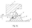
- the positive mold 5 After heating the film 3 and retracting the plate-shaped heater 9 in the in Fig. 1a Position shown moves the positive mold 5 against the film, so that in Fig. 1b shown picture results.
- the film 3 In this position, the film 3 is pre-formed, the film substantially takes on the shape of the positive mold 5, this is substantially corresponding to the shape of the female mold 7.
- the positive mold 5 stops and it is a two-layer insert 6 by means of a punch 8 pressed on the film 3.
- the insert consists of a top layer 6a and a rest insert 6b, wherein the in Fig. 1b shown underside of the rest insert is provided with a heat-activated adhesive, which has adhesive properties from about 40 ° C.
- the insert 6 consists of the existing plastic upper layer 6a and a wooden piece 6b.
- the punch 8 is eg by means of a pivoting mechanism (see pivoting direction about the vertical axis in Fig. 1b ) is pivoted between the positive mold 5 and the female mold 7, so that the stamp above the intended positioning of the insert 6 on the film 3 can be applied.
- the stamping takes place via a lifting movement, as in Fig. 1b shown on the left indicated by double arrow. Alternatively, an upward movement of the positive mold 5 can take place.
- the contact surface of the positive mold 5 with the film 3 is the same size as the contact surface of the negative mold 7 with the film 3.
- the insert can also be selected in one piece or it can also, an insert as a "placeholder" are inserted, which is replaced before completion of the molded skin by a final deposit that remains in the form of skin.
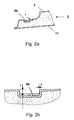
- the insert 6 or rest insert 6b is of high quality fitted into the rest of the molded skin. It is advantageous that the gap s (see Fig. 2b ) is as small as possible, in this case less than 0.1 mm. Even with a small residual gap, however, this is not very disturbing, as in Fig. 2b the rest insert 6b is set back relative to the surrounding skin by the depth offset t, this depth offset is in the present case 5 mm. The variations in the depth offset are presently less than 1 mm.
- the radius of curvature r (see Fig. 2a ) is also adjustable as desired, in this case it is less than 3 mm.
- the curvature can be predetermined here by a corresponding shaping of the upper layer 6a of the insert 6, here a corresponding edge contour can be provided on the side of the upper layer 6a facing the negative mold 7, with which virtually any edge geometries of the molded skin can be produced.
Abstract
Description
Die vorliegende Erfindung betrifft eine Formhaut sowie ein Verfahren zu deren Herstellung. Die Formhaut ist insbesondere für Innenverkleidungsteile von Kraftfahrzeugen geeignet.The present invention relates to a molded skin and a method for their preparation. The molded skin is particularly suitable for interior trim parts of motor vehicles.
Es ist bekannt, erwärmte Kunststofffolien mittels Unterdruck in eine Negativform zu ziehen, damit die Folie die Form bzw. auch die Oberflächenprägung der Negativform annimmt. Ein solches Verfahren ist als "In-Mold-Graining" (IMG) bekannt.It is known to draw heated plastic films by means of negative pressure in a negative mold, so that the film assumes the shape or the surface embossing of the negative mold. Such a method is known as in-mold graining (IMG).
Nachfolgend ist eine Hinterschäumung der Formhaut möglich bzw. eine Kaschierung auf einem Träger, um so ein fertiges Innenverkleidungsteil für Kraftfahrzeuge, etwa eine Instrumententafel, zu erhalten.Subsequently, a foaming of the molded skin is possible or a lamination on a support, so as to obtain a finished interior trim part for motor vehicles, such as an instrument panel.
Insbesondere für exklusivere Modelle einer Baureihe von Fahrzeugen besteht ein Bedarf, hochwertige Applikationen (beispielsweise aus Holz oder Metall) in das Innenverkleidungsteil zu integrieren. Hierbei sollte der Randabstand des Einlegers zu der umgebenden Formhaut relativ gering sein (= Spaltfreiheit), um ein ansprechendes Äußeres zu gewährleisten.Especially for more exclusive models of a series of vehicles, there is a need for high quality applications To integrate (for example, wood or metal) in the interior trim part. In this case, the edge distance of the insert should be relatively low to the surrounding skin (= gap) to ensure a pleasing appearance.
Es ist beispielsweise möglich, Einschnitte in der Formhaut anzubringen und manuell die Einleger einzusetzen. Dies ist allerdings sehr kostenintensiv.For example, it is possible to make cuts in the skin and manually insert the inserts. However, this is very expensive.
Eine weitere Möglichkeit besteht darin, Einleger während des Herstellungsprozesses der Formhaut mit einzubringen. Hier ist allerdings eine genaue Platzierung des Einlegers bezüglich der übrigen Formhaut sowie eine Schonung des Einlegers (beispielsweise zur Vermeidung von ungewollter Aufprägung der Oberflächenstruktur des Negativformwerkzeugs auf dem Einleger) beachtlich.Another possibility is to introduce inserts during the manufacturing process of the molded skin. Here, however, a precise placement of the insert with respect to the rest of the mold skin and a preservation of the insert (for example, to avoid unwanted imprinting of the surface structure of the negative mold on the insert) considerable.
Der Erfindung liegt daher die Aufgabe zugrunde, ein Verfahren zum Herstellen einer Formhaut bzw. eine Formhaut zu schaffen, bei der zu geringen Kosten ein Einleger mit einer hochwertigen Anmutung passgenau in eine Formhaut eingepasst werden kann.The invention is therefore based on the object to provide a method for producing a molded skin or a molded skin, in which at low cost, an insert with a high-quality appearance can be fitted accurately in a molded skin.
Diese Aufgabe wird durch ein Verfahren zum Herstellen einer Formhaut nach Anspruch 1 bzw. durch eine Formhaut nach Anspruch 12 gelöst.This object is achieved by a method for producing a molded skin according to claim 1 or by a molded skin according to claim 12.
Bei dem erfindungsgemäßen Verfahren zum Herstellen einer Formhaut werden folgende Schritte durchgeführt:
- a) Einlegen einer Folie in einen Spannrahmen,
- b) Verfahren einer Positivform bezüglich des Spannrahmes (vorzugsweise ist die als Unterwerkzeug ausgebildete Positivform nach oben (+Z) und unten (-Z) beweglich) zur (Vor-)Verformung der Folie,
- c) Aufstempeln eines Einlegers auf der der Positivform abgewandten Seite der Folie,
- d) Verfahren der Positivform in eine zumindest bereichsweise korrespondierende Negativform und
- e) Aufbringen von Unterdruck von der Negativform aus zur Aufprägung der Form und/oder Oberflächenstruktur der Negativform auf die mit dem Einleger belegte Folie.
- a) inserting a foil into a tentering frame,
- b) method of a positive mold with respect to the clamping frame (preferably, the positive mold designed as a lower tool is upwards (+ Z) and below (-Z) movable) for (pre) deformation of the film,
- c) stamping an insert on the side of the film facing away from the positive mold,
- d) method of the positive mold in an at least partially corresponding negative mold and
- e) application of negative pressure from the negative mold for impressing the shape and / or surface structure of the negative mold on the coated with the insert film.
Das Verfahren des Spannrahmens gegen eine Positivform zur (Vor-)Verformung der Folie stellt hierbei sicher, dass eine relativ gleichmäßige Vordehnung der Folie erfolgt. Dies ist besonders gut kombinierbar mit dem Aufstempeln eines Einlegers. Hier bildet die Positivform ein Widerlager für den Einleger. Dies ist doppelt vorteilhaft, da die Positivform (die auch beispielsweise Vakuumöffnungen zum Anziehen/Positionieren der Folie haben kann) ein mechanisch festes Widerlager bildet und durch die vorgegebene Form sichergestellt wird, dass bei dem anschließenden Vakuumformprozess im Negativformwerkzeug kein Verzug bzw. Verschieben des Einlegers aufgrund ungleichmäßiger Dehnungen erfolgt.The method of the clamping frame against a positive mold for (pre-) deformation of the film here ensures that a relatively uniform pre-stretching of the film takes place. This is particularly well combined with the stamping of an insert. Here, the positive form forms an abutment for the depositor. This is doubly advantageous because the positive mold (which may also have, for example vacuum openings for attracting / positioning of the film) forms a mechanically strong abutment and is ensured by the predetermined shape that in the subsequent vacuum forming process in the negative mold no distortion or displacement of the insert due uneven strains occurs.
Erst danach kommt es zu einem Verfahren der Positivform in die zumindest bereichsweise korrespondierende Negativform. Anschließend wird durch Aufbringen von Unterdruck von der Negativform aus zur Aufprägung der Form und/oder Oberflächenstruktur der Negativform die Formhaut fertig gestellt. Hierbei wird die vorzugsweise stark erhitzte Folie entsprechend umgeformt bzw. eine gewünschte Oberflächenstruktur aufgebracht. Insbesondere aufgrund der Vorverformung mittels der Positivform wird hier eine im Wesentlichen gleichmäßige Dicke der Folie erreicht. Außerdem wird bei dem Vakuumverformen an der Negativform erreicht, dass der Einleger oberflächenbündig und im Wesentlichen spaltfrei in die übrige Formhaut angepasst wird, wodurch sich die qualitative Anmutung der Formhaut sehr erhöht.Only then does a process of the positive form occur in the at least partially corresponding negative form. Subsequently, by applying negative pressure from the negative mold for impressing the shape and / or surface structure of the negative mold, the molded skin is completed. Here, the preferably strongly heated film is converted accordingly or applied a desired surface structure. In particular, due to the pre-deformation by means of the positive mold is here a substantially uniform Thickness of the film achieved. In addition, in the case of vacuum forming on the negative mold, the insert is adapted to be flush with the surface and essentially free of gaps in the rest of the mold skin, which greatly enhances the qualitative appearance of the molded skin.
Vorteil des Verfahrens ist außerdem, dass an der Positiv- bzw. Negativform keine Veränderungen vorgenommen werden müssen zur Einpassung des Einlegers, hierdurch fallen keine erhöhten Werkzeugkosten an und das von den Kraftfahrzeugherstellern gewünschte "Base to Premium" ist mit einem einzigen Werkzeug möglich.Advantage of the method is also that no changes must be made on the positive or negative mold for fitting of the insert, thereby incur no increased tooling costs and desired by the motor vehicle manufacturers "Base to Premium" is possible with a single tool.
Die erfindungsgemäße Formhaut stellt eine dreidimensional geformte Folie zur Bedeckung eines Innenverkleidungsteils für Kraftfahrzeuge dar, wobei auf die oben beschriebene Weise auf der zu einem Kraftfahrzeuginnenraum angeordneten Seite der Einleger eingebracht ist.The molded skin according to the invention represents a three-dimensionally shaped film for covering an interior trim part for motor vehicles, wherein the insert is introduced in the manner described above on the side arranged to a motor vehicle interior.
Vorteilhafte Weiterbildungen der vorliegenden Erfindung werden in den abhängigen Ansprüchen angegeben.Advantageous developments of the present invention are specified in the dependent claims.
Eine vorteilhafte Weiterbildung des Verfahrens besteht darin, dass die Formhaut im Anschluss hinterschäumt, hinterspritzt oder hinterprägt (bzw. hinterspritzprägt) und/oder mit einem Träger versehen wird. Somit sind übliche Verfahren zur Erreichung eines "Soft-Touch"-Effekts bzw. zur Kaschierung mit der erfindungsgemäßen Formhaut möglich.An advantageous development of the method consists in the fact that the molded skin is subsequently backfoamed, back-injected or embossed (or back-injection embossed) and / or provided with a carrier. Thus, conventional methods for achieving a "soft-touch" effect or for lamination with the molded skin according to the invention are possible.
Eine weitere Weiterbildung sieht vor, dass die Positivform einen geringeren Flächenbereich der Folie berührt als die Negativform. Prinzipiell kann die Positivform denselben oder auch einen größeren Flächenbereich der Folie umfassen als die Negativform. Normalerweise wird dieser Flächenbereich in etwa gleich sein, um die oben beschriebene Vorverformung der Folie durch die Positivform umfassend zu erreichen. Bei Folien mit einem sehr guten Dehnungsverhalten, bei denen also eine gleichmäßige Wanddicke auch im Negativvakuumformwerkzeug ohne Vorstreckung erreichbar ist, kann allerdings die Positivform auch einen deutlich kleineren Prozentbereich der sich berührenden Oberflächen ausmachen. Hier reicht es im Prinzip aus, wenn die Positivform ein "Widerlager" zu dem Stempel, der auf der anderen Seite der Folie den Einleger aufbringt, darstellt. Ansonsten kann auch die Positivform noch etwas größer ausfallen, beispielsweise um eine Vorverformung im Bereich besonders starker Topografiesprünge zu erreichen.A further development provides that the positive mold touches a smaller surface area of the film than the negative mold. In principle, the positive form may have the same or a larger surface area of the film include as the negative mold. Normally, this surface area will be approximately the same in order to comprehensively achieve the above-described pre-deformation of the film by the positive mold. However, in the case of films with a very good elongation behavior, in which a uniform wall thickness can also be achieved in the negative vacuum molding tool without pre-stretching, the positive form can also make up a significantly smaller percentage of the contacting surfaces. Here, in principle, it is sufficient if the positive form represents an "abutment" to the stamp, which applies the insert on the other side of the film. Otherwise, the positive shape may also be somewhat larger, for example in order to achieve a pre-deformation in the region of particularly strong topographic jumps.
Eine kleine Fläche der Positivform (beispielsweise zwischen 1 und 5% Berührfläche bezogen auf die Oberfläche zwischen Negativform und Folie) ist prinzipiell möglich, wenn es lediglich um das Aufstempeln des Einlegers geht. Bei Umformprozessen, bei denen neben dem Vakuumumformen in der Negativform auch ein "Pressanteil" enthalten ist, bei dem also zwischen Positivform und Negativform durch Pressen eine Umformung (zusätzlich) erreicht wird, sind größere Überdeckungen sowie der Verzicht auf einen Restspalt zwischen Negativform und Positivform im Endzustand sinnvoll.A small area of the positive mold (for example, between 1 and 5% contact surface with respect to the surface between negative mold and film) is possible in principle, if it is only about the stamping of the insert. In forming processes, in which in addition to the vacuum forming in the negative mold, a "compression ratio" is included, in which thus between positive mold and negative mold by pressing a conversion (additional) is achieved, larger overlaps and the abandonment of a residual gap between negative mold and positive mold in End state makes sense.
Eine weitere vorteilhafte Weiterbildung sieht vor, dass das Aufstempeln des Einlegers von einem Stempel durchgeführt wird, der seitlich in das den Spannrahmen enthaltende Werkzeug eingeführt wird. Hierdurch wird ermöglicht, dass ein entsprechender Stempel leicht nachrüstbar ist zu einem bestehenden Formwerkzeug. Bei Formwerkzeugen, die lediglich einen Spannrahmen und eine Negativform vorsehen, kann auch die Positivform seitlich herangeführt werden, insbesondere dann, wenn diese nur mit einem sehr kleinen Flächenbereich der Folie in Berührung kommen soll, um dort die Funktion des Stempelwiderlagers zu erfüllen.A further advantageous embodiment provides that the stamping of the insert is carried out by a stamp which is introduced laterally into the tool containing the clamping frame. This makes it possible that a corresponding stamp is easy to retrofit to an existing mold. In molds that provide only a clamping frame and a negative mold, and the positive form can be brought laterally, especially if it should come into contact only with a very small surface area of the film to fulfill there the function of the plunger abutment.
Eine weitere vorteilhafte Weiterbildung sieht vor, dass die Folie vor dem Kontakt mit der Positivform eine Temperatur zwischen 160°C und 250°C, vorzugsweise zwischen 210°C und 220°C aufweist, das Material der Folie ist hierbei vorzugsweise einschichtiges TPO-Material (TPO = thermoplastisches Olefin). Es können hier allerdings auch beliebige andere Kunststofffolien, die für die Verwendung beim Negativvakuumumformen geeignet sind, zur Anwendung kommen.A further advantageous embodiment provides that the film before contact with the positive mold has a temperature between 160 ° C and 250 ° C, preferably between 210 ° C and 220 ° C, the material of the film is in this case preferably a single-layer TPO material ( TPO = thermoplastic olefin). However, any other plastic films which are suitable for use in negative vacuum forming may also be used here.
Die Materialwahl beim Einleger ist relativ offen, dieser kann aus Kunststoff, Metall, Holz oder ähnlichen Materialien sein. Eine hohe Temperaturstabilität ist bei Einlegern vorteilhaft.The choice of material at the depositor is relatively open, this can be made of plastic, metal, wood or similar materials. High temperature stability is advantageous for inserts.
Eine besonders vorteilhafte Weiterbildung sieht vor, dass der Einleger zweischichtig ist, wobei die Oberschicht des Einlegers vor dem Fertigstellen der Formhaut bzw. des Innenverkleidungsteils von einem Resteinleger abziehbar ist, um eine umlaufende und definierte Vertiefung des Resteinlegers zum benachbarten Abschnitt der Formhaut zu erreichen.A particularly advantageous development provides that the insert is two-layered, wherein the top layer of the insert is removable from a rest insert before completing the molded skin or the interior trim part in order to achieve a circumferential and defined depression of the rest insert to the adjacent portion of the molded skin.
Hierdurch wird zum einen eine sehr hochwertige qualitative Anmutung geschaffen. Außerdem wird erreicht, dass der Einleger nicht durch eine bestimmte Oberflächenstruktur des Negativvakuumformwerzeugs beschädigt wird. Schließlich ist vorteilhaft, dass leichte Abweichungen im Tiefenversatz vom Betrachterauge nicht so stark wahrgenommen werden wie bei oberflächenbündigen Resteinlegern. Bei der erfindungsgemäßen Formhaut sollte der Tiefenversatz zwischen dem Einleger und dem den Einleger umgebenden Abschnitt der Formhaut zwischen 1 und 10 mm betragen, wobei die Schwankungen des Tiefenversatzes bei einem Umlauf der sichtseitigen Randkontur des Einlegers vorzugsweise weniger als 1 mm betragen.This creates on the one hand a very high-quality qualitative impression. In addition, it is achieved that the insert is not damaged by a certain surface structure of the negative vacuum molding tool. Finally, it is advantageous that slight deviations in the depth offset from the viewer's eye not be perceived as strongly as with surface-flush remainders. In the case of the molded skin according to the invention, the depth offset between the insert and the section of the molded skin surrounding the insert should be between 1 and 10 mm, wherein the variations in the depth offset during one revolution of the visible edge contour of the insert are preferably less than 1 mm.
Auch der Spalt in der Flächenebene der Formhaut gegenüber dem Einleger sollte möglichst klein sein, maximal 1 mm, vorzugsweise maximal 0,5 mm, besonders vorzugsweise 0,1 mm nicht übersteigen. Hierbei ist allerdings produktionstechnisch günstig, dass bei einem Tiefenversatz des Resteinlegers durch den begrenzten Lichteinfall ein zurück versetzter Spalt weniger sichtbar ist als bei oberflächenbündigen Anordnungen.The gap in the surface plane of the molded skin with respect to the insert should also be as small as possible, not exceeding 1 mm, preferably not more than 0.5 mm, particularly preferably 0.1 mm. However, in terms of production technology, it is favorable that, given a depth offset of the rest insert due to the limited incidence of light, a back-staggered gap is less visible than in the case of surface-flush arrangements.
Eine weitere vorteilhafte Weiterbildung sieht vor, dass der (Rest-)Einleger gegenüber der umliegenden Formhaut zurückversetzt ist und der Krümmungsradius des Randes der Formhaut um den Einleger herum kleiner als 3 mm, vorzugsweise kleiner als 1 mm beträgt. Solche kleinen Krümmungsradien sind produktionstechnisch leicht und trotzdem in bester Qualität zu fertigen, da durch die abnehmbare Oberschicht des Einlegers eine entsprechende Vorgabe der Randstruktur durch die Oberschichtrandkontur des Einlegers möglich ist und somit (ohne hohe Werkzeugkosten) die Randstruktur der Formhaut um den Resteinleger herum beliebig gut einstellbar ist. Wichtig ist hier außerdem, dass durch die Referenzierung der Oberschicht auf den Resteinleger sich die Toleranzen deutlich günstiger darstellen als bei einer Vorgabe der Randstruktur der Formhaut durch das Negativformwerkzeug, bei dem die räumliche Beziehung zum Einleger toleranzbehaftet wäre.A further advantageous development provides that the (residual) insert is set back from the surrounding molded skin and the radius of curvature of the edge of the molded skin around the insert is less than 3 mm, preferably less than 1 mm. Such small radii of curvature are easy to produce and yet to produce in the best quality, as by the removable top layer of the insert a corresponding specification of the edge structure by the upper layer edge contour of the insert is possible and thus (without high tooling costs) the edge structure of the skin around the rest of deposit around any is adjustable. It is also important here that by referencing the top layer to the rest of the deposits, the tolerances are significantly cheaper than in a specification of the edge structure of the molded skin by the negative mold, in which the spatial Relationship with the depositor would be tolerated.
Eine weitere vorteilhafte Ausführung sieht vor, dass der Einleger als Platzhalter ausgestaltet ist, der vor Fertigstellung der Formhaut durch einen endgültigen Einleger, der in der Formhaut verbleibt, ersetzt wird. Hierdurch wird (beispielsweise bei oberflächenbündigen) Einlegern eine größtmögliche Schonung des Einlegers beim Produktionsprozess erreicht. Außerdem ist dieses Verfahren günstig bei Einlegern, die auf eine hohe Temperatur der Folie negativ reagieren.A further advantageous embodiment provides that the insert is designed as a placeholder, which is replaced before completion of the molded skin by a final deposit, which remains in the molded skin. As a result, (for example in the case of flush-mounted inserts), the greatest possible protection of the inserter during the production process is achieved. In addition, this method is favorable for inserts that react negatively to a high temperature of the film.
Weitere vorteilhafte Weiterbildungen werden in den übrigen abhängigen Ansprüchen angegeben.Further advantageous developments are specified in the remaining dependent claims.
Die Erfindung wird nun anhand mehrerer Figuren erläutert. Es zeigen:
- Fig. 1a
- eine Negativform, eine Positivform sowie einen eine Folie haltenden Spannrahmen zu Beginn des erfindungsgemäßen Verfahrens,
- Fig. 1b
- eine von der Positivform verformte Folie vor dem Aufstempeln des Einlegers,
- Fig. 1c
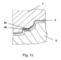
- die in der Negativform durch Unterdruck erzeugte Formhaut mit eingelegtem zweischichtigem Einleger,
- Fig. 2a
- ein fertiges Innenverkleidungsteil mit Resteinleger, und
- Fig. 2b
- eine Detailansicht des Bereichs um den Resteinleger aus
Fig. 2a . - Fig. 1a
- zeigt ein Werkzeug vor Durchführung des erfindungsgemäßen Verfahrens. Gezeigt ist hier eine Positivform 5, darüber
liegend ein Spannrahmen 4, der eine Folie 3 gespannt hält. Oberhalb des Spannrahmensist eine Negativform 7 angeordnet, die in den Figuren nicht näher dargestellten Vakuumöffnungen (diese können beispielsweise als poröse Oberflächen der Negativform verwirklicht sein) aufweist. Zwei plattenförmige Heizungen 9 sind, wie mit Doppelpfeil oberhalb der oberen Heizplatte 9 angedeutet, über den Spannrahmen bzw. die Folie verschiebbar, um somit die Folie auf eine Temperatur zwischen 160°C und 250°C, vorzugsweise zwischen 210°C und 220°C aufzuheizen.
- Fig. 1a
- a negative mold, a positive mold and a film holding tenter at the beginning of the process according to the invention,
- Fig. 1b
- a positively deformed film before stamping the insert,
- Fig. 1c
- the mold skin produced in the negative mold by negative pressure with inserted two-layer insert,
- Fig. 2a
- a finished interior trim part with rest insert, and
- Fig. 2b
- a detailed view of the area around the rest of insert
Fig. 2a , - Fig. 1a
- shows a tool before carrying out the method according to the invention. Shown here is a
positive mold 5, lying over aclamping frame 4, which holds afilm 3 stretched. Above the clamping frame, anegative mold 7 is arranged, which in the figures not shown vacuum openings (these may be realized, for example, as porous surfaces of the negative mold). Two plate-shapedheaters 9 are, as indicated by double arrow above theupper heating plate 9, slidable over the clamping frame or the film, thus the film to a temperature between 160 ° C and 250 ° C, preferably between 210 ° C and 220 ° C. heat.
Die Positivform kann zusätzlich mit hier nicht dargestellten Vakuumöffnungen zum Ansaugen und Fixieren der Folie 3 versehen sein.The positive mold may additionally be provided with vacuum openings not shown here for sucking and fixing the
Nach Aufheizen der Folie 3 und Zurückziehen der plattenförmigen Heizung 9 in die in
Nach Entnahme und Abkühlung der nun fertigen Formhaut, bei der eventuell auch noch eine Oberflächenstruktur der Negativform 7 auf die Folie bzw. Formhaut aufgeprägt wurde, wird diese aus dem Werkzeug entnommen oder auch in demselben Werkzeug hinterschäumt, hinterspritzt oder hinterprägt sowie mit einem Träger 11 versehen. Es ergibt sich nach Abziehen der Oberschicht 6a der in
In einer alternativen Variante des Verfahrens kann der Einleger auch einteilig gewählt sein bzw. es kann auch ein Einleger als "Platzhalter" eingelegt werden, der vor Fertigstellung der Formhaut durch einen endgültigen Einleger, der in der Formhaut verbleibt ersetzt wird.In an alternative variant of the method, the insert can also be selected in one piece or it can Also, an insert as a "placeholder" are inserted, which is replaced before completion of the molded skin by a final deposit that remains in the form of skin.
Ein wichtiger Aspekt der Erfindung besteht darin, dass der Einleger 6 bzw. Resteinleger 6b qualitativ hochwertig in die übrige Formhaut eingepasst ist. Hierbei ist vorteilhaft, dass der Spalt s (siehe
Der Krümmungsradius r (siehe
Bezugszeichenliste:
- 1
- Formhaut
- 2
- Innenverkleidungsteil
- 3
- Folie
- 4
- Spannrahmen
- 5
- Positivform
- 6
- Einleger:
- 6a
- Oberschicht;
- 6b
- Resteinleger
- 7
- Negativform
- 8
- Stempel
- 9
- Heizung
- r
- Krümmungsradius
- s
- Spalt
- t
- Tiefenversatz
- 1
- molded skin
- 2
- Interior trim part
- 3
- foil
- 4
- tenter
- 5
- positive mold
- 6
- depositors:
- 6a
- upper class;
- 6b
- rest depositors
- 7
- negative form
- 8th
- stamp
- 9
- heater
- r
- radius of curvature
- s
- gap
- t
- Depth offset
Claims (15)
Priority Applications (3)
| Application Number | Priority Date | Filing Date | Title |
|---|---|---|---|
| DE502008002239T DE502008002239D1 (en) | 2008-10-24 | 2008-10-24 | Method for producing a molded skin |
| AT08075849T ATE494129T1 (en) | 2008-10-24 | 2008-10-24 | METHOD FOR PRODUCING MOLDED SKIN |
| EP08075849A EP2179836B1 (en) | 2008-10-24 | 2008-10-24 | Method for the production of a plastic skin |
Applications Claiming Priority (1)
| Application Number | Priority Date | Filing Date | Title |
|---|---|---|---|
| EP08075849A EP2179836B1 (en) | 2008-10-24 | 2008-10-24 | Method for the production of a plastic skin |
Publications (2)
| Publication Number | Publication Date |
|---|---|
| EP2179836A1 true EP2179836A1 (en) | 2010-04-28 |
| EP2179836B1 EP2179836B1 (en) | 2011-01-05 |
Family
ID=40383707
Family Applications (1)
| Application Number | Title | Priority Date | Filing Date |
|---|---|---|---|
| EP08075849A Active EP2179836B1 (en) | 2008-10-24 | 2008-10-24 | Method for the production of a plastic skin |
Country Status (3)
| Country | Link |
|---|---|
| EP (1) | EP2179836B1 (en) |
| AT (1) | ATE494129T1 (en) |
| DE (1) | DE502008002239D1 (en) |
Cited By (2)
| Publication number | Priority date | Publication date | Assignee | Title |
|---|---|---|---|---|
| WO2014000863A3 (en) * | 2012-06-26 | 2014-02-20 | Rehau Ag + Co | Injection molding method for producing an injection-molded cladding element for a motor vehicle, cladding element for a motor vehicle, and array comprising an element emitting and/or receiving an electromagnetic radiation and a cladding element |
| CN112318898A (en) * | 2020-09-30 | 2021-02-05 | 航天特种材料及工艺技术研究所 | Thermal protection cabin section, RTM (resin transfer molding) method and female die thereof |
Citations (4)
| Publication number | Priority date | Publication date | Assignee | Title |
|---|---|---|---|---|
| DE4313043A1 (en) * | 1992-04-23 | 1993-10-28 | Ktx Co Ltd | Polymer moulding prodn. having with vacuum-formed patterned skin - by thermo-forming e.g. PVC and polypropylene@ foam skin, holding it in position on its porous tool and applying e.g. extruded polypropylene@ behind |
| EP1284182A2 (en) * | 2001-08-13 | 2003-02-19 | R+S Technik GmbH | Method and apparatus for forming parts with patterns on its surface |
| US20070132132A1 (en) | 2005-12-12 | 2007-06-14 | Visteon Global Technologies, Inc. | Component for a vehicle interior and a method of assembly |
| EP1864782A1 (en) * | 2006-06-09 | 2007-12-12 | Kautex Textron GmbH & Co. KG. | Method for manufacturing hollow bodies made of thermoplastic material having inserts on the inside and /or outside |
-
2008
- 2008-10-24 EP EP08075849A patent/EP2179836B1/en active Active
- 2008-10-24 DE DE502008002239T patent/DE502008002239D1/en active Active
- 2008-10-24 AT AT08075849T patent/ATE494129T1/en active
Patent Citations (4)
| Publication number | Priority date | Publication date | Assignee | Title |
|---|---|---|---|---|
| DE4313043A1 (en) * | 1992-04-23 | 1993-10-28 | Ktx Co Ltd | Polymer moulding prodn. having with vacuum-formed patterned skin - by thermo-forming e.g. PVC and polypropylene@ foam skin, holding it in position on its porous tool and applying e.g. extruded polypropylene@ behind |
| EP1284182A2 (en) * | 2001-08-13 | 2003-02-19 | R+S Technik GmbH | Method and apparatus for forming parts with patterns on its surface |
| US20070132132A1 (en) | 2005-12-12 | 2007-06-14 | Visteon Global Technologies, Inc. | Component for a vehicle interior and a method of assembly |
| EP1864782A1 (en) * | 2006-06-09 | 2007-12-12 | Kautex Textron GmbH & Co. KG. | Method for manufacturing hollow bodies made of thermoplastic material having inserts on the inside and /or outside |
Cited By (2)
| Publication number | Priority date | Publication date | Assignee | Title |
|---|---|---|---|---|
| WO2014000863A3 (en) * | 2012-06-26 | 2014-02-20 | Rehau Ag + Co | Injection molding method for producing an injection-molded cladding element for a motor vehicle, cladding element for a motor vehicle, and array comprising an element emitting and/or receiving an electromagnetic radiation and a cladding element |
| CN112318898A (en) * | 2020-09-30 | 2021-02-05 | 航天特种材料及工艺技术研究所 | Thermal protection cabin section, RTM (resin transfer molding) method and female die thereof |
Also Published As
| Publication number | Publication date |
|---|---|
| EP2179836B1 (en) | 2011-01-05 |
| DE502008002239D1 (en) | 2011-02-17 |
| ATE494129T1 (en) | 2011-01-15 |
Similar Documents
| Publication | Publication Date | Title |
|---|---|---|
| EP2588291B1 (en) | Process for producing moulded parts | |
| EP0320925A1 (en) | Method for manufacturing plastic mouldings with a decoratively embossed surface coating | |
| DE4008221A1 (en) | Moulding substrate plus decorative cover - preventing decorative area from being stretched by holding materials 1st where little deformation occurs and then pressing shaped area | |
| WO2008113446A1 (en) | Component, in particular interior trim part for a motor vehicle, and method of production | |
| DE102006024263A1 (en) | Plastic moldings made by back-injection for use as interior lining parts for cars, comprise a thin thermoplastic film with an impressed pattern on the surface, an open-structured backing and a rigid plastic support | |
| EP2184149A1 (en) | Method and device for producing a moulded part with a decorative surface | |
| EP2179836B1 (en) | Method for the production of a plastic skin | |
| DE102004034930A1 (en) | A method of molding a vehicle trim component | |
| DE102015203642A1 (en) | Method for producing a component by forming a multilayer flat semi-finished product with a soft core layer and component produced therewith | |
| DE102008037131B4 (en) | Device for producing a dimensionally stable, visible trim part for a motor vehicle, as well as a shapely and narkgebende shell for releasably connecting to a mold half of an injection molding machine | |
| EP2483049B1 (en) | Imd mold, injection molding apparatus having such an imd mold and method for producing a foil-decorated plastic part | |
| DE19949263A1 (en) | Plastic component manufacturing process uses a single tool to produce a molded product from flat sheet | |
| EP1542847A1 (en) | Method for production of an object and object produced by said method | |
| DD279636A5 (en) | METHOD FOR PRODUCING DECORATIONS OF FILMS SHAPED IN THE DEEP METERING METHOD AND DEVICE FOR CARRYING OUT SAID METHOD | |
| DE102010061944A1 (en) | Device and method for producing laminar laminated components | |
| EP1147875A2 (en) | Method for partial surface shaping of a with decorative material coated support part | |
| DE4417102A1 (en) | Thermoforming process and thermoforming device | |
| DE2606325A1 (en) | Moulding sound proofing materials for cars - by deep drawing into mould by vacuum beneath flexible rubber sheet | |
| DE102006019867B4 (en) | Process for the production of thermoformable plastic molded parts from polymer films, use of the process and dashboard for a car | |
| DE4100538A1 (en) | Prodn. of flat plastic articles - by drawing decorative film across mould, cutting off outer rim, and injecting hot polymer shot to bond to and press film against tool face | |
| DE102010034714A1 (en) | Manufacturing device for the production of a decorative part | |
| EP1044778A1 (en) | Process for making multilayered articles | |
| DE102021104122A1 (en) | Process for the production of a decorative molding | |
| DE102004025571A1 (en) | Plastic composite component for internal lining of vehicles comprises foam sheet with grained outer surface and injection molded plastic backing layer | |
| DE3010426A1 (en) | METHOD AND DEVICE FOR DEFORMING AND MAINTAINING THERMOPLASTIC PANELS |
Legal Events
| Date | Code | Title | Description |
|---|---|---|---|
| PUAI | Public reference made under article 153(3) epc to a published international application that has entered the european phase |
Free format text: ORIGINAL CODE: 0009012 |
|
| 17P | Request for examination filed |
Effective date: 20081024 |
|
| AK | Designated contracting states |
Kind code of ref document: A1 Designated state(s): AT BE BG CH CY CZ DE DK EE ES FI FR GB GR HR HU IE IS IT LI LT LU LV MC MT NL NO PL PT RO SE SI SK TR |
|
| AX | Request for extension of the european patent |
Extension state: AL BA MK RS |
|
| RTI1 | Title (correction) |
Free format text: METHOD FOR THE PRODUCTION OF A PLASTIC SKIN |
|
| GRAP | Despatch of communication of intention to grant a patent |
Free format text: ORIGINAL CODE: EPIDOSNIGR1 |
|
| GRAS | Grant fee paid |
Free format text: ORIGINAL CODE: EPIDOSNIGR3 |
|
| GRAA | (expected) grant |
Free format text: ORIGINAL CODE: 0009210 |
|
| AK | Designated contracting states |
Kind code of ref document: B1 Designated state(s): AT BE BG CH CY CZ DE DK EE ES FI FR GB GR HR HU IE IS IT LI LT LU LV MC MT NL NO PL PT RO SE SI SK TR |
|
| REG | Reference to a national code |
Ref country code: GB Ref legal event code: FG4D Free format text: NOT ENGLISH |
|
| REG | Reference to a national code |
Ref country code: CH Ref legal event code: EP |
|
| REG | Reference to a national code |
Ref country code: IE Ref legal event code: FG4D Free format text: LANGUAGE OF EP DOCUMENT: GERMAN |
|
| REF | Corresponds to: |
Ref document number: 502008002239 Country of ref document: DE Date of ref document: 20110217 Kind code of ref document: P |
|
| REG | Reference to a national code |
Ref country code: DE Ref legal event code: R096 Ref document number: 502008002239 Country of ref document: DE Effective date: 20110217 |
|
| REG | Reference to a national code |
Ref country code: NL Ref legal event code: VDEP Effective date: 20110105 |
|
| PG25 | Lapsed in a contracting state [announced via postgrant information from national office to epo] |
Ref country code: SI Free format text: LAPSE BECAUSE OF FAILURE TO SUBMIT A TRANSLATION OF THE DESCRIPTION OR TO PAY THE FEE WITHIN THE PRESCRIBED TIME-LIMIT Effective date: 20110105 |
|
| LTIE | Lt: invalidation of european patent or patent extension |
Effective date: 20110105 |
|
| PG25 | Lapsed in a contracting state [announced via postgrant information from national office to epo] |
Ref country code: IS Free format text: LAPSE BECAUSE OF FAILURE TO SUBMIT A TRANSLATION OF THE DESCRIPTION OR TO PAY THE FEE WITHIN THE PRESCRIBED TIME-LIMIT Effective date: 20110505 Ref country code: PT Free format text: LAPSE BECAUSE OF FAILURE TO SUBMIT A TRANSLATION OF THE DESCRIPTION OR TO PAY THE FEE WITHIN THE PRESCRIBED TIME-LIMIT Effective date: 20110505 Ref country code: NO Free format text: LAPSE BECAUSE OF FAILURE TO SUBMIT A TRANSLATION OF THE DESCRIPTION OR TO PAY THE FEE WITHIN THE PRESCRIBED TIME-LIMIT Effective date: 20110405 Ref country code: LT Free format text: LAPSE BECAUSE OF FAILURE TO SUBMIT A TRANSLATION OF THE DESCRIPTION OR TO PAY THE FEE WITHIN THE PRESCRIBED TIME-LIMIT Effective date: 20110105 Ref country code: SE Free format text: LAPSE BECAUSE OF FAILURE TO SUBMIT A TRANSLATION OF THE DESCRIPTION OR TO PAY THE FEE WITHIN THE PRESCRIBED TIME-LIMIT Effective date: 20110105 Ref country code: LV Free format text: LAPSE BECAUSE OF FAILURE TO SUBMIT A TRANSLATION OF THE DESCRIPTION OR TO PAY THE FEE WITHIN THE PRESCRIBED TIME-LIMIT Effective date: 20110105 Ref country code: GR Free format text: LAPSE BECAUSE OF FAILURE TO SUBMIT A TRANSLATION OF THE DESCRIPTION OR TO PAY THE FEE WITHIN THE PRESCRIBED TIME-LIMIT Effective date: 20110406 Ref country code: ES Free format text: LAPSE BECAUSE OF FAILURE TO SUBMIT A TRANSLATION OF THE DESCRIPTION OR TO PAY THE FEE WITHIN THE PRESCRIBED TIME-LIMIT Effective date: 20110416 Ref country code: HR Free format text: LAPSE BECAUSE OF FAILURE TO SUBMIT A TRANSLATION OF THE DESCRIPTION OR TO PAY THE FEE WITHIN THE PRESCRIBED TIME-LIMIT Effective date: 20110105 |
|
| REG | Reference to a national code |
Ref country code: IE Ref legal event code: FD4D |
|
| PG25 | Lapsed in a contracting state [announced via postgrant information from national office to epo] |
Ref country code: FI Free format text: LAPSE BECAUSE OF FAILURE TO SUBMIT A TRANSLATION OF THE DESCRIPTION OR TO PAY THE FEE WITHIN THE PRESCRIBED TIME-LIMIT Effective date: 20110105 Ref country code: NL Free format text: LAPSE BECAUSE OF FAILURE TO SUBMIT A TRANSLATION OF THE DESCRIPTION OR TO PAY THE FEE WITHIN THE PRESCRIBED TIME-LIMIT Effective date: 20110105 Ref country code: BG Free format text: LAPSE BECAUSE OF FAILURE TO SUBMIT A TRANSLATION OF THE DESCRIPTION OR TO PAY THE FEE WITHIN THE PRESCRIBED TIME-LIMIT Effective date: 20110405 Ref country code: CY Free format text: LAPSE BECAUSE OF FAILURE TO SUBMIT A TRANSLATION OF THE DESCRIPTION OR TO PAY THE FEE WITHIN THE PRESCRIBED TIME-LIMIT Effective date: 20110105 Ref country code: PL Free format text: LAPSE BECAUSE OF FAILURE TO SUBMIT A TRANSLATION OF THE DESCRIPTION OR TO PAY THE FEE WITHIN THE PRESCRIBED TIME-LIMIT Effective date: 20110105 |
|
| PG25 | Lapsed in a contracting state [announced via postgrant information from national office to epo] |
Ref country code: IE Free format text: LAPSE BECAUSE OF FAILURE TO SUBMIT A TRANSLATION OF THE DESCRIPTION OR TO PAY THE FEE WITHIN THE PRESCRIBED TIME-LIMIT Effective date: 20110105 Ref country code: EE Free format text: LAPSE BECAUSE OF FAILURE TO SUBMIT A TRANSLATION OF THE DESCRIPTION OR TO PAY THE FEE WITHIN THE PRESCRIBED TIME-LIMIT Effective date: 20110105 Ref country code: DK Free format text: LAPSE BECAUSE OF FAILURE TO SUBMIT A TRANSLATION OF THE DESCRIPTION OR TO PAY THE FEE WITHIN THE PRESCRIBED TIME-LIMIT Effective date: 20110105 |
|
| PLBE | No opposition filed within time limit |
Free format text: ORIGINAL CODE: 0009261 |
|
| STAA | Information on the status of an ep patent application or granted ep patent |
Free format text: STATUS: NO OPPOSITION FILED WITHIN TIME LIMIT |
|
| PG25 | Lapsed in a contracting state [announced via postgrant information from national office to epo] |
Ref country code: SK Free format text: LAPSE BECAUSE OF FAILURE TO SUBMIT A TRANSLATION OF THE DESCRIPTION OR TO PAY THE FEE WITHIN THE PRESCRIBED TIME-LIMIT Effective date: 20110105 Ref country code: CZ Free format text: LAPSE BECAUSE OF FAILURE TO SUBMIT A TRANSLATION OF THE DESCRIPTION OR TO PAY THE FEE WITHIN THE PRESCRIBED TIME-LIMIT Effective date: 20110105 Ref country code: RO Free format text: LAPSE BECAUSE OF FAILURE TO SUBMIT A TRANSLATION OF THE DESCRIPTION OR TO PAY THE FEE WITHIN THE PRESCRIBED TIME-LIMIT Effective date: 20110105 |
|
| 26N | No opposition filed |
Effective date: 20111006 |
|
| PG25 | Lapsed in a contracting state [announced via postgrant information from national office to epo] |
Ref country code: IT Free format text: LAPSE BECAUSE OF FAILURE TO SUBMIT A TRANSLATION OF THE DESCRIPTION OR TO PAY THE FEE WITHIN THE PRESCRIBED TIME-LIMIT Effective date: 20110105 |
|
| REG | Reference to a national code |
Ref country code: DE Ref legal event code: R097 Ref document number: 502008002239 Country of ref document: DE Effective date: 20111006 |
|
| BERE | Be: lapsed |
Owner name: FAURECIA INNENRAUM SYSTEME G.M.B.H. Effective date: 20111031 |
|
| PG25 | Lapsed in a contracting state [announced via postgrant information from national office to epo] |
Ref country code: MC Free format text: LAPSE BECAUSE OF NON-PAYMENT OF DUE FEES Effective date: 20111031 |
|
| PG25 | Lapsed in a contracting state [announced via postgrant information from national office to epo] |
Ref country code: BE Free format text: LAPSE BECAUSE OF NON-PAYMENT OF DUE FEES Effective date: 20111031 |
|
| PG25 | Lapsed in a contracting state [announced via postgrant information from national office to epo] |
Ref country code: MT Free format text: LAPSE BECAUSE OF FAILURE TO SUBMIT A TRANSLATION OF THE DESCRIPTION OR TO PAY THE FEE WITHIN THE PRESCRIBED TIME-LIMIT Effective date: 20110105 |
|
| PG25 | Lapsed in a contracting state [announced via postgrant information from national office to epo] |
Ref country code: LU Free format text: LAPSE BECAUSE OF NON-PAYMENT OF DUE FEES Effective date: 20111024 |
|
| REG | Reference to a national code |
Ref country code: CH Ref legal event code: PL |
|
| GBPC | Gb: european patent ceased through non-payment of renewal fee |
Effective date: 20121024 |
|
| PG25 | Lapsed in a contracting state [announced via postgrant information from national office to epo] |
Ref country code: CH Free format text: LAPSE BECAUSE OF NON-PAYMENT OF DUE FEES Effective date: 20121031 Ref country code: GB Free format text: LAPSE BECAUSE OF NON-PAYMENT OF DUE FEES Effective date: 20121024 Ref country code: LI Free format text: LAPSE BECAUSE OF NON-PAYMENT OF DUE FEES Effective date: 20121031 |
|
| PG25 | Lapsed in a contracting state [announced via postgrant information from national office to epo] |
Ref country code: TR Free format text: LAPSE BECAUSE OF FAILURE TO SUBMIT A TRANSLATION OF THE DESCRIPTION OR TO PAY THE FEE WITHIN THE PRESCRIBED TIME-LIMIT Effective date: 20110105 |
|
| PG25 | Lapsed in a contracting state [announced via postgrant information from national office to epo] |
Ref country code: HU Free format text: LAPSE BECAUSE OF FAILURE TO SUBMIT A TRANSLATION OF THE DESCRIPTION OR TO PAY THE FEE WITHIN THE PRESCRIBED TIME-LIMIT Effective date: 20110105 |
|
| REG | Reference to a national code |
Ref country code: AT Ref legal event code: MM01 Ref document number: 494129 Country of ref document: AT Kind code of ref document: T Effective date: 20131024 |
|
| PG25 | Lapsed in a contracting state [announced via postgrant information from national office to epo] |
Ref country code: AT Free format text: LAPSE BECAUSE OF NON-PAYMENT OF DUE FEES Effective date: 20131024 |
|
| REG | Reference to a national code |
Ref country code: FR Ref legal event code: PLFP Year of fee payment: 9 |
|
| REG | Reference to a national code |
Ref country code: FR Ref legal event code: PLFP Year of fee payment: 10 |
|
| REG | Reference to a national code |
Ref country code: FR Ref legal event code: PLFP Year of fee payment: 11 |
|
| PGFP | Annual fee paid to national office [announced via postgrant information from national office to epo] |
Ref country code: DE Payment date: 20220920 Year of fee payment: 15 |
|
| PGFP | Annual fee paid to national office [announced via postgrant information from national office to epo] |
Ref country code: FR Payment date: 20230920 Year of fee payment: 16 |