EP2179706B1 - Plate element for manufacturing a dental prosthesis - Google Patents
Plate element for manufacturing a dental prosthesis Download PDFInfo
- Publication number
- EP2179706B1 EP2179706B1 EP09173755A EP09173755A EP2179706B1 EP 2179706 B1 EP2179706 B1 EP 2179706B1 EP 09173755 A EP09173755 A EP 09173755A EP 09173755 A EP09173755 A EP 09173755A EP 2179706 B1 EP2179706 B1 EP 2179706B1
- Authority
- EP
- European Patent Office
- Prior art keywords
- plate
- base
- teeth
- plate according
- flat surface
- Prior art date
- Legal status (The legal status is an assumption and is not a legal conclusion. Google has not performed a legal analysis and makes no representation as to the accuracy of the status listed.)
- Not-in-force
Links
Images
Classifications
-
- A—HUMAN NECESSITIES
- A61—MEDICAL OR VETERINARY SCIENCE; HYGIENE
- A61C—DENTISTRY; APPARATUS OR METHODS FOR ORAL OR DENTAL HYGIENE
- A61C13/00—Dental prostheses; Making same
- A61C13/01—Palates or other bases or supports for the artificial teeth; Making same
Definitions
- the present invention refers to a plate element for the manufacture of a maxillary dental prosthesis. More specifically, the invention concerns a curved plate element and a method for the positioning and modelling of a malleable material capable of temporarily supporting the incisor and molar teeth according to positions and orientations that will then be fixed permanently in the prosthesis.
- the dental technician builds two so-called "bases" from resin each having a face carrying the impression of one of the two maxillary and mandibular edentulous arches.
- bases On the face of each base opposite the one having the impression one or more wax rims are applied, which simulate in position and size the dental arches and which act as a malleable and temporary support for the artificial teeth (incisor and molar teeth) that will make up the prosthesis.
- Each base provided with the relative wax rim, is inserted into the edentulous patient's mouth.
- the dentist must shape the rim with particular precision according to the distance between the edentulous arches and certain anthropometric parameters (bi-pupillary plane and Camper's sagittal plane), since the contour of the rim has a determinant effect on the orientation of the occlusal plane of the prosthesis. It is also necessary for the rim to be correctly oriented in relation to other morphological planes (e.g. with respect to the bi-pupillary plane and with respect to the so-called Camper's plane), and for it to visibly project by a few millimetres (typically by 5 mm) from the lip in the position known as "open rest".
- the dentist In order to align the rim correctly and precisely, as well as in relatively short time periods, the dentist needs to have a substantial amount of experience. In fact, in order to shape the rim to the patient, the dentist must cut away wax from the rim to remove it in the areas where it is necessary to make the rim lower, and add wax (which is heated in advance) for the points where, on the other hand, it is necessary to increase the height of the rim, until the ideal position and orientation of the rim are found in the patient's mouth. The position of the rim should also be adjusted with precision in the three dimensions of space, so that the dental prosthesis does not project too far, or is not too recessed, or otherwise misaligned.
- US-A-4 906 186 discloses a curved plate for the manufacture of a maxillary dental prosthesis, in particular a set of two curved plates arranged on a base plate and used for the manufacture of a maxillary dental prosthesis.
- the two curved plates have a general U-shaped form, delimitated by two substantially parabola-shaped contours, with an outer edge corresponding to the contour of the vestibular walls of the incisor and molar teeth of the prosthesis to be built, and an inner edge corresponding to the contour of the lingual walls of said teeth.
- the plate has a flat portion on its lower face, and the base plate defines a visible reference point corresponding to the position of the interincisive papilla.
- a primary object of the present invention is to make a device that at the same time complies with the double requirement of
- Another object of the invention is to reduce the clinical times needed to make prostheses, and in particular to reduce the number of sittings needed at the dentist, the discomfort of the patient, as well as the costs incurred by them.
- a further object of the invention is to precisely transfer the morphological data from the oral cavity of the patient to the prosthesis support, in a way practically independent from the degree of bone resorption reached by the patient.
- Yet another object of the invention is to simplify and optimise the laboratory operations for detecting the morphological data of the oral cavity of the patient, possibly also reducing the number of people involved overall in these activities.
- reference numeral 10 indicates as a unit a testing base, consisting of a rigid body of a substantially uniform thickness that provides on its upper face 11 the impression of the edentulous maxillary arch of the patient. A certain amount of material with a malleable plastic consistency is applied on the opposite lower face 12, as described later on.
- terms and expressions indicating positions and orientations such as “upper”, “lower”, “front”, “rear”, inner” and “outer” are to be interpreted with reference to the mouth of a patient, unless stated otherwise.
- the base 10 is inverted.
- a testing base of the type considered here can, for example, be made from a material that is photopolymerised after having detected the impression of the edentulous arch, as described in EP-A-2 030 585 .
- reference numeral 20 indicates a rigid or relatively rigid plate having an overall U-shape and preferably made from a plastic material, more preferably acrylic resin.
- One of the two faces of the plate 20, in this case the lower face (with reference to its intended use) features a flat surface 21, in which two blind vertical recesses 22 are formed, each situated in one of the respective left and right branches of the plate.
- the plate 20 is delimited by two substantially parabola-shaped contours: an outer edge 23, which will substantially correspond to the vestibular contour of the teeth of the prosthesis to be built, and an inner edge 24, which will substantially correspond to the lingual contour and that also features an appendix 25 the projects rearward from its front segment.
- the appendix has an apex 26 that constitutes a clearly visible reference point capable of corresponding to the position of the interincisive papilla.
- the position of the interincisive papilla generally does not vary appreciably following extractions or even in the presence of accentuated bone resorption that, as known, varies from one individual to the next.
- the outer edge or vestibular contour 23 has a segment 23a at the front with a substantially elliptical arc shape, where three reference points are highlighted, in this example in the form of small notches: a central notch 24a that defines the position of the fraenulum at an intermediate point between the vestibular surfaces of the central incisor teeth, and two notches 24b, 24c, in the positions of the reference axes of the right and left canine teeth.
- the distance "d" between the apex 26 of the appendix 25 and the central point of the outer edge 23 where the notch 24a is formed, is between 8 and 10 mm, and it is preferably 9 mm. This is the average anatomical distance that, in each individual person, separates the interincisive papilla from an ideal surface that envelopes the more vestibular walls of the upper central incisor teeth. With regard to the other dimensions of the plate 20, it should be understood that it can be shaped according to tighter or wider parabolas, according to the general morphology of the patient.
- the plate 20 is used as follows. First of all the dentist detects the position P of the interincisive papilla and highlights it with a pen on the lower face 12 of the base 10. The plate 20 is then rested on the lower face 12 of the base, making the apex 26 of the appendix 25 coincide with the previously marked position P.
- the plate 20 is then oriented angularly on the base 10 so as to align its left and right branches with the respective reliefs of the base that indicate the corresponding segments of the edentulous maxillary arch.
- the outline of the plate 20 is then traced on the lower face 12 of the base with a pen; in other words, the inner and outer edges of the plate 20 are marked on the face 12 so as to outline on the latter the borders of a curved area 13 in which all the incisor and pinless teeth will then be positioned.
- the outline thus marked defines the position of the teeth of the prosthesis with reference to the interincisive papilla: this reference ensures that the teeth of the prosthesis will be positioned in a correct and clinically acceptable manner, in the patient's mouth, no matter what the degree of bone resorption reached. In other words, the arch of the molars of the maxilla will be located with a clinically acceptable approximation in the same position as that of the original teeth.
- a strip of malleable resin 30 of plastic consistency having a height of about 1-2 cm is then applied onto the curved area 13, on the lower face 12 of the base.
- the material constituting the strip 30 is preferably a composite resin able to be photopolymerised by exposure to ultraviolet light (wavelength 350-400 nm) or halogen (wavelength 420-480 nm).
- the plate 20 is then applied underneath the strip of resin 30, so as to feature the flat surface 21 on the surface.
- the unit consisting of base 10, resin 30 and plate 20 ( figure 5 ) is then supplied to the dentist, who places it in the patient's oral cavity.
- the upper face 11 of the base featuring the impression of the edentulous arch, adapts perfectly to it, making contact with the mucosa M.
- the dentist can easily manipulate the resin and the plate with his fingers, by suitably squashing the resin, locally lifting up or lowering the plate 20 to adjust its height and inclination until the lower flat surface 21 is perfectly positioned and oriented according to certain morphological planes that will determine an ideal occlusion plane ⁇ for the prosthesis with respect to the bone structure of the patient.
- the blind holes 22 are used to determine a so-called occlusion key; the blind holes 22 create, by impression, a pair of corresponding projecting formations (not illustrated) in a strip of silicone or other malleable material applied on the jaw. Reference marks are thus obtained that will allow the dentist to manufacture a mandibular dental prosthesis that helps to define a correct occlusion with the maxillary one. Near to the blind holes 22 respective mutually facing recesses 28 are created that are used for supporting and maintaining the opposed ends 41 of a bar 40, illustrated in figures 6 and 7 , of the known type, used to determine the intermaxillary relationship on the horizontal plane defined as centric occlusion.
- the invention should not be considered to be limited to the embodiment described and illustrated here, which represents just one example embodiment of the plate, relative to the manufacture of a maxillary dental prosthesis.
- the materials selected for the plate, as well as its thickness and the width of the elliptical and parabolic arcs that define its edges can vary according to requirements.
- certain constructive details can also be modified.
- the point of the plate that defines the position of the interincisive papilla can be made to be defined by a portion having a different shape to the appendix indicated here with 25.
Abstract
Description
- The present invention refers to a plate element for the manufacture of a maxillary dental prosthesis. More specifically, the invention concerns a curved plate element and a method for the positioning and modelling of a malleable material capable of temporarily supporting the incisor and molar teeth according to positions and orientations that will then be fixed permanently in the prosthesis.
- According to one of the most common methods used up to now to make a total prosthesis, the dental technician builds two so-called "bases" from resin each having a face carrying the impression of one of the two maxillary and mandibular edentulous arches. On the face of each base opposite the one having the impression one or more wax rims are applied, which simulate in position and size the dental arches and which act as a malleable and temporary support for the artificial teeth (incisor and molar teeth) that will make up the prosthesis. Each base, provided with the relative wax rim, is inserted into the edentulous patient's mouth. The dentist must shape the rim with particular precision according to the distance between the edentulous arches and certain anthropometric parameters (bi-pupillary plane and Camper's sagittal plane), since the contour of the rim has a determinant effect on the orientation of the occlusal plane of the prosthesis. It is also necessary for the rim to be correctly oriented in relation to other morphological planes (e.g. with respect to the bi-pupillary plane and with respect to the so-called Camper's plane), and for it to visibly project by a few millimetres (typically by 5 mm) from the lip in the position known as "open rest". In order to align the rim correctly and precisely, as well as in relatively short time periods, the dentist needs to have a substantial amount of experience. In fact, in order to shape the rim to the patient, the dentist must cut away wax from the rim to remove it in the areas where it is necessary to make the rim lower, and add wax (which is heated in advance) for the points where, on the other hand, it is necessary to increase the height of the rim, until the ideal position and orientation of the rim are found in the patient's mouth. The position of the rim should also be adjusted with precision in the three dimensions of space, so that the dental prosthesis does not project too far, or is not too recessed, or otherwise misaligned.
-
US-A-4 906 186 discloses a curved plate for the manufacture of a maxillary dental prosthesis, in particular a set of two curved plates arranged on a base plate and used for the manufacture of a maxillary dental prosthesis. Together, the two curved plates have a general U-shaped form, delimitated by two substantially parabola-shaped contours, with an outer edge corresponding to the contour of the vestibular walls of the incisor and molar teeth of the prosthesis to be built, and an inner edge corresponding to the contour of the lingual walls of said teeth. The plate has a flat portion on its lower face, and the base plate defines a visible reference point corresponding to the position of the interincisive papilla. - A primary object of the present invention is to make a device that at the same time complies with the double requirement of
- facilitating and speeding up the shaping operations of the bodies made from wax or another malleable material capable of temporarily supporting the artificial teeth, and
- drastically improving the level of precision of this work, according to the different morphological characteristics of each patient, regardless of the ability of the dentist.
- Another object of the invention is to reduce the clinical times needed to make prostheses, and in particular to reduce the number of sittings needed at the dentist, the discomfort of the patient, as well as the costs incurred by them.
- A further object of the invention is to precisely transfer the morphological data from the oral cavity of the patient to the prosthesis support, in a way practically independent from the degree of bone resorption reached by the patient.
- Yet another object of the invention is to simplify and optimise the laboratory operations for detecting the morphological data of the oral cavity of the patient, possibly also reducing the number of people involved overall in these activities.
- These and other objects and advantages, which shall be better understood hereafter, are accomplished according to the present invention by a plate element having the features defined in the attached claims 1 to 13. According to another aspect of the invention, there is proposed a method that includes the steps defined in claim 14.
- A preferred but not limiting embodiment of the invention will now be described; reference is made to the attached drawings, in which:
-
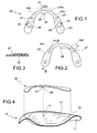
figures 1 and 2 are, respectively, a top and a bottom plan view of an embodiment of a U-shaped plate according to the invention; -
figure 3 is a cross-sectional view according to the line III-III offigure 2 ; -
figure 4 is an exploded perspective view showing the arrangement of the U-shaped plate offigures 1-3 with respect to a testing base carrying the impression of an edentulous maxillary arch; -
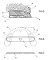
figure 5 is a schematic vertical cross-sectional view of a step of the process of the invention in which the unit comprising the plate and the base offigure 4 , joined by a resin body, is applied to the edentulous maxillary arch of a patient; and -
figures 6 and 7 are, respectively, a top view and a side view of a further Central-Bearing-Point component that can be supported by the plate of the present invention. - Referring initially to
figure 4 ,reference numeral 10 indicates as a unit a testing base, consisting of a rigid body of a substantially uniform thickness that provides on itsupper face 11 the impression of the edentulous maxillary arch of the patient. A certain amount of material with a malleable plastic consistency is applied on the oppositelower face 12, as described later on. In the present description and in the claims that follow, terms and expressions indicating positions and orientations, such as "upper", "lower", "front", "rear", inner" and "outer" are to be interpreted with reference to the mouth of a patient, unless stated otherwise. Infigure 4 thebase 10 is inverted. - A testing base of the type considered here can, for example, be made from a material that is photopolymerised after having detected the impression of the edentulous arch, as described in
EP-A-2 030 585 . - According to an embodiment of the present invention,
reference numeral 20 indicates a rigid or relatively rigid plate having an overall U-shape and preferably made from a plastic material, more preferably acrylic resin. One of the two faces of theplate 20, in this case the lower face (with reference to its intended use) features aflat surface 21, in which two blindvertical recesses 22 are formed, each situated in one of the respective left and right branches of the plate. - The
plate 20 is delimited by two substantially parabola-shaped contours: anouter edge 23, which will substantially correspond to the vestibular contour of the teeth of the prosthesis to be built, and an inner edge 24, which will substantially correspond to the lingual contour and that also features anappendix 25 the projects rearward from its front segment. The appendix has anapex 26 that constitutes a clearly visible reference point capable of corresponding to the position of the interincisive papilla. The position of the interincisive papilla generally does not vary appreciably following extractions or even in the presence of accentuated bone resorption that, as known, varies from one individual to the next. - The outer edge or
vestibular contour 23 has asegment 23a at the front with a substantially elliptical arc shape, where three reference points are highlighted, in this example in the form of small notches: acentral notch 24a that defines the position of the fraenulum at an intermediate point between the vestibular surfaces of the central incisor teeth, and twonotches - The distance "d" between the
apex 26 of theappendix 25 and the central point of theouter edge 23 where thenotch 24a is formed, is between 8 and 10 mm, and it is preferably 9 mm. This is the average anatomical distance that, in each individual person, separates the interincisive papilla from an ideal surface that envelopes the more vestibular walls of the upper central incisor teeth. With regard to the other dimensions of theplate 20, it should be understood that it can be shaped according to tighter or wider parabolas, according to the general morphology of the patient. - The
plate 20 is used as follows. First of all the dentist detects the position P of the interincisive papilla and highlights it with a pen on thelower face 12 of thebase 10. Theplate 20 is then rested on thelower face 12 of the base, making theapex 26 of theappendix 25 coincide with the previously marked position P. - The
plate 20 is then oriented angularly on thebase 10 so as to align its left and right branches with the respective reliefs of the base that indicate the corresponding segments of the edentulous maxillary arch. The outline of theplate 20 is then traced on thelower face 12 of the base with a pen; in other words, the inner and outer edges of theplate 20 are marked on theface 12 so as to outline on the latter the borders of acurved area 13 in which all the incisor and pinless teeth will then be positioned. - It should be noted that the outline thus marked defines the position of the teeth of the prosthesis with reference to the interincisive papilla: this reference ensures that the teeth of the prosthesis will be positioned in a correct and clinically acceptable manner, in the patient's mouth, no matter what the degree of bone resorption reached. In other words, the arch of the molars of the maxilla will be located with a clinically acceptable approximation in the same position as that of the original teeth.
- A strip of
malleable resin 30 of plastic consistency having a height of about 1-2 cm is then applied onto thecurved area 13, on thelower face 12 of the base. The material constituting thestrip 30 is preferably a composite resin able to be photopolymerised by exposure to ultraviolet light (wavelength 350-400 nm) or halogen (wavelength 420-480 nm). Theplate 20 is then applied underneath the strip ofresin 30, so as to feature theflat surface 21 on the surface. - By gently pressing the
plate 20 towards thebase 10, a little bit of resin of thestrip 30 will pass through twoholes 27 or other equivalent retention means foreseen in the two branches of the plate to temporarily hold it on the base together with the resin. - The unit consisting of
base 10,resin 30 and plate 20 (figure 5 ) is then supplied to the dentist, who places it in the patient's oral cavity. Theupper face 11 of the base, featuring the impression of the edentulous arch, adapts perfectly to it, making contact with the mucosa M. The dentist can easily manipulate the resin and the plate with his fingers, by suitably squashing the resin, locally lifting up or lowering theplate 20 to adjust its height and inclination until the lowerflat surface 21 is perfectly positioned and oriented according to certain morphological planes that will determine an ideal occlusion plane π for the prosthesis with respect to the bone structure of the patient. - The subsequent steps for obtaining the prosthesis are known in the field and therefore do not need to be described.
- As will be appreciated, these adaptation operations can be completed in short time periods; thanks to the relative rigidity of the
plate 20, its lowerflat surface 21 provides a precise surface that, with the conventional method with wax rims discussed in the introductory part of the description, can only be obtained after repeated removal by cutting of the edges of the rims in the areas that are too high or bulky, and after unavoidable additions of wax (previously heated) in the areas that are too low. - Tests carried out by the Applicant demonstrate that with a
curved plate 20 having a distance "d" of 9 mm, which as stated represents the average anatomical measurement, excellent results are obtained on the majority of patients in terms of precision of positioning of the front teeth, with appreciable aesthetic advantages. - The
blind holes 22 are used to determine a so-called occlusion key; theblind holes 22 create, by impression, a pair of corresponding projecting formations (not illustrated) in a strip of silicone or other malleable material applied on the jaw. Reference marks are thus obtained that will allow the dentist to manufacture a mandibular dental prosthesis that helps to define a correct occlusion with the maxillary one. Near to theblind holes 22 respective mutually facingrecesses 28 are created that are used for supporting and maintaining theopposed ends 41 of abar 40, illustrated infigures 6 and 7 , of the known type, used to determine the intermaxillary relationship on the horizontal plane defined as centric occlusion. - The invention should not be considered to be limited to the embodiment described and illustrated here, which represents just one example embodiment of the plate, relative to the manufacture of a maxillary dental prosthesis. In addition, the materials selected for the plate, as well as its thickness and the width of the elliptical and parabolic arcs that define its edges can vary according to requirements. Finally, certain constructive details can also be modified. For example, the point of the plate that defines the position of the interincisive papilla can be made to be defined by a portion having a different shape to the appendix indicated here with 25.
Claims (14)
- A curved plate (20) for the manufacture of a maxillary dental prosthesis, which features:a generallly U-shaped form, delimiteted by two substantially parabola-shaped contours, an outer edge (23), corresponding to the contour of the vestibular walls of the incisor and molar teeth of the prosthesis to be built, and an inner edge (24), corresponding to the contour of the lingual walls of said teeth,a flat surface (21) on its lower face,a portion (25) defining a visible reference point (26) corresponding to the position of the interincisive papilla (P),and wherein the distance (d) between the reference point (26) and a central point (24a) of the outer edge (23) which indicates a position situated between the most vestibular walls of the upper central incisor teeth, is comprised between 8 and 10 mm.
- A plate according to claim 1, wherein the portion that defines the visible reference (26) is defined by the apex of an appendix (25), which extends from the inner edge (24).
- A plate according to claim 2, wherein the appendix (25) projects rearward from a front segment of the inner edge (24).
- A plate according to claim 1, wherein the distance (d) is 9 mm.
- A plate according to claim 1, wherein the outer edge (23) features an elliptical arch-shaped central front segment (23a), where three reference marks are highlighted: a central reference mark (24a) defining the position of the fraenulum at an intermediate point between the vestibular surfaces of the central incisor teeth, and two lateral reference marks (24b, 24c) in the positions of the reference axes of the right and left canine teeth.
- A plate according to claim 5, wherein the three reference marks (24a, 24b, 24c) are shaped like recessed notches.
- A plate according to any one of the previous claims, wherein two vertical recesses (22), each located in one of the respective left and right branches of the plate, are made in the lower flat surface (21).
- A plate according to claim 7, where said vertical recesses (22) are blind holes.
- A plate according to any one of the previous claims, which features at least one through hole (27) that opens on the lower flat surface (21).
- A plate according to claim 7 or 8, wherein two recesses (28), each located in one of the respective left and right branches of the plate, are near the vertical recesses (22) made in the lower flat surface (21), which recesses (28) are used for supporting and maintaining the opposed ends (41) of a bar (40).
- A plate according to claim 10, wherein said recesses (28) mutually face each other.
- A plate according to any one of the previous claims, made of a relatively rigid plastic material.
- A plate according to claim 12, made of acrylic resin.
- A method for the positioning and modelling of a malleable material capable of temporarily supporting the molar teeth according to given positions and orientations, comprising the steps of:providing a testing base (10) made up of a rigid body of a substantially uniform thickness which features on its upper face (11) the impression of the edentulous maxillary arch of a patient;providing a curved plate (20) according to any one of claims from 1 to 13;detecting the position (P) of the interincisive papilla and highlighting it with a reference mark (P) on the lower face (12) of the base (10);laying the plate (20) on the lower face (12) of the base (10), making the visible reference point (26) of the plate (20) coincide with the reference mark of the position (P) of the interincisive papilla on the base (10);orienting the plate (20) on the base (10) so as to align the left and right branches of the curved plate (20) with respective reliefs of the base which indicate corresponding segments of the edentulous maxillary arch;tracing on the lower face (12) of the base (10) at least a portion of the inner and outer edges (23, 24) of the plate (20), so as to outline on the base (10) the borders of a curved area (13) within which the incisor and molar teeth will then be positioned;applying on the curved area (13) a strip of malleable material (30);applying the plate (20) under the strip of malleable material (30), so as to feature the lower flat surface (21) on the surface,placing the unit made up of the base (10), with the plate (20) and the malleable material (30) interposed between the base (10) and the plate (20) in the patient's mouth, by laying the upper face (11) of the base (10) against the mucosa which coats the edentulous maxillary arch;manipulating the malleable material (30) and/or lifting up, lowering or tilting the plate (20) so as to adjust the height and the inclination of the lower flat surface (21) according to a desired occlusion plane (π).
Applications Claiming Priority (1)
| Application Number | Priority Date | Filing Date | Title |
|---|---|---|---|
| ITTO2008A000780A IT1394129B1 (en) | 2008-10-23 | 2008-10-23 | PLATE ELEMENT FOR THE MANUFACTURE OF A DENTAL PROSTHESIS |
Publications (2)
| Publication Number | Publication Date |
|---|---|
| EP2179706A1 EP2179706A1 (en) | 2010-04-28 |
| EP2179706B1 true EP2179706B1 (en) | 2011-11-09 |
Family
ID=41119978
Family Applications (1)
| Application Number | Title | Priority Date | Filing Date |
|---|---|---|---|
| EP09173755A Not-in-force EP2179706B1 (en) | 2008-10-23 | 2009-10-22 | Plate element for manufacturing a dental prosthesis |
Country Status (5)
| Country | Link |
|---|---|
| US (1) | US20100105007A1 (en) |
| EP (1) | EP2179706B1 (en) |
| AT (1) | ATE532479T1 (en) |
| ES (1) | ES2374491T3 (en) |
| IT (1) | IT1394129B1 (en) |
Families Citing this family (2)
| Publication number | Priority date | Publication date | Assignee | Title |
|---|---|---|---|---|
| CN107088100B (en) * | 2017-06-16 | 2022-04-15 | 温州医科大学附属口腔医院 | Multifunctional oral cavity model surveying and mapping device |
| CN107115155B (en) * | 2017-06-16 | 2022-07-15 | 温州医科大学附属口腔医院 | Method for accurately describing basic bone arch line and dental arch curve |
Family Cites Families (3)
| Publication number | Priority date | Publication date | Assignee | Title |
|---|---|---|---|---|
| US4906186A (en) * | 1988-10-31 | 1990-03-06 | France Jr Stanley L | Template for setting artificial teeth in a denture |
| FR2684541B1 (en) * | 1991-12-05 | 1994-03-18 | Andre Cottard | DENTAL PROSTHESIS SUPPORT. |
| DE4306147A1 (en) * | 1993-02-27 | 1994-09-01 | Hans Peter Nell | Mounting device |
-
2008
- 2008-10-23 IT ITTO2008A000780A patent/IT1394129B1/en active
-
2009
- 2009-10-22 EP EP09173755A patent/EP2179706B1/en not_active Not-in-force
- 2009-10-22 ES ES09173755T patent/ES2374491T3/en active Active
- 2009-10-22 AT AT09173755T patent/ATE532479T1/en active
- 2009-10-22 US US12/603,997 patent/US20100105007A1/en not_active Abandoned
Also Published As
| Publication number | Publication date |
|---|---|
| IT1394129B1 (en) | 2012-05-25 |
| EP2179706A1 (en) | 2010-04-28 |
| ES2374491T3 (en) | 2012-02-17 |
| ITTO20080780A1 (en) | 2010-04-24 |
| US20100105007A1 (en) | 2010-04-29 |
| ATE532479T1 (en) | 2011-11-15 |
Similar Documents
| Publication | Publication Date | Title |
|---|---|---|
| US20230240810A1 (en) | Methods of separating occlusal surfaces with repositioning jaw elements | |
| US20230263599A1 (en) | Dental appliance with repositioning jaw elements | |
| EP3791824B1 (en) | Method for displaying repositioning jaw elements | |
| RU2510252C2 (en) | Prosthetic dentures, dental arches and methods for making them | |
| US11284976B2 (en) | Artificial teeth set including mandibular coupled artificial teeth having an arch shape and maxillary coupled artificial teeth having an arch shape | |
| US10610336B2 (en) | Tray appliance system for making a dental prosthesis | |
| JP6959662B2 (en) | Alignment jig for reference denture, denture making kit, and denture making method using these | |
| US20140154644A1 (en) | Method and apparatus for preparing denture | |
| EP2179706B1 (en) | Plate element for manufacturing a dental prosthesis | |
| JP2018196535A (en) | Standard denture base, standard denture, partial denture making kit and partial denture making method | |
| JP2009106686A (en) | Wax denture production method, and standard counter-die for artificial dentition and counter-die for determining occlusion fitting position for use in the method | |
| JP4291799B2 (en) | Artificial tooth arrangement device | |
| CN105407831A (en) | Orthodontic aligners | |
| WO2017093864A1 (en) | Dental appliances with repositioning jaw elements | |
| JP3068640U (en) | Simple front teeth, simple molars | |
| JP2020069128A (en) | Measurement device for detecting state of resorbing alveolar ridge on work cast and method therefor | |
| Wankhade et al. | Use of Broadrick flag in prosthodontic management for single complete denture: a case report | |
| JP2017046727A (en) | Maxilla reference denture base, maxilla reference denture, denture fabrication kit, and denture fabrication method using the same | |
| JP2017046726A (en) | No palate upper jaw standard denture base, no palate upper jaw standard denture, denture preparation kit and preparation method of denture using the same |
Legal Events
| Date | Code | Title | Description |
|---|---|---|---|
| PUAI | Public reference made under article 153(3) epc to a published international application that has entered the european phase |
Free format text: ORIGINAL CODE: 0009012 |
|
| AK | Designated contracting states |
Kind code of ref document: A1 Designated state(s): AT BE BG CH CY CZ DE DK EE ES FI FR GB GR HR HU IE IS IT LI LT LU LV MC MK MT NL NO PL PT RO SE SI SK SM TR |
|
| AX | Request for extension of the european patent |
Extension state: AL BA RS |
|
| 17P | Request for examination filed |
Effective date: 20101020 |
|
| REG | Reference to a national code |
Ref country code: DE Ref legal event code: R079 Ref document number: 602009003578 Country of ref document: DE Free format text: PREVIOUS MAIN CLASS: A61C0013000000 Ipc: A61C0013010000 |
|
| GRAP | Despatch of communication of intention to grant a patent |
Free format text: ORIGINAL CODE: EPIDOSNIGR1 |
|
| RIC1 | Information provided on ipc code assigned before grant |
Ipc: A61C 13/01 20060101AFI20110426BHEP |
|
| GRAS | Grant fee paid |
Free format text: ORIGINAL CODE: EPIDOSNIGR3 |
|
| GRAA | (expected) grant |
Free format text: ORIGINAL CODE: 0009210 |
|
| AK | Designated contracting states |
Kind code of ref document: B1 Designated state(s): AT BE BG CH CY CZ DE DK EE ES FI FR GB GR HR HU IE IS IT LI LT LU LV MC MK MT NL NO PL PT RO SE SI SK SM TR |
|
| REG | Reference to a national code |
Ref country code: GB Ref legal event code: FG4D |
|
| REG | Reference to a national code |
Ref country code: CH Ref legal event code: EP Ref country code: CH Ref legal event code: NV Representative=s name: JACOBACCI & PARTNERS S.P.A. |
|
| REG | Reference to a national code |
Ref country code: IE Ref legal event code: FG4D |
|
| REG | Reference to a national code |
Ref country code: DE Ref legal event code: R096 Ref document number: 602009003578 Country of ref document: DE Effective date: 20120119 |
|
| REG | Reference to a national code |
Ref country code: ES Ref legal event code: FG2A Ref document number: 2374491 Country of ref document: ES Kind code of ref document: T3 Effective date: 20120217 |
|
| REG | Reference to a national code |
Ref country code: NL Ref legal event code: VDEP Effective date: 20111109 |
|
| LTIE | Lt: invalidation of european patent or patent extension |
Effective date: 20111109 |
|
| PG25 | Lapsed in a contracting state [announced via postgrant information from national office to epo] |
Ref country code: IS Free format text: LAPSE BECAUSE OF FAILURE TO SUBMIT A TRANSLATION OF THE DESCRIPTION OR TO PAY THE FEE WITHIN THE PRESCRIBED TIME-LIMIT Effective date: 20120309 Ref country code: NO Free format text: LAPSE BECAUSE OF FAILURE TO SUBMIT A TRANSLATION OF THE DESCRIPTION OR TO PAY THE FEE WITHIN THE PRESCRIBED TIME-LIMIT Effective date: 20120209 Ref country code: LT Free format text: LAPSE BECAUSE OF FAILURE TO SUBMIT A TRANSLATION OF THE DESCRIPTION OR TO PAY THE FEE WITHIN THE PRESCRIBED TIME-LIMIT Effective date: 20111109 |
|
| PG25 | Lapsed in a contracting state [announced via postgrant information from national office to epo] |
Ref country code: GR Free format text: LAPSE BECAUSE OF FAILURE TO SUBMIT A TRANSLATION OF THE DESCRIPTION OR TO PAY THE FEE WITHIN THE PRESCRIBED TIME-LIMIT Effective date: 20120210 Ref country code: NL Free format text: LAPSE BECAUSE OF FAILURE TO SUBMIT A TRANSLATION OF THE DESCRIPTION OR TO PAY THE FEE WITHIN THE PRESCRIBED TIME-LIMIT Effective date: 20111109 Ref country code: BE Free format text: LAPSE BECAUSE OF FAILURE TO SUBMIT A TRANSLATION OF THE DESCRIPTION OR TO PAY THE FEE WITHIN THE PRESCRIBED TIME-LIMIT Effective date: 20111109 Ref country code: HR Free format text: LAPSE BECAUSE OF FAILURE TO SUBMIT A TRANSLATION OF THE DESCRIPTION OR TO PAY THE FEE WITHIN THE PRESCRIBED TIME-LIMIT Effective date: 20111109 Ref country code: SE Free format text: LAPSE BECAUSE OF FAILURE TO SUBMIT A TRANSLATION OF THE DESCRIPTION OR TO PAY THE FEE WITHIN THE PRESCRIBED TIME-LIMIT Effective date: 20111109 Ref country code: LV Free format text: LAPSE BECAUSE OF FAILURE TO SUBMIT A TRANSLATION OF THE DESCRIPTION OR TO PAY THE FEE WITHIN THE PRESCRIBED TIME-LIMIT Effective date: 20111109 Ref country code: PT Free format text: LAPSE BECAUSE OF FAILURE TO SUBMIT A TRANSLATION OF THE DESCRIPTION OR TO PAY THE FEE WITHIN THE PRESCRIBED TIME-LIMIT Effective date: 20120309 Ref country code: SI Free format text: LAPSE BECAUSE OF FAILURE TO SUBMIT A TRANSLATION OF THE DESCRIPTION OR TO PAY THE FEE WITHIN THE PRESCRIBED TIME-LIMIT Effective date: 20111109 Ref country code: PL Free format text: LAPSE BECAUSE OF FAILURE TO SUBMIT A TRANSLATION OF THE DESCRIPTION OR TO PAY THE FEE WITHIN THE PRESCRIBED TIME-LIMIT Effective date: 20111109 |
|
| PG25 | Lapsed in a contracting state [announced via postgrant information from national office to epo] |
Ref country code: CY Free format text: LAPSE BECAUSE OF FAILURE TO SUBMIT A TRANSLATION OF THE DESCRIPTION OR TO PAY THE FEE WITHIN THE PRESCRIBED TIME-LIMIT Effective date: 20111109 |
|
| PG25 | Lapsed in a contracting state [announced via postgrant information from national office to epo] |
Ref country code: BG Free format text: LAPSE BECAUSE OF FAILURE TO SUBMIT A TRANSLATION OF THE DESCRIPTION OR TO PAY THE FEE WITHIN THE PRESCRIBED TIME-LIMIT Effective date: 20120209 Ref country code: SK Free format text: LAPSE BECAUSE OF FAILURE TO SUBMIT A TRANSLATION OF THE DESCRIPTION OR TO PAY THE FEE WITHIN THE PRESCRIBED TIME-LIMIT Effective date: 20111109 Ref country code: DK Free format text: LAPSE BECAUSE OF FAILURE TO SUBMIT A TRANSLATION OF THE DESCRIPTION OR TO PAY THE FEE WITHIN THE PRESCRIBED TIME-LIMIT Effective date: 20111109 Ref country code: EE Free format text: LAPSE BECAUSE OF FAILURE TO SUBMIT A TRANSLATION OF THE DESCRIPTION OR TO PAY THE FEE WITHIN THE PRESCRIBED TIME-LIMIT Effective date: 20111109 |
|
| PG25 | Lapsed in a contracting state [announced via postgrant information from national office to epo] |
Ref country code: RO Free format text: LAPSE BECAUSE OF FAILURE TO SUBMIT A TRANSLATION OF THE DESCRIPTION OR TO PAY THE FEE WITHIN THE PRESCRIBED TIME-LIMIT Effective date: 20111109 |
|
| PLBE | No opposition filed within time limit |
Free format text: ORIGINAL CODE: 0009261 |
|
| STAA | Information on the status of an ep patent application or granted ep patent |
Free format text: STATUS: NO OPPOSITION FILED WITHIN TIME LIMIT |
|
| PGFP | Annual fee paid to national office [announced via postgrant information from national office to epo] |
Ref country code: IT Payment date: 20120630 Year of fee payment: 4 |
|
| 26N | No opposition filed |
Effective date: 20120810 |
|
| REG | Reference to a national code |
Ref country code: DE Ref legal event code: R097 Ref document number: 602009003578 Country of ref document: DE Effective date: 20120810 |
|
| PG25 | Lapsed in a contracting state [announced via postgrant information from national office to epo] |
Ref country code: MC Free format text: LAPSE BECAUSE OF NON-PAYMENT OF DUE FEES Effective date: 20121031 |
|
| PG25 | Lapsed in a contracting state [announced via postgrant information from national office to epo] |
Ref country code: FI Free format text: LAPSE BECAUSE OF FAILURE TO SUBMIT A TRANSLATION OF THE DESCRIPTION OR TO PAY THE FEE WITHIN THE PRESCRIBED TIME-LIMIT Effective date: 20111109 |
|
| REG | Reference to a national code |
Ref country code: IE Ref legal event code: MM4A |
|
| REG | Reference to a national code |
Ref country code: FR Ref legal event code: ST Effective date: 20130628 |
|
| PG25 | Lapsed in a contracting state [announced via postgrant information from national office to epo] |
Ref country code: CZ Free format text: LAPSE BECAUSE OF NON-PAYMENT OF DUE FEES Effective date: 20121022 Ref country code: IE Free format text: LAPSE BECAUSE OF NON-PAYMENT OF DUE FEES Effective date: 20121022 Ref country code: DE Free format text: LAPSE BECAUSE OF NON-PAYMENT OF DUE FEES Effective date: 20130501 |
|
| REG | Reference to a national code |
Ref country code: DE Ref legal event code: R119 Ref document number: 602009003578 Country of ref document: DE Effective date: 20130501 |
|
| PG25 | Lapsed in a contracting state [announced via postgrant information from national office to epo] |
Ref country code: FR Free format text: LAPSE BECAUSE OF NON-PAYMENT OF DUE FEES Effective date: 20121031 |
|
| PG25 | Lapsed in a contracting state [announced via postgrant information from national office to epo] |
Ref country code: MT Free format text: LAPSE BECAUSE OF FAILURE TO SUBMIT A TRANSLATION OF THE DESCRIPTION OR TO PAY THE FEE WITHIN THE PRESCRIBED TIME-LIMIT Effective date: 20111109 |
|
| REG | Reference to a national code |
Ref country code: ES Ref legal event code: FD2A Effective date: 20140408 |
|
| PG25 | Lapsed in a contracting state [announced via postgrant information from national office to epo] |
Ref country code: TR Free format text: LAPSE BECAUSE OF FAILURE TO SUBMIT A TRANSLATION OF THE DESCRIPTION OR TO PAY THE FEE WITHIN THE PRESCRIBED TIME-LIMIT Effective date: 20111109 |
|
| PG25 | Lapsed in a contracting state [announced via postgrant information from national office to epo] |
Ref country code: LU Free format text: LAPSE BECAUSE OF NON-PAYMENT OF DUE FEES Effective date: 20121022 Ref country code: SM Free format text: LAPSE BECAUSE OF FAILURE TO SUBMIT A TRANSLATION OF THE DESCRIPTION OR TO PAY THE FEE WITHIN THE PRESCRIBED TIME-LIMIT Effective date: 20111109 Ref country code: ES Free format text: LAPSE BECAUSE OF NON-PAYMENT OF DUE FEES Effective date: 20121023 |
|
| REG | Reference to a national code |
Ref country code: CH Ref legal event code: PL |
|
| GBPC | Gb: european patent ceased through non-payment of renewal fee |
Effective date: 20131022 |
|
| PG25 | Lapsed in a contracting state [announced via postgrant information from national office to epo] |
Ref country code: GB Free format text: LAPSE BECAUSE OF NON-PAYMENT OF DUE FEES Effective date: 20131022 Ref country code: HU Free format text: LAPSE BECAUSE OF FAILURE TO SUBMIT A TRANSLATION OF THE DESCRIPTION OR TO PAY THE FEE WITHIN THE PRESCRIBED TIME-LIMIT Effective date: 20091022 Ref country code: LI Free format text: LAPSE BECAUSE OF NON-PAYMENT OF DUE FEES Effective date: 20131031 Ref country code: CH Free format text: LAPSE BECAUSE OF NON-PAYMENT OF DUE FEES Effective date: 20131031 |
|
| PG25 | Lapsed in a contracting state [announced via postgrant information from national office to epo] |
Ref country code: IT Free format text: LAPSE BECAUSE OF NON-PAYMENT OF DUE FEES Effective date: 20131022 |
|
| PG25 | Lapsed in a contracting state [announced via postgrant information from national office to epo] |
Ref country code: MK Free format text: LAPSE BECAUSE OF FAILURE TO SUBMIT A TRANSLATION OF THE DESCRIPTION OR TO PAY THE FEE WITHIN THE PRESCRIBED TIME-LIMIT Effective date: 20111109 |
|
| REG | Reference to a national code |
Ref country code: AT Ref legal event code: MM01 Ref document number: 532479 Country of ref document: AT Kind code of ref document: T Effective date: 20141022 |
|
| PG25 | Lapsed in a contracting state [announced via postgrant information from national office to epo] |
Ref country code: AT Free format text: LAPSE BECAUSE OF NON-PAYMENT OF DUE FEES Effective date: 20141022 |