EP2179705B1 - Capsule et procédé de distribution d'un produit - Google Patents
Capsule et procédé de distribution d'un produit Download PDFInfo
- Publication number
- EP2179705B1 EP2179705B1 EP09173547A EP09173547A EP2179705B1 EP 2179705 B1 EP2179705 B1 EP 2179705B1 EP 09173547 A EP09173547 A EP 09173547A EP 09173547 A EP09173547 A EP 09173547A EP 2179705 B1 EP2179705 B1 EP 2179705B1
- Authority
- EP
- European Patent Office
- Prior art keywords
- product
- wall
- chamber
- capsule
- piston
- Prior art date
- Legal status (The legal status is an assumption and is not a legal conclusion. Google has not performed a legal analysis and makes no representation as to the accuracy of the status listed.)
- Not-in-force
Links
- 239000002775 capsule Substances 0.000 title claims abstract description 76
- 238000000034 method Methods 0.000 title claims abstract description 9
- 235000011837 pasties Nutrition 0.000 claims abstract description 15
- 230000000295 complement effect Effects 0.000 claims description 3
- 230000003213 activating effect Effects 0.000 claims 1
- 238000009826 distribution Methods 0.000 description 21
- 238000002156 mixing Methods 0.000 description 12
- 238000002347 injection Methods 0.000 description 4
- 239000007924 injection Substances 0.000 description 4
- 239000007788 liquid Substances 0.000 description 4
- 238000004519 manufacturing process Methods 0.000 description 4
- 208000031968 Cadaver Diseases 0.000 description 3
- 238000001746 injection moulding Methods 0.000 description 3
- 239000000203 mixture Substances 0.000 description 3
- 230000000694 effects Effects 0.000 description 2
- 239000000843 powder Substances 0.000 description 2
- 229920002994 synthetic fiber Polymers 0.000 description 2
- 238000003805 vibration mixing Methods 0.000 description 2
- 230000002087 whitening effect Effects 0.000 description 2
- 229910000831 Steel Inorganic materials 0.000 description 1
- 230000015572 biosynthetic process Effects 0.000 description 1
- 239000004568 cement Substances 0.000 description 1
- 238000005520 cutting process Methods 0.000 description 1
- 238000006073 displacement reaction Methods 0.000 description 1
- 238000004806 packaging method and process Methods 0.000 description 1
- 239000011505 plaster Substances 0.000 description 1
- 239000011347 resin Substances 0.000 description 1
- 229920005989 resin Polymers 0.000 description 1
- 238000005070 sampling Methods 0.000 description 1
- 238000007789 sealing Methods 0.000 description 1
- 239000010959 steel Substances 0.000 description 1
- 238000003756 stirring Methods 0.000 description 1
Images


Classifications
-
- A—HUMAN NECESSITIES
- A61—MEDICAL OR VETERINARY SCIENCE; HYGIENE
- A61C—DENTISTRY; APPARATUS OR METHODS FOR ORAL OR DENTAL HYGIENE
- A61C5/00—Filling or capping teeth
- A61C5/60—Devices specially adapted for pressing or mixing capping or filling materials, e.g. amalgam presses
- A61C5/66—Capsules for filling material
-
- A—HUMAN NECESSITIES
- A61—MEDICAL OR VETERINARY SCIENCE; HYGIENE
- A61C—DENTISTRY; APPARATUS OR METHODS FOR ORAL OR DENTAL HYGIENE
- A61C5/00—Filling or capping teeth
- A61C5/60—Devices specially adapted for pressing or mixing capping or filling materials, e.g. amalgam presses
-
- A—HUMAN NECESSITIES
- A61—MEDICAL OR VETERINARY SCIENCE; HYGIENE
- A61C—DENTISTRY; APPARATUS OR METHODS FOR ORAL OR DENTAL HYGIENE
- A61C5/00—Filling or capping teeth
- A61C5/60—Devices specially adapted for pressing or mixing capping or filling materials, e.g. amalgam presses
- A61C5/62—Applicators, e.g. syringes or guns
Definitions
- the present invention relates to a capsule for dispensing a product, in particular a pasty product, as well as a method for dispensing a product.
- the piston is slidable in the mixing chamber and is equipped with a pusher which is capable of causing, in due course, the flow of the liquid component from the piston to the mixing chamber through an opening of the initially closed piston.
- a pusher which is capable of causing, in due course, the flow of the liquid component from the piston to the mixing chamber through an opening of the initially closed piston.
- the mixing capsule described in US-2003176834 is pre-filled, with predefined proportions of the various components of the product to be dispensed. Therefore, it is not possible, with such a capsule, to modulate the properties of the product to be dispensed, in particular its viscosity.
- this known capsule has a complex structure that involves several parts, assembled to maintain the different components of the product separated from each other before using the capsule. However, the assembly of these different parts requires a high time and cost of manufacture of the capsule.
- EP-A-0 225 265 discloses a syringe for the injection of pasty product and which comprises a sampling tube set up in a main body. A piston equipped with a push-button is inserted into an orifice a gripping ring mounted at the end of the gripping tube. This syringe has many parts and is relatively complex to manufacture.
- the invention intends to remedy more particularly by proposing a product dispensing capsule whose manufacturing cost is limited and which makes it possible to modulate the properties of the product to be dispensed.
- the subject of the invention is a capsule for dispensing a product, in particular a pasty product, comprising a body which defines an interior chamber for receiving the product and is provided with a product dispensing opening, a piston being able to slide in the chamber along an internal wall of the chamber, characterized in that the body comprises a first and a second part able to fit one with respect to the other, the first part comprising the piston and a first portion of the inner wall of the chamber, the piston and the first wall portion being connected to each other by breakable means, while the second portion comprises a second portion of the wall internal, the first and second wall portions forming the inner wall of the chamber in nested configuration of the first and second parts.
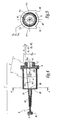
- the dispensing capsule 1 shown in the figures is intended for dispensing a pasty bi-component product 2, for example a tooth whitening paste, the components 21 and 23 of which are initially packaged separately.
- the capsule 1 comprises a body 3, which defines an interior chamber 4 for receiving the product 2.
- the body 3 comprises a drawer 7 and a casing 9 adapted to be engaged one inside the other in the direction of an axis of fitting X-X ', which is a common longitudinal axis to the drawer 7 and to the envelope 9.
- the slider 7 of the body 3 comprises a portion 71 of circular cylindrical wall, centered on an axis X 7 -X 7 ', and a piston 5 connected to one end 71 A of the wall portion 71 by means of breakable bridges 6.
- the piston 5 comprises a disk 51 which has a diameter d 51 equal to the inner diameter d 71 of the cylindrical wall portion 71.
- a front face 51B of the disk 51 is connected, by means of the bridges 6, to the end 71A of the wall portion 71, so that the disc 51 is centered on the X axis 7 -X 7 '-
- a rear face 51A of the disc 51, opposite the face 51B, carries a ring 53 for receiving a tool for the application of a thrust force on the face 51 A.
- the wall portion 71 is a portion of cylindrical wall sectioned or decalcified, according to a plane ⁇ inclined relative to the axis X 7 -X 7 'of the cylinder.
- the angle ⁇ of inclination of the plane ⁇ with respect to the axis X 7 -X 7 ' is of the order of 5 °.
- the wall portion 71 cut along the plane ⁇ thus defines an internal volume 74, which opens not only at the end 71B of the wall portion 71 opposite the piston 5 but also at a longitudinal opening 75.
- L 75 extends transversely with respect to the piston 5 and is laterally bordered by two longitudinal free edges 711 of the wall portion 71.
- the plane ⁇ is inclined with respect to the axis X 7 -X 7 'so as to move away from the axis X 7 -X 7 ' towards the piston 5. Due to this specific inclination of the plane ⁇ , the longitudinal opening 75 of the slide 7 is flared, that is to say has a spacing e between the free edges 711 which increases, since the end 71 A towards the end 71B of the wall portion 71.
- the angle ⁇ of inclination of the plane ⁇ with respect to the axis X 7 -X 7 ' is advantageously between approximately 1 ° and 45 °.
- the envelope 9 of the body 3 comprises a tubular wall 93 of circular section centered on an axis X 9 -X 9 ', which defines an interior volume 94 of the envelope.
- the volume 94 is closed, at one end 93B of the tubular wall 93, by an end wall 95.
- the end wall 95 is pierced with a product dispensing opening 97, from which extends a dispensing channel 98 formed within a product application nozzle 92.
- the nozzle 92 is integral with the end wall 95.
- the capsule 1 also comprises a stem 8 for closing the distribution channel 98.
- the rod 8 is able to partially fill the channel 98 and is provided with a gripping head 81.
- the tubular wall 93 of the casing 9 internally comprises a portion 91 of cylindrical wall with a circular section, also centered on the axis X 9 -X 9 ', which protrudes with respect to the tubular wall 93 in the internal volume 94.
- the wall portion 91 of the casing 9 and the wall portion 71 of the drawer 7 are designed to form together, in the fitted configuration of the drawer 7 in the casing 9, an inner wall 41 of the chamber 4 of the body 3
- the wall portions 71 and 91 are two complementary portions of the inner wall 41 cut along the plane ⁇ .
- the wall portion 91 is a portion of cylindrical wall sectioned along the plane ⁇ , which is inclined relative to the axis X 9 -X 9 'so as to approach the axis X 9 -X 9 ' in the direction of the end wall 95, and has an inner diameter d 91 equal to the inside diameter d 71 of the wall portion 71.
- the wall portion 91 is thus adapted to close the longitudinal opening 75 of the drawer 7 by the supported by longitudinal free edges 911 of the wall portion 91 against the free edges 711 of the wall portion 71, as shown in the section of the figure 5 .
- the slide 7 is able to slide into the casing 9 by sliding in the internal volume 94 of the tubular wall 93 when the axes X 7 -X 7 'and X 9 -X 9 ' are merged along the axis d '.
- the free edges 711 and 911 bear in pairs so that the internal wall 41 of the chamber 4, formed by the wall portions 71 and 91, is substantially continuous.
- the inner wall 41 is cylindrical with a circular section centered on the fitting axis XX 'and has an inside diameter d 41 equal to the inside diameter d 71 or 91 of the wall portions 71 and 91, that is to say to the outside diameter d 51 of the disc 51 of the piston 5.
- the piston 5 is able to slide in a sealed manner in the chamber 4, along the wall internal 41, in the direction of the axis of fitting X-X '.
- the piston 5 is in sliding and sealing contact with the inner wall 41 of the chamber 4 in the fitted configuration of the slide 7 in the casing 9.
- the chamber 4 of the body 3 is sealed in the configuration. fitted with the slide 7 and the casing 9 with the dispensing channel 98 closed by means of the rod 8.
- the piston 5 can be slidably moved in the chamber 4, along the inner wall 41 and towards the end wall 95, under the effect of a thrust force F 2 exerted on the face 51A of the disk 51.
- a thrust force F 2 may in particular be applied to the face 51 A by means of a clamp, a part movable in translation may be received in the ring 53 of the piston, so as to exert the thrust force F 2 on the face 51 A, while the envelope 9 of the body 3 is immobilized relative to a fixed part of the clamp.
- the slide 7 and the casing 9 of the body 3 are two parts molded by injection of a synthetic material.
- the slide 7 is molded in one piece, the breakable bridges 6 connecting the piston 5 and the wall portion 71 being formed directly during the injection molding.
- a method of dispensing the bi-component product 2 by means of the capsule 1 according to the invention comprises steps as described below.
- a first component 21 of the product 2 which is in the form of a powder in the example shown, is introduced into the internal volume 74 of the slide 7.
- the second component 23 of the product 2 is also introduced.
- the distribution channel 98 has previously been closed by means of the rod 8. This gives the configuration of the capsule 1 visible on the figure 6 .
- the drawer 7 is then inserted into the casing 9.
- the drawer 7 and the casing 9 are positioned in such a way that the X 7 -X 7 'and X 9 -X 9 ' axes coincide according to the fitting axis XX 'and that the free edges 711 and 911 are facing each other in pairs, the end 71B of the drawer being directed towards the end wall 95 of the envelope.
- the slide 7 is slid into the inner volume 94 of the casing 9, parallel to the fitting axis X-X '.
- This sliding can be operated manually by an operator who exerts a thrust force F 1 on the ring 53 of the piston 5, as shown in FIG.
- the fitted configuration of the drawer 7 is obtained in the envelope 9, visible on the figure 7 , in which the wall portions 71 and 91 together define the inner wall 41 of the chamber 4 of the body 3.
- the chamber 4 is waterproof.
- the capsule 1 may comprise a weight, such as a steel ball, secured to one of the spool 7 or the envelope 9.
- a weight may be fixed on the disc 51 of the drawer 7, by clipping into a notch formed of side of the face 51B of the disc 51 during the injection molding of the slide 7.
- this fixing means must allow the release of the weight in the chamber 4 during the stirring, in particular by vibration, of the capsule 1 in the fitted configuration of the slide valve 7 in the casing 9.
- the weight is able to move in the chamber 4 during mixing by vibration, which contributes to the mixture of components 21 and 23 and to the formation of a pasty product 2 homogeneous.
- the capsule 1 is advantageously provided with means preventing the closure by the weight of the opening 97 and the product distribution channel 98.
- the envelope 9 may comprise a cone for receiving the feeder, arranged in the vicinity of the dispensing aperture 97 and bordered with product passage orifices 2.
- the rod 8 is withdrawn with respect to the distribution channel 98 and the piston 5 is slidably moved in the chamber 4, after tearing the breakable bridges 6, along the inner wall 41 and in the direction of the end wall 95, so as to dispense the product 2 through the opening 97 and the distribution channel 98, as shown in FIG. figure 8 .
- a thrust force F 2 is exerted on the face 51A of the disk 51 of the piston 5.
- the force F 2 exerted on the piston 5 first causes the breaking of the bridges 6 connecting the piston 5 and the wall portion 71, then the sliding of the piston 5, disengaged from the wall portion 71, to the interior of the chamber 4 delimited by the wall portions 71 and 91.
- the thrust force F 2 can be exerted on the face 51 A by means of a not shown clamp, in accordance with the teaching of EP-A-1795146 , a part movable in translation is received in the ring 53 of the piston and exerts the thrust force F 2 on the face 51 A, while the casing 9 is immobilized relative to a fixed portion of the clamp.
- the envelope 9 is provided with tabs 99 of axial alignment of the envelope relative to the clamp.
- the dispensing capsule 1 has a simple structure. Indeed, the capsule body 3 comprises only two parts, namely the slide 7, which integrates the piston 5, and the casing 9. In a particularly advantageous manner, each component 7 or 9 constituting the capsule 1 can be obtained by injection molding of a synthetic material, which limits the manufacturing cost of the capsule.
- the structure of the capsule 1 according to the invention makes it possible to maintain the various components of a multi-component product. components separated from each other before use of the capsule.
- the drawer 7 defines a first product receiving volume 74, adapted to receive a first component
- the envelope 9 defines a second volume 94 product receiving adapted to receive a second component.
- the capsule 1 according to the invention also has the advantage of being refillable directly by the user, just before the distribution of a product. It is thus possible to adapt the relative proportions of the components of a product to be dispensed and to control the properties of this product, in particular its viscosity.
- the filling nature of the capsule 1 according to the invention also allows the user to purchase the components of the product in large quantities, which limits the cost of these components, especially in relation to their cost when packaged in small amount in conventional mixing capsules.
- the specific structure of the capsule 1 according to the invention which comprises a slide 7 whose wall 71 defines a product receiving volume 74, accessible via a transverse longitudinal opening 75 relative to the piston 5, facilitates the filling of the capsule.
- the possibility of filling the capsule by such a large lateral opening rather than by an open end of a cylindrical capsule body, as is the case with the capsules of the state of the art is advantageous for dispensing an initially pasty product, such as a pasty one-component product.
- It is indeed possible to fill the drawer 7 of the capsule by displaying the pasty product in the interior volume 74 of the drawer, for example by means of a spatula.
- the specific shape of the drawer 7 open laterally allows it also to be used as a metering element, similarly to a dosing spoon, for taking a defined amount of product, for example a powdery product, in its packaging container.
- the body 3 of a dispensing capsule according to the invention may be of any suitable shape other than cylindrical with a circular section.
- the inner wall 41 of the inner chamber 4 may in particular be of other than circular section, for example of square section, the section of the piston 5 being adapted accordingly.
- the opening 75 of the slide 7 can be defined by cutting the wall portion 71 in a plane parallel to the central axis X-X 'of the capsule, instead of a plane inclined relative to this axis.
- the opening 75 of the drawer 7 may not extend over the entire length of the drawer, but only on a portion of the wall 71.
- the slide 7 may also have a length, in the direction of the axis X 7 -X 7 ', less than the length of the casing 9 in the direction of the X axis 9 -X 9 '.
- the sliding of the slide 7 inside the casing 9 until the abutment of the end 71B of the slide against the end wall 95 of the casing can then be obtained by means of the tool, for example the clamp, which then allows the piston 5 to slide in the chamber 4.
- a dispensing capsule according to the invention may also comprise a casing 9 which does not have, in its longitudinal direction, tubular wall 93, but only the wall portion 91.
- the casing 9 may be nested relative to the slide 7, for example by clipping the wall portion 91 on the wall portion 71, or by any other appropriate means.
- the assembly of the drawer and casing parts of the body 3 of a capsule according to the invention is obtained by a relative interlocking of the parts of the body, the relative fitting of the parts of the body being a particular case of interlocking.
- a dispensing capsule according to the invention can be used for dispensing products other than bi-component products for dental applications.
- a capsule according to the invention can indeed also be used for the distribution of single-component products.
- the single-component product to be dispensed can be introduced, optionally, into the interior volume 74 of the drawer 7, into the interior volume 94 of the envelope 9 or both, before interlocking the parts 7 and 9.
- the product to be dispensed is a pasty one-component product
- a capsule according to the invention can be used for the distribution of products other than products for dental use, such as, by way of non-limiting examples, products of the coated, plaster or cement type, the dimensions of the capsule being adapted according to the application.
Landscapes
- Health & Medical Sciences (AREA)
- General Health & Medical Sciences (AREA)
- Dentistry (AREA)
- Epidemiology (AREA)
- Life Sciences & Earth Sciences (AREA)
- Animal Behavior & Ethology (AREA)
- Oral & Maxillofacial Surgery (AREA)
- Public Health (AREA)
- Veterinary Medicine (AREA)
- Medical Preparation Storing Or Oral Administration Devices (AREA)
- Dental Tools And Instruments Or Auxiliary Dental Instruments (AREA)
- Meat, Egg Or Seafood Products (AREA)
- Formation And Processing Of Food Products (AREA)
Priority Applications (1)
| Application Number | Priority Date | Filing Date | Title |
|---|---|---|---|
| PL09173547T PL2179705T3 (pl) | 2008-10-21 | 2009-10-20 | Kapsułka i sposób rozprowadzania produktu |
Applications Claiming Priority (1)
| Application Number | Priority Date | Filing Date | Title |
|---|---|---|---|
| FR0857143A FR2937313B1 (fr) | 2008-10-21 | 2008-10-21 | Capsule et procede de distribution d'un produit |
Publications (2)
| Publication Number | Publication Date |
|---|---|
| EP2179705A1 EP2179705A1 (fr) | 2010-04-28 |
| EP2179705B1 true EP2179705B1 (fr) | 2011-07-13 |
Family
ID=40678052
Family Applications (1)
| Application Number | Title | Priority Date | Filing Date |
|---|---|---|---|
| EP09173547A Not-in-force EP2179705B1 (fr) | 2008-10-21 | 2009-10-20 | Capsule et procédé de distribution d'un produit |
Country Status (5)
| Country | Link |
|---|---|
| EP (1) | EP2179705B1 (pl) |
| AT (1) | ATE515985T1 (pl) |
| ES (1) | ES2367729T3 (pl) |
| FR (1) | FR2937313B1 (pl) |
| PL (1) | PL2179705T3 (pl) |
Family Cites Families (5)
| Publication number | Priority date | Publication date | Assignee | Title |
|---|---|---|---|---|
| US3346147A (en) * | 1966-08-18 | 1967-10-10 | Brunswick Corp | Dental compound syringe |
| FR2558801B1 (fr) * | 1984-01-27 | 1986-10-03 | Oreal | Ensemble permettant de distribuer des doses d'une substance de consistance liquide ou pateuse |
| FR2590487A1 (fr) * | 1985-11-25 | 1987-05-29 | Francois Michel | Seringue pour l'injection de produits pateux destines a la prise d'empreintes dentaires, avec dispositif de remplissage incorpore |
| DE50203268D1 (de) | 2002-03-15 | 2005-07-07 | Muehlbauer Ernst Gmbh & Co Kg | Mehrkomponenten-Mischkapsel, insbesondere für Dentalzwecke |
| JP4489695B2 (ja) | 2005-12-08 | 2010-06-23 | 株式会社ジーシー | カプセル内で混合練和された歯牙修復材の押出し装置 |
-
2008
- 2008-10-21 FR FR0857143A patent/FR2937313B1/fr not_active Expired - Fee Related
-
2009
- 2009-10-20 AT AT09173547T patent/ATE515985T1/de not_active IP Right Cessation
- 2009-10-20 PL PL09173547T patent/PL2179705T3/pl unknown
- 2009-10-20 EP EP09173547A patent/EP2179705B1/fr not_active Not-in-force
- 2009-10-20 ES ES09173547T patent/ES2367729T3/es active Active
Also Published As
| Publication number | Publication date |
|---|---|
| FR2937313A1 (fr) | 2010-04-23 |
| PL2179705T3 (pl) | 2011-12-30 |
| EP2179705A1 (fr) | 2010-04-28 |
| FR2937313B1 (fr) | 2010-12-10 |
| ATE515985T1 (de) | 2011-07-15 |
| ES2367729T3 (es) | 2011-11-08 |
Similar Documents
| Publication | Publication Date | Title |
|---|---|---|
| FR2830520A1 (fr) | Dispositif pour le conditionnement separe et la distribution conjointe de deux produits | |
| FR2703333A1 (fr) | Emballage distributeur pour produit pâteux en forme de bâtonnet avec une douille externe fixe de décoration du corps . | |
| EP1917202B1 (fr) | Valve de distribution de produit fluide | |
| EP2167398B1 (fr) | Valve de distribution de produit fluide et dispositif de distribution de produit fluide comportant une telle valve | |
| FR2617809A1 (fr) | Recipient pour le conditionnement d'un produit et sa distribution dans de bonnes conditions de proprete | |
| WO2021094683A1 (fr) | Dispositif de distribution de produit fluide | |
| EP0097175B1 (fr) | Cartouche pour injecter un produit semi-pateux | |
| EP0944440A1 (fr) | Dispositif de distribution d'une matiere extrudable telle qu'une pate a usage dentaire | |
| EP2092985B1 (fr) | Flacon comprenant un tube plongeur | |
| EP2379137A1 (fr) | Dispositif d'ejection | |
| EP1189648B1 (fr) | Dispositif de distribution de produit fluide comportant une tete de distribution amelioree | |
| EP2179705B1 (fr) | Capsule et procédé de distribution d'un produit | |
| EP1673961A2 (fr) | Valve et dispositif de distribution comportant une telle valve | |
| FR2630409A3 (fr) | Procede de realisation d'un contenant plastique a fond pince et contenant plastique obtenu par ce procede | |
| EP3980350B1 (fr) | Valve pour récipient sous pression | |
| EP2090515B1 (fr) | Flacon sécable destiné à contenir un liquide | |
| WO2004013017A1 (fr) | Dispositif de pulverisation de produit fluide | |
| FR2647757A1 (fr) | Distributeur de doses predeterminees d'un produit liquide ou pateux, notamment produit alimentaire ou cosmetique | |
| FR2838357A1 (fr) | Tete de distribution et poussoir incorporant une telle tete | |
| EP0341170A1 (fr) | Procédé de fabrication d'un récipient ou tube équipé d'une pompe, outillages correspondants et récipient ou tube obtenu | |
| WO2019220062A1 (fr) | Dispositif de distribution de produit fluide | |
| FR2637512A1 (fr) | Dispositif de delivrance automatique d'un produit ou d'un objet quelconque | |
| WO2005012137A2 (fr) | Valve de distribution de produits fluides et distributeur comportant une telle valve | |
| EP0918023A1 (fr) | Dispositif pour le mélange extemporané de deux produits | |
| EP2919613B1 (fr) | Tête d'application d'un produit cosmétique, dispositif et procédé associés |
Legal Events
| Date | Code | Title | Description |
|---|---|---|---|
| PUAI | Public reference made under article 153(3) epc to a published international application that has entered the european phase |
Free format text: ORIGINAL CODE: 0009012 |
|
| AK | Designated contracting states |
Kind code of ref document: A1 Designated state(s): AT BE BG CH CY CZ DE DK EE ES FI FR GB GR HR HU IE IS IT LI LT LU LV MC MK MT NL NO PL PT RO SE SI SK SM TR |
|
| 17P | Request for examination filed |
Effective date: 20101008 |
|
| RIC1 | Information provided on ipc code assigned before grant |
Ipc: A61C 5/06 20060101AFI20101206BHEP |
|
| GRAP | Despatch of communication of intention to grant a patent |
Free format text: ORIGINAL CODE: EPIDOSNIGR1 |
|
| RIN1 | Information on inventor provided before grant (corrected) |
Inventor name: BOLLE, JEREMY Inventor name: RENARD, JEAN-YVES |
|
| GRAS | Grant fee paid |
Free format text: ORIGINAL CODE: EPIDOSNIGR3 |
|
| GRAA | (expected) grant |
Free format text: ORIGINAL CODE: 0009210 |
|
| AK | Designated contracting states |
Kind code of ref document: B1 Designated state(s): AT BE BG CH CY CZ DE DK EE ES FI FR GB GR HR HU IE IS IT LI LT LU LV MC MK MT NL NO PL PT RO SE SI SK SM TR |
|
| REG | Reference to a national code |
Ref country code: GB Ref legal event code: FG4D Free format text: NOT ENGLISH |
|
| REG | Reference to a national code |
Ref country code: CH Ref legal event code: EP |
|
| REG | Reference to a national code |
Ref country code: IE Ref legal event code: FG4D Free format text: LANGUAGE OF EP DOCUMENT: FRENCH |
|
| REG | Reference to a national code |
Ref country code: DE Ref legal event code: R096 Ref document number: 602009001789 Country of ref document: DE Effective date: 20110901 |
|
| REG | Reference to a national code |
Ref country code: RO Ref legal event code: EPE |
|
| REG | Reference to a national code |
Ref country code: CH Ref legal event code: NV Representative=s name: KIRKER & CIE S.A. |
|
| REG | Reference to a national code |
Ref country code: NL Ref legal event code: T3 |
|
| REG | Reference to a national code |
Ref country code: ES Ref legal event code: FG2A Ref document number: 2367729 Country of ref document: ES Kind code of ref document: T3 Effective date: 20111108 |
|
| REG | Reference to a national code |
Ref country code: DE Ref legal event code: R082 Ref document number: 602009001789 Country of ref document: DE Representative=s name: PFENNING MEINIG & PARTNER GBR, DE Ref country code: DE Ref legal event code: R082 Ref document number: 602009001789 Country of ref document: DE Representative=s name: PFENNING, MEINIG & PARTNER MBB PATENTANWAELTE, DE |
|
| REG | Reference to a national code |
Ref country code: PL Ref legal event code: T3 |
|
| REG | Reference to a national code |
Ref country code: AT Ref legal event code: MK05 Ref document number: 515985 Country of ref document: AT Kind code of ref document: T Effective date: 20110713 |
|
| REG | Reference to a national code |
Ref country code: HU Ref legal event code: AG4A Ref document number: E012038 Country of ref document: HU |
|
| PG25 | Lapsed in a contracting state [announced via postgrant information from national office to epo] |
Ref country code: PT Free format text: LAPSE BECAUSE OF FAILURE TO SUBMIT A TRANSLATION OF THE DESCRIPTION OR TO PAY THE FEE WITHIN THE PRESCRIBED TIME-LIMIT Effective date: 20111114 Ref country code: SE Free format text: LAPSE BECAUSE OF FAILURE TO SUBMIT A TRANSLATION OF THE DESCRIPTION OR TO PAY THE FEE WITHIN THE PRESCRIBED TIME-LIMIT Effective date: 20110713 Ref country code: IS Free format text: LAPSE BECAUSE OF FAILURE TO SUBMIT A TRANSLATION OF THE DESCRIPTION OR TO PAY THE FEE WITHIN THE PRESCRIBED TIME-LIMIT Effective date: 20111113 Ref country code: FI Free format text: LAPSE BECAUSE OF FAILURE TO SUBMIT A TRANSLATION OF THE DESCRIPTION OR TO PAY THE FEE WITHIN THE PRESCRIBED TIME-LIMIT Effective date: 20110713 Ref country code: LT Free format text: LAPSE BECAUSE OF FAILURE TO SUBMIT A TRANSLATION OF THE DESCRIPTION OR TO PAY THE FEE WITHIN THE PRESCRIBED TIME-LIMIT Effective date: 20110713 Ref country code: HR Free format text: LAPSE BECAUSE OF FAILURE TO SUBMIT A TRANSLATION OF THE DESCRIPTION OR TO PAY THE FEE WITHIN THE PRESCRIBED TIME-LIMIT Effective date: 20110713 Ref country code: NO Free format text: LAPSE BECAUSE OF FAILURE TO SUBMIT A TRANSLATION OF THE DESCRIPTION OR TO PAY THE FEE WITHIN THE PRESCRIBED TIME-LIMIT Effective date: 20111013 |
|
| REG | Reference to a national code |
Ref country code: IE Ref legal event code: FD4D |
|
| PG25 | Lapsed in a contracting state [announced via postgrant information from national office to epo] |
Ref country code: AT Free format text: LAPSE BECAUSE OF FAILURE TO SUBMIT A TRANSLATION OF THE DESCRIPTION OR TO PAY THE FEE WITHIN THE PRESCRIBED TIME-LIMIT Effective date: 20110713 Ref country code: SI Free format text: LAPSE BECAUSE OF FAILURE TO SUBMIT A TRANSLATION OF THE DESCRIPTION OR TO PAY THE FEE WITHIN THE PRESCRIBED TIME-LIMIT Effective date: 20110713 Ref country code: GR Free format text: LAPSE BECAUSE OF FAILURE TO SUBMIT A TRANSLATION OF THE DESCRIPTION OR TO PAY THE FEE WITHIN THE PRESCRIBED TIME-LIMIT Effective date: 20111014 Ref country code: LV Free format text: LAPSE BECAUSE OF FAILURE TO SUBMIT A TRANSLATION OF THE DESCRIPTION OR TO PAY THE FEE WITHIN THE PRESCRIBED TIME-LIMIT Effective date: 20110713 Ref country code: CY Free format text: LAPSE BECAUSE OF FAILURE TO SUBMIT A TRANSLATION OF THE DESCRIPTION OR TO PAY THE FEE WITHIN THE PRESCRIBED TIME-LIMIT Effective date: 20110713 |
|
| PG25 | Lapsed in a contracting state [announced via postgrant information from national office to epo] |
Ref country code: IE Free format text: LAPSE BECAUSE OF FAILURE TO SUBMIT A TRANSLATION OF THE DESCRIPTION OR TO PAY THE FEE WITHIN THE PRESCRIBED TIME-LIMIT Effective date: 20110713 Ref country code: SK Free format text: LAPSE BECAUSE OF FAILURE TO SUBMIT A TRANSLATION OF THE DESCRIPTION OR TO PAY THE FEE WITHIN THE PRESCRIBED TIME-LIMIT Effective date: 20110713 |
|
| PLBE | No opposition filed within time limit |
Free format text: ORIGINAL CODE: 0009261 |
|
| STAA | Information on the status of an ep patent application or granted ep patent |
Free format text: STATUS: NO OPPOSITION FILED WITHIN TIME LIMIT |
|
| PG25 | Lapsed in a contracting state [announced via postgrant information from national office to epo] |
Ref country code: MC Free format text: LAPSE BECAUSE OF NON-PAYMENT OF DUE FEES Effective date: 20111031 Ref country code: EE Free format text: LAPSE BECAUSE OF FAILURE TO SUBMIT A TRANSLATION OF THE DESCRIPTION OR TO PAY THE FEE WITHIN THE PRESCRIBED TIME-LIMIT Effective date: 20110713 |
|
| 26N | No opposition filed |
Effective date: 20120416 |
|
| PG25 | Lapsed in a contracting state [announced via postgrant information from national office to epo] |
Ref country code: DK Free format text: LAPSE BECAUSE OF FAILURE TO SUBMIT A TRANSLATION OF THE DESCRIPTION OR TO PAY THE FEE WITHIN THE PRESCRIBED TIME-LIMIT Effective date: 20110713 |
|
| REG | Reference to a national code |
Ref country code: DE Ref legal event code: R097 Ref document number: 602009001789 Country of ref document: DE Effective date: 20120416 |
|
| PG25 | Lapsed in a contracting state [announced via postgrant information from national office to epo] |
Ref country code: MT Free format text: LAPSE BECAUSE OF FAILURE TO SUBMIT A TRANSLATION OF THE DESCRIPTION OR TO PAY THE FEE WITHIN THE PRESCRIBED TIME-LIMIT Effective date: 20110713 Ref country code: MK Free format text: LAPSE BECAUSE OF FAILURE TO SUBMIT A TRANSLATION OF THE DESCRIPTION OR TO PAY THE FEE WITHIN THE PRESCRIBED TIME-LIMIT Effective date: 20110713 |
|
| PG25 | Lapsed in a contracting state [announced via postgrant information from national office to epo] |
Ref country code: SM Free format text: LAPSE BECAUSE OF FAILURE TO SUBMIT A TRANSLATION OF THE DESCRIPTION OR TO PAY THE FEE WITHIN THE PRESCRIBED TIME-LIMIT Effective date: 20110713 |
|
| PG25 | Lapsed in a contracting state [announced via postgrant information from national office to epo] |
Ref country code: LU Free format text: LAPSE BECAUSE OF NON-PAYMENT OF DUE FEES Effective date: 20111020 |
|
| PG25 | Lapsed in a contracting state [announced via postgrant information from national office to epo] |
Ref country code: BG Free format text: LAPSE BECAUSE OF FAILURE TO SUBMIT A TRANSLATION OF THE DESCRIPTION OR TO PAY THE FEE WITHIN THE PRESCRIBED TIME-LIMIT Effective date: 20111013 |
|
| PG25 | Lapsed in a contracting state [announced via postgrant information from national office to epo] |
Ref country code: TR Free format text: LAPSE BECAUSE OF FAILURE TO SUBMIT A TRANSLATION OF THE DESCRIPTION OR TO PAY THE FEE WITHIN THE PRESCRIBED TIME-LIMIT Effective date: 20110713 |
|
| PGFP | Annual fee paid to national office [announced via postgrant information from national office to epo] |
Ref country code: NL Payment date: 20150416 Year of fee payment: 6 |
|
| PGFP | Annual fee paid to national office [announced via postgrant information from national office to epo] |
Ref country code: CH Payment date: 20150416 Year of fee payment: 6 Ref country code: RO Payment date: 20150417 Year of fee payment: 6 Ref country code: CZ Payment date: 20150417 Year of fee payment: 6 |
|
| PGFP | Annual fee paid to national office [announced via postgrant information from national office to epo] |
Ref country code: HU Payment date: 20150416 Year of fee payment: 6 Ref country code: BE Payment date: 20150429 Year of fee payment: 6 Ref country code: PL Payment date: 20150417 Year of fee payment: 6 |
|
| REG | Reference to a national code |
Ref country code: FR Ref legal event code: PLFP Year of fee payment: 7 |
|
| PGFP | Annual fee paid to national office [announced via postgrant information from national office to epo] |
Ref country code: FR Payment date: 20151102 Year of fee payment: 7 |
|
| REG | Reference to a national code |
Ref country code: CH Ref legal event code: PL |
|
| REG | Reference to a national code |
Ref country code: NL Ref legal event code: MM Effective date: 20151101 |
|
| PG25 | Lapsed in a contracting state [announced via postgrant information from national office to epo] |
Ref country code: CZ Free format text: LAPSE BECAUSE OF NON-PAYMENT OF DUE FEES Effective date: 20151020 Ref country code: CH Free format text: LAPSE BECAUSE OF NON-PAYMENT OF DUE FEES Effective date: 20151031 Ref country code: LI Free format text: LAPSE BECAUSE OF NON-PAYMENT OF DUE FEES Effective date: 20151031 |
|
| PGFP | Annual fee paid to national office [announced via postgrant information from national office to epo] |
Ref country code: ES Payment date: 20160503 Year of fee payment: 7 Ref country code: GB Payment date: 20160429 Year of fee payment: 7 Ref country code: DE Payment date: 20160502 Year of fee payment: 7 |
|
| PG25 | Lapsed in a contracting state [announced via postgrant information from national office to epo] |
Ref country code: RO Free format text: LAPSE BECAUSE OF NON-PAYMENT OF DUE FEES Effective date: 20151020 Ref country code: NL Free format text: LAPSE BECAUSE OF NON-PAYMENT OF DUE FEES Effective date: 20151101 |
|
| PGFP | Annual fee paid to national office [announced via postgrant information from national office to epo] |
Ref country code: IT Payment date: 20160429 Year of fee payment: 7 |
|
| PG25 | Lapsed in a contracting state [announced via postgrant information from national office to epo] |
Ref country code: PL Free format text: LAPSE BECAUSE OF NON-PAYMENT OF DUE FEES Effective date: 20151020 |
|
| REG | Reference to a national code |
Ref country code: DE Ref legal event code: R079 Ref document number: 602009001789 Country of ref document: DE Free format text: PREVIOUS MAIN CLASS: A61C0005060000 Ipc: A61C0005600000 |
|
| REG | Reference to a national code |
Ref country code: DE Ref legal event code: R119 Ref document number: 602009001789 Country of ref document: DE |
|
| GBPC | Gb: european patent ceased through non-payment of renewal fee |
Effective date: 20161020 |
|
| PG25 | Lapsed in a contracting state [announced via postgrant information from national office to epo] |
Ref country code: HU Free format text: LAPSE BECAUSE OF NON-PAYMENT OF DUE FEES Effective date: 20151021 |
|
| REG | Reference to a national code |
Ref country code: FR Ref legal event code: ST Effective date: 20170630 |
|
| PG25 | Lapsed in a contracting state [announced via postgrant information from national office to epo] |
Ref country code: FR Free format text: LAPSE BECAUSE OF NON-PAYMENT OF DUE FEES Effective date: 20161102 Ref country code: BE Free format text: LAPSE BECAUSE OF NON-PAYMENT OF DUE FEES Effective date: 20151031 Ref country code: GB Free format text: LAPSE BECAUSE OF NON-PAYMENT OF DUE FEES Effective date: 20161020 Ref country code: DE Free format text: LAPSE BECAUSE OF NON-PAYMENT OF DUE FEES Effective date: 20170503 |
|
| PG25 | Lapsed in a contracting state [announced via postgrant information from national office to epo] |
Ref country code: IT Free format text: LAPSE BECAUSE OF NON-PAYMENT OF DUE FEES Effective date: 20161020 |
|
| PG25 | Lapsed in a contracting state [announced via postgrant information from national office to epo] |
Ref country code: HU Free format text: LAPSE BECAUSE OF NON-PAYMENT OF DUE FEES Effective date: 20161021 |
|
| PG25 | Lapsed in a contracting state [announced via postgrant information from national office to epo] |
Ref country code: ES Free format text: LAPSE BECAUSE OF NON-PAYMENT OF DUE FEES Effective date: 20161021 |
|
| PG25 | Lapsed in a contracting state [announced via postgrant information from national office to epo] |
Ref country code: HU Free format text: LAPSE BECAUSE OF NON-PAYMENT OF DUE FEES Effective date: 20151021 |
|
| REG | Reference to a national code |
Ref country code: ES Ref legal event code: FD2A Effective date: 20181116 |