EP2179664B1 - Apparatus for the treatment of a vegetable product - Google Patents
Apparatus for the treatment of a vegetable product Download PDFInfo
- Publication number
- EP2179664B1 EP2179664B1 EP20080425685 EP08425685A EP2179664B1 EP 2179664 B1 EP2179664 B1 EP 2179664B1 EP 20080425685 EP20080425685 EP 20080425685 EP 08425685 A EP08425685 A EP 08425685A EP 2179664 B1 EP2179664 B1 EP 2179664B1
- Authority
- EP
- European Patent Office
- Prior art keywords
- tank
- scraping
- nozzles
- conduit
- vegetable product
- Prior art date
- Legal status (The legal status is an assumption and is not a legal conclusion. Google has not performed a legal analysis and makes no representation as to the accuracy of the status listed.)
- Not-in-force
Links
Images
Classifications
-
- C—CHEMISTRY; METALLURGY
- C12—BIOCHEMISTRY; BEER; SPIRITS; WINE; VINEGAR; MICROBIOLOGY; ENZYMOLOGY; MUTATION OR GENETIC ENGINEERING
- C12G—WINE; PREPARATION THEREOF; ALCOHOLIC BEVERAGES; PREPARATION OF ALCOHOLIC BEVERAGES NOT PROVIDED FOR IN SUBCLASSES C12C OR C12H
- C12G1/00—Preparation of wine or sparkling wine
- C12G1/02—Preparation of must from grapes; Must treatment and fermentation
-
- C—CHEMISTRY; METALLURGY
- C12—BIOCHEMISTRY; BEER; SPIRITS; WINE; VINEGAR; MICROBIOLOGY; ENZYMOLOGY; MUTATION OR GENETIC ENGINEERING
- C12G—WINE; PREPARATION THEREOF; ALCOHOLIC BEVERAGES; PREPARATION OF ALCOHOLIC BEVERAGES NOT PROVIDED FOR IN SUBCLASSES C12C OR C12H
- C12G2200/00—Special features
- C12G2200/25—Preparation of wine or sparkling wine in vessels with movable equipment for mixing the content
Definitions
- the invention relates to an apparatus for the treatment of a vegetable product in the form of crushed material.
- the dregs contain important organoleptic components (e.g. they fix the color of wine), and to retrieve and disseminate them in the must the dregs are scraped from the tank bottom with moving bristles. Thus, the dregs re-mixes in the liquid.
- the dregs tend to rot and stink, ruining the must.
- the side walls of the tank are usually provided with nozzles for injecting O2-bubbles or food air.
- the oxygenation preserves in time the dregs quality.
- US2007/196535 provides an apparatus usable for storage/refinement of the wine which makes it possible to maintain lees in suspension, avoiding sedimentation and the conventional operations of remixing and manual agitation.
- DE 10 153 C discloses a manual machine for aerating the wine comprising a vertical shaft which spreads air into the wine.
- the release of 02 occurs only at the perimeter of the tank and hits the volume of must without completely reaching the dregs, the real target of the 02.
- the distance between the 02 and the dregs prevents mixing and interaction thereof, and reduces the effectiveness of 0 2 .
- the joint may comprise an external fixed member having an inlet opening for oxygen, food air or the like, an internal member hermetically and rotatably contained within the external fixed member.
- the internal member may have a conduit, formed integrally in it, which is adapted to fluidically communicate with the inlet opening for most of, or all, a round angle, and which opens into the tank.
- One or more nozzles may be arranged also on a rotatable support member placed inside the tank at a height greater than the scraping means and unconstrained with respect thereto (rotatable independently from them).
- Oxygenation may be controlled in time and space very finely.
- means for controlling the flow rate of each nozzle independently from each other, and/or means for controlling the spatial orientation of each nozzle independently from each other, may be used.
- one or more nozzles to be arranged on a spacing member extending from a scraping member towards the center and/or the top of the tank, in order to increase the mass of vegetable product involved in the oxygenation.
- the invention can be adapted to many types of winemaking apparatuses.
- a winemaking apparatus 10 with an upper tank 12 and a lower tank 14.
- Must M is put to ferment in the tank 12, whereupon its most liquid part will be transferred by gravity (draining) in the tank 14 through a pipe system P1.
- a winemaking apparatus 30 with an upper tank 32 and a lower tank 34.
- Must M is put to ferment in the tank 34, and from fermentation a floating marc cap 36 and a quantity of gas which accumulates in the reservoir 32 are generated.
- the device of the invention serves to scrape and oxygenate it. Since the device 50 may be used indifferently in the two winemaking apparatuses 10, 30, it is described only once.
- the device 50 ( Fig. 4 ) is mounted on the bottom 18, 28, of the tank 14, 34 and consists of a scraping means having two diametrical wings or blades 56 set in rotation by an external motor 60 about a vertical axis X.
- a reinforcement vertical fan-shaped plate 52 On the wings 56 there are fixed a reinforcement vertical fan-shaped plate 52, parallel to the axis X, and a vertical arc-shaped blade 54 resting on the ends of the wings 56.
- a void space is thus formed between the blade 54 and the plate 52 (the shape of the blade 54 and the plate 52 may be different from those shown).
- the wings 56 are connected to a rotatable support 58 ( Fig. 5 ) which is part of an airtight joint 71 transferring rotary motion from the motor 60 to the wings 56 through a gearmotor 73 comprising gears allowing transmission by 90[deg.] and rpm-adaptation of the rotary motion generated by the motor 60 and brought to the wings 56.
- the joint 71 is mounted with a fixed collar 80 on the gearmotor 73.
- the collar 80 presents an opening 82 in which a pipe 84 is sealingly inserted, whose function is to convey 02 or food air or any other gas from a source 88 to the inside of the tank 14, 34.
- a valve 86 On the pipe 84 there is mounted a valve 86 to adjust such a gas flow.
- the collar 80 contains a cylindrical block 90 allowing the hermetic fastening to the bottom 18, 28.
- the block 90 has a conduit 92, coaxial to the opening 82, which communicates with an inner seal ring 91.
- the ring 91 is provided with radial seals in contact to which the stem of the support 58 can tightly rotate, driven by a pinion of the gearmotor 73.
- an internal vertical conduit 94 is made which on one part opens inside the tank just below the wings 56 and on the other communicates with an annular seat 97 of the same ring 91.
- the seat 97 communicates with both the inlet of the conduit 94 and the outlet of the conduit 92, therefore an overall path for the gas between the pipe 84 and the outlet of the conduit 94 is established even when the support 58 rotates.
- the joint 71 Through the internal construction of the joint 71 it is thus allowed the injection of 02 into the tank 14, 24 with simultaneous rotation of the nozzles 42.
- the gas transported by the pipe 84 goes through the joint 71 and comes out of the conduit 94, where it is able to feed a plurality of small tubes 40 ending with nozzles 42 located on top of the blade 54 (said nozzles and small tubes could also be attached to the scraping blades 56).
- the small tubes 40 are integral with the support 58 and can rotate together with it.
- the nozzles are oriented towards the center or the top of the tank, properly raised and/or spaced from the bottom 18, 28 towards the center of the tank 14, 24 thanks to the blade 54. Thus, greater is the mass of must M concerned by oxygenation.
- the operation of the device 50 is as follows.
- the valve 86 When the motor 60 sets in rotation the wings 56 and the blade 54, the valve 86 is set open. Therefore, a combined action of three factors is achieved: the wings 56 scrape the dregs from the bottom of the tank, the blade 54 (and also to a lesser extent the plate 52) mixes them in the must and the nozzles 42 oxygenate the dregs raised in, and, the must itself.
- the shape of the plate 52 and the blade 54 may also be clearly different, depending on the characteristics of the crushed material (a comb- or mashed-blade or by integrating vanes).
- a control unit may control singly the nozzles 42 , for example their flow rate (through valves on each of them) and/or their spatial orientation, for example through driving of tilt regulators (e.g. linear actuators).
- tilt regulators e.g. linear actuators
Description
- The invention relates to an apparatus for the treatment of a vegetable product in the form of crushed material.
- Although the invention is useful for the treatment of any vegetable product in the form of crushed material or other liquid, the description that follows as an example will be referred to winemaking, where the invention has proved particularly effective.
- Winemaking is accomplished with the help of special tanks, wherein the must is introduced to ferment. After some time, the marc present in the must floats onto the surface and forms a solid cap. Some techniques of winemaking plan at this point to transfer the must into another tank, to separate it from the cap.
- In the second tank the must continues its fermentation and gives rise to a sticky sediment at the tank bottom, called dregs, arising from the deposit of mush and material previously in suspension.
- The dregs contain important organoleptic components (e.g. they fix the color of wine), and to retrieve and disseminate them in the must the dregs are scraped from the tank bottom with moving bristles. Thus, the dregs re-mixes in the liquid.
- The dregs tend to rot and stink, ruining the must. To oppose this undesired effect the side walls of the tank are usually provided with nozzles for injecting O2-bubbles or food air. The oxygenation preserves in time the dregs quality.
- For instance,
US2007/196535 provides an apparatus usable for storage/refinement of the wine which makes it possible to maintain lees in suspension, avoiding sedimentation and the conventional operations of remixing and manual agitation. AlsoDE 10 153 C discloses a manual machine for aerating the wine comprising a vertical shaft which spreads air into the wine. - The release of 02 occurs only at the perimeter of the tank and hits the volume of must without completely reaching the dregs, the real target of the 02. The distance between the 02 and the dregs prevents mixing and interaction thereof, and reduces the effectiveness of 02.
- Then there is the problem of supplying with 02 the rotating nozzles.
- It is an object of the present invention to provide a reliable fermentation apparatus for a vegetable product in the form of crushed material or other liquid, must preferentially, which solves said problem.
- This object is achieved with a device, as claimed in claim 1, having an airtight joint comprising an inlet for feeding the one or more nozzles from the outside. The preferred variants of the invention are defined in the dependent claims.
- The joint may comprise an external fixed member having an inlet opening for oxygen, food air or the like, an internal member hermetically and rotatably contained within the external fixed member.
- The internal member may have a conduit, formed integrally in it, which is adapted to fluidically communicate with the inlet opening for most of, or all, a round angle, and which opens into the tank.
- One or more nozzles may be arranged also on a rotatable support member placed inside the tank at a height greater than the scraping means and unconstrained with respect thereto (rotatable independently from them).
- It is advantageous to use driving means for rotating the rotatable support member with opposite rotation to the scraping means, in order to create in the fluid countercurrents fostering oxygenation.
- Oxygenation may be controlled in time and space very finely.
- To this aim, means for controlling the flow rate of each nozzle independently from each other, and/or means for controlling the spatial orientation of each nozzle independently from each other, may be used.
- Then, having one or more nozzles mounted movably inside the tank gives a greater spread of 02 or the like in the mixed fluid, so that both the fluid and the scraped, raised dregs oxygenate to a greater extent.
- In particular having one or more nozzles with outlets which open at the central inner volume of the tank increases the volume of fluid involved in oxygenation.
- If the driving means set in motion the one or more nozzles in sync with the scraping means, a synergy is accomplished between the scraping action and the oxygenating one, because the dregs are raised and oxygenated at the same time and completely.
- To better hit a lot of fluid with 02 it is good for one or more nozzles to be arranged on a spacing member extending from a scraping member towards the center and/or the top of the tank, in order to increase the mass of vegetable product involved in the oxygenation.
- An apparatus according to the invention will now be described with reference to the drawings, wherein
-
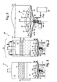
Fig. 1 shows a winemaking apparatus according to the invention; -
Fig. 2 shows a second winemaking apparatus according to the invention; -
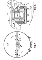
Fig. 3 shows a magnified detail of the winemaking apparatuses inFig. 1 and 2 ; -
Fig. 4 shows an enlarged cross-sectional view along the plane IV-IV offig. 3 ; -
Fig. 4 shows an enlarged detail offig. 3 in vertical cross-section. - The invention can be adapted to many types of winemaking apparatuses.
- For example in
fig. 1 there is shown awinemaking apparatus 10 with anupper tank 12 and alower tank 14. Must M is put to ferment in thetank 12, whereupon its most liquid part will be transferred by gravity (draining) in thetank 14 through a pipe system P1. - In
fig. 2 , instead, there is shown awinemaking apparatus 30 with anupper tank 32 and alower tank 34. Must M is put to ferment in thetank 34, and from fermentation afloating marc cap 36 and a quantity of gas which accumulates in thereservoir 32 are generated. - By operating a pipe and the valve system P2 gases are released under the
cap 36 for crushing it and spraying it with must. - In both cases the must M sediments and gives rise to a layer of dregs on the
tank bottom fig. 3 reference 50, serves to scrape and oxygenate it. Since thedevice 50 may be used indifferently in the twowinemaking apparatuses - The device 50 (
Fig. 4 ) is mounted on thebottom tank blades 56 set in rotation by anexternal motor 60 about a vertical axis X. - On the
wings 56 there are fixed a reinforcement vertical fan-shaped plate 52, parallel to the axis X, and a vertical arc-shaped blade 54 resting on the ends of thewings 56. A void space is thus formed between theblade 54 and the plate 52 (the shape of theblade 54 and theplate 52 may be different from those shown). - The
wings 56 are connected to a rotatable support 58 (Fig. 5 ) which is part of anairtight joint 71 transferring rotary motion from themotor 60 to thewings 56 through agearmotor 73 comprising gears allowing transmission by 90[deg.] and rpm-adaptation of the rotary motion generated by themotor 60 and brought to thewings 56. - The
joint 71 is mounted with afixed collar 80 on thegearmotor 73. Thecollar 80 presents anopening 82 in which apipe 84 is sealingly inserted, whose function is to convey 02 or food air or any other gas from asource 88 to the inside of thetank pipe 84 there is mounted avalve 86 to adjust such a gas flow. - The
collar 80 contains acylindrical block 90 allowing the hermetic fastening to thebottom block 90 has aconduit 92, coaxial to the opening 82, which communicates with aninner seal ring 91. Thering 91 is provided with radial seals in contact to which the stem of thesupport 58 can tightly rotate, driven by a pinion of thegearmotor 73. In thering 91 an internalvertical conduit 94 is made which on one part opens inside the tank just below thewings 56 and on the other communicates with anannular seat 97 of thesame ring 91. Theseat 97 communicates with both the inlet of theconduit 94 and the outlet of theconduit 92, therefore an overall path for the gas between thepipe 84 and the outlet of theconduit 94 is established even when thesupport 58 rotates. - Through the internal construction of the
joint 71 it is thus allowed the injection of 02 into thetank 14, 24 with simultaneous rotation of thenozzles 42. The gas transported by thepipe 84 goes through thejoint 71 and comes out of theconduit 94, where it is able to feed a plurality ofsmall tubes 40 ending withnozzles 42 located on top of the blade 54 (said nozzles and small tubes could also be attached to the scraping blades 56). Thesmall tubes 40 are integral with thesupport 58 and can rotate together with it. The nozzles are oriented towards the center or the top of the tank, properly raised and/or spaced from thebottom tank 14, 24 thanks to theblade 54. Thus, greater is the mass of must M concerned by oxygenation. - The operation of the
device 50 is as follows. - When the
motor 60 sets in rotation thewings 56 and theblade 54, thevalve 86 is set open. Therefore, a combined action of three factors is achieved: thewings 56 scrape the dregs from the bottom of the tank, the blade 54 (and also to a lesser extent the plate 52) mixes them in the must and thenozzles 42 oxygenate the dregs raised in, and, the must itself. - The shape of the
plate 52 and theblade 54 may also be clearly different, depending on the characteristics of the crushed material (a comb- or mashed-blade or by integrating vanes). - A control unit (e.g. a PLC) may control singly the
nozzles 42 , for example their flow rate (through valves on each of them) and/or their spatial orientation, for example through driving of tilt regulators (e.g. linear actuators). This allows establishing an oxygenation program, in which e.g. the flow rate and entry points of 02 vary over time and space.
Claims (10)
- Apparatus (10, 30) for the treatment of a vegetable product in the form of crushed material or liquid, preferentially must, comprising- a tank (14, 34) to contain the vegetable product;- scraping means (56) for scraping the dregs depositing on the bottom (18, 28) of the tank;- one or more nozzles (42) connected to a source of oxygen (88), food air or the like, and adapted to oxygenate the dregs,
wherein one or more nozzles (42) are movably mounted inside the tank and integrated in the scraping means (56), the scraping means comprising one or more scraping members (56) rotatably mounted on and in sliding contact with the bottom (18, 28) of the tank, on said one or more scraping members (56) being integrally arranged said nozzles (42),
characterized by comprising
a gearmotor (73) which is fixed outside the bottom (18, 28) of the tank (14, 24) and has a shaft operatively connected to at least one scraping member (56) to transfer thereto the rotary motion generated by a motor (60), between said shaft and said at least one scraping member (56) being interposed an airtight joint comprising an inlet for feeding with oxygen, food air or the like the one or more nozzles from the outside. - Apparatus according to claim 1, wherein said airtight joint comprises- an external fixed member (80, 90) having an inlet opening (82) for oxygen, food air or the like,- an internal member (58) hermetically and rotatably contained within the external fixed member (80, 90), the internal member (58) having a conduit (94) formed integrally in it and adapted to fluidically communicate with said inlet opening (82) for most of, or all, a round angle, and which opens into the tank.
- Apparatus according to claim 2, wherein the external fixed member (80) contains a cylindrical block (90) allowing the hermetic fastening to the bottom (18, 28) and has a conduit (92), coaxial to said opening (82), which communicates with an inner seal ring (91) provided with radial seals in contact to which the stem of a support (58) for the nozzles can tightly rotate, in said ring (91) an internal vertical conduit 94 being made which on one part opens inside the tank and on the other communicates with an annular seat (97) of the ring (91).
- Apparatus according to claim 3, wherein the seat (97) communicates with both the inlet of the conduit (94) and the outlet of the conduit (92), thereby establishing an overall path for the gas between the pipe (84) and the outlet of the conduit (94) even when the support 58 rotates.
- Apparatus according to any one of the claims 1 to 4, wherein one or more nozzles are arranged on a spacing member (54) extending from a scraping member (56) towards the center and/or the top of the tank, in order to increase the mass of vegetable product involved in the oxygenation.
- Apparatus according to any of the claims 1 to 5, wherein one or more nozzles (42) are arranged on a rotatable support member placed inside the tank at a height greater than the scraping means and rotatable independently therefrom.
- Apparatus according to claim 6, comprising driving means for rotating the rotatable support member with opposite rotation to the scraping means.
- Apparatus according to any of the preceding claims, comprising a second tank superimposed to the first from which the must can drain.
- Apparatus according to any of the preceding claims, comprising means for controlling the flow rate of each nozzle independently from each other.
- Apparatus according to any of the preceding claims, comprising means for controlling the spatial orientation of each nozzle independently from each other.
Priority Applications (1)
| Application Number | Priority Date | Filing Date | Title |
|---|---|---|---|
| EP20080425685 EP2179664B1 (en) | 2008-10-22 | 2008-10-22 | Apparatus for the treatment of a vegetable product |
Applications Claiming Priority (1)
| Application Number | Priority Date | Filing Date | Title |
|---|---|---|---|
| EP20080425685 EP2179664B1 (en) | 2008-10-22 | 2008-10-22 | Apparatus for the treatment of a vegetable product |
Publications (2)
| Publication Number | Publication Date |
|---|---|
| EP2179664A1 EP2179664A1 (en) | 2010-04-28 |
| EP2179664B1 true EP2179664B1 (en) | 2013-09-04 |
Family
ID=40433758
Family Applications (1)
| Application Number | Title | Priority Date | Filing Date |
|---|---|---|---|
| EP20080425685 Not-in-force EP2179664B1 (en) | 2008-10-22 | 2008-10-22 | Apparatus for the treatment of a vegetable product |
Country Status (1)
| Country | Link |
|---|---|
| EP (1) | EP2179664B1 (en) |
Families Citing this family (8)
| Publication number | Priority date | Publication date | Assignee | Title |
|---|---|---|---|---|
| WO2011148227A1 (en) * | 2010-05-25 | 2011-12-01 | Lasi S.R.L. | Improved fermentation apparatus |
| EP2576756A1 (en) | 2010-05-25 | 2013-04-10 | Lasi Srl | Improved fermentation apparatus |
| US9381550B2 (en) * | 2013-05-06 | 2016-07-05 | Spokane Industires | Self-cleaning tank |
| WO2016087966A1 (en) * | 2014-12-02 | 2016-06-09 | Parsec S.R.L. | Method and device for controlled air injection into a vinification tank |
| EP3144377A1 (en) * | 2015-09-17 | 2017-03-22 | Andrea Elegir | Tank for oxygen-free fermentation and method for winemaking |
| ES2747427R1 (en) * | 2018-05-18 | 2020-12-28 | Productos Agrovin S A | PROCEDURE FOR THE RETRIEVAL OF THE HARVEST DURING THE MACERATION AND RETRIEVER OF THE HARVEST |
| ES2714952B2 (en) * | 2018-05-18 | 2020-07-10 | Productos Agrovin S A | PROCEDURE AND EQUIPMENT FOR STORING DURING HARVEST MACERATION |
| ES2715116B2 (en) | 2018-05-18 | 2020-02-05 | Productos Agrovin S A | PROCEDURE FOR DISCOVERY OF THE VINTAGE AND DISCOVERER OF VINTAGE |
Family Cites Families (10)
| Publication number | Priority date | Publication date | Assignee | Title |
|---|---|---|---|---|
| DE10153C (en) | L. BAUMEISTER in Gaggenau | Wine ventilation machine | ||
| US2181839A (en) * | 1938-05-12 | 1939-11-28 | Cornell Res Foundation Inc | Wine process |
| FR2596768A1 (en) * | 1986-08-28 | 1987-10-09 | Magyar Sa | Improvements made to wine-making methods and devices |
| FR2629096B1 (en) * | 1988-03-22 | 1992-01-10 | Air Liquide | METHOD FOR THE CONTROLLED OXYGENATION OF AN ALCOHOLIC FERMENTATION MUST, AND CORRESPONDING INSTALLATION |
| FR2732977B1 (en) * | 1995-04-11 | 1997-05-23 | Schultis Erich | WINEMAKING PROCESS AND DEVICE FOR IMPLEMENTING THE PROCESS |
| IT1311484B1 (en) * | 1999-02-05 | 2002-03-13 | Ifind Srl | CONTAINER AND FERMENTATION APPARATUS OF MUST. |
| IT1319958B1 (en) * | 2000-03-13 | 2003-11-12 | Gimar Tecno S R L | FERMENTATION TANK. |
| ITTO20020706A1 (en) | 2002-08-07 | 2004-02-08 | Gimar Tecno Srl | WINE STORAGE EQUIPMENT. |
| ITMO20030243A1 (en) * | 2003-09-04 | 2005-03-05 | Tecnogen S R L | APPARATUS AND METHOD FOR WORKING VEGETABLE PRODUCTS. |
| DE202005007341U1 (en) * | 2005-05-10 | 2005-09-08 | Tseng, Kuang-Tai, Yonghe | Assembly to accelerate the maturing process of a drink by a sequence of oxidation and exposure to magnetic force |
-
2008
- 2008-10-22 EP EP20080425685 patent/EP2179664B1/en not_active Not-in-force
Also Published As
| Publication number | Publication date |
|---|---|
| EP2179664A1 (en) | 2010-04-28 |
Similar Documents
| Publication | Publication Date | Title |
|---|---|---|
| EP2179664B1 (en) | Apparatus for the treatment of a vegetable product | |
| CN112262802B (en) | Movable quantitative bait feeding and pesticide spraying integrated system and method for aquaculture | |
| TWI444470B (en) | System and apparatus for feeding, solubilizing, growing and discharging a biological material | |
| US4594006A (en) | Apparatus for mixing and pumping slurry | |
| EP0861685B1 (en) | An agitation tank | |
| US5549384A (en) | Mixer with helically extending blades | |
| KR101484663B1 (en) | Apparatus for preventing precipitation of sludge, agitating liquid and micro bubble aerator in liquid storage tank | |
| US20180016756A1 (en) | Method and apparatus for filling potholes with liquid pothole filler | |
| US20210370245A1 (en) | Fluid handling apparatus and fluid tank system | |
| WO2012028291A1 (en) | Apparatus and method for mixing a powder with a liquid | |
| KR101618014B1 (en) | Anaerobic digestion device having inner wall | |
| KR101258691B1 (en) | Apparatus for manufacturing liquid manure close type | |
| CN208372948U (en) | A kind of auger tank | |
| KR20180009734A (en) | Container with stirring device for fluid product | |
| KR20160095489A (en) | Device for reducing weight of organized sludge by fermentation and dry | |
| KR20170000996U (en) | Mixing device for liquid | |
| KR101172036B1 (en) | particle coating apparatus | |
| RU2610674C1 (en) | Bioreactor for biochemical processes | |
| JP6770670B2 (en) | A ventilation stirring type liquid medium fermentation tank equipped with an automatic device for fluid communication between the ascending flow space and the descending flow space according to the height of the liquid medium. | |
| EP2064387B1 (en) | A method and apparatus for filling and cleaning a pulp tower | |
| RU2299903C2 (en) | Bioreactor | |
| KR20090030694A (en) | Mixer for feed | |
| US20210252564A1 (en) | Cleaning Arrangement for a Coating Apparatus | |
| CN208845771U (en) | A kind of pharmaceutical manufacturing preparing tank | |
| US20140367332A1 (en) | Septic system and method of treating sewage and grease |
Legal Events
| Date | Code | Title | Description |
|---|---|---|---|
| PUAI | Public reference made under article 153(3) epc to a published international application that has entered the european phase |
Free format text: ORIGINAL CODE: 0009012 |
|
| AK | Designated contracting states |
Kind code of ref document: A1 Designated state(s): AT BE BG CH CY CZ DE DK EE ES FI FR GB GR HR HU IE IS IT LI LT LU LV MC MT NL NO PL PT RO SE SI SK TR |
|
| AX | Request for extension of the european patent |
Extension state: AL BA MK RS |
|
| 17P | Request for examination filed |
Effective date: 20101008 |
|
| 17Q | First examination report despatched |
Effective date: 20101111 |
|
| AKX | Designation fees paid |
Designated state(s): AT BE BG CH CY CZ DE DK EE ES FI FR GB GR HR HU IE IS IT LI LT LU LV MC MT NL NO PL PT RO SE SI SK TR |
|
| GRAP | Despatch of communication of intention to grant a patent |
Free format text: ORIGINAL CODE: EPIDOSNIGR1 |
|
| INTG | Intention to grant announced |
Effective date: 20130327 |
|
| RIN1 | Information on inventor provided before grant (corrected) |
Inventor name: CROSATO, REMO |
|
| GRAS | Grant fee paid |
Free format text: ORIGINAL CODE: EPIDOSNIGR3 |
|
| GRAA | (expected) grant |
Free format text: ORIGINAL CODE: 0009210 |
|
| RAP1 | Party data changed (applicant data changed or rights of an application transferred) |
Owner name: NOFORM S.R.L. |
|
| AK | Designated contracting states |
Kind code of ref document: B1 Designated state(s): AT BE BG CH CY CZ DE DK EE ES FI FR GB GR HR HU IE IS IT LI LT LU LV MC MT NL NO PL PT RO SE SI SK TR |
|
| REG | Reference to a national code |
Ref country code: GB Ref legal event code: FG4D |
|
| REG | Reference to a national code |
Ref country code: CH Ref legal event code: EP |
|
| REG | Reference to a national code |
Ref country code: AT Ref legal event code: REF Ref document number: 629976 Country of ref document: AT Kind code of ref document: T Effective date: 20130915 |
|
| REG | Reference to a national code |
Ref country code: IE Ref legal event code: FG4D |
|
| REG | Reference to a national code |
Ref country code: DE Ref legal event code: R096 Ref document number: 602008027275 Country of ref document: DE Effective date: 20131031 |
|
| REG | Reference to a national code |
Ref country code: AT Ref legal event code: MK05 Ref document number: 629976 Country of ref document: AT Kind code of ref document: T Effective date: 20130904 |
|
| REG | Reference to a national code |
Ref country code: NL Ref legal event code: VDEP Effective date: 20130904 |
|
| PG25 | Lapsed in a contracting state [announced via postgrant information from national office to epo] |
Ref country code: AT Free format text: LAPSE BECAUSE OF FAILURE TO SUBMIT A TRANSLATION OF THE DESCRIPTION OR TO PAY THE FEE WITHIN THE PRESCRIBED TIME-LIMIT Effective date: 20130904 Ref country code: LT Free format text: LAPSE BECAUSE OF FAILURE TO SUBMIT A TRANSLATION OF THE DESCRIPTION OR TO PAY THE FEE WITHIN THE PRESCRIBED TIME-LIMIT Effective date: 20130904 Ref country code: SE Free format text: LAPSE BECAUSE OF FAILURE TO SUBMIT A TRANSLATION OF THE DESCRIPTION OR TO PAY THE FEE WITHIN THE PRESCRIBED TIME-LIMIT Effective date: 20130904 Ref country code: HR Free format text: LAPSE BECAUSE OF FAILURE TO SUBMIT A TRANSLATION OF THE DESCRIPTION OR TO PAY THE FEE WITHIN THE PRESCRIBED TIME-LIMIT Effective date: 20130904 Ref country code: NO Free format text: LAPSE BECAUSE OF FAILURE TO SUBMIT A TRANSLATION OF THE DESCRIPTION OR TO PAY THE FEE WITHIN THE PRESCRIBED TIME-LIMIT Effective date: 20131204 Ref country code: CY Free format text: LAPSE BECAUSE OF FAILURE TO SUBMIT A TRANSLATION OF THE DESCRIPTION OR TO PAY THE FEE WITHIN THE PRESCRIBED TIME-LIMIT Effective date: 20130828 |
|
| REG | Reference to a national code |
Ref country code: NL Ref legal event code: VDEP Effective date: 20130904 |
|
| REG | Reference to a national code |
Ref country code: LT Ref legal event code: MG4D |
|
| PG25 | Lapsed in a contracting state [announced via postgrant information from national office to epo] |
Ref country code: FI Free format text: LAPSE BECAUSE OF FAILURE TO SUBMIT A TRANSLATION OF THE DESCRIPTION OR TO PAY THE FEE WITHIN THE PRESCRIBED TIME-LIMIT Effective date: 20130904 Ref country code: SI Free format text: LAPSE BECAUSE OF FAILURE TO SUBMIT A TRANSLATION OF THE DESCRIPTION OR TO PAY THE FEE WITHIN THE PRESCRIBED TIME-LIMIT Effective date: 20130904 Ref country code: ES Free format text: LAPSE BECAUSE OF FAILURE TO SUBMIT A TRANSLATION OF THE DESCRIPTION OR TO PAY THE FEE WITHIN THE PRESCRIBED TIME-LIMIT Effective date: 20130904 Ref country code: LV Free format text: LAPSE BECAUSE OF FAILURE TO SUBMIT A TRANSLATION OF THE DESCRIPTION OR TO PAY THE FEE WITHIN THE PRESCRIBED TIME-LIMIT Effective date: 20130904 Ref country code: PL Free format text: LAPSE BECAUSE OF FAILURE TO SUBMIT A TRANSLATION OF THE DESCRIPTION OR TO PAY THE FEE WITHIN THE PRESCRIBED TIME-LIMIT Effective date: 20130904 |
|
| PG25 | Lapsed in a contracting state [announced via postgrant information from national office to epo] |
Ref country code: BE Free format text: LAPSE BECAUSE OF FAILURE TO SUBMIT A TRANSLATION OF THE DESCRIPTION OR TO PAY THE FEE WITHIN THE PRESCRIBED TIME-LIMIT Effective date: 20130904 Ref country code: CY Free format text: LAPSE BECAUSE OF FAILURE TO SUBMIT A TRANSLATION OF THE DESCRIPTION OR TO PAY THE FEE WITHIN THE PRESCRIBED TIME-LIMIT Effective date: 20130904 |
|
| PG25 | Lapsed in a contracting state [announced via postgrant information from national office to epo] |
Ref country code: CZ Free format text: LAPSE BECAUSE OF FAILURE TO SUBMIT A TRANSLATION OF THE DESCRIPTION OR TO PAY THE FEE WITHIN THE PRESCRIBED TIME-LIMIT Effective date: 20130904 Ref country code: IS Free format text: LAPSE BECAUSE OF FAILURE TO SUBMIT A TRANSLATION OF THE DESCRIPTION OR TO PAY THE FEE WITHIN THE PRESCRIBED TIME-LIMIT Effective date: 20140104 Ref country code: EE Free format text: LAPSE BECAUSE OF FAILURE TO SUBMIT A TRANSLATION OF THE DESCRIPTION OR TO PAY THE FEE WITHIN THE PRESCRIBED TIME-LIMIT Effective date: 20130904 Ref country code: SK Free format text: LAPSE BECAUSE OF FAILURE TO SUBMIT A TRANSLATION OF THE DESCRIPTION OR TO PAY THE FEE WITHIN THE PRESCRIBED TIME-LIMIT Effective date: 20130904 Ref country code: RO Free format text: LAPSE BECAUSE OF FAILURE TO SUBMIT A TRANSLATION OF THE DESCRIPTION OR TO PAY THE FEE WITHIN THE PRESCRIBED TIME-LIMIT Effective date: 20130904 Ref country code: NL Free format text: LAPSE BECAUSE OF FAILURE TO SUBMIT A TRANSLATION OF THE DESCRIPTION OR TO PAY THE FEE WITHIN THE PRESCRIBED TIME-LIMIT Effective date: 20130904 |
|
| REG | Reference to a national code |
Ref country code: CH Ref legal event code: PL |
|
| REG | Reference to a national code |
Ref country code: DE Ref legal event code: R097 Ref document number: 602008027275 Country of ref document: DE |
|
| PG25 | Lapsed in a contracting state [announced via postgrant information from national office to epo] |
Ref country code: MC Free format text: LAPSE BECAUSE OF FAILURE TO SUBMIT A TRANSLATION OF THE DESCRIPTION OR TO PAY THE FEE WITHIN THE PRESCRIBED TIME-LIMIT Effective date: 20130904 Ref country code: PT Free format text: LAPSE BECAUSE OF FAILURE TO SUBMIT A TRANSLATION OF THE DESCRIPTION OR TO PAY THE FEE WITHIN THE PRESCRIBED TIME-LIMIT Effective date: 20140106 |
|
| PLBE | No opposition filed within time limit |
Free format text: ORIGINAL CODE: 0009261 |
|
| STAA | Information on the status of an ep patent application or granted ep patent |
Free format text: STATUS: NO OPPOSITION FILED WITHIN TIME LIMIT |
|
| REG | Reference to a national code |
Ref country code: IE Ref legal event code: MM4A |
|
| PG25 | Lapsed in a contracting state [announced via postgrant information from national office to epo] |
Ref country code: LI Free format text: LAPSE BECAUSE OF NON-PAYMENT OF DUE FEES Effective date: 20131031 Ref country code: CH Free format text: LAPSE BECAUSE OF NON-PAYMENT OF DUE FEES Effective date: 20131031 |
|
| 26N | No opposition filed |
Effective date: 20140605 |
|
| GBPC | Gb: european patent ceased through non-payment of renewal fee |
Effective date: 20131204 |
|
| REG | Reference to a national code |
Ref country code: DE Ref legal event code: R097 Ref document number: 602008027275 Country of ref document: DE Effective date: 20140605 |
|
| PG25 | Lapsed in a contracting state [announced via postgrant information from national office to epo] |
Ref country code: DK Free format text: LAPSE BECAUSE OF FAILURE TO SUBMIT A TRANSLATION OF THE DESCRIPTION OR TO PAY THE FEE WITHIN THE PRESCRIBED TIME-LIMIT Effective date: 20130904 |
|
| PG25 | Lapsed in a contracting state [announced via postgrant information from national office to epo] |
Ref country code: IE Free format text: LAPSE BECAUSE OF NON-PAYMENT OF DUE FEES Effective date: 20131022 |
|
| PG25 | Lapsed in a contracting state [announced via postgrant information from national office to epo] |
Ref country code: GB Free format text: LAPSE BECAUSE OF NON-PAYMENT OF DUE FEES Effective date: 20131204 |
|
| PG25 | Lapsed in a contracting state [announced via postgrant information from national office to epo] |
Ref country code: TR Free format text: LAPSE BECAUSE OF FAILURE TO SUBMIT A TRANSLATION OF THE DESCRIPTION OR TO PAY THE FEE WITHIN THE PRESCRIBED TIME-LIMIT Effective date: 20130904 |
|
| PG25 | Lapsed in a contracting state [announced via postgrant information from national office to epo] |
Ref country code: LU Free format text: LAPSE BECAUSE OF NON-PAYMENT OF DUE FEES Effective date: 20131022 Ref country code: BG Free format text: LAPSE BECAUSE OF FAILURE TO SUBMIT A TRANSLATION OF THE DESCRIPTION OR TO PAY THE FEE WITHIN THE PRESCRIBED TIME-LIMIT Effective date: 20130904 Ref country code: HU Free format text: LAPSE BECAUSE OF FAILURE TO SUBMIT A TRANSLATION OF THE DESCRIPTION OR TO PAY THE FEE WITHIN THE PRESCRIBED TIME-LIMIT; INVALID AB INITIO Effective date: 20081022 |
|
| PG25 | Lapsed in a contracting state [announced via postgrant information from national office to epo] |
Ref country code: GR Free format text: LAPSE BECAUSE OF NON-PAYMENT OF DUE FEES Effective date: 20130904 Ref country code: MT Free format text: LAPSE BECAUSE OF FAILURE TO SUBMIT A TRANSLATION OF THE DESCRIPTION OR TO PAY THE FEE WITHIN THE PRESCRIBED TIME-LIMIT Effective date: 20130904 |
|
| REG | Reference to a national code |
Ref country code: FR Ref legal event code: PLFP Year of fee payment: 8 |
|
| PGFP | Annual fee paid to national office [announced via postgrant information from national office to epo] |
Ref country code: DE Payment date: 20151028 Year of fee payment: 8 |
|
| REG | Reference to a national code |
Ref country code: FR Ref legal event code: PLFP Year of fee payment: 9 |
|
| REG | Reference to a national code |
Ref country code: DE Ref legal event code: R119 Ref document number: 602008027275 Country of ref document: DE |
|
| PG25 | Lapsed in a contracting state [announced via postgrant information from national office to epo] |
Ref country code: DE Free format text: LAPSE BECAUSE OF NON-PAYMENT OF DUE FEES Effective date: 20170503 |
|
| REG | Reference to a national code |
Ref country code: FR Ref legal event code: PLFP Year of fee payment: 10 |
|
| REG | Reference to a national code |
Ref country code: FR Ref legal event code: PLFP Year of fee payment: 11 |
|
| PGFP | Annual fee paid to national office [announced via postgrant information from national office to epo] |
Ref country code: FR Payment date: 20191025 Year of fee payment: 12 Ref country code: IT Payment date: 20191014 Year of fee payment: 12 |
|
| PG25 | Lapsed in a contracting state [announced via postgrant information from national office to epo] |
Ref country code: FR Free format text: LAPSE BECAUSE OF NON-PAYMENT OF DUE FEES Effective date: 20201031 |
|
| PG25 | Lapsed in a contracting state [announced via postgrant information from national office to epo] |
Ref country code: IT Free format text: LAPSE BECAUSE OF NON-PAYMENT OF DUE FEES Effective date: 20201022 |
|
| P01 | Opt-out of the competence of the unified patent court (upc) registered |
Effective date: 20230515 |