EP2179644B1 - Dispositif collecteur pour installations de traite - Google Patents
Dispositif collecteur pour installations de traite Download PDFInfo
- Publication number
- EP2179644B1 EP2179644B1 EP08425678A EP08425678A EP2179644B1 EP 2179644 B1 EP2179644 B1 EP 2179644B1 EP 08425678 A EP08425678 A EP 08425678A EP 08425678 A EP08425678 A EP 08425678A EP 2179644 B1 EP2179644 B1 EP 2179644B1
- Authority
- EP
- European Patent Office
- Prior art keywords
- milk
- cup
- cover
- manifold
- nipples
- Prior art date
- Legal status (The legal status is an assumption and is not a legal conclusion. Google has not performed a legal analysis and makes no representation as to the accuracy of the status listed.)
- Active
Links
- 210000004080 milk Anatomy 0.000 claims description 80
- 239000008267 milk Substances 0.000 claims description 80
- 235000013336 milk Nutrition 0.000 claims description 78
- 210000002445 nipple Anatomy 0.000 claims description 65
- 230000010349 pulsation Effects 0.000 claims description 24
- 230000008878 coupling Effects 0.000 claims description 10
- 238000010168 coupling process Methods 0.000 claims description 10
- 238000005859 coupling reaction Methods 0.000 claims description 10
- 230000035939 shock Effects 0.000 claims description 7
- 238000004140 cleaning Methods 0.000 claims description 5
- 210000004072 lung Anatomy 0.000 claims description 3
- 239000012858 resilient material Substances 0.000 claims description 2
- 230000002452 interceptive effect Effects 0.000 claims 1
- 241000283690 Bos taurus Species 0.000 description 19
- 241001465754 Metazoa Species 0.000 description 13
- 241000894006 Bacteria Species 0.000 description 5
- 239000012530 fluid Substances 0.000 description 5
- 230000000717 retained effect Effects 0.000 description 4
- 229910001220 stainless steel Inorganic materials 0.000 description 4
- 239000010935 stainless steel Substances 0.000 description 4
- 210000000078 claw Anatomy 0.000 description 3
- 230000000694 effects Effects 0.000 description 3
- 239000011796 hollow space material Substances 0.000 description 3
- 208000015181 infectious disease Diseases 0.000 description 3
- 239000000463 material Substances 0.000 description 3
- 239000012815 thermoplastic material Substances 0.000 description 3
- 238000009825 accumulation Methods 0.000 description 2
- 230000009471 action Effects 0.000 description 2
- 210000001789 adipocyte Anatomy 0.000 description 2
- 244000309466 calf Species 0.000 description 2
- 238000004891 communication Methods 0.000 description 2
- 238000006073 displacement reaction Methods 0.000 description 2
- 239000006260 foam Substances 0.000 description 2
- 230000036541 health Effects 0.000 description 2
- 230000001473 noxious effect Effects 0.000 description 2
- 229920003023 plastic Polymers 0.000 description 2
- 238000007789 sealing Methods 0.000 description 2
- 210000005070 sphincter Anatomy 0.000 description 2
- 206010061218 Inflammation Diseases 0.000 description 1
- 230000001580 bacterial effect Effects 0.000 description 1
- 230000006399 behavior Effects 0.000 description 1
- 210000000481 breast Anatomy 0.000 description 1
- 210000004027 cell Anatomy 0.000 description 1
- 238000004040 coloring Methods 0.000 description 1
- 230000006835 compression Effects 0.000 description 1
- 238000007906 compression Methods 0.000 description 1
- 238000011109 contamination Methods 0.000 description 1
- 230000010485 coping Effects 0.000 description 1
- 230000003247 decreasing effect Effects 0.000 description 1
- 230000007850 degeneration Effects 0.000 description 1
- 238000000605 extraction Methods 0.000 description 1
- 239000012535 impurity Substances 0.000 description 1
- 230000004054 inflammatory process Effects 0.000 description 1
- 238000004519 manufacturing process Methods 0.000 description 1
- 208000004396 mastitis Diseases 0.000 description 1
- 239000002184 metal Substances 0.000 description 1
- 238000000034 method Methods 0.000 description 1
- 230000000149 penetrating effect Effects 0.000 description 1
- 239000004033 plastic Substances 0.000 description 1
- 230000000644 propagated effect Effects 0.000 description 1
- 230000002040 relaxant effect Effects 0.000 description 1
- 239000011347 resin Substances 0.000 description 1
- 229920005989 resin Polymers 0.000 description 1
- 239000000126 substance Substances 0.000 description 1
- 239000010409 thin film Substances 0.000 description 1
- 230000009466 transformation Effects 0.000 description 1
- 238000005406 washing Methods 0.000 description 1
Images


Classifications
-
- A—HUMAN NECESSITIES
- A01—AGRICULTURE; FORESTRY; ANIMAL HUSBANDRY; HUNTING; TRAPPING; FISHING
- A01J—MANUFACTURE OF DAIRY PRODUCTS
- A01J5/00—Milking machines or devices
- A01J5/04—Milking machines or devices with pneumatic manipulation of teats
- A01J5/041—Milk claw
Definitions
- DE 10132132 (A1 ) discloses a manifold device for milking plants comprising two hollow portions coupled with each other and a deflector member located inside the volume enclosed between said hollow portions and defined by rectangular vertical radial screens, wherein said deflector is supported within said volume by retaining means provided on the inner surface of said hollow portions which cooperate with said radial screens.
- the prior art manifold devices generally are not built so as to adapt themselves to the different types and ages of the animal.
- the four teats of a cow are configured in regular manner only in young animals, whereas, as years go by and the number of calves suckled by a same animal increases, the divergence of one teat pair with respect to the other increases more and more.
- the phenomenon is due to the suction from a preferential and more easily accessible teat pair by a calf in order to be able to feed itself
- the manifold devices are to be made of a robust material, since they can undergo shocks and can be trampled on by the animals. Notwithstanding this, breakages frequently occur because of the heavy duty the manifold devices are subjected to.
- the invention aims at providing a manifold device that can be implemented in cheap manner and can be manufactured on industrial scale with reduced costs.
- the manifold device according to the invention essentially consists of two portions coupled to each other e.g. by means of a bayonet coupling, with a vacuum-tight gasket interposed therebetween.
- the manifold device according to the invention internally has a deflector member acting so that milk flows according to an almost laminar motion.
- the manifold device according to the invention advantageously has a racy shape, without rough areas, in the parts licked by milk and thus it allows keeping a fluido-dynamic behaviour of the flowing milk which is close to the laminar flow.
- the qualities of the milk that has been milked are maintained even with a high flow speed, thanks to the advantageous internal shape of the manifold device and the presence of the deflector member.
- the pulsation cross has a variable attitude that avoids tensile and torsional stresses onto the ducts applied thereto and gives a greater versatility to the device.
- the manifold device according to the invention can therefore be easily washed both externally and internally and allows therefore maintaining good hygienical conditions of the plant.
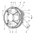
- the first portion 13 of manifold device 11 comprises a cover 21, which is equipped with four nipples 23a, 23b, 23c, 23d for milk inflow and has associated therewith a locking bracket 25 and a distributing member 27, referred to in the art as pulsation cross.
- the second portion 15 of the device or lower portion always according to the orientation of Figs. 1 and 2 , comprises a small cup 29, sealing gasket 19 and preferably an external shock-absorbing ring 31, acting as a protection against side shocks.
- Cover 21 has, besides nipples 23a, 23b, 23c, 23d, a gauged vent hole 37, enabling introduction of a controlled amount of atmospheric air into volume 33 enclosed within manifold device 11, in order to enable a quick discharge of milk. Indeed, it is clear that the motor fluid pushing the transiting milk is represented by such an amount of atmospheric air entering from the outside.
- the wall thickness in portion 41 of cover 21 where hole 37 is formed is approximately half the thickness in the remaining cover portion, so that the hole is made substantially self-cleaning thanks to the reduced friction as air passes through it.
- Cover 21 preferably has circular shape and has a threaded, preferably blind cylindrical central insert 43, which is secured, for instance welded, to cover 21. Said insert 43 is to receive a screw 47 intended to secure locking bracket 25, as it will be better described hereinafter.
- Cover 21 can preferably be made of stainless steel, in a wide range of models differing from one another both in respect of the diameters of nipples 23a, 23b, 23c, 23d (typically in the range from about 10 to 15 mm) and in their inclinations (about 30* to 50°), as well as in the shapes of the free ends thereof, with a perpendicular or an inclined cut.
- a common feature of all models of manifold device 11 consists of the different inclinations of the nipple axes in the nipple pairs provided on cover 21.
- a first nipple pair 23a, 23b, or front pair actually is more closed than the second pair 23c, 23d, or rear pair, which therefore is more divergent: that is, distance "cd” between the centres of the nipple ends in the latter pair is greater than distance "ab” between the centres in the first pair.
- deflector 35 located inside volume 33 is ring shaped and has a substantially frusto-conical central portion 49 intended to intercept and deflect the milk flows entering manifold device 11 and coming from the four nipples 23a, 23b, 23c, 23d.
- Said portion 49 has associated therewith substantially triangular radial screens 51, in the illustrated example four screens mutually spaced by 90°, intended to support the deflector with respect to cup 29 and to divide the milk flow passing through volume 33.
- the shape of deflector member 35 is defined in the whole so that milk flowing in vertical direction, i.e. from top to bottom in Fig. 2 in the direction of arrow F, is directed along internal walls 53 of cup 29 and flows towards cup bottom 55 according to a substantially laminar flow condition.
- the deflection of the milk jets entering manifold 11 along walls 53 of cup 29 caused by deflector member 35 eliminates the risk that milk coming from a nipple goes back up towards the diametrically opposed nipple. Such a phenomenon, if present, would result in the risk of transmitting infections from one teat to another, and advantageously it is avoided thanks to the provision of deflector 35 shaped as described above.
- a laminar milk flow along walls 53 of cup 29 further provides manifold device 11 with a greater stability of the vacuum degree inside it, and this allows achieving a more regular milking, without affecting the health of the animals.
- This result is possible in that, inside manifold 11 according to the invention, a central region is created, substantially corresponding to the internal volume of frusto-conical portion 49 of the deflector member, where milk does not pass. That central region acts as a lung forming a vacuum reserve, indispensable for coping with demand peaks occurring in correspondence with peaks in the flow rate of inflowing milked milk.
- a reserve allows at the same time maintaining a quick milk discharge, even at high flow rates, thereby contributing to speeding up the milking operations even in the heaviest conditions.
- cup 29 which is preferably made of plastic material, which is transparent in order to allow observing the passage of milked milk inside the cup and is suitable for contact with foodstuff, is equipped in the lower portion with a supporting pad 59 of resilient material, partly received in a corresponding hollow provided in cup 29.
- Said supporting pad 59 allows maintaining an optimum attitude of manifold device 11 during milking, in case the manifold arrives in contact with the ground trampled on by the cow, by preventing the manifold from laterally tilting.
- Cup 29 is equipped, at its circular end, with four wedge-shaped teeth 61 radially projecting outwards and allowing the cup to be coupled, through bayonet coupling 17, into respective seats provided in cover 21.
- cup 29 is internally equipped with coplanar radial projections 63, in the illustrated example four projections mutually spaced by 90°, intended to retain the outermost ends of screens 51.
- cup 29 has a substantially hemispherical shape, resulting in an optimum resistance to shocks and crushing, due for instance to the fortuitous trampling on by the animals.
- exhaust 57 is advantageously associated substantially with the centre of bottom 55 of cup 29. Such an arrangement contributes to maximising the milk discharge speed in all working attitudes of the manifold device, and it does not cause internal milk staunching when milking has ended.
- Said exhaust 57 further includes a radially directed duct 65 extending over a length substantially comprised within the overall lateral size of manifold device 11. Thanks to this arrangement, said milk discharge duct 65 is protected from shocks.
- the same duct 65 further internally includes a set of parallel axial fins 67. This arrangement contributes to impart an oriented laminar motion to the milk flow leaving device 11 through duct 65, which motion increases the milk speed and hence improves the draining and the performance of the manifold device.
- cup 29 is moreover externally equipped with side wings 68, in the illustrated example two diametrically opposed wings, which make manual grip easier and therefore make the cup more ergonomic.
- cup 29 can be equipped with a closure valve, internally located in the central portion, in correspondence with exhaust 57.
- cup 29 further has an annular seat 69 intended to house shock-absorbing ring 31, if any.
- Said shock-absorbing ring has the important function of preventing the manifold device from being damaged because of the unavoidable fortuitous shocks occurring during automatic detachment of the milking assembly.
- said shock-absorbing ring 31 interferes with bottom edge 70 of cover 21 it is brought in contact with when bayonet coupling 17 is being locked: This feature prevents dirt from penetrating into the interstices existing between portions 13, 15 of the device, which interstices are practically impossible to clean without disassembling manifold device 11.
- Said shock-absorbing ring 31 is preferably made of rubber or a thermoplastic material with a suitable hardness and geometry.
- sealing gasket 19 is arranged between portions 13, 15 of the device and is received in a suitable circular seat 71 formed in the upper part of cup 29, said gasket having the important task of ensuring vacuum tightness between cover 21 and cup 29.
- the gasket Since the internal portion of gasket 19 is licked by transiting milk, the gasket should be made of a foodstuff-compatible material, for instance thermoplastic material suitable for contact with foodstuff, having characteristics of high stability with time without release of colouring substances.
- the substantially rectangular elongated cross-sectional shape of gasket 19 is such that it ensures, besides vacuum tightness, also that no radial milk leak towards the outside occurs.
- bracket 25 is essential in order to obtain a balanced horizontal attitude of the whole milking assembly and to impart a high resistance to the stresses the whole device is subjected to in use. For this reason, bracket 25 has a substantially U-shaped central portion 73, which has associated therewith an upward directed front portion 75 and a horizontally directed rear appendage 77.
- Locking bracket 25 allows securing manifold device 11, by means of a snap-hook (not shown) inserted into an annular through opening formed at forward end 75 of the bracket, to a rope of a cylinder for the automatic detachment (not shown), of a kind known in the art and used for automatically detaching the milking assembly.
- Rear appendage 77 of locking bracket 25 has a trapezoidal through opening 81 and allows supporting the whole milking assembly turned downwards, i.e. turned upside down with respect to the arrangement shown in Fig. 2 , through a coupling with a suitable male bracket (not shown) of stainless steel, in turn firmly secured for instance to a wall or to the structure of the milking plant.
- This arrangement is essential in that cleaning of the system can be optimally performed when milking has ended.
- Said bracket 25 further includes a pair of half-circular relief portions 83 in the preferably oblique, upward-directed intermediate section 85 of U-shaped portion 73, said relief portions being intended to improve the manual grip should manifold device 11 be manually used.
- Bracket 25 further has a bottom base section 87 with a central hole 89 through which blind threaded central insert 43, secured to cover 21, passes, and two side holes 91 each intended to receive a centring pin 45 provided on and secured to cover 21.
- bracket 25 is made of stainless steel.
- pulsation cross 27 has the essential function of taking the pulsation signal generated by the pulsator, by means of a suitable twin connecting tube, and of distributing such signal alternately to both barrel pairs, with respective sheaths, being part of the milking assembly.
- the presence of vacuum alternating with atmospheric air inside the barrels imparts a cyclical movement of opening and closure on themselves to the sheaths, which movement causes milk extraction from the cow's teats.
- the pair of front nipples 93 in pulsation cross 27 is somewhat inclined downwards, i.e. towards cover 21 of manifold device 11: in this manner, they prevent the twin tube intended to be associated with said front nipples 93 from undergoing the typical, and often marked, S-shaped deviation at its end section close to the coupling with said nipples, since such tube is generally associated through resilient clamps with the underlying milk discharge tube.
- a vertical throughhole 95 is provided centrally of pulsation cross 27 and it allows housing with a certain clearance screw 41 fastening bracket 25 onto cover 21.
- Such a coupling which is partly free since it is vertically slidable along the screw, allows a vertical displacement of pulsation cross 27 relative to cover 21, in the illustrated example a displacement of about 25 mm, as well as a certain rotation of the cross.
- a variable attitude arrangement of the pulsation cross during milking there is obtained an optimum attitude of the pulsation tubes associated with side nipples 97 of the pulsation cross and transmitting the pulsation signal to the barrels in the milking assembly.
- the risk is reduced of generating tensile stresses onto the side pulsation tubes associated with nipples 97 because of particular positions the collecting device may take during milking, which stresses result in the risk that the sheath slides off the animal's teat.
- Said hole 95 is internally provided with parallel axial ribs 96, in the illustrated example three ribs spaced apart by 120°, intended to reduce the contact friction and hence to improve sliding of cross 27 along screw 47.
- each inclined front nipple 93 distributes successively and alternately the pulsation signal to each side nipple pair 97.
- a second model, or “front rear” model differs both geometrically and functionally from the first one in that the two inclined front nipples distribute the pulsation signal, always alternately, to the front and the rear nipples, respectively, in both side nipple pairs.
Claims (15)
- Dispositif collecteur (11) destiné à des installations de traite, comportant :- deux parties creuses (13, 15) couplées l'une avec l'autre, une première partie étant dotée de manchons (23a, 23b, 23c, 23d) permettant au lait de s'écouler dans le dispositif, et une seconde partie étant dotée d'un conduit d'évacuation permettant au lait d'être évacué à partir du dispositif,- un élément déflecteur situé à l'intérieur du volume délimité entre lesdites parties creuses, ledit élément déflecteur contribuant à maintenir un écoulement laminaire du lait passant à travers ledit volume, caractérisé en ce que :- l'élément déflecteur (35) est configuré en forme de bague et présente une portion centrale tronconique (49) conçue pour intercepter et dévier les écoulements de lait entrant dans le dispositif et venant des manchons d'entrée, ladite portion tronconique (49) présentant sa petite base orientée vers le conduit d'évacuation,- à l'intérieur du dispositif collecteur (11), se trouve définie une zone centrale, correspondant essentiellement au volume interne de la portion tronconique (49), ladite zone centrale agissant comme un poumon constituant une réserve de vide où le lait ne passe pas,- ladite portion tronconique (49) présente, associés à elle, des cloisons radiales essentiellement triangulaires (51) conçues pour supporter le déflecteur à l'intérieur du dispositif et pour diviser l'écoulement de lait passant à travers le dispositif,- ladite seconde partie comporte une coupe essentiellement hémisphérique (29) équipée à l'intérieur avec des parties radiales coplanaires en saillie (63) agencées pour retenir les extrémités les plus à l'extérieur des cloisons (51) de l'élément déflecteur.
- Dispositif selon la revendication 1, dans lequel lesdites cloisons radiales (51) et lesdites parties radiales en saillie (63) comptent quatre cloisons et quatre parties en saillie distantes mutuellement de 90°, respectivement.
- Dispositif selon la revendication 1 ou 2, dans lequel la coupe (29) est pourvue, à l'extérieur, d'ailerons latéraux (68), qui rendent plus facile une saisie manuelle et, en conséquence, rendent la coupe plus ergonomique.
- Dispositif selon la revendication 1 ou 2 ou 3, dans lequel la coupe (29) est dotée d'une vanne de fermeture, placée à l'intérieur dans la partie centrale, en correspondance avec l'évacuation (57).
- Dispositif selon l'une quelconque des revendications précédentes, dans lequel ladite première partie comprend un couvercle (21) doté de quatre manchons permettant l'entrée du lait et dans lequel une première paire de manchons (23a, 23b) est moins divergente que la seconde paire de manchons (23c, 23d).
- Dispositif selon la revendication 5, dans lequel le couvercle (21) est pourvu d'un trou de ventilation calibré (37), l'épaisseur de paroi dans la partie de couvercle (41) dans laquelle ledit trou de ventilation (37) est formé représentant la moitié environ de l'épaisseur de la partie de couvercle restante, de sorte que le trou est réalisé de façon essentiellement autonettoyante grâce à la friction réduite lorsque l'air le traverse.
- Dispositif selon la revendication 1, dans lequel la coupe (29) comporte une bague extérieure d'absorption de chocs (31) ayant pour fonction de protéger le dispositif contre les chocs, et dans lequel ladite coupe est dotée, à l'extérieur, au niveau de sa partie inférieure d'un patin de support (59) constitué d'un matériau élastique.
- Dispositif selon la revendication 7, dans lequel la coupe (29) comporte, de plus, une embase annulaire (69) conçue pour loger la bague d'absorption de chocs (31), ladite bague d'absorption de chocs (31) interférant avec le bord inférieur (70) du couvercle (21) avec lequel il est mis en contact lorsque le dispositif collecteur est fermé.
- Dispositif selon la revendication 8, dans lequel l'évacuation (57) est, de façon avantageuse, associée essentiellement avec le centre de la partie inférieure de la coupe (29), et dans lequel ladite évacuation (57) comporte, de plus, un conduit orienté de façon radiale (65) s'étendant sur une longueur comprise essentiellement dans les limites de la dimension latérale globale du dispositif collecteur.
- Dispositif selon la revendication 9, dans lequel ledit conduit (65) comporte, de plus, situé en lui, un ensemble d'ailettes axiales parallèles (67).
- Dispositif selon l'une quelconque des revendications précédentes, comportant un support de verrouillage (25) associé au dit couvercle, ledit support ayant une partie centrale essentiellement configurée en U (73) qui comporte, associée à lui, une partie avant dirigée vers le haut (75) et un appendice arrière dirigé horizontalement (77), et dans lequel l'appendice arrière (77) du support de verrouillage (25) comporte une ouverture de passage (81) et une paire de parties demi circulaires en relief (83) dans la section intermédiaire (85) de la partie configurée en U (73).
- Dispositif selon la revendication 11, dans lequel le support (25) comporte, de plus, une section de base (87) dotée d'un trou central (89) à travers lequel passe une pièce centrale d'insertion filetée (43), fixée au couvercle (21), et deux trous latéraux (91) conçus pour recevoir chacun une broche de centrage (45) prévue sur le, et fixée au, couvercle (21).
- Dispositif selon la revendication 11 ou 12, dans lequel une pièce en croix du pulsateur (27) est prévue comportant une paire de manchons avant (93) et deux paires de manchons latéraux (97), les manchons de la paire de manchons avant étant inclinés vers le couvercle (21) du dispositif collecteur (11), et dans lequel un trou (95) est prévu au centre de la pièce en croix du pulsateur (27) pour recevoir, avec un certain jeu, une vis (47) fixant le support (25) sur le couvercle (21), de telle manière que ladite pièce en croix peut, en partie, tourner librement et coulisser par rapport à la vis et, de ce fait, par rapport au couvercle.
- Dispositif selon l'une quelconque des revendications précédentes, dans lequel le couplage entre les deux dites parties comporte un couplage à baïonnette (17) et dans lequel un joint d'étanchéité étanche au vide (19) est prévu entre les deux parties (13, 15) du dispositif et est reçu dans une embase circulaire (71) prévue dans la coupe (29).
- Dispositif selon la revendication 13, dans lequel ledit trou (95) prévu au centre de la pièce en croix du pulsateur est doté, en interne, de nervures axiales parallèles (96) conçues pour réduire la friction de contact et ainsi, améliorer le coulissement de la pièce en croix (27) le long de la vis (47).
Priority Applications (1)
| Application Number | Priority Date | Filing Date | Title |
|---|---|---|---|
| EP08425678A EP2179644B1 (fr) | 2008-10-21 | 2008-10-21 | Dispositif collecteur pour installations de traite |
Applications Claiming Priority (1)
| Application Number | Priority Date | Filing Date | Title |
|---|---|---|---|
| EP08425678A EP2179644B1 (fr) | 2008-10-21 | 2008-10-21 | Dispositif collecteur pour installations de traite |
Publications (2)
| Publication Number | Publication Date |
|---|---|
| EP2179644A1 EP2179644A1 (fr) | 2010-04-28 |
| EP2179644B1 true EP2179644B1 (fr) | 2011-06-29 |
Family
ID=40521820
Family Applications (1)
| Application Number | Title | Priority Date | Filing Date |
|---|---|---|---|
| EP08425678A Active EP2179644B1 (fr) | 2008-10-21 | 2008-10-21 | Dispositif collecteur pour installations de traite |
Country Status (1)
| Country | Link |
|---|---|
| EP (1) | EP2179644B1 (fr) |
Families Citing this family (2)
| Publication number | Priority date | Publication date | Assignee | Title |
|---|---|---|---|---|
| CN104869813B (zh) | 2012-12-19 | 2018-04-17 | 利拉伐控股有限公司 | 用于挤奶机的集乳器 |
| US10278359B2 (en) * | 2014-09-24 | 2019-05-07 | Interpuls S.P.A. | Double chamber volumetric milk meter |
Citations (2)
| Publication number | Priority date | Publication date | Assignee | Title |
|---|---|---|---|---|
| GB1160900A (en) * | 1966-09-13 | 1969-08-06 | Gascoignes Res & Dev Ltd | Improvements in or relating to Teat Cups for Milking Equipment |
| DE10132132A1 (de) * | 2001-07-03 | 2003-01-16 | Jun Jakob Maier | Milchsammeleinheit |
Family Cites Families (9)
| Publication number | Priority date | Publication date | Assignee | Title |
|---|---|---|---|---|
| GB114033A (en) * | 1917-03-16 | 1918-03-18 | Robert Wallace | Improvements in and relating to Pulsating Apparatus for Milking Machines. |
| US4537152A (en) * | 1984-06-01 | 1985-08-27 | Dec International, Inc. | Milking claw |
| US4936254A (en) * | 1986-05-10 | 1990-06-26 | Ambic Equipment Limited | Automatic milking apparatus |
| US4807566A (en) | 1987-10-05 | 1989-02-28 | Alfa-Laval, Inc. | Milk claw |
| US6439157B1 (en) * | 1997-05-12 | 2002-08-27 | Delaval Holding Ab | Device arranged to permit an air flow from an environment to an inner space |
| NZ528893A (en) | 2003-10-13 | 2005-06-24 | Eliminator Holdings Ltd | An improved fluid treatment system |
| DE102005015916A1 (de) | 2005-04-06 | 2006-10-12 | Fritz Happel | Sammelstück mit Milchleitflächen |
| DE102005017094A1 (de) | 2005-04-13 | 2006-10-19 | Werner Happel | Milchsammelstück |
| US20070272160A1 (en) * | 2006-05-10 | 2007-11-29 | Michael Berentzen | Modified milk-collecting component |
-
2008
- 2008-10-21 EP EP08425678A patent/EP2179644B1/fr active Active
Patent Citations (2)
| Publication number | Priority date | Publication date | Assignee | Title |
|---|---|---|---|---|
| GB1160900A (en) * | 1966-09-13 | 1969-08-06 | Gascoignes Res & Dev Ltd | Improvements in or relating to Teat Cups for Milking Equipment |
| DE10132132A1 (de) * | 2001-07-03 | 2003-01-16 | Jun Jakob Maier | Milchsammeleinheit |
Also Published As
| Publication number | Publication date |
|---|---|
| EP2179644A1 (fr) | 2010-04-28 |
Similar Documents
| Publication | Publication Date | Title |
|---|---|---|
| RU2465768C2 (ru) | Коллектор доильного аппарата с запираемыми камерами | |
| WO2004030445A3 (fr) | Tuyau court a lait | |
| RU2655834C2 (ru) | Молочный патрубок и молокосборный элемент | |
| WO2015150807A1 (fr) | Pot de griffe à lait pour faisceau trayeur | |
| US20070272160A1 (en) | Modified milk-collecting component | |
| WO2006031164A1 (fr) | Gobelet trayeur et piece de gobelet trayeur | |
| EP2179644B1 (fr) | Dispositif collecteur pour installations de traite | |
| US10548291B2 (en) | Teatcup | |
| US1259309A (en) | Milking-machine. | |
| US7617796B2 (en) | Milking claw | |
| AU2003215103B2 (en) | Side outlet milking claw | |
| US20150320005A1 (en) | A claw for a milking machine | |
| Jones | The role of milking equipment in mastitis | |
| US6401655B1 (en) | Milking claw with concave window | |
| US20010054392A1 (en) | Implement for milking animals | |
| US20140209030A1 (en) | High Capacity Milking Claw | |
| RU2323568C1 (ru) | Коллектор доильного аппарата | |
| US3302614A (en) | Milking machine | |
| WO2005107440A1 (fr) | Collecteur pour l'ecoulement de lait | |
| EP2057895B1 (fr) | Soupape automatique pour des installations de traite | |
| RU2150191C1 (ru) | Доильный аппарат для высокопродуктивных коров | |
| GB2564180A (en) | Improvements relating to sampling apparatus | |
| RU124113U1 (ru) | Подвесная часть доильного аппарата для коз | |
| UA28966U (en) | Collector of milking unit | |
| RU2259710C2 (ru) | Доильный аппарат |
Legal Events
| Date | Code | Title | Description |
|---|---|---|---|
| PUAI | Public reference made under article 153(3) epc to a published international application that has entered the european phase |
Free format text: ORIGINAL CODE: 0009012 |
|
| 17P | Request for examination filed |
Effective date: 20091231 |
|
| AK | Designated contracting states |
Kind code of ref document: A1 Designated state(s): AT BE BG CH CY CZ DE DK EE ES FI FR GB GR HR HU IE IS IT LI LT LU LV MC MT NL NO PL PT RO SE SI SK TR |
|
| AX | Request for extension of the european patent |
Extension state: AL BA MK RS |
|
| 17Q | First examination report despatched |
Effective date: 20100504 |
|
| GRAP | Despatch of communication of intention to grant a patent |
Free format text: ORIGINAL CODE: EPIDOSNIGR1 |
|
| AKX | Designation fees paid |
Designated state(s): DE ES GB IT |
|
| GRAS | Grant fee paid |
Free format text: ORIGINAL CODE: EPIDOSNIGR3 |
|
| GRAA | (expected) grant |
Free format text: ORIGINAL CODE: 0009210 |
|
| AK | Designated contracting states |
Kind code of ref document: B1 Designated state(s): DE ES GB IT |
|
| REG | Reference to a national code |
Ref country code: GB Ref legal event code: FG4D |
|
| REG | Reference to a national code |
Ref country code: DE Ref legal event code: R096 Ref document number: 602008007932 Country of ref document: DE Effective date: 20110818 |
|
| PLBE | No opposition filed within time limit |
Free format text: ORIGINAL CODE: 0009261 |
|
| STAA | Information on the status of an ep patent application or granted ep patent |
Free format text: STATUS: NO OPPOSITION FILED WITHIN TIME LIMIT |
|
| 26N | No opposition filed |
Effective date: 20120330 |
|
| REG | Reference to a national code |
Ref country code: DE Ref legal event code: R097 Ref document number: 602008007932 Country of ref document: DE Effective date: 20120330 |
|
| PG25 | Lapsed in a contracting state [announced via postgrant information from national office to epo] |
Ref country code: ES Free format text: LAPSE BECAUSE OF FAILURE TO SUBMIT A TRANSLATION OF THE DESCRIPTION OR TO PAY THE FEE WITHIN THE PRESCRIBED TIME-LIMIT Effective date: 20111010 |
|
| PGFP | Annual fee paid to national office [announced via postgrant information from national office to epo] |
Ref country code: GB Payment date: 20231031 Year of fee payment: 16 |
|
| PGFP | Annual fee paid to national office [announced via postgrant information from national office to epo] |
Ref country code: IT Payment date: 20231024 Year of fee payment: 16 Ref country code: DE Payment date: 20231018 Year of fee payment: 16 |