EP2179644B1 - Manifold device for milking plants - Google Patents
Manifold device for milking plants Download PDFInfo
- Publication number
- EP2179644B1 EP2179644B1 EP08425678A EP08425678A EP2179644B1 EP 2179644 B1 EP2179644 B1 EP 2179644B1 EP 08425678 A EP08425678 A EP 08425678A EP 08425678 A EP08425678 A EP 08425678A EP 2179644 B1 EP2179644 B1 EP 2179644B1
- Authority
- EP
- European Patent Office
- Prior art keywords
- milk
- cup
- cover
- manifold
- nipples
- Prior art date
- Legal status (The legal status is an assumption and is not a legal conclusion. Google has not performed a legal analysis and makes no representation as to the accuracy of the status listed.)
- Ceased
Links
Images




Classifications
-
- A—HUMAN NECESSITIES
- A01—AGRICULTURE; FORESTRY; ANIMAL HUSBANDRY; HUNTING; TRAPPING; FISHING
- A01J—MANUFACTURE OF DAIRY PRODUCTS
- A01J5/00—Milking machines or devices
- A01J5/04—Milking machines or devices with pneumatic manipulation of teats
- A01J5/041—Milk claw
Definitions
- DE 10132132 (A1 ) discloses a manifold device for milking plants comprising two hollow portions coupled with each other and a deflector member located inside the volume enclosed between said hollow portions and defined by rectangular vertical radial screens, wherein said deflector is supported within said volume by retaining means provided on the inner surface of said hollow portions which cooperate with said radial screens.
- the prior art manifold devices generally are not built so as to adapt themselves to the different types and ages of the animal.
- the four teats of a cow are configured in regular manner only in young animals, whereas, as years go by and the number of calves suckled by a same animal increases, the divergence of one teat pair with respect to the other increases more and more.
- the phenomenon is due to the suction from a preferential and more easily accessible teat pair by a calf in order to be able to feed itself
- the manifold devices are to be made of a robust material, since they can undergo shocks and can be trampled on by the animals. Notwithstanding this, breakages frequently occur because of the heavy duty the manifold devices are subjected to.
- the invention aims at providing a manifold device that can be implemented in cheap manner and can be manufactured on industrial scale with reduced costs.
- the manifold device according to the invention essentially consists of two portions coupled to each other e.g. by means of a bayonet coupling, with a vacuum-tight gasket interposed therebetween.
- the manifold device according to the invention internally has a deflector member acting so that milk flows according to an almost laminar motion.
- the manifold device according to the invention advantageously has a racy shape, without rough areas, in the parts licked by milk and thus it allows keeping a fluido-dynamic behaviour of the flowing milk which is close to the laminar flow.
- the qualities of the milk that has been milked are maintained even with a high flow speed, thanks to the advantageous internal shape of the manifold device and the presence of the deflector member.
- the pulsation cross has a variable attitude that avoids tensile and torsional stresses onto the ducts applied thereto and gives a greater versatility to the device.
- the manifold device according to the invention can therefore be easily washed both externally and internally and allows therefore maintaining good hygienical conditions of the plant.
- the first portion 13 of manifold device 11 comprises a cover 21, which is equipped with four nipples 23a, 23b, 23c, 23d for milk inflow and has associated therewith a locking bracket 25 and a distributing member 27, referred to in the art as pulsation cross.
- the second portion 15 of the device or lower portion always according to the orientation of Figs. 1 and 2 , comprises a small cup 29, sealing gasket 19 and preferably an external shock-absorbing ring 31, acting as a protection against side shocks.
- Cover 21 has, besides nipples 23a, 23b, 23c, 23d, a gauged vent hole 37, enabling introduction of a controlled amount of atmospheric air into volume 33 enclosed within manifold device 11, in order to enable a quick discharge of milk. Indeed, it is clear that the motor fluid pushing the transiting milk is represented by such an amount of atmospheric air entering from the outside.
- the wall thickness in portion 41 of cover 21 where hole 37 is formed is approximately half the thickness in the remaining cover portion, so that the hole is made substantially self-cleaning thanks to the reduced friction as air passes through it.
- Cover 21 preferably has circular shape and has a threaded, preferably blind cylindrical central insert 43, which is secured, for instance welded, to cover 21. Said insert 43 is to receive a screw 47 intended to secure locking bracket 25, as it will be better described hereinafter.
- Cover 21 can preferably be made of stainless steel, in a wide range of models differing from one another both in respect of the diameters of nipples 23a, 23b, 23c, 23d (typically in the range from about 10 to 15 mm) and in their inclinations (about 30* to 50°), as well as in the shapes of the free ends thereof, with a perpendicular or an inclined cut.
- a common feature of all models of manifold device 11 consists of the different inclinations of the nipple axes in the nipple pairs provided on cover 21.
- a first nipple pair 23a, 23b, or front pair actually is more closed than the second pair 23c, 23d, or rear pair, which therefore is more divergent: that is, distance "cd” between the centres of the nipple ends in the latter pair is greater than distance "ab” between the centres in the first pair.
- deflector 35 located inside volume 33 is ring shaped and has a substantially frusto-conical central portion 49 intended to intercept and deflect the milk flows entering manifold device 11 and coming from the four nipples 23a, 23b, 23c, 23d.
- Said portion 49 has associated therewith substantially triangular radial screens 51, in the illustrated example four screens mutually spaced by 90°, intended to support the deflector with respect to cup 29 and to divide the milk flow passing through volume 33.
- the shape of deflector member 35 is defined in the whole so that milk flowing in vertical direction, i.e. from top to bottom in Fig. 2 in the direction of arrow F, is directed along internal walls 53 of cup 29 and flows towards cup bottom 55 according to a substantially laminar flow condition.
- the deflection of the milk jets entering manifold 11 along walls 53 of cup 29 caused by deflector member 35 eliminates the risk that milk coming from a nipple goes back up towards the diametrically opposed nipple. Such a phenomenon, if present, would result in the risk of transmitting infections from one teat to another, and advantageously it is avoided thanks to the provision of deflector 35 shaped as described above.
- a laminar milk flow along walls 53 of cup 29 further provides manifold device 11 with a greater stability of the vacuum degree inside it, and this allows achieving a more regular milking, without affecting the health of the animals.
- This result is possible in that, inside manifold 11 according to the invention, a central region is created, substantially corresponding to the internal volume of frusto-conical portion 49 of the deflector member, where milk does not pass. That central region acts as a lung forming a vacuum reserve, indispensable for coping with demand peaks occurring in correspondence with peaks in the flow rate of inflowing milked milk.
- a reserve allows at the same time maintaining a quick milk discharge, even at high flow rates, thereby contributing to speeding up the milking operations even in the heaviest conditions.
- cup 29 which is preferably made of plastic material, which is transparent in order to allow observing the passage of milked milk inside the cup and is suitable for contact with foodstuff, is equipped in the lower portion with a supporting pad 59 of resilient material, partly received in a corresponding hollow provided in cup 29.
- Said supporting pad 59 allows maintaining an optimum attitude of manifold device 11 during milking, in case the manifold arrives in contact with the ground trampled on by the cow, by preventing the manifold from laterally tilting.
- Cup 29 is equipped, at its circular end, with four wedge-shaped teeth 61 radially projecting outwards and allowing the cup to be coupled, through bayonet coupling 17, into respective seats provided in cover 21.
- cup 29 is internally equipped with coplanar radial projections 63, in the illustrated example four projections mutually spaced by 90°, intended to retain the outermost ends of screens 51.
- cup 29 has a substantially hemispherical shape, resulting in an optimum resistance to shocks and crushing, due for instance to the fortuitous trampling on by the animals.
- exhaust 57 is advantageously associated substantially with the centre of bottom 55 of cup 29. Such an arrangement contributes to maximising the milk discharge speed in all working attitudes of the manifold device, and it does not cause internal milk staunching when milking has ended.
- Said exhaust 57 further includes a radially directed duct 65 extending over a length substantially comprised within the overall lateral size of manifold device 11. Thanks to this arrangement, said milk discharge duct 65 is protected from shocks.
- the same duct 65 further internally includes a set of parallel axial fins 67. This arrangement contributes to impart an oriented laminar motion to the milk flow leaving device 11 through duct 65, which motion increases the milk speed and hence improves the draining and the performance of the manifold device.
- cup 29 is moreover externally equipped with side wings 68, in the illustrated example two diametrically opposed wings, which make manual grip easier and therefore make the cup more ergonomic.
- cup 29 can be equipped with a closure valve, internally located in the central portion, in correspondence with exhaust 57.
- cup 29 further has an annular seat 69 intended to house shock-absorbing ring 31, if any.
- Said shock-absorbing ring has the important function of preventing the manifold device from being damaged because of the unavoidable fortuitous shocks occurring during automatic detachment of the milking assembly.
- said shock-absorbing ring 31 interferes with bottom edge 70 of cover 21 it is brought in contact with when bayonet coupling 17 is being locked: This feature prevents dirt from penetrating into the interstices existing between portions 13, 15 of the device, which interstices are practically impossible to clean without disassembling manifold device 11.
- Said shock-absorbing ring 31 is preferably made of rubber or a thermoplastic material with a suitable hardness and geometry.
- sealing gasket 19 is arranged between portions 13, 15 of the device and is received in a suitable circular seat 71 formed in the upper part of cup 29, said gasket having the important task of ensuring vacuum tightness between cover 21 and cup 29.
- the gasket Since the internal portion of gasket 19 is licked by transiting milk, the gasket should be made of a foodstuff-compatible material, for instance thermoplastic material suitable for contact with foodstuff, having characteristics of high stability with time without release of colouring substances.
- the substantially rectangular elongated cross-sectional shape of gasket 19 is such that it ensures, besides vacuum tightness, also that no radial milk leak towards the outside occurs.
- bracket 25 is essential in order to obtain a balanced horizontal attitude of the whole milking assembly and to impart a high resistance to the stresses the whole device is subjected to in use. For this reason, bracket 25 has a substantially U-shaped central portion 73, which has associated therewith an upward directed front portion 75 and a horizontally directed rear appendage 77.
- Locking bracket 25 allows securing manifold device 11, by means of a snap-hook (not shown) inserted into an annular through opening formed at forward end 75 of the bracket, to a rope of a cylinder for the automatic detachment (not shown), of a kind known in the art and used for automatically detaching the milking assembly.
- Rear appendage 77 of locking bracket 25 has a trapezoidal through opening 81 and allows supporting the whole milking assembly turned downwards, i.e. turned upside down with respect to the arrangement shown in Fig. 2 , through a coupling with a suitable male bracket (not shown) of stainless steel, in turn firmly secured for instance to a wall or to the structure of the milking plant.
- This arrangement is essential in that cleaning of the system can be optimally performed when milking has ended.
- Said bracket 25 further includes a pair of half-circular relief portions 83 in the preferably oblique, upward-directed intermediate section 85 of U-shaped portion 73, said relief portions being intended to improve the manual grip should manifold device 11 be manually used.
- Bracket 25 further has a bottom base section 87 with a central hole 89 through which blind threaded central insert 43, secured to cover 21, passes, and two side holes 91 each intended to receive a centring pin 45 provided on and secured to cover 21.
- bracket 25 is made of stainless steel.
- pulsation cross 27 has the essential function of taking the pulsation signal generated by the pulsator, by means of a suitable twin connecting tube, and of distributing such signal alternately to both barrel pairs, with respective sheaths, being part of the milking assembly.
- the presence of vacuum alternating with atmospheric air inside the barrels imparts a cyclical movement of opening and closure on themselves to the sheaths, which movement causes milk extraction from the cow's teats.
- the pair of front nipples 93 in pulsation cross 27 is somewhat inclined downwards, i.e. towards cover 21 of manifold device 11: in this manner, they prevent the twin tube intended to be associated with said front nipples 93 from undergoing the typical, and often marked, S-shaped deviation at its end section close to the coupling with said nipples, since such tube is generally associated through resilient clamps with the underlying milk discharge tube.
- a vertical throughhole 95 is provided centrally of pulsation cross 27 and it allows housing with a certain clearance screw 41 fastening bracket 25 onto cover 21.
- Such a coupling which is partly free since it is vertically slidable along the screw, allows a vertical displacement of pulsation cross 27 relative to cover 21, in the illustrated example a displacement of about 25 mm, as well as a certain rotation of the cross.
- a variable attitude arrangement of the pulsation cross during milking there is obtained an optimum attitude of the pulsation tubes associated with side nipples 97 of the pulsation cross and transmitting the pulsation signal to the barrels in the milking assembly.
- the risk is reduced of generating tensile stresses onto the side pulsation tubes associated with nipples 97 because of particular positions the collecting device may take during milking, which stresses result in the risk that the sheath slides off the animal's teat.
- Said hole 95 is internally provided with parallel axial ribs 96, in the illustrated example three ribs spaced apart by 120°, intended to reduce the contact friction and hence to improve sliding of cross 27 along screw 47.
- each inclined front nipple 93 distributes successively and alternately the pulsation signal to each side nipple pair 97.
- a second model, or “front rear” model differs both geometrically and functionally from the first one in that the two inclined front nipples distribute the pulsation signal, always alternately, to the front and the rear nipples, respectively, in both side nipple pairs.
Landscapes
- Life Sciences & Earth Sciences (AREA)
- Animal Husbandry (AREA)
- Environmental Sciences (AREA)
- External Artificial Organs (AREA)
Description
- The present invention relates to a manifold device for milking plants.
- More precisely, the invention relates to a manifold device for milking plants to be used for milking animals with four teats, in particular cattle.
- Milking plants for cattle and other animals are known, which comprise one or more milking machines.
- According to the prior art, a milking machine essentially comprises a pneumatic vacuum pump, a milking assembly (also known as teat holding assembly), a pulsator, a manifold, a milk collection container and the ducts that suitably connect the above parts and form the vacuum and milk circuits.
- Each milking assembly comprises milking barrels (four in case of cattle) to be applied to the animal's teats.
- Each barrel is formed by a cylindrical case, or teat cup holder, generally made of metal or rigid resin and containing a rubber sheath or teat cup that easily adapts to the teat.
- The lower end of the teat cup is permanently connected with the vacuum reservoir through the collection bucket or the milk transport duct.
- The perfectly sealed hollow space between the teat cup holder and the teat cup is connected with the pulsator, which puts it alternately in communication with the vacuum reservoir and the atmosphere.
- Since the interior of the teat cup is always under vacuum, in the period when vacuum is created also in the aforementioned hollow space, the teat remains free and milk is sucked through the manifold device into the bucket or the transport duct. On the contrary, in the period when the hollow space is put in communication with the atmosphere, the teat is subjected to a slight compression that, in practice, provides for a massaging action.
- The pulsator controls the phases of milk sucking from the udder and teat massaging according to a predetermined frequency, generally in the range 50 to 60 pulsations/min for cows, and according to a predetermined pulsation ratio, i.e. the ratio between the time devoted to the sucking and relaxing phases, respectively.
- The manifold device has the important task of receiving and combining milk coming from the milking barrels and of directing it to the collection container or the transport duct, while distributing and keeping the same vacuum degree and the same pulsation frequency in all the aforesaid barrels.
- What stated above clearly shows that the manifold device can be considered as the main component of the milking assembly, and that its performance and its features affect in substantial manner the progress and the quality of the milking operation.
- The manifold device mainly has the important function of collecting milked milk coming from the four sheaths coupled with the cow teats and housed in respective barrels, for directing it to the milk transport duct through a suitably sized discharge conduit, or to a dedicated collecting bucket.
- Moreover, the manifold device also acts as a lung or vacuum reserve during milking, and for that reason it must be suitably shaped and sized.
-
DE 102005015916 discloses a manifold device for milking machines, internally equipped with guide surfaces protruding from the upper portion or cover of the device and integral thereto and defining a central space therebetween. -
WO 2005034612 (A1 ) discloses a fluid treatment system specially devised for removing gas from the milk in a milking plant, including an internal volume housing a baffle adapted to control the flowrate of fluid within the volume so that fluid entering from a fluid inlet is pooled between a primary chamber wall and the baffle before flowing out of the primary chamber past the baffle to form a thin film laminar flow on at least part of the surface of a secondary chamber. -
DE 102005017094 (A1 ) discloses a manifold device internally equipped with a flow guide element formed centrally with a hub through which a tension rod is passed so that flow guide element is retained within the device. -
US 4807566 (A ) discloses a milk claw comprising a flow separator provided with four vanes separating streams of milk and retained within the milk claw by a central shaft threaded in a turret mounted on top of a cover of the milk claw. -
GB 1160900 (A -
DE 10132132 (A1 ) discloses a manifold device for milking plants comprising two hollow portions coupled with each other and a deflector member located inside the volume enclosed between said hollow portions and defined by rectangular vertical radial screens, wherein said deflector is supported within said volume by retaining means provided on the inner surface of said hollow portions which cooperate with said radial screens. - Actually, during milking, the flow rate of milk taken from the animal continuously changes, starting from an initial minimum, progressively increasing up to a maximum peak, and then progressively decreasing until becoming zero. In the condition of maximum flow rate of milk, the so-called phenomenon of milk plugs can occur along the pipes connecting the manifold to the milk duct or the collecting bucket, such a phenomenon consisting in the creation of discharge pipe sections completely filled with milk. Such completely filled sections isolate the milk duct or the bucket (vacuum source) from the manifold device, thereby preventing the creation inside the manifold of a constant vacuum degree, identical to the system vacuum degree available in the plant.
- Such a phenomenon, generally associated with prior art manifold devices, causes undesired vacuum fluctuations or variations inside the manifold, which in turn mainly result in:
- variations of the vacuum degree inside the teat cups, the effect of which then appears on the outer surfaces of the teats of the cow being milked. Such phenomenon is of disturbance for the cow, the teats of which are, as known, an extremely sensitive part, and the disturbance is the stronger the greater the vacuum fluctuations. In certain cases, such a phenomenon can cause a degeneration of the teat tissue at the teat end portion, comprising the sphincter or milk channel, with a resulting local inflammation and/or infection that can originate mastitis;
- increase of the milking time, with a resulting increased stress of the concerned cow. As known, milking is unavoidably a bothering operation for the cow undergoing it, so that it is preferable that its duration is as short as possible;
- falling down of the milking assembly during the milking phase, with a resulting interruption of the milking in progress. Such a drawback can occur when the vacuum degree inside the sheaths connected to the manifold is particularly low, or generally no longer allows bearing the weight of the milking assembly applied to the animal's teats. Such a drawback is particularly bothering and results in a further increase of the milking time, besides being an additional disturbing action for the concerned cow.
- A turbulent milk flow can moreover damage or break the cells of fat contained in milk, and this would in turn result in a strong decrease in the yield of milk transformation into milk derivatives, thereby sensibly affecting the milk economic value.
- Thus, it is a first object of the invention to provide a manifold device that enables an optimum milk flow, thereby eliminating, or at least considerably reducing, the above drawbacks, while allowing at the same time maintaining the milk quality in terms of integrity of the fat cells forming milk.
- Moreover, prior art manifold devices frequently originate tensile and torsional stresses in the ducts, possibly resulting in the sheath becoming detached, possibly only partially, from the teat to which it is applied. This phenomenon, as known, can cause a noxious admission of air contaminated by bacteria, which then contaminates both milk and the sphincter of the teat itself.
- Thus, it is another object of the invention to provide a manifold device that does not suffer from the above drawback.
- A further drawback of the prior art manifold devices is that milk contaminated by bacteria, if any, coming from a teat may go back up, through the corresponding duct connected to the manifold, towards a healthy teat because, inside the manifold device, due to the effect of vacuum, milk tends to be projected in all directions. In some cases, this unwanted phenomenon can eventually result in discarding the cow, which is no longer convenient from the production standpoint due to the effects of the infection that has propagated to all teats.
- Thus, it is further object of the invention to provide a manifold device that does not suffer from the above drawback and prevents bacteria from going back up through non-contaminated ducts.
- Moreover, the prior art manifold devices generally are not built so as to adapt themselves to the different types and ages of the animal. Actually, as known, the four teats of a cow are configured in regular manner only in young animals, whereas, as years go by and the number of calves suckled by a same animal increases, the divergence of one teat pair with respect to the other increases more and more. The phenomenon is due to the suction from a preferential and more easily accessible teat pair by a calf in order to be able to feed itself
- Thus, it is an object of the invention to provide a manifold device that is suitable for animals of any age and with different teat configurations, thereby allowing an optimal milking of each type of cow.
- A further, but not the last drawback of the prior art manifold devices is that they are predisposed to collect a lot of dirt due to their internal and external configurations.
- As known, milk retained in interstices or cracks that are accessible with difficulty is not removed by the washing solution when milking has ended, and thus such milk becomes a source of bacterial charges that are noxious for both the quality of the fresh milked milk, which becomes contaminated when contacting the retained milk, and for the health of the cow being milked.
- Thus, it is another object of the invention to provide a manifold device in which all parts can be easily washed and which does not suffer from milk and dirt accumulation.
- According to the prior art, the manifold devices are to be made of a robust material, since they can undergo shocks and can be trampled on by the animals. Notwithstanding this, breakages frequently occur because of the heavy duty the manifold devices are subjected to.
- Thus, it is a further, but not the last object of the invention to provide a manifold device that is more resistant than the prior art devices, whereby a longer duration and a greater reliability can be attained.
- Moreover, the invention aims at providing a manifold device that can be implemented in cheap manner and can be manufactured on industrial scale with reduced costs.
- The above and other objects are achieved by the manifold device as claimed in the appended claims.
- The manifold device according to the invention essentially consists of two portions coupled to each other e.g. by means of a bayonet coupling, with a vacuum-tight gasket interposed therebetween.
- The manifold device according to the invention internally has a deflector member acting so that milk flows according to an almost laminar motion.
- Moreover, the manifold device according to the invention advantageously has a racy shape, without rough areas, in the parts licked by milk and thus it allows keeping a fluido-dynamic behaviour of the flowing milk which is close to the laminar flow.
- Always according to the invention, the deflector member further advantageously has a shape enabling also an optimum internal cleaning of the device.
- According to the invention, the qualities of the milk that has been milked are maintained even with a high flow speed, thanks to the advantageous internal shape of the manifold device and the presence of the deflector member.
- Thanks to the shape of the deflector member, internally defining a central region where milk substantially does not pass, the manifold device according to the invention has a high stability of the vacuum degree inside it and consequently a high capability of milk discharge in any operating condition.
- Moreover, thanks to the internal and external shapes of the device, cleaning is made easier, with advantages for the hygiene of the milking plant embodying said manifold.
- The upper portion of the manifold device according to the invention comprises a cover having milk inlet nipples, and the cover has associated therewith a suitably shaped locking bracket and a pulsation cross.
- Advantageously the pulsation cross has a variable attitude that avoids tensile and torsional stresses onto the ducts applied thereto and gives a greater versatility to the device.
- The lower portion of the device consists of a small cup, e.g. of transparent plastics, which is preferably equipped with a supporting pad. According to an embodiment, the cup has an outer ring, e.g. of rubber or thermoplastic material, acting as a protection against shocks.
- Advantageously, the bayonet coupling allows having no separate parts that could become lost when opening the device.
- Advantageously moreover the external shape of the manifold device according to the invention is ergonomic and makes the grip easier and the use more practical.
- Moreover the device has no interstices or points of accumulation of the impurities that, as known, abound in the working environment for which the device is intended.
- Thanks to such feature of both its internal and external shape, the manifold device according to the invention can therefore be easily washed both externally and internally and allows therefore maintaining good hygienical conditions of the plant.
- A preferred embodiment of the manifold device according to the invention will be described hereinafter by way of non limiting example, with reference to the accompanying drawings in which:
-
Fig. 1 is a front view of the device according to the invention; -
Fig. 2 is a sectional view along line II - II ofFig. 1 ; -
Fig. 3 is an elevation of the deflector member; -
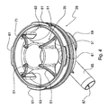
Fig. 4 is an elevation of the cup inside; -
Fig. 5 is an elevation of the bracket; -
Fig. 6 is a bottom view of the pulsation cross. - Referring to
Figs. 1 and2 , the manifold device according to the invention, generally denoted 11, substantially consists of twohollow portions coupling 17, with the interposition of a suitably shaped vacuum-tight gasket 19. - The
first portion 13 ofmanifold device 11 according to the invention, or upper portion according to the orientation ofFigs. 1 and2 , comprises acover 21, which is equipped with fournipples bracket 25 and a distributingmember 27, referred to in the art as pulsation cross. - The
second portion 15 of the device, or lower portion always according to the orientation ofFigs. 1 and2 , comprises asmall cup 29, sealinggasket 19 and preferably an external shock-absorbingring 31, acting as a protection against side shocks. - According to the invention, a
deflector member 35 is located inside volume 33 enclosed betweenportions -
Cover 21 has, besidesnipples vent hole 37, enabling introduction of a controlled amount of atmospheric air into volume 33 enclosed withinmanifold device 11, in order to enable a quick discharge of milk. Indeed, it is clear that the motor fluid pushing the transiting milk is represented by such an amount of atmospheric air entering from the outside. - Advantageously, according to the invention, the wall thickness in
portion 41 ofcover 21 wherehole 37 is formed is approximately half the thickness in the remaining cover portion, so that the hole is made substantially self-cleaning thanks to the reduced friction as air passes through it. -
Cover 21 preferably has circular shape and has a threaded, preferably blind cylindricalcentral insert 43, which is secured, for instance welded, to cover 21. Saidinsert 43 is to receive ascrew 47 intended to secure lockingbracket 25, as it will be better described hereinafter. -
Cover 21 can preferably be made of stainless steel, in a wide range of models differing from one another both in respect of the diameters ofnipples - According to the invention, a common feature of all models of
manifold device 11 consists of the different inclinations of the nipple axes in the nipple pairs provided oncover 21. Afirst nipple pair second pair - Referring to
Fig. 3 ,deflector 35 located inside volume 33 is ring shaped and has a substantially frusto-conicalcentral portion 49 intended to intercept and deflect the milk flows enteringmanifold device 11 and coming from the fournipples - Said
portion 49 has associated therewith substantially triangular radial screens 51, in the illustrated example four screens mutually spaced by 90°, intended to support the deflector with respect tocup 29 and to divide the milk flow passing through volume 33. - Turning back to
Fig. 2 , according to the invention, the shape ofdeflector member 35 is defined in the whole so that milk flowing in vertical direction, i.e. from top to bottom inFig. 2 in the direction of arrow F, is directed alonginternal walls 53 ofcup 29 and flows towards cup bottom 55 according to a substantially laminar flow condition. - Advantageously, the frusto-conical shape of
central portion 49 ofdeflector member 35, with the minor base directed towardsbottom 55 ofcup 29, i.e. downwards inFig. 2 , allows milk to flow along the shortest path inside volume 33. Moreover, such path is substantially the same for all of the four inlet jets from the fournipples - Moreover,
walls 53 ofcup 29 will be advantageously smooth and without any roughness, so as to prevent foam generation when they are licked by the milk flow directed towardsexhaust 57. Thanks to such a feature, milk jets entering volume 33 do not undergo hard frontal impacts against the inner walls of the manifold device, which impacts would hinder to some extent the optimal milk flow. Actually, as known, a breakage, if any, of the inlet milk jets, for instance because of roughness, in the presence of non-clean air coming fromvent hole 37, could contribute to creating a foam rich in bacteria, which bacteria unavoidably would reduce the quality and hence the commercial value of the milked milk, due to both the contamination and the loss of the integrity of the fat cells forming the milk. - Moreover, still according to the invention, the deflection of the milk
jets entering manifold 11 alongwalls 53 ofcup 29 caused bydeflector member 35 eliminates the risk that milk coming from a nipple goes back up towards the diametrically opposed nipple. Such a phenomenon, if present, would result in the risk of transmitting infections from one teat to another, and advantageously it is avoided thanks to the provision ofdeflector 35 shaped as described above. - Creation of a laminar milk flow along
walls 53 ofcup 29 further providesmanifold device 11 with a greater stability of the vacuum degree inside it, and this allows achieving a more regular milking, without affecting the health of the animals. This result is possible in that, insidemanifold 11 according to the invention, a central region is created, substantially corresponding to the internal volume of frusto-conical portion 49 of the deflector member, where milk does not pass. That central region acts as a lung forming a vacuum reserve, indispensable for coping with demand peaks occurring in correspondence with peaks in the flow rate of inflowing milked milk. Such a reserve allows at the same time maintaining a quick milk discharge, even at high flow rates, thereby contributing to speeding up the milking operations even in the heaviest conditions. - Referring in particular to
Figs. 2 and4 ,cup 29, which is preferably made of plastic material, which is transparent in order to allow observing the passage of milked milk inside the cup and is suitable for contact with foodstuff, is equipped in the lower portion with a supportingpad 59 of resilient material, partly received in a corresponding hollow provided incup 29. Said supportingpad 59 allows maintaining an optimum attitude ofmanifold device 11 during milking, in case the manifold arrives in contact with the ground trampled on by the cow, by preventing the manifold from laterally tilting. -
Cup 29 is equipped, at its circular end, with four wedge-shapedteeth 61 radially projecting outwards and allowing the cup to be coupled, throughbayonet coupling 17, into respective seats provided incover 21. - Moreover,
cup 29 is internally equipped with coplanarradial projections 63, in the illustrated example four projections mutually spaced by 90°, intended to retain the outermost ends ofscreens 51. - Advantageously,
cup 29 has a substantially hemispherical shape, resulting in an optimum resistance to shocks and crushing, due for instance to the fortuitous trampling on by the animals. - Always according to the invention,
exhaust 57 is advantageously associated substantially with the centre ofbottom 55 ofcup 29. Such an arrangement contributes to maximising the milk discharge speed in all working attitudes of the manifold device, and it does not cause internal milk staunching when milking has ended. - Said
exhaust 57 further includes a radially directedduct 65 extending over a length substantially comprised within the overall lateral size ofmanifold device 11. Thanks to this arrangement, saidmilk discharge duct 65 is protected from shocks. Thesame duct 65 further internally includes a set of parallelaxial fins 67. This arrangement contributes to impart an oriented laminar motion to the milkflow leaving device 11 throughduct 65, which motion increases the milk speed and hence improves the draining and the performance of the manifold device. - Turning back to
Fig. 1 ,cup 29 is moreover externally equipped withside wings 68, in the illustrated example two diametrically opposed wings, which make manual grip easier and therefore make the cup more ergonomic. - If necessary,
cup 29 can be equipped with a closure valve, internally located in the central portion, in correspondence withexhaust 57. - Referring to
Fig. 2 ,cup 29 further has anannular seat 69 intended to house shock-absorbingring 31, if any. Said shock-absorbing ring has the important function of preventing the manifold device from being damaged because of the unavoidable fortuitous shocks occurring during automatic detachment of the milking assembly. - Advantageously, according to the invention, said shock-absorbing
ring 31 interferes withbottom edge 70 ofcover 21 it is brought in contact with whenbayonet coupling 17 is being locked: This feature prevents dirt from penetrating into the interstices existing betweenportions manifold device 11. - Said shock-absorbing
ring 31 is preferably made of rubber or a thermoplastic material with a suitable hardness and geometry. - Moreover, sealing
gasket 19 is arranged betweenportions circular seat 71 formed in the upper part ofcup 29, said gasket having the important task of ensuring vacuum tightness betweencover 21 andcup 29. - Since the internal portion of
gasket 19 is licked by transiting milk, the gasket should be made of a foodstuff-compatible material, for instance thermoplastic material suitable for contact with foodstuff, having characteristics of high stability with time without release of colouring substances. - The substantially rectangular elongated cross-sectional shape of
gasket 19 is such that it ensures, besides vacuum tightness, also that no radial milk leak towards the outside occurs. - Referring to
Figs. 2 and5 , the shape ofbracket 25 is essential in order to obtain a balanced horizontal attitude of the whole milking assembly and to impart a high resistance to the stresses the whole device is subjected to in use. For this reason,bracket 25 has a substantially U-shapedcentral portion 73, which has associated therewith an upward directedfront portion 75 and a horizontally directedrear appendage 77. - Locking
bracket 25 allows securingmanifold device 11, by means of a snap-hook (not shown) inserted into an annular through opening formed atforward end 75 of the bracket, to a rope of a cylinder for the automatic detachment (not shown), of a kind known in the art and used for automatically detaching the milking assembly. -
Rear appendage 77 of lockingbracket 25 has a trapezoidal throughopening 81 and allows supporting the whole milking assembly turned downwards, i.e. turned upside down with respect to the arrangement shown inFig. 2 , through a coupling with a suitable male bracket (not shown) of stainless steel, in turn firmly secured for instance to a wall or to the structure of the milking plant. This arrangement is essential in that cleaning of the system can be optimally performed when milking has ended. - Said
bracket 25 further includes a pair of half-circular relief portions 83 in the preferably oblique, upward-directedintermediate section 85 ofU-shaped portion 73, said relief portions being intended to improve the manual grip shouldmanifold device 11 be manually used. -
Bracket 25 further has abottom base section 87 with acentral hole 89 through which blind threadedcentral insert 43, secured to cover 21, passes, and twoside holes 91 each intended to receive acentring pin 45 provided on and secured to cover 21. - Advantageously, thanks to the described arrangement,
bracket 25 can be oriented according two diametrically opposite positions aboutcentral insert 43. - Preferably,
bracket 25 is made of stainless steel. - Referring to
Figs. 1 and6 ,pulsation cross 27 has the essential function of taking the pulsation signal generated by the pulsator, by means of a suitable twin connecting tube, and of distributing such signal alternately to both barrel pairs, with respective sheaths, being part of the milking assembly. As known, the presence of vacuum alternating with atmospheric air inside the barrels imparts a cyclical movement of opening and closure on themselves to the sheaths, which movement causes milk extraction from the cow's teats. - According to the invention, the pair of
front nipples 93 inpulsation cross 27 is somewhat inclined downwards, i.e. towardscover 21 of manifold device 11: in this manner, they prevent the twin tube intended to be associated with saidfront nipples 93 from undergoing the typical, and often marked, S-shaped deviation at its end section close to the coupling with said nipples, since such tube is generally associated through resilient clamps with the underlying milk discharge tube. - A
vertical throughhole 95 is provided centrally ofpulsation cross 27 and it allows housing with acertain clearance screw 41fastening bracket 25 ontocover 21. - Such a coupling, which is partly free since it is vertically slidable along the screw, allows a vertical displacement of
pulsation cross 27 relative to cover 21, in the illustrated example a displacement of about 25 mm, as well as a certain rotation of the cross. Advantageously, thanks to such a variable attitude arrangement of the pulsation cross, during milking there is obtained an optimum attitude of the pulsation tubes associated withside nipples 97 of the pulsation cross and transmitting the pulsation signal to the barrels in the milking assembly. More particularly, thanks to such a variable attitude arrangement ofpulsation cross 27, the risk is reduced of generating tensile stresses onto the side pulsation tubes associated withnipples 97 because of particular positions the collecting device may take during milking, which stresses result in the risk that the sheath slides off the animal's teat. - Said
hole 95 is internally provided with parallelaxial ribs 96, in the illustrated example three ribs spaced apart by 120°, intended to reduce the contact friction and hence to improve sliding ofcross 27 alongscrew 47. - In order to completely cope with the different milking techniques available on the market, the pulsation cross can advantageously be manufactured according two different models. In a first model, or "standard" model, each
inclined front nipple 93 distributes successively and alternately the pulsation signal to eachside nipple pair 97. A second model, or "front rear" model, differs both geometrically and functionally from the first one in that the two inclined front nipples distribute the pulsation signal, always alternately, to the front and the rear nipples, respectively, in both side nipple pairs. - Several variants, all lying within the scope of the invention, are possible for the described manifold device.
Claims (15)
- A manifold device (11) for milking plants, comprising:- two hollow portions (13, 15) coupled with each other, a first portion being equipped with nipples (23a, 23b, 23c, 23d) for milk inflow into the device, and a second portion being equipped with an exhaust duct for milk outflow from the device,- a deflector member located inside the volume enclosed between said hollow portions, said deflector member contributing to maintaining a laminar flow of the milk passing through said volume, characterized in that:- the deflector member (35) is ring shaped and has a substantially frusto-conical central portion (49) intended to intercept and deflect the milk flows entering the device and coming from the inlet nipples, said frusto-conical portion (49) having its minor base directed towards the exhaust duct,- inside the manifold device (11) there is defined a central region, substantially corresponding to the internal volume of the frusto-conical portion (49), said central region acting as a lung forming a vacuum reserve where milk does not pass,- said frusto-conical portion (49) has associated therewith substantially triangular radial screens (51) intended to support the deflector inside the device and to divide the milk flow passing through the device,- said second portion includes a substantially hemispherical cup (29) internally equipped with coplanar radial projections (63) arranged to retain the outermost ends of the screens (51) of the deflector member (35).
- The device as claimed in claim 1, wherein said radial screens (51) and said radial projections (63) are four screens and four projections mutually spaced by 90° respectively.
- The device as claimed in claim 1 or 2, wherein cup (29) is externally equipped with side wings (68), which make manual grip easier and therefore make the cup more ergonomic.
- The device as claimed in claim 1 or 2 or 3, wherein cup (29) is equipped with a closure valve, internally located in the central portion, in correspondence with exhaust (57).
- The device as claimed in any preceding claim, wherein said first portion includes a cover (21) equipped with four nipples for milk inflow and wherein a first nipple pair (23a, 23b) is less divergent than the second nipple pair (23c, 23d).
- The device as claimed in claim 5, wherein the cover (21) is equipped with a gauged vent hole (37), the wall thickness in the cover portion (41) where said vent hole (37) is formed being approximately half the thickness in the remaining cover portion, so that the hole is made substantially self-cleaning thanks to the reduced friction as air passes through it.
- The device as claimed in claim 1, wherein the cup (29) includes an external shock-absorbing ring (31) having the function of protecting the device from shocks, and wherein said cup is externally provided at its bottom with a supporting pad (59) of resilient material.
- The device as claimed in claim 7, wherein the cup (29) further includes an annular seat (69) intended to house the shock-absorbing ring (31), said shock-absorbing ring (31) interfering with the bottom edge (70) of the cover (21) it is brought in contact with when the manifold device is closed.
- The device as claimed in claim 8, wherein the exhaust (57) are advantageously associated substantially with the centre of the bottom (55) of the cup (29), and wherein said exhaust (57) further includes a radially directed duct (65) extending over a length substantially comprised within the overall lateral size of manifold device.
- The device as claimed in claim 9, wherein said duct (65) further internally has a set of parallel axial fins (67).
- The device as claimed in any preceding claim, including a locking bracket (25) associated with said cover, said bracket having a substantially U-shaped central portion (73) which has associated therewith an upward directed front portion (75) and a horizontally directed rear appendage (77), and wherein the rear appendage (77) of the locking bracket (25) has a through opening (81) and a pair of half-circular relief portions (83) in the intermediate section (85) of the U-shaped portion (73).
- The device as claimed in claim 11, wherein the bracket (25) further has a base section (87) with a central hole (89) through which a threaded central insert (43), secured to the cover (21), passes, and two side holes (91) intended to receive each a centring pin (45) provided on and secured to the cover (21).
- The device as claimed in claim 11 or 12, wherein a pulsation cross (27) is provided having a pair of front nipples (93) and two pairs of side nipples (97), the nipples in the front nipple pair being inclined towards the cover (21) of the manifold device (11), and wherein a hole (95) is provided centrally of the pulsation cross (27) to house with a certain clearance a screw (47) securing the bracket (25) onto the cover (21), in such a manner that said cross is partly freely rotatable and slidable relative to the screw and hence relative to the cover.
- The device as claimed in any preceding claim, wherein the coupling between said two portions includes a bayonet coupling (17), and wherein a vacuum-tight gasket (19) is provided between the two portions (13, 15) of the device and is received in a circular seat (71) provided in the cup (29).
- The device as claimed in claim 13, wherein said hole (95) provided centrally of the pulsation cross is internally provided with parallel axial ribs (96) intended to reduce the contact friction and hence to improve sliding of cross (27) along screw (47).
Priority Applications (1)
| Application Number | Priority Date | Filing Date | Title |
|---|---|---|---|
| EP08425678A EP2179644B1 (en) | 2008-10-21 | 2008-10-21 | Manifold device for milking plants |
Applications Claiming Priority (1)
| Application Number | Priority Date | Filing Date | Title |
|---|---|---|---|
| EP08425678A EP2179644B1 (en) | 2008-10-21 | 2008-10-21 | Manifold device for milking plants |
Publications (2)
| Publication Number | Publication Date |
|---|---|
| EP2179644A1 EP2179644A1 (en) | 2010-04-28 |
| EP2179644B1 true EP2179644B1 (en) | 2011-06-29 |
Family
ID=40521820
Family Applications (1)
| Application Number | Title | Priority Date | Filing Date |
|---|---|---|---|
| EP08425678A Ceased EP2179644B1 (en) | 2008-10-21 | 2008-10-21 | Manifold device for milking plants |
Country Status (1)
| Country | Link |
|---|---|
| EP (1) | EP2179644B1 (en) |
Cited By (1)
| Publication number | Priority date | Publication date | Assignee | Title |
|---|---|---|---|---|
| US20230074853A1 (en) * | 2020-01-21 | 2023-03-09 | D.F. Van Staveren Holding B.V. | Spray head configured to clean teat of dairy animal |
Families Citing this family (2)
| Publication number | Priority date | Publication date | Assignee | Title |
|---|---|---|---|---|
| NZ709565A (en) | 2012-12-19 | 2017-10-27 | Delaval Holding Ab | A claw for a milking machine |
| EP3197271B1 (en) * | 2014-09-24 | 2019-08-21 | Interpuls S.P.A. | Double chamber volumetric milk meter |
Citations (2)
| Publication number | Priority date | Publication date | Assignee | Title |
|---|---|---|---|---|
| GB1160900A (en) * | 1966-09-13 | 1969-08-06 | Gascoignes Res & Dev Ltd | Improvements in or relating to Teat Cups for Milking Equipment |
| DE10132132A1 (en) * | 2001-07-03 | 2003-01-16 | Jun Jakob Maier | Milk collection unit |
Family Cites Families (9)
| Publication number | Priority date | Publication date | Assignee | Title |
|---|---|---|---|---|
| GB114033A (en) * | 1917-03-16 | 1918-03-18 | Robert Wallace | Improvements in and relating to Pulsating Apparatus for Milking Machines. |
| US4537152A (en) * | 1984-06-01 | 1985-08-27 | Dec International, Inc. | Milking claw |
| US4936254A (en) * | 1986-05-10 | 1990-06-26 | Ambic Equipment Limited | Automatic milking apparatus |
| US4807566A (en) | 1987-10-05 | 1989-02-28 | Alfa-Laval, Inc. | Milk claw |
| US6439157B1 (en) * | 1997-05-12 | 2002-08-27 | Delaval Holding Ab | Device arranged to permit an air flow from an environment to an inner space |
| NZ528893A (en) | 2003-10-13 | 2005-06-24 | Eliminator Holdings Ltd | An improved fluid treatment system |
| DE102005015916A1 (en) | 2005-04-06 | 2006-10-12 | Fritz Happel | Claw for milking machines has guide surfaces, into which milk inlets open, between which is central space |
| DE102005017094A1 (en) | 2005-04-13 | 2006-10-19 | Werner Happel | Milk collecting device used on e.g. cows, has pipe arranged inside milk collection area, in which pipe has longitudinal axis set in milking position and running parallel to space occupied by animal being milked |
| US20070272160A1 (en) * | 2006-05-10 | 2007-11-29 | Michael Berentzen | Modified milk-collecting component |
-
2008
- 2008-10-21 EP EP08425678A patent/EP2179644B1/en not_active Ceased
Patent Citations (2)
| Publication number | Priority date | Publication date | Assignee | Title |
|---|---|---|---|---|
| GB1160900A (en) * | 1966-09-13 | 1969-08-06 | Gascoignes Res & Dev Ltd | Improvements in or relating to Teat Cups for Milking Equipment |
| DE10132132A1 (en) * | 2001-07-03 | 2003-01-16 | Jun Jakob Maier | Milk collection unit |
Cited By (1)
| Publication number | Priority date | Publication date | Assignee | Title |
|---|---|---|---|---|
| US20230074853A1 (en) * | 2020-01-21 | 2023-03-09 | D.F. Van Staveren Holding B.V. | Spray head configured to clean teat of dairy animal |
Also Published As
| Publication number | Publication date |
|---|---|
| EP2179644A1 (en) | 2010-04-28 |
Similar Documents
| Publication | Publication Date | Title |
|---|---|---|
| RU2465768C2 (en) | Collector of milking machine with locking chambers | |
| WO2004030445A3 (en) | Short milk tube | |
| WO2015150807A1 (en) | A clawbowl for a milking cluster | |
| US20070272160A1 (en) | Modified milk-collecting component | |
| RU2655834C2 (en) | Milk conduit and milk-receiving member | |
| EP2179644A1 (en) | Manifold device for milking plants | |
| EP3232771B1 (en) | A teatcup | |
| US1259309A (en) | Milking-machine. | |
| CA2578350C (en) | A teatcup, and a teatcup part | |
| CA2475220C (en) | Side outlet milking claw | |
| Jones | The role of milking equipment in mastitis | |
| CA2890793C (en) | A claw for a milking machine | |
| US6401655B1 (en) | Milking claw with concave window | |
| US7617796B2 (en) | Milking claw | |
| EP1169912A1 (en) | An implement for milking animals | |
| US20140209030A1 (en) | High Capacity Milking Claw | |
| WO2012035527A1 (en) | A milking claw | |
| RU61505U1 (en) | LOW VACUUM MILKING MACHINE | |
| RU2565276C1 (en) | Two-stroke milking machine of pairwise milking | |
| RU2323568C1 (en) | Milk claw | |
| WO2005107440A1 (en) | A collector for milk downflow | |
| EP2057895A1 (en) | Automatic valve for milking installations | |
| RU2150191C1 (en) | Milking unit for high-producing cows | |
| RU124113U1 (en) | SUSPENDED PART OF THE MILKING MACHINE FOR GOATS | |
| UA28966U (en) | Collector of milking unit |
Legal Events
| Date | Code | Title | Description |
|---|---|---|---|
| PUAI | Public reference made under article 153(3) epc to a published international application that has entered the european phase |
Free format text: ORIGINAL CODE: 0009012 |
|
| 17P | Request for examination filed |
Effective date: 20091231 |
|
| AK | Designated contracting states |
Kind code of ref document: A1 Designated state(s): AT BE BG CH CY CZ DE DK EE ES FI FR GB GR HR HU IE IS IT LI LT LU LV MC MT NL NO PL PT RO SE SI SK TR |
|
| AX | Request for extension of the european patent |
Extension state: AL BA MK RS |
|
| 17Q | First examination report despatched |
Effective date: 20100504 |
|
| GRAP | Despatch of communication of intention to grant a patent |
Free format text: ORIGINAL CODE: EPIDOSNIGR1 |
|
| AKX | Designation fees paid |
Designated state(s): DE ES GB IT |
|
| GRAS | Grant fee paid |
Free format text: ORIGINAL CODE: EPIDOSNIGR3 |
|
| GRAA | (expected) grant |
Free format text: ORIGINAL CODE: 0009210 |
|
| AK | Designated contracting states |
Kind code of ref document: B1 Designated state(s): DE ES GB IT |
|
| REG | Reference to a national code |
Ref country code: GB Ref legal event code: FG4D |
|
| REG | Reference to a national code |
Ref country code: DE Ref legal event code: R096 Ref document number: 602008007932 Country of ref document: DE Effective date: 20110818 |
|
| PLBE | No opposition filed within time limit |
Free format text: ORIGINAL CODE: 0009261 |
|
| STAA | Information on the status of an ep patent application or granted ep patent |
Free format text: STATUS: NO OPPOSITION FILED WITHIN TIME LIMIT |
|
| 26N | No opposition filed |
Effective date: 20120330 |
|
| REG | Reference to a national code |
Ref country code: DE Ref legal event code: R097 Ref document number: 602008007932 Country of ref document: DE Effective date: 20120330 |
|
| PG25 | Lapsed in a contracting state [announced via postgrant information from national office to epo] |
Ref country code: ES Free format text: LAPSE BECAUSE OF FAILURE TO SUBMIT A TRANSLATION OF THE DESCRIPTION OR TO PAY THE FEE WITHIN THE PRESCRIBED TIME-LIMIT Effective date: 20111010 |
|
| PGFP | Annual fee paid to national office [announced via postgrant information from national office to epo] |
Ref country code: GB Payment date: 20231031 Year of fee payment: 16 |
|
| PGFP | Annual fee paid to national office [announced via postgrant information from national office to epo] |
Ref country code: IT Payment date: 20231024 Year of fee payment: 16 Ref country code: DE Payment date: 20231018 Year of fee payment: 16 |
|
| REG | Reference to a national code |
Ref country code: DE Ref legal event code: R119 Ref document number: 602008007932 Country of ref document: DE |
|
| GBPC | Gb: european patent ceased through non-payment of renewal fee |
Effective date: 20241021 |
|
| PG25 | Lapsed in a contracting state [announced via postgrant information from national office to epo] |
Ref country code: DE Free format text: LAPSE BECAUSE OF NON-PAYMENT OF DUE FEES Effective date: 20250501 |
|
| PG25 | Lapsed in a contracting state [announced via postgrant information from national office to epo] |
Ref country code: GB Free format text: LAPSE BECAUSE OF NON-PAYMENT OF DUE FEES Effective date: 20241021 |
|
| PG25 | Lapsed in a contracting state [announced via postgrant information from national office to epo] |
Ref country code: IT Free format text: LAPSE BECAUSE OF NON-PAYMENT OF DUE FEES Effective date: 20241021 |