EP2179253B1 - Koppelelement für ein ultraschall-durchflussmessgerät - Google Patents
Koppelelement für ein ultraschall-durchflussmessgerät Download PDFInfo
- Publication number
- EP2179253B1 EP2179253B1 EP08786025.0A EP08786025A EP2179253B1 EP 2179253 B1 EP2179253 B1 EP 2179253B1 EP 08786025 A EP08786025 A EP 08786025A EP 2179253 B1 EP2179253 B1 EP 2179253B1
- Authority
- EP
- European Patent Office
- Prior art keywords
- coupler element
- platform
- coupling element
- ultrasonic flowmeter
- piezoelement
- Prior art date
- Legal status (The legal status is an assumption and is not a legal conclusion. Google has not performed a legal analysis and makes no representation as to the accuracy of the status listed.)
- Active
Links
- 230000008878 coupling Effects 0.000 title description 68
- 238000010168 coupling process Methods 0.000 title description 68
- 238000005859 coupling reaction Methods 0.000 title description 68
- 238000005259 measurement Methods 0.000 claims description 8
- 230000002093 peripheral effect Effects 0.000 claims description 4
- 239000003292 glue Substances 0.000 claims description 3
- 230000001012 protector Effects 0.000 claims 2
- NJPPVKZQTLUDBO-UHFFFAOYSA-N novaluron Chemical compound C1=C(Cl)C(OC(F)(F)C(OC(F)(F)F)F)=CC=C1NC(=O)NC(=O)C1=C(F)C=CC=C1F NJPPVKZQTLUDBO-UHFFFAOYSA-N 0.000 description 48
- 239000000853 adhesive Substances 0.000 description 17
- 230000001070 adhesive effect Effects 0.000 description 17
- 239000010410 layer Substances 0.000 description 15
- 230000006978 adaptation Effects 0.000 description 11
- 238000004519 manufacturing process Methods 0.000 description 11
- 239000012790 adhesive layer Substances 0.000 description 8
- 239000007788 liquid Substances 0.000 description 8
- 239000012799 electrically-conductive coating Substances 0.000 description 6
- 238000002604 ultrasonography Methods 0.000 description 5
- 241001310793 Podium Species 0.000 description 4
- 239000000463 material Substances 0.000 description 4
- 238000013461 design Methods 0.000 description 3
- 238000005516 engineering process Methods 0.000 description 3
- 238000000034 method Methods 0.000 description 3
- 239000004033 plastic Substances 0.000 description 3
- 229920003023 plastic Polymers 0.000 description 3
- 229910000679 solder Inorganic materials 0.000 description 3
- 238000000576 coating method Methods 0.000 description 2
- 238000009826 distribution Methods 0.000 description 2
- 238000012545 processing Methods 0.000 description 2
- 230000000284 resting effect Effects 0.000 description 2
- 238000005476 soldering Methods 0.000 description 2
- 125000006850 spacer group Chemical group 0.000 description 2
- 240000006240 Linum usitatissimum Species 0.000 description 1
- 239000000654 additive Substances 0.000 description 1
- 230000000996 additive effect Effects 0.000 description 1
- XAGFODPZIPBFFR-UHFFFAOYSA-N aluminium Chemical compound [Al] XAGFODPZIPBFFR-UHFFFAOYSA-N 0.000 description 1
- 229910052782 aluminium Inorganic materials 0.000 description 1
- 238000005266 casting Methods 0.000 description 1
- 239000011248 coating agent Substances 0.000 description 1
- 230000000295 complement effect Effects 0.000 description 1
- 239000002131 composite material Substances 0.000 description 1
- 239000004020 conductor Substances 0.000 description 1
- 239000000356 contaminant Substances 0.000 description 1
- 230000001419 dependent effect Effects 0.000 description 1
- 238000001035 drying Methods 0.000 description 1
- 230000000694 effects Effects 0.000 description 1
- 238000011156 evaluation Methods 0.000 description 1
- 239000011521 glass Substances 0.000 description 1
- 238000009434 installation Methods 0.000 description 1
- 238000003754 machining Methods 0.000 description 1
- 238000004382 potting Methods 0.000 description 1
- 239000002243 precursor Substances 0.000 description 1
- 239000006228 supernatant Substances 0.000 description 1
- 229920001169 thermoplastic Polymers 0.000 description 1
- 239000004416 thermosoftening plastic Substances 0.000 description 1
- 230000007704 transition Effects 0.000 description 1
- -1 with overflow Chemical compound 0.000 description 1
Images


Classifications
-
- G—PHYSICS
- G01—MEASURING; TESTING
- G01F—MEASURING VOLUME, VOLUME FLOW, MASS FLOW OR LIQUID LEVEL; METERING BY VOLUME
- G01F1/00—Measuring the volume flow or mass flow of fluid or fluent solid material wherein the fluid passes through a meter in a continuous flow
- G01F1/66—Measuring the volume flow or mass flow of fluid or fluent solid material wherein the fluid passes through a meter in a continuous flow by measuring frequency, phase shift or propagation time of electromagnetic or other waves, e.g. using ultrasonic flowmeters
- G01F1/662—Constructional details
-
- G—PHYSICS
- G01—MEASURING; TESTING
- G01N—INVESTIGATING OR ANALYSING MATERIALS BY DETERMINING THEIR CHEMICAL OR PHYSICAL PROPERTIES
- G01N2291/00—Indexing codes associated with group G01N29/00
- G01N2291/02—Indexing codes associated with the analysed material
- G01N2291/028—Material parameters
- G01N2291/02836—Flow rate, liquid level
Definitions
- the present invention relates to a coupling element for an ultrasonic flowmeter.
- Ultrasonic flowmeters are widely used in process and automation technology. They allow in a simple manner, the volume flow in a pipeline to determine contactless.
- the known ultrasonic flowmeters often work according to the Doppler or the transit time difference principle.
- ultrasonic pulses are sent both in and against the flow.
- the runtime difference can be used to determine the flow velocity and, with a known diameter of the pipe section, the volume flow rate.
- ultrasonic waves of a certain frequency are coupled into the liquid and the ultrasonic waves reflected by the liquid are evaluated. From the frequency shift between the coupled and reflected waves can also determine the flow rate of the liquid.
- ultrasonic waves are generated or received with the help of so-called ultrasonic transducers.
- ultrasonic transducers are firmly attached to the pipe wall of the relevant pipe section.
- clamp-on ultrasonic flow measurement systems have become available. In these systems, the ultrasonic transducers are pressed against the pipe wall only with a tension lock.
- Such systems are for. B. from the EP-B-686 255 . US-A 44 84 478 or US-A 45 98 593 known.
- Another ultrasonic flowmeter which operates on the transit time difference principle, is from the US-A 50 52 230 known.
- the runtime is determined here by means of bursts, which are short sinusoidal ultrasonic pulses.
- the ultrasonic transducers normally consist of a piezo element, also called piezo for short, and a coupling element, also known as a coupling wedge or, more rarely, a precursor body, made of plastic.
- a piezoelectric element In the piezoelectric element, the ultrasonic waves are generated and passed over the coupling element to the pipe wall and passed from there into the liquid. Since the speeds of sound in liquids and plastics are different, the ultrasonic waves are refracted during the transition from one medium to another. The angle of refraction is determined by Snell's law. The angle of refraction is thus dependent on the ratio of the propagation velocities in the two media.
- the object of the invention is therefore to propose a cost-effective to manufacture and a compact design having sensor for an ultrasonic flowmeter.
- the essential idea of the invention is that a piezoelement is fixedly mounted on a surface of the pedestal of the coupling element facing the piezoelectric element by means of an adhesive layer. In between, an adaptation layer can be applied in the usual way.
- the surface of the pedestal or adaptation layer facing the piezoelectric element could be referred to as an adhesive surface.
- the coupling element with the pedestal is made in one piece. Due to the free space of the pedestal with respect to the outer surfaces and the inner wall of the coupling element mechanical stresses in the sensor, for example by tightening the sensor by means of a screw or by temperature fluctuations, only to a small extent up to the piezoelectric element. The function of the piezo element remains unaffected.
- Another basic idea of the invention is the use of very few components. This results in a small ultrasonic sensor with few components.
- the one-piece coupling element is manufactured or finished in one setting, so that all functional surfaces are defined with production-related very small tolerances in their size and shape and in particular in their orientation to each other.
- the device according to the invention is used particularly advantageously in flow measurement systems based on ultrasound.
- An inventive ultrasonic sensor can be used for all conceivable tube diameter and assume a corresponding size.
- the podium height PH could be about 1 to 3mm.
- Glue that flows from the pedestal to the pedestal outlet could act as an acoustic and / or mechanical bridge connecting and thus transmit acoustic signals and / or mechanical stresses on the piezo.
- the coupling element may e.g. be made by machining or by casting.
- An additive embodiment of the device according to the invention suggests that sufficiently large radii are made on the pedestal spout in order to avoid generating any notch stresses and thus preventing cracks in the material. Depending on the material and operating conditions (eg temperature), these must be adjusted accordingly.
- An adaptation layer preferably a pane, in particular of a material, such as glass and / or aluminum, thus becomes on the pedestal applied so that the then free surface of the matching layer, the adhesive surface for the application of the piezoelectric element forms.
- the thermal expansion coefficient of such adaptation layers is usually between that of the coupling element and that of the piezoelectric element.
- an advantageous embodiment of the device according to the invention suggests that the piezo element, which is applied to the pedestal of the coupling element, projects beyond the support surface of the pedestal.
- the area of the piezo element which is fastened on the pedestal is larger than the area of the pedestal on which the piezoelement is fastened, and thus projects beyond the edge of the pedestal, in particular the piezo element projects over all sides of the pedestal.
- position and area of the sound outlet are known exactly.
- the production accuracy of the pedestal is standard in the range of 1 / 100mm.
- the piezo element has a standard tolerance of 1/10 to 2/10 mm. In order to produce the piezo element also in the 1/100 mm range, it requires an enormous cost overhead.
- the embodiment of the device according to the invention provides that the pedestal has a trough-shaped depression with a peripheral border and a tub bottom, wherein the piezoelectric element facing surface of the border, the support surface for the piezo element forms, which support surface has a height HU relative to the tub bottom and wherein the trough-shaped depression is at least partially filled with adhesive.
- the tub bottom thus forms the adhesive surface.
- an adaptation layer can be applied to or in the tank bottom.
- the piezoelectric element is located on the border, ie on the tub edges.
- the tub is up to the height of the border, ie up to the height of the Podests HP, filled with glue before the piezo element is inserted.
- the adhesive loses little or no mass in the drying or curing process, ie it shrinks or shrinks according to the invention very little or not at all, so that the piezoelectric element is very little or not drawn into the tub and thereby only slightly or not deformed ,
- the adhesive layer has the same thickness over its approximately entire surface and runs parallel to the piezo.
- a precise definition of the adhesive layer is provided by the tub of the pedestal, e.g. with overflow, possible. This determines a precisely defined amount of adhesive and its distribution.
- the coupling element comprises guide elements which are distributed around the pedestal, which have approximately equal distances A to the pedestal and which have approximately equal heights HN, where HN is greater than the height of the support surface of the Podiums HP.
- the guide elements are resiliently mounted or very elastic, e.g. as thin as possible, so that its influence on the sound field is approximately zero.
- the ultrasound is transmitted according to the invention only via the pedestal in the vertical direction of the flat-mounted piezoelectric element.
- the guide elements have manufacturing technology or assembly technical advantages.
- they are worked out of the coupling element, so are an integral part. Further advantageously, they are designed as replaceable or removable after the assembly process pins, which are placed for placement in designated pin holes. Alternatively, guide lugs may be attached.
- an advantageous embodiment of the device according to the invention is that the piezoelectric element on both the side facing the pedestal, as well as on the side facing away from the pedestal the approximately approximately entire surface is electrically contacted, in particular that a wire mesh or wires are arranged with an approximately same thickness between the piezoelectric element and the support surface and / or between the piezoelectric element and the trough bottom of the pedestal.
- the wire mesh is mentioned.
- the wire mesh can also stand for a single wire or for several individual wires. It is located between the piezo element and the adhesive surface of the pedestal.
- This wire mesh is preferably made of electrically conductive material and is fixedly and / or electrically conductively connected to the piezoelectric element.
- the wire mesh in the tub of the pedestal serves as a spacer between the piezo and tub base or adhesive surface.
- the wire mesh can rest on a flat support surface of the pedestal and even serve as a pan for the defined application of the adhesive. At the same time, it retains the aforementioned tasks as a spacer and for electrical contacting of the piezo.
- a very advantageous embodiment of the device according to the invention is the fact that the coupling element has at least one further functional surface, by means of which a sensor holder is aligned around the coupling element and / or by means of which the coupling element is aligned on or on a pipe in which the measuring medium flows.
- the coupling element itself is aligned with the pipeline in which the medium to be measured flows.
- a base of the coupling element is proposed, which serves as a functional surface for alignment, which is made in a clamping with the support or adhesive surface for attaching the piezo. The angle and the relative location of the piezo to outside surfaces and other bodies of the measuring system, in particular for Piping and the medium to be measured, are determined exactly according to the small tolerances.
- the area e.g. on the tube on which the coupling element is aligned, processed accordingly.
- as further functional surfaces e.g. provided a mounting hole or a built-in geometry for a pressure piece in the coupling element.
- Another functional surface of the coupling element is the surface for attachment of the sensor holder.
- the position of the sensor holder to the coupling element very little influence on the sound field and thus on the measurement.
- This arrangement of the functional surfaces is particularly suitable for clamp-on ultrasonic measuring devices.
- the sensor holder In built-in sensors, the sensor holder is used to align the coupling element to the pipeline. In most cases, the sensor holder is materially connected to the pipeline.
- the sound exit surface in accordance with the low manufacturing tolerances, can also be precisely defined, e.g. towards the measuring medium, position.
- the coupling element has at least one further functional surface, by means of which a kink protection for the connection cable, which serves as a passage seal for the connection cable, is aligned on the coupling element.
- the anti-buckling is attached easily and accurately positioned on the coupling element by means of the functional surface.
- Particularly advantageous kink protection is sprayed as potting on the coupling element, which components and processing steps can be saved.
- the coupling element has at least one further functional surface, by means of which a connection board is aligned on the coupling element.
- a complementary embodiment of the device according to the invention is that two sensors are mounted on the pipeline in which flows the medium to be measured, which belong to a measuring system, wherein the contacting of the piezoelectric element is made on the other side of the two piezoelectric elements.
- This is particularly advantageous in the case of sensors which are mounted on the same side of the pipeline in which the medium to be measured flows, that is to say belong to a measuring system which uses the opposite pipeline wall as the reflection body.
- a variant of the device according to the invention is that a recess in the pedestal for contacting the piezoelectric element is provided and / or a larger piezo projection is provided to a particular side of the pedestal for contacting the piezoelectric element.
- an overflow is provided in the border of the pedestal, so that the adhesive layer has a well-defined thickness.
- a wire could be guided, which belongs to the wire mesh lying in the tub, e.g. is provided for contacting the piezoelectric element.
- the pedestal 2 is an integral part of the coupling element 1. It is not only made of the same material as the coupling element 1, a high-temperature thermoplastics, and is materially connected to this, for example by an adhesive connection, but the coupling element 1 with the pedestal 2 is made a body, so to speak, made from scratch.
- the pedestal 2 has a support surface 3 on which the piezoelectric element 19 (not in FIG Fig. 1 visible) is applied.
- the bearing surface 3 is in this representation at the same time the adhesive surface, whereupon the adhesive layer is applied.
- an adaptation layer 20 (not on Fig. 1 visible) or an adaptation layer is embedded in the support surface, so that the adaptation layer 20 in turn forms the adhesive surface.
- the pedestal on 2 guide elements 4 which project beyond the support surface 3 in height.
- the guide elements 4 are very elastic or spring-mounted and act as placement aids in the manufacture or assembly of the piezoelectric element.
- the guide elements 4 are integrated into the pedestal 2. Alternatively, they can be placed next to Podium 2.
- pin holes for receiving again removable pins for positioning or assembly of the piezoelectric element are possible, through which the guide elements 4 can be replaced as described.
- the coupling element 1 has a pin hole 5, which for receiving a solder pin 6 (not in Fig. 1 visible) is provided. This serves to make contact with the piezoelectric element.
- a wire mesh can be applied to the support surface 3 of the pedestal 2, which serves for contacting the piezoelectric element 19 and at the same time forms a trough for receiving the adhesive.
- the coupling element 1 is further provided with a recess 9, which is the functional surface for receiving a kink protection 10 (not in Fig. 1 visible).
- a further functional surfaces are a built-in geometry 12 for a pressure piece 13 (not in Fig. 1 visible) and a position geometry 14 (not in Fig. 1 visible).
- the recess 9 allows a simple and secure attachment of the anti-buckling 10 (not in Fig. 1 visible) so that it is exactly determined in its position.
- Positioning geometry 14 is used to apply the sensor to a sensor holder.
- Another functional surface, which is used to align the coupling element 1 on the measuring tube, can not be seen in this figure.
- Fig. 2 is a sectional view of a non-inventive coupling element 1 with anti-buckling 10 is shown.
- the anti-buckling 10 is attached to the coupling element 1.
- This bend protection 10 the cables between the sensor and evaluation of the flowmeter are protected, which are guided by the connecting cable 11.
- the cables are connected on the sensor side to the connection board 16.
- This connection board 16 is supported radially by a board holder 17 as a further functional surface and held axially between the bend protection 10 and board holder 17 of the coupling element 1.
- the board holder 17 is formed as a shoulder of the coupling element 1.
- the height HH of the inner wall 15 is correspondingly greater than the height HN of the guide elements 4 and as the height HP of the pedestal 1 plus the thickness of the piezoelectric element 19 and any matching and / or adhesive layers.
- a Schallaus- and coupling surface which also has the function of a Ausrichtgeometrie 18 for alignment of the coupling element 1 on the measuring tube, shown.
- the alignment geometry 18 can form a functional surface with the positioning geometry 14.
- the pressure piece 13 is inserted.
- the coupling element 1 can be fixed on or on a pipe.
- the terminal board 16 is located in the shoulder-shaped board holder 17 of the inner wall 15 of the coupling element 1 and is connected via a soldering 8 or riveting with the solder pin 6, which in turn is connected via a connecting cable 7 to the piezoelectric element 19.
- the piezo element itself is glued via an adaptation layer 20 with the support surface 3 of the pedestal 2.
- the adaptation layer 20 has approximately the same size as the piezoelectric element 19 in this illustration. Both the adaptation layer 20 and the piezoelectric element 19 project laterally beyond the support surface 3 of the pedestal 2.
- the height HN of the guide elements is greater than the height of the support surface HP plus the thickness of the piezoelectric element 19 and the thickness of the matching layer 20 and a thickness of the adhesive layer, not shown for reasons of clarity.
- the height HH of the inner wall 15 may be greater than the height of the guide elements 4.
- Fig. 4 shows a detailed sectional view of an embodiment of a coupling element according to the invention.
- the pedestal 2 has a trough-shaped depression 30 with a peripheral border 29 and a trough bottom 31.
- adhesive is filled up to the height of the support surface 3 '.
- a wire mesh 21 may also be used in the trough-shaped depression. This can contribute to the stability and / or be used for contacting the piezo.
- the height HU of the support surface 3 'above the tub bottom 31 is preferably one quarter of the wavelength of the ultrasound in the adhesive layer, for example, 0.2 mm, the thickness of the border 29 about half of it preferably 0.1 mm.
- An adjustment layer can be applied both to the Be applied to the bottom 31 or be integrated into the tub bottom 31, and be connected to the piezoelectric element 19 surface and firmly and thus, below the piezoelectric element 19, rest on the support surface 3 'of the border 29, which was not shown for reasons of clarity.
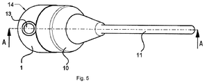
- FIG. 5 is in perspective a coupling element 1 with anti-buckling 10 for an ultrasonic flowmeter according to Fig. 2 shown.
- Fig. 6 shows a highly simplified schematic representation of a system for ultrasonic flow measurement with two ultrasonic transducers 23, 24, which are arranged offset axially parallel to the outer wall of a pipe 25.
- the measuring medium in the pipe 25 flows in the arrow direction.
- This converter pair can be operated in two different ways. Either the ultrasonic transducer 23 acts as transmitting transducer and the ultrasonic transducer as 24 as a receiver transducer or the ultrasonic transducer 23 as a receiver transducer and the ultrasonic transducer 24 as a transmitting transducer, which is measured alternately in the flow direction and against the flow direction.
- the piezoelectric elements 19 convert either electrical impulses into mechanical vibrations, the actual ultrasonic signals, or vice versa mechanical vibrations into electrical impulses.
- Both ultrasonic transducers 23, 24 are each connected via connecting lines 26 and 27 to a measuring circuit 28. About this connecting lines 26, 27, the electrical pulses are guided.
- Such measuring circuits 28 are known and not the subject of Invention.
- Fig. 7 the state of the art of contacting a piezoelectric element is presented.
- a second electrically conductive coating 33 which is applied for contacting the resting side of the piezos 19, is continuously applied up to a part of the side of the piezo 19 remote from the contact surface.
- the piezoelectric element can be used for transmitting and / or receiving vibrations, but only the area between the two coatings. Since the thus contacted piezoelectric element 19 is applied to the support surface 34 and the application is subject to large inaccuracies in the orientation, the sound exit or the sound entrance surface is not determined exactly.
- the coupling element 1 allows through a wire mesh 21 or, as in Fig. 8 According to the piezoelectric element 19 on one side of the support surface 3 of the pedestal 2 have a larger projection 35 than on other sides or a recess 36 is in the pedestal 2 admitted for contacting the piezos 19.
- the sound exit or sound entry surface is precisely determined due to the lower manufacturing tolerances of the pedestal 2, since the application tolerances no longer play a significant role.
Landscapes
- Physics & Mathematics (AREA)
- Electromagnetism (AREA)
- Fluid Mechanics (AREA)
- General Physics & Mathematics (AREA)
- Measuring Volume Flow (AREA)
Description
- Die vorliegende Erfindung betrifft ein Koppelelement für ein Ultraschall-Durchflussmessgerät.
- Ultraschall-Durchflussmessgeräte werden vielfach in der Prozess- und Automatisierungstechnik eingesetzt. Sie erlauben in einfacher Weise, den Volumendurchfluss in einer Rohrleitung berührungslos zu bestimmen.
- Die bekannten Ultraschall-Durchflussmessgeräte arbeiten häufig nach dem Doppler- oder nach dem Laufzeitdifferenz-Prinzip.
- Beim Laufzeitdifferenz-Prinzip werden die unterschiedlichen Laufzeiten von Ultraschallimpulsen relativ zur Strömungsrichtung der Flüssigkeit ausgewertet.
- Hierzu werden Ultraschallimpulse sowohl in wie auch entgegen der Strömung gesendet. Aus der Laufzeitdifferenz lässt sich die Fließgeschwindigkeit und damit bei bekanntem Durchmesser des Rohrleitungsabschnitts der Volumendurchfluss bestimmen.
- Beim Doppler-Prinzip werden Ultraschallwellen mit einer bestimmten Frequenz in die Flüssigkeit eingekoppelt und die von der Flüssigkeit reflektierten Ultraschallwellen ausgewertet. Aus der Frequenzverschiebung zwischen den eingekoppelten und reflektierten Wellen lässt sich ebenfalls die Fließgeschwindigkeit der Flüssigkeit bestimmen.
- Reflexionen in der Flüssigkeit treten jedoch nur auf, wenn Luftbläschen oder Verunreinigungen in dieser vorhanden sind, so dass dieses Prinzip hauptsächlich bei verunreinigten Flüssigkeiten Verwendung findet.
- Die Ultraschallwellen werden mit Hilfe so genannter Ultraschallwandler erzeugt bzw. empfangen. Hierfür sind Ultraschallwandler an der Rohrwandung des betreffenden Rohrleitungsabschnitts fest angebracht. Seit neuerem sind auch Clamp-on-Ultraschall-Durchflussmesssysteme erhältlich. Bei diesen Systemen werden die Ultraschallwandler nur noch mit einem Spannverschluss an die Rohrwandung gepresst. Derartige Systeme sind z. B. aus der
EP-B-686 255 US-A 44 84 478 oderUS-A 45 98 593 bekannt. - Ein weiteres Ultraschall-Durchflussmessgerät, das nach dem Laufzeitdifferenz-Prinzip arbeitet, ist aus der
US-A 50 52 230 bekannt. Die Laufzeit wird hier mittels Bursts, das sind kurze sinusförmige Ultraschallimpulse, ermittelt. - Die Ultraschallwandler bestehen normalerweise aus einem Piezoelement, auch kurz Piezo genannt, und einem Koppelelement, auch Koppelkeil oder seltener Vorlaufkörper genannt, aus Kunststoff. Im Piezoelement werden die Ultraschallwellen erzeugt und über das Koppelelement zur Rohrwandung geführt und von dort in die Flüssigkeit geleitet. Da die Schallgeschwindigkeiten in Flüssigkeiten und Kunststoffen unterschiedlich sind, werden die Ultraschallwellen beim Übergang von einem zum anderen Medium gebrochen. Der Brechungswinkel bestimmt sich nach dem Snell'schen Gesetz. Der Brechungswinkel ist somit abhängig von dem Verhältnis der Ausbreitungsgeschwindigkeiten in den beiden Medien.
- Aus dem Stand der Technik sind einer fachlich qualifizierten Person elektrische Kontaktierungen von Piezoelementen bekannt, welche Kontaktierungen auf der gegenüberliegenden Seite des einseitig flach aufgebrachten Piezoelements liegen, welches Piezoelements eine beidseitig aufgebrachte elektrisch leitfähige Beschichtung aufweist, wobei die Beschichtung der fest aufgebrachten Seite bis auf die gegenüberliegende Seite des Piezoelements führt, um dort kontaktiert zu werden. Dies führt dazu, dass die elektrisch leitfähige Beschichtung auf der gegenüberliegenden Seite des einseitig flach aufgebrachten Piezoelements nur einen Teil der Oberfläche bedeckt. So wird nur ein Teil der Piezofläche genutzt.
- Herkömmliche Koppelemente sind aus Kunststoff gefertigt und weisen eine Bohrung auf, in der das Piezoelement appliziert wird. Aus fertigungstechnischen Gründen ist diese Applikation stark toleranzbehaftet. So kann es zu einer ungleichmäßigen Verteilung des Klebstoffs kommen, wodurch das Piezoelement einen undefinierten Abstand zum Koppelelement einnimmt. Weiterhin ist die Platzierung des Piezoelements in der Bohrung des Koppelelements toleranzbehaftet, wodurch die Position der Fläche des Schallaustritts von Sensor zu Sensor schwankt. Die Fertigung eines Piezoelements und damit die Größe der Fläche des Schallaustritts des Sensors unterliegt selbst gewissen Toleranzen. Die Summe der Toleranzen ergibt einen Messfehler.
- Üblicherweise wird weiterhin ein Sensorhalter am Rohr ausgerichtet und entsprechend befestigt und das Koppelelement wird in dem Sensorhalter ausgerichtet. Dadurch addieren sich fertigungsbedingte Toleranzen einzelner, zusammengesetzter Bauteile zu einem Fehler in der Position des Piezos zur Rohrleitungswandung bzw. zum Messmedium und/oder zu einem weiteren Sensor bzw. zu dessen Piezoelement des Messsystems. Um diesen Fehler klein zu halten, müssen die einzelnen Bauteile aufwendig und damit kostenintensiv bearbeitet werden.
EP0974814 A1 offenbart den Oberbegriff des Anspruchs 1. - Durch die beschriebene Bauweise treten üblicherweise hohe mechanische Spannungen am Piezoelement auf, welche aufgrund von thermischen Ausdehnungen oder aufgrund der mechanischen Befestigung des Sensors an einer Rohrleitung entstehen und über die Wände des Koppelelements übertragen werden.
- Die Aufgabe der Erfindung besteht daher darin, einen kostengünstig herzustellenden und eine kompakte Bauweise aufweisenden Sensor für ein Ultraschall-Durchflussmessgerät vorzuschlagen.
- Die Aufgabe wird durch ein Koppelelement nach Anspruch 1 gelöst.
- Die wesentliche Idee der Erfindung besteht darin, dass ein Piezoelement auf einer, dem Piezoelement zugewandten Fläche des Podests des Koppelelements mittels einer Klebstoffschicht fest angebracht wird. Dazwischen kann in der üblichen Weise eine Anpassungsschicht aufgebracht sein. Die dem Piezoelement zugewandte Fläche des Podests bzw. der Anpassungsschicht könnte als Klebefläche bezeichnet werden. Das Koppelelement mit dem Podest wird aus einem Stück gefertigt. Durch den Freiraum des Podests gegenüber den Außenflächen und der Innenwand des Koppelelements werden mechanische Spannungen im Sensor, z.B. durch das Festmachen des Sensors mittels einer Schraube oder durch Temperaturschwankungen, nur in geringem Maße bis an das Piezoelement geleitet. Die Funktion des Piezoelements bleibt davon unbeeinflusst. Ein weiterer Grundgedanke der Erfindung besteht in der Verwendung von sehr wenigen Bauteilen. Es entsteht somit ein kleiner Ultraschallsensor mit wenigen Bauteilen.
- Gemäß einer vorteilhaften Weiterbildung der erfindungsgemäßen Vorrichtung wird das einstückige Koppelement in einer Aufspannung gefertigt bzw. endbearbeitet, so dass sämtliche Funktionsflächen mit fertigungsbedingt sehr kleinen Toleranzen in ihrer Größe und Form und insbesondere in ihrer Ausrichtung zueinander definiert sind. Besonders vorteilhaft wird die erfindungsgemäße Vorrichtung bei Durchflussmesssystemen auf Basis von Ultraschall eingesetzt. Ein erfindungsgemäßer Ultraschallsensor kann für alle denkbaren Rohrdurchmesser eingesetzt werden und eine dementsprechende Größe annehmen. Für Rohre mit einer Nennweite von bspw. ca. 50mm könnte die Podesthöhe PH ungefähr 1 bis 3mm betragen. Bei der Befestigung des Piezoelements fließt der Kleber nicht bis zum Podestauslauf. Kleber, der vom Podest bis zum Podestauslauf fließt, könnte als akustische und/oder mechanische Brücke verbindend wirken und somit akustische Signale und/oder mechanische Spannungen auf den Piezo übertragen. Das Koppelelement kann z.B. durch spanabhebende Bearbeitung oder durch Giessen hergestellt werden.
- Eine additive Ausgestaltung der erfindungsgemäßen Vorrichtung schlägt vor, dass ausreichend weite Radien am Podestauslauf gefertigt sind, um möglichst keine Kerbspannungen zu erzeugen und damit Risse im Material zu verhindern. Je nach Material und Einsatzbedingungen (z.B. Temperatur) müssen diese entsprechend angepasst sein. Eine Anpassungsschicht, bevorzugt eine Scheibe, insbesondere aus einem Werkstoff, wie z.B. Glas und/ oder Aluminium wird so auf dem Podest aufgebracht, dass die dann freie Oberfläche der Anpassungsschicht, die Klebefläche für das Aufbringen des Piezoelements bildet. Der thermische Ausdehnungskoeffizient solcher Anpassungsschichten liegt meist zwischen dem des Koppelements und dem des Piezoelements.
- Eine vorteilhafte Ausgestaltung der erfindungsgemäßen Vorrichtung schlägt vor, dass das Piezoelement, welches auf dem Podest des Koppelelements appliziert wird, über die Auflagefläche des Podests hinaus ragt. Die Fläche des Piezoelements, welche auf dem Podest befestigt wird, ist größer als die Fläche des Podests, auf der das Piezoelement befestigt wird, und steht damit über den Rand des Podests über, insbesondere steht das Piezoelement über alle Seiten des Podests über. Somit sind Position und Fläche des Schallaustritts genau bekannt. Die Fertigungsgenauigkeit des Podests liegt standartgemäß im Bereich von 1/100mm. Zum Vergleich hat das Piezoelement eine Standarttoleranz von 1/10 bis 2/10mm. Um das Piezoelement ebenfalls im 1/100mm-Bereich zu fertigen, bedarf es eines enormen Kostenmehraufwands. Um ein Piezoelement mit einer Toleranz im Bereich von 1/100mm auf einer Fläche zu applizieren, bedarf es einer hochgenauen und sehr aufwendigen und damit kostenintensiven Technologie. Diese ist bei der Montage der erfindungsgemäßen Vorrichtung nicht nötig, da der Piezo auf den Seiten des Podests unterschiedlich weit überstehen darf. Die Fläche des Schallaustritts wird erfindungsgemäß über die Podestfläche definiert.
- Die Ausgestaltung der erfindungsgemäßen Vorrichtung sieht vor, dass das Podest eine wannenförmige Vertiefung mit einer umfänglichen Umrandung und einem Wannenboden aufweist, wobei die dem Piezoelement zugewandte Fläche der Umrandung, die Auflagefläche für das Piezoelement bildet, welche Auflagefläche eine Höhe HU gegenüber dem Wannenboden aufweist und wobei die wannenförmige Vertiefung mindestens teilweise mit Klebstoff gefüllt ist. Der Wannenboden bildet somit die Klebefläche. Allerdings kann auch hier eine Anpassungsschicht auf bzw. in dem Wannenboden aufgebracht sein. Das Piezoelement liegt auf der Umrandung, also auf den Wannenrändern auf. Die Wanne wird bis zur Höhe der Umrandung, also bis zur Höhe des Podests HP, mit Klebstoff aufgefüllt, bevor das Piezoelement eingebracht wird. Der Klebstoff verliert beim Trocknungs- bzw. Aushärtungsprozess wenig oder keine Masse, d.h. er schwindet bzw. schrumpft erfindungsgemäß sehr wenig oder überhaupt nicht, so dass das Piezoelement nur sehr wenig oder überhaupt nicht in die Wanne hineingezogen und dabei nur geringfügig oder überhaupt nicht verformt wird.
- Nach einer sehr vorteilhaften Ausführungsform der erfindungsgemäßen Vorrichtung weist die Klebstoffschicht über ihre näherungsweise gesamte Fläche die gleiche Dicke auf und verläuft parallel zum Piezo. Eine genaue Definition der Klebstoffschicht ist durch die Wanne des Podests, z.B. mit Überlauf, möglich. Dadurch wird eine genau definierte Klebstoffmenge und deren Verteilung bestimmt.
- Gemäß einer vorteilhaften Ausführungsform der erfindungsgemäßen Vorrichtung wird vorgeschlagen, dass das Koppelement Führungselemente aufweist, welche um das Podest verteilt sind, welche näherungsweise gleiche Abstände A zu dem Podest aufweisen und welche näherungsweise gleiche Höhen HN aufweisen, wobei HN größer ist als die Höhe der Auflagefläche des Podests HP. Dabei sind die Führungselemente federnd gelagert bzw. sehr elastisch, z.B. möglichst dünn, so dass ihr Einfluss auf das Schallfeld näherungsweise Null ist. Der Ultraschall wird erfindungsgemäß nur über das Podest in die senkrechte Richtung des flach aufgebrachten Piezoelements übertragen. Die Führungselemente haben Fertigungstechnische bzw. Bestückungstechnische Vorteile. Vorteilhaft sind sie aus dem Koppelelement herausgearbeitet, sind also integraler Bestandteil. Weiterhin vorteilhaft sind sie als austauschbare bzw. nach dem Bestückungsprozess entfernbare Stifte ausgebildet, die zur Bestückung in dafür vorgesehene Stiftlöcher platziert werden. Alternativ können auch Führungsnasen angebracht sein.
- Eine vorteilhafte Ausführungsform der erfindungsgemäßen Vorrichtung besteht darin, dass das Piezoelement sowohl auf der dem Podest zugewandten Seite, als auch auf der dem Podest abgewandten Seite über die jeweils näherungsweise gesamte Fläche elektrisch kontaktiert wird, insbesondere dass ein Drahtgeflecht bzw. Drähte mit einer näherungsweise gleichen Dicke zwischen dem Piezoelement und der Auflagefläche und/oder zwischen dem Piezoelement und dem Wannenboden des Podests angeordnet sind. Im Nachfolgenden ist von dem Drahtgeflecht die Rede. Das Drahtgeflecht kann auch stellvertretend für einen einzelnen Draht oder für mehrere einzelne Drähte stehen. Es ist zwischen dem Piezoelement und der Klebefläche des Podests angeordnet. Dieses Drahtgeflecht besteht bevorzugt aus elektrisch leitendem Material und ist mit dem Piezoelement fest und/oder elektrisch leitend verbunden. Durch das Überstehen des Piezos über die Auflagefläche und/oder durch die Anbringung von dem Drahtgeflecht ist es möglich, beide Seiten des Piezos direkt zu kontaktieren und somit die gesamte Fläche des Piezos zu nutzen. Zusätzlich dient das Drahtgeflecht in der Wanne des Podests als Abstandshalter zwischen Piezo und Wannenboden bzw. Klebefläche. Alternativ zur Wanne des Podests, mittels der Umrandung, kann das Drahtgeflecht auf einer flachen Auflagefläche des Podests aufliegen und selbst als Wanne zum definierten Aufbringen des Klebstoffs dienen. Gleichzeitig behält es die vorgenannten Aufgaben als Abstandshalter und zur elektrischen Kontaktierung des Piezos.
- Eine sehr vorteilhafte Ausgestaltung der erfindungsgemäßen Vorrichtung ist darin zu sehen, dass das Koppelelement mindestens eine weitere Funktionsfläche aufweist, mittels derer ein Sensorhalter um das Koppelelement ausgerichtet wird und/oder mittels derer das Koppelelement auf bzw. an einer Rohrleitung ausgerichtet wird, in welcher das zu messende Medium strömt. Erfindungsgemäß wird das Koppelelement selbst an der Rohrleitung, in welcher das zu messende Medium strömt, ausgerichtet. Eine Grundfläche des Koppelelements wird vorgeschlagen, die als Funktionsfläche zur Ausrichtung dient, welche in einer Aufspannung mit der Auflage- bzw. Klebefläche zum Anbringen des Piezos gefertigt ist. Der Winkel und der relative Ort des Piezos zu Außenflächen und anderen Körpern des Messsystems, insbesondere zur Rohrleitung und zum Messmedium, sind, entsprechend der kleinen Toleranzen, genau bestimmt.
- Besonders vorteilhaft ist zusätzlich zur Grundfläche des Koppelelements die Fläche, z.B. auf dem Rohr, auf welcher das Koppelelement ausgerichtet wird, entsprechend bearbeitet. Zur Befestigung des ausgerichteten Koppelelements sind als weitere Funktionsflächen z.B. eine Befestigungsbohrung oder eine Einbaugeometrie für ein Druckstück im Koppelelement vorgesehen.
- Eine weitere Funktionsfläche des Koppelelements stellt die Fläche zur Anbringung des Sensorhalters dar. Somit ist die Position des Sensorhalters um das Koppelelement, der geringen Fertigungstoleranzen entsprechend, exakt definiert, insbesondere mit bekanntem, erfindungsgemäß sehr geringem, Einfluss auf das Schallfeld und damit auf die Messung. Diese Anordnung der Funktionsflächen ist insbesondere für Clamp-On Ultraschallmessgeräte geeignet. Bei Einbausensoren dient der Sensorhalter zur Ausrichtung des Koppelelements zur Rohrleitung hin. Meist ist der Sensorhalter dabei mit der Rohrleitung stoffschlüssig verbunden. Durch entsprechende Bearbeitung des Sensorhalters lässt sich die Schallaustrittsfläche, der geringen Fertigungstoleranzen entsprechend, ebenso exakt, z.B. zum Messmedium hin, positionieren.
- Eine weitere sehr vorteilhafte Ausgestaltung der erfindungsgemäßen Vorrichtung besteht darin, dass das Koppelelement mindestens eine weitere Funktionsfläche aufweist, mittels derer ein Knickschutz für die Anschlusskabel, welcher als Durchgangsdichtung für die Anschlusskabel dient, am Koppelelement ausgerichtet wird. Der Knickschutz wird einfach und positionsgenau auf das Koppelelement mittels der Funktionsfläche aufgesteckt. Besonders vorteilhaft wird der Knickschutz als Verguss auf das Koppelelement aufgespritzt, wodurch Bauteile und Bearbeitungsschritte eingespart werden.
- Eine weitere sehr Vorteilhafte Ausgestaltung der erfindungsgemäßen Vorrichtung schlägt vor, dass das Koppelelement mindestens eine weitere Funktionsfläche aufweist, mittels derer eine Anschlussplatine am Koppelelement ausgerichtet wird.
- Eine ergänzende Ausführung der erfindungsgemäßen Vorrichtung ist, dass zwei Sensoren, die auf der Rohrleitung, in welcher das zu messende Medium strömt, angebracht sind, welche zu einem Messsystem gehören, wobei die Kontaktierung des Piezoelements auf der jeweils anderen Seite der zwei Piezoelemente vorgenommen ist. Dies ist insbesondere bei Sensoren von Vorteil, die auf der gleichen Seite der Rohrleitung, in welcher das zu messende Medium strömt, angebracht sind, also zu einem Messsystem gehören, welches die gegenüberliegende Rohrleitungswand als Reflektionskörper nutzt.
- Eine Variante der erfindungsgemäßen Vorrichtung besteht darin, dass eine Aussparung im Podest zur Kontaktierung des Piezoelements vorgesehen ist und/oder ein größerer Piezoüberstand zu einer bestimmten Seite des Podests zur Kontaktierung des Piezoelements vorgesehen ist.
- Eine weitere Variante der erfindungsgemäßen Vorrichtung besteht darin, dass ein Überlauf in der Umrandung des Podests vorgesehen ist, damit die Klebstoffschicht eine genau definierte Dicke besitzt. Durch diesen Überlauf könnte ein Draht geführt werden, der zu dem in der Wanne liegenden Drahtgeflecht gehört, der z.B. zur Kontaktierung des Piezoelements vorgesehen ist.
- Die Erfindung wird anhand der nachfolgenden Figuren näher erläutert.
-
Fig. 1 zeigt perspektivisch ein nicht erfindungsgemäßes Koppelelement für ein Ultraschall-Durchflussmessgerät. -
Fig. 2 zeigt eine Schnittdarstellung eines nicht erfindungsgemäßen Koppelelements mit Knickschutz. -
Fig. 3 zeigt eine Detaildarstellung eines Koppelelements mit Knickschutz gemäßFig. 2 . -
Fig. 4 zeigt eine Schnittdarstellung eines erfindungsgemäßen Koppelelements. -
Fig. 5 zeigt perspektivisch ein Koppelelement mit Knickschutz für ein Ultraschall-Durchflussmessgerät gemäßFig. 2 . -
Fig. 6 zeigt eine Schematische Darstellung eines Systems zur Ultraschall-Durchflussmessung. -
Fig. 7 zeigt den Stand der Technik einer Kontaktierung eines flach aufliegenden Piezoelements. -
Fig. 8 zeigt eine Schnittdarstellung eines weiteren erfindungsgemäßen Koppelelements. - In der perspektivischen Darstellung der
Fig. 1 ist ein Koppelelement 1 mit einem Podest 2 zu sehen. Das Podest 2 ist integraler Bestandteil des Koppelements 1. Es besteht nicht nur aus dem gleichen Material wie das Koppelelement 1, einem Hochtemperatur-Thermoplasten, und ist mit diesem, z.B. durch eine Klebeverbindung stoffschlüssig verbunden, sondern das Koppelelement 1 mit dem Podest 2 ist aus einem Körper, sozusagen aus dem Vollen, gefertigt. - Das Podest 2 weist eine Auflagefläche 3 auf, auf der das Piezoelement 19 (nicht in
Fig. 1 sichtbar) appliziert wird. Die Auflagefläche 3 ist in dieser Darstellung gleichzeitig die Klebefläche, worauf die Klebstoffschicht aufgetragen wird. Alternativ kann auf die Auflagefläche 3 eine Anpassungsschicht 20 (nicht aufFig. 1 sichtbar) aufgebracht sein oder eine Anpassungsschicht ist in die Auflagefläche eingelassen, so dass die Anpassungsschicht 20 ihrerseits die Klebefläche bildet. - Neben der Auflagefläche 3 weist das Podest 2 Führungselemente 4 auf, welche die Auflagefläche 3 in der Höhe überragen. Die Führungselemente 4 sind sehr elastisch oder federnd gelagert und fungieren als Bestückungshilfen bei der Fertigung bzw. der Montage des Piezoelements. In diesem Ausführungsbeispiel sind die Führungselemente 4 in das Podest 2 integriert. Alternativ können sie neben dem Podest 2 platziert sein. Außer den gezeigten Führungselementen 4 sind Stiftlöcher zur Aufnahme wieder entfernbarer Stifte zur Positionierung bzw. zur Montage des Piezoelements möglich, durch welche die Führungselemente 4 wie beschrieben ersetzt werden können.
- Ferner hat das Koppelelement 1 ein Stiftloch 5, welches zur Aufnahme eines Lötstifts 6 (nicht in
Fig. 1 sichtbar) vorgesehen ist. Dieser dient der Kontaktierung des Piezoelements. Alternativ kann auf der Auflagefläche 3 des Podests 2 ein Drahtgeflecht aufgebracht sein, welches zur Kontaktierung des Piezoelements 19 dient und gleichzeitig eine Wanne zur Aufnahme des Klebstoffs bildet. - Das Koppelelement 1 ist weiterhin mit einem Einstich 9 versehen, welcher die Funktionsfläche für die Aufnahme eines Knickschutzes 10 (nicht in
Fig. 1 sichtbar) bildet. Als weitere Funktionsflächen sind eine Einbaugeometrie 12 für ein Druckstück 13 (nicht inFig. 1 sichtbar) und eine Positioniergeometrie 14 (nicht inFig. 1 sichtbar) gezeigt. Der Einstich 9 ermöglicht ein einfaches und sicheres Anbringen des Knickschutzes 10 (nicht inFig. 1 sichtbar), damit dieser in seiner Position exakt bestimmt ist. An die Positioniergeometrie 14 wird der Sensor an einen Sensorhalter angelegt. Eine weitere Funktionsfläche, welche zur Ausrichtung des Koppelelements 1 am Messrohr genutzt wird, ist in dieser Abbildung nicht zu sehen. - In
Fig. 2 ist eine Schnittdarstellung eines nicht erfindungsgemäßen Koppelelements 1 mit Knickschutz 10 gezeigt. Der Knickschutz 10 ist auf das Koppelelement 1 aufgesteckt. Durch diesen Knickschutz 10 werden die Kabel zwischen Sensor und Auswerteeinheit des Durchflussmessgeräts geschützt, welche durch das Verbindungskabel 11 geführt werden. Die Kabel sind sensorseitig mit der Anschlussplatine 16 verbunden. Diese Anschlussplatine 16 wird radial durch einen Platinenhalter 17 als weitere Funktionsfläche gestützt und axial zwischen Knickschutz 10 und Platinenhalter 17 des Koppelelements 1 festgehalten. Der Platinenhalter 17 ist als Schulter des Koppelelements 1 ausgebildet. Die Höhe HH der Innenwand 15 ist entsprechend größer als die Höhe HN der Führungselemente 4 und als die Höhe HP des Podests 1 plus der Dicke des Piezoelements 19 und eventuellen Anpassungs- und/oder Klebstoffschichten. - Als weitere Funktionsfläche ist eine Schallaus- und Einkoppelfläche, die auch die Funktion einer Ausrichtgeometrie 18 zur Ausrichtung des Koppelelements 1 am Messrohr hat, gezeigt. Je nach Bauart des Koppelelements 1 kann die Ausrichtgeometrie 18 eine Funktionsfläche mit der Positioniergeometrie 14 bilden. In der Einbaugeometrie 12 ist das Druckstück 13 eingesetzt. Damit lässt sich das Koppelelement 1 auf bzw. an einer Rohrleitung festmachen.
- Weitere Merkmale sind der Detailzeichnung
Fig. 3 zu entnehmen. - Die Anschlussplatine 16 liegt in dem schulterartig ausgebildeten Platinenhalter 17 der Innenwand 15 des Koppelelements 1 und ist über eine Lötung 8 oder Nietung mit dem Lötstift 6 verbunden, der seinerseits über einem Anschlusskabel 7 mit dem Piezoelement 19 verbunden ist. Dadurch ist der elektrische Kontakt zwischen Piezoelement 19 und Anschlussplatine 16 hergestellt. Das Piezoelement selbst ist über eine Anpassungsschicht 20 mit der Auflagefläche 3 des Podests 2 verklebt. Die Anpassungsschicht 20 hat in dieser Darstellung näherungsweise die gleiche Größe wie das Piezoelement 19. Sowohl Anpassungsschicht 20, als auch Piezoelement 19 stehen seitlich über die Auflagefläche 3 des Podests 2 über.
- Am Podestauslauf und an den Ausläufen der Führungselementen 4 sind großzügige Radien 22 vorgesehen, damit keine Kerbspannungen auftreten und sonstige mechanische Spannungen nicht zu Bauteilen in der näheren Umgebung ein- oder weitergeleitet werden. Die Höhe HN der Führungselemente ist größer als die Höhe der Auflagefläche HP plus der Dicke des Piezoelements 19 und der Dicke der Anpassungsschicht 20 und einer aus Gründen der Übersichtlichkeit nicht dargestellten Dicke der Klebstoffschicht. Die Höhe HH der Innenwand 15 kann größer als die Höhe der Führungselemente 4 sein.
-
Fig. 4 zeigt eine detaillierte Schnittdarstellung eines Ausführungsbeispiels eines erfindungsgemäßen Koppelelements. Das Podest 2 weist eine wannenförmige Vertiefung 30 mit einer umfänglichen Umrandung 29 und einem Wannenboden 31 auf. In der wannenförmigen Vertiefung 30 wird Klebstoff bis zur Höhe Auflagefläche 3' gefüllt. Ein Drahtgeflecht 21 kann ebenfalls in der wannenförmigen Vertiefung eingesetzt sein. Dieses kann zur Stabilität beitragen und/oder zur Kontaktierung des Piezos genutzt werden. Die Höhe HU der Auflagefläche 3' über dem Wannenboden 31 beträgt bevorzugt ein Viertel der Wellenlänge des Ultraschalls in der Klebeschicht, z.B. 0.2mm die Dicke der Umrandung 29 etwa die Hälfte davon bevorzugt 0,1mm. Eine Anpassungsschicht kann sowohl auf den Wannenboden 31 appliziert sein bzw. in den Wannenboden 31 integriert sein, als auch mit dem Piezoelement 19 flächig und fest verbunden sein und damit, unter dem Piezoelement 19, auf der Auflagefläche 3' der Umrandung 29 aufliegen, was aus Übersichtlichkeitsgründen nicht dargestellt wurde. - In
Fig. 5 ist perspektivisch ein Koppelelement 1 mit Knickschutz 10 für ein Ultraschall-Durchflussmessgerät gemäßFig. 2 gezeigt. -
Fig. 6 zeigt eine stark vereinfachte schematische Darstellung eines Systems zur Ultraschall-Durchflussmessung mit zwei Ultraschallwandlern 23, 24, die auf der Außenwand einer Rohrleitung 25 achsparallel versetzt angeordnet sind. Das Messmedium in der Rohrleitung 25 fließt in Pfeilrichtung. - Dieses Wandlerpaar kann auf zwei unterschiedliche Weisen betrieben werden. Entweder wirkt der Ultraschallwandler 23 als Sendewandler und der Ultraschallwandler als 24 als Empfängerwandler oder der Ultraschallwandler 23 als Empfängerwandler und der Ultraschallwandler 24 als Sendewandler, wodurch abwechselnd in Strömungsrichtung bzw. entgegen der Strömungsrichtung gemessen wird.
- Jeder der Ultraschallwandler 23 bzw. 24 besteht aus jeweils einem erfindungsgemäßen Koppelelement 1 mit Piezoelement 19, das die Ultraschallsignale unter einem von 90° verschiedenen Winkel α entweder in die Wandung der Rohrleitung 25 ein- bzw. auskoppelt. Der Winkel α ist so gewählt, dass das an der gegenüberliegenden Wandung der Rohrleitung 25 reflektierte Signal auf den jeweils anderen Ultraschallwandler trifft.
- Die Piezoelemente 19 wandeln dabei entweder elektrische Impulse in mechanische Schwingungen, die eigentlichen Ultraschallsignale, oder umgekehrt mechanische Schwingungen in elektrische Impulse um.
- Beide Ultraschallwandler 23, 24 sind jeweils über Anschlussleitungen 26 bzw. 27 mit einer Messschaltung 28 verbunden. Über diese Anschlussleitungen 26, 27 werden die elektrischen Impulse geführt. Derartige Messschaltungen 28 sind bekannt und nicht Gegenstand der Erfindung.
- Mit dem erfindungsgemäßen Koppelelement ist eine flächige Anlage der Ultraschallwandler gegeben und damit der Winkel zur Rohrleitung sehr genau bestimmt. Der Abstand x der beiden Ultraschallwandler und der Winkel α des Signals bestimmen wesentlich die Messgenauigkeit der Messanordnung. Mit dem erfindungsgemäßen Koppelelement lassen sich diese Parameter sehr präzise einstellen.
- Neben der Ausrichtung der Messanordnung spielen Streuverluste und Reflexionen des Ultraschallsignals eine wichtige Rolle in der Ultraschall-Durchflussmessung. Auch hier ist eine Minimierung beider Effekte im Sensor und an dessen Grenzflächen zum Stand der Technik durch das erfindungsgemäße Koppelelement gegeben.
- In
Fig. 7 ist der Stand der Technik der Kontaktierung eines Piezoelements vorgestellt. Dadurch dass das Piezoelement 19 flach auf einer Auflagefläche 34 liegt, ist die Kontaktierung dieser Seite nicht möglich. Daher bedeckt eine erste elektrisch leitende Beschichtung 32, die auf der auflageflächeabgewandten Seite des Piezos aufgebracht ist, nur einen Teil der Piezofläche. Eine zweite elektrisch leitende Beschichtung 33, die zur Kontaktierung der aufliegenden Seite des Piezos 19 aufgebracht ist, wird durchgehend bis zu einem Teil der auflageflächeabgewandten Seite des Piezos 19 aufgetragen. Somit ist nicht das gesamte Piezoelement zum Senden und/oder Empfangen von Schwingungen nutzbar, sondern lediglich die Fläche zwischen beiden Beschichtungen. Da das so kontaktierte Piezoelement 19 auf der Auflagefläche 34 appliziert ist und die Applikation mit großen Ungenauigkeiten in der Ausrichtung behaftet ist, ist die Schallaustritts- bzw. die Schalleintrittsfläche nicht genau bestimmt. - Das erfindungsgemäße Koppelelement 1 erlaubt durch ein Drahtgeflecht 21 oder, wie in
Fig. 8 dargestellt, durch das Überstehen des Piezos 19 über die Auflagefläche eine beidseitige, vollflächige Kontaktierung des Piezos 19. Erfindungsgemäß kann dabei das Piezoelement 19 auf einer Seite der Auflagefläche 3 des Podests 2 einen größeren Überstand 35 haben als auf anderen Seiten oder eine Aussparung 36 ist in dem Podest 2 zur Kontaktierung des Piezos 19 eingelassen. Die Schallaustritts- bzw. Schalleintrittsfläche ist aufgrund der geringeren Fertigungstoleranzen des Podests 2 genau bestimmt, da die Applikationstoleranzen keine wesentliche Rolle mehr spielen. -
- 1.
- Koppelelement
- 2.
- Podest
- 3.
- Auflagefläche
- 4.
- Führungselemente
- 5.
- Stiftloch
- 6.
- Lötstift
- 7.
- Anschlusskabel
- 8.
- Lötung
- 9.
- Einstich
- 10.
- Knickschutz
- 11.
- Verbindungskabel
- 12.
- Einbaugeometrie
- 13.
- Druckstück
- 14.
- Positioniergeometrie
- 15.
- Innenwand
- 16.
- Anschlussplatine
- 17.
- Platinenhalter
- 18.
- Ausrichtgeometrie
- 19.
- Piezoelement
- 20.
- Anpassungsschicht
- 21.
- Drahtgeflecht
- 22.
- Radien
- 23.
- Ultraschallwandler
- 24.
- Ultraschallwandler
- 25.
- Rohrleitung
- 26.
- Anschlussleitung
- 27.
- Anschlussleitung
- 28.
- Messschaltung
- 29.
- Umrandung
- 30.
- wannenförmige Vertiefung
- 31.
- Wannenboden
- 32.
- elektrisch leitende Beschichtung
- 33.
- elektrisch leitende Beschichtung
- 34.
- Piezoauflagefläche
- 35.
- Piezoüberstand
- 36.
- Aussparung
Claims (8)
- Koppelelement für ein Ultraschall-Durchflussmessgerät, welches ein Podest (2) mit einer Auflagefläche (3, 3') aufweist, auf welcher ein Piezoelement (19) appliziert ist und welches Podest (2) integraler Bestandteil des Koppelelements (1) ist,
dadurch gekennzeichnet,
dass das Podest (2) eine wannenförmige Vertiefung (30) mit einer umfänglichen Umrandung (29) und einem Wannenboden (31) aufweist, wobei die dem Piezoelement (19) zugewandte Fläche der Umrandung (29) des Podests (2), die Auflagefläche (3, 3') für das Piezoelement (19) bildet, welche Auflagefläche (3, 3') eine Höhe (HU) gegenüber dem Wannenboden (31) aufweist und wobei die wannenförmige Vertiefung (30) mindestens teilweise mit Klebstoff gefüllt ist. - Koppelelement für ein Ultraschall-Durchflussmessgerät nach Anspruch 1,
dadurch gekennzeichnet,
dass das Piezoelement (19), welches auf dem Podest (2) des Koppelelements (1) appliziert wird, über die Auflagefläche (3, 3') des Podests (2) hinaus ragt. - Koppelelement für ein Ultraschall-Durchflussmessgerät nach Ansprüchen 1 bis 2,
dadurch gekennzeichnet,
dass das Koppelement (1) Führungselemente (4) aufweist, welche um das Podest (2) verteilt sind, welche näherungsweise gleiche Abstände A zu dem Podest (2) aufweisen und welche näherungsweise gleiche Höhen (HN) aufweisen, wobei die Höhen (HN) größer sind als die Höhe (HP) der Auflagefläche (3, 3') des Podests (2). - Koppelelement für ein Ultraschall-Durchflussmessgerät nach Ansprüchen 1 bis 3,
dadurch gekennzeichnet,
dass das Piezoelement (19) sowohl auf der dem Podest (2) zugewandten Fläche, als auch auf der dem Podest abgewandten Fläche über die jeweils näherungsweise gesamte Fläche elektrisch kontaktiert ist. - Koppelelement für ein Ultraschall-Durchflussmessgerät nach Ansprüchen 1 bis 4,
dadurch gekennzeichnet,
dass ein Drahtgeflecht (21) bzw. Drähte mit einer näherungsweise gleichen Dicke zwischen dem Piezoelement (19) und der Auflagefläche (3, 3') und/oder zwischen dem Piezoelement (19) und dem Wannenboden (31) des Podests (2) angeordnet sind. - Koppelelement für ein Ultraschall-Durchflussmessgerät nach Ansprüchen 1 bis 5,
dadurch gekennzeichnet,
dass das Koppelelement (1) mindestens eine erste Funktionsfläche (14) aufweist, mittels der ein Sensorhalter um das Koppelelement (1) ausrichtbar ist und/oder mittels der das Koppelelement (1) auf bzw. an einer Rohrleitung (25) ausrichtbar ist, in welcher das zu messende Medium strömt. - Koppelelement für ein Ultraschall-Durchflussmessgerät nach Ansprüchen 1 bis 6,
dadurch gekennzeichnet,
dass das Koppelelement (1) mindestens eine zweite Funktionsfläche (9) aufweist, mittels der ein Knickschutz (10) für die Anschlusskabel, welcher als Durchgangsdichtung für die Anschlusskabel dient, am Koppelelement (1) ausrichtbar ist. - Koppelelement für ein Ultraschall-Durchflussmessgerät nach Ansprüchen 1 bis 7,
dadurch gekennzeichnet,
dass das Koppelelement (1) mindestens eine dritte Funktionsfläche (17) aufweist, mittels der eine Anschlussplatine (16) am Koppelelement (1) ausrichtbar ist.
Applications Claiming Priority (2)
| Application Number | Priority Date | Filing Date | Title |
|---|---|---|---|
| DE102007039016A DE102007039016A1 (de) | 2007-08-17 | 2007-08-17 | Koppelelement für ein Ultraschall-Durchflussmessgerät |
| PCT/EP2008/058968 WO2009024403A1 (de) | 2007-08-17 | 2008-07-10 | Koppelelement für ein ultraschall-durchflussmessgerät |
Publications (2)
| Publication Number | Publication Date |
|---|---|
| EP2179253A1 EP2179253A1 (de) | 2010-04-28 |
| EP2179253B1 true EP2179253B1 (de) | 2018-01-03 |
Family
ID=39745444
Family Applications (1)
| Application Number | Title | Priority Date | Filing Date |
|---|---|---|---|
| EP08786025.0A Active EP2179253B1 (de) | 2007-08-17 | 2008-07-10 | Koppelelement für ein ultraschall-durchflussmessgerät |
Country Status (4)
| Country | Link |
|---|---|
| US (1) | US8408072B2 (de) |
| EP (1) | EP2179253B1 (de) |
| DE (1) | DE102007039016A1 (de) |
| WO (1) | WO2009024403A1 (de) |
Families Citing this family (7)
| Publication number | Priority date | Publication date | Assignee | Title |
|---|---|---|---|---|
| DE102010063538A1 (de) | 2010-12-20 | 2012-06-21 | Endress + Hauser Flowtec Ag | Ultraschall-Durchflussmessgrät |
| US9244090B2 (en) * | 2012-12-18 | 2016-01-26 | Trail Tech, Inc. | Speed sensor assembly |
| DE102013104542B4 (de) | 2013-05-03 | 2015-04-09 | Endress + Hauser Flowtec Ag | Koppelelement, Ultraschallwandler und Ultraschall- Durchflussmessgerät |
| DE102013104544B4 (de) * | 2013-05-03 | 2015-03-12 | Endress + Hauser Flowtec Ag | Ultraschallwandler und Ultraschall-Durchflussmessgerät |
| JP6454219B2 (ja) * | 2015-05-14 | 2019-01-16 | 株式会社キーエンス | 超音波流量スイッチ |
| SE1950109A1 (en) * | 2019-01-30 | 2020-06-30 | Labtrino Ab | Coupling member for clamp on flow metering |
| FR3102304B1 (fr) * | 2019-10-17 | 2021-10-15 | Sagemcom Energy & Telecom Sas | Support de cellule piézoélectrique de transducteur ultrasonore |
Family Cites Families (18)
| Publication number | Priority date | Publication date | Assignee | Title |
|---|---|---|---|---|
| US4333352A (en) | 1980-10-14 | 1982-06-08 | Leeds & Northrup Company | Injection-molded Doppler flowmeter transducer assembly |
| FI67627C (fi) | 1981-10-19 | 1985-04-10 | Eino Haerkoenen | Foerfarande och anordning foer maetning av stroemningshastigheten i stroemmen av uppslamningar genom utnyttjandet av ultraljud |
| US4598593A (en) | 1984-05-14 | 1986-07-08 | The United States Of America As Represented By The United States Department Of Energy | Acoustic cross-correlation flowmeter for solid-gas flow |
| FR2598498B1 (fr) | 1985-03-15 | 1990-01-05 | Framatome Sa | Capteur pour ondes ultrasonores destine a venir en contact avec une paroi a haute temperature et application de ce capteur |
| US5052230A (en) | 1988-07-08 | 1991-10-01 | Flowtec Ag | Method and arrangement for flow rate measurement by means of ultrasonic waves |
| DE4124692A1 (de) * | 1991-07-22 | 1993-01-28 | Flexim Flexible Industriemesst | Ultraschallmesskopf |
| US5463905A (en) * | 1993-02-23 | 1995-11-07 | Baird; James D. | Portable non-invasive flowmeter for partially filled pipe |
| ES2143038T3 (es) | 1993-12-23 | 2000-05-01 | Flowtec Ag | Aparato de medida de caudal volumetrico por ultrasonidos del tipo de pinza. |
| DE59814395D1 (de) * | 1998-07-22 | 2009-11-05 | Flowtec Ag | Ultraschallwandler-Anordnung |
| DE10133395A1 (de) * | 2001-07-13 | 2003-01-23 | Flowtec Ag | Messkopf für ein Ultraschall-Durchflussmessgerät |
| DE10248593A1 (de) * | 2002-10-17 | 2004-04-29 | Endress + Hauser Flowtec Ag, Reinach | Durchflußmeßgerät |
| US6822376B2 (en) * | 2002-11-19 | 2004-11-23 | General Electric Company | Method for making electrical connection to ultrasonic transducer |
| DE10314916A1 (de) * | 2003-04-01 | 2004-10-21 | Endress + Hauser Flowtec Ag, Reinach | Vorrichtung zur Bestimmung und/oder Überwachung des Volumen- und/oder Massenstroms eines Mediums |
| DE102006000693A1 (de) * | 2006-01-02 | 2007-07-05 | Endress + Hauser Flowtec Ag | Vorrichtung zur Bestimmung und/oder Überwachung des Volumen- oder des Massedurchflusses eines Mediums |
| DE102006012114A1 (de) * | 2006-03-14 | 2007-09-20 | Endress + Hauser Flowtec Ag | Vorrichtung zur Bestimmung und/oder Überwachung des Volumen- oder des Massedurchflusses eines Mediums in einer Rohrleitung |
| DE102006062706B4 (de) | 2006-03-30 | 2012-12-06 | Krohne Ag | Ultraschalldurchflußmeßgerät |
| DE102007010500A1 (de) | 2007-03-05 | 2008-09-11 | Robert Bosch Gmbh | Ultraschallwandler mit direkt eingebettetem Piezo |
| US7703337B1 (en) * | 2009-02-27 | 2010-04-27 | Murray F Feller | Clamping arrangements for a transducer assembly having a piezoelectric element within a foam body |
-
2007
- 2007-08-17 DE DE102007039016A patent/DE102007039016A1/de not_active Withdrawn
-
2008
- 2008-07-10 WO PCT/EP2008/058968 patent/WO2009024403A1/de active Application Filing
- 2008-07-10 EP EP08786025.0A patent/EP2179253B1/de active Active
- 2008-07-10 US US12/733,049 patent/US8408072B2/en active Active
Also Published As
| Publication number | Publication date |
|---|---|
| US8408072B2 (en) | 2013-04-02 |
| US20110239780A1 (en) | 2011-10-06 |
| WO2009024403A1 (de) | 2009-02-26 |
| EP2179253A1 (de) | 2010-04-28 |
| DE102007039016A1 (de) | 2009-02-19 |
Similar Documents
| Publication | Publication Date | Title |
|---|---|---|
| EP2179253B1 (de) | Koppelelement für ein ultraschall-durchflussmessgerät | |
| EP3485234B1 (de) | Durchflussmesser mit messkanal | |
| EP2300785B1 (de) | Verfahren und messsystem zur bestimmung und/oder überwachung des durchflusses eines messmediums durch ein messrohr | |
| EP2300786B1 (de) | Ultraschallsensor eines messsystems zur bestimmung und/oder überwachung des durchflusses eines messmediums durch ein messrohr | |
| EP3043154B1 (de) | Fluidzähler | |
| DE102014107697A1 (de) | Ultraschallströmungsmesser | |
| DE102014107698A1 (de) | Ultraschallströmungsmesser | |
| EP1378727B1 (de) | Ultraschalldurchflussmesser | |
| EP2893303A1 (de) | Ultraschallwandler und verfahren zur herstellung eines ultraschall-wandlers | |
| DE102014118187A1 (de) | Ultraschall-Durchflussmessgerät | |
| EP3588017A1 (de) | Ultraschallmessvorrichtung | |
| EP1382952A1 (de) | Mikromechanischer Druckgeber mit Sensor an Trennmembran des Gehäuses | |
| DE102010064119A1 (de) | Durchflussmessgerät | |
| EP1842036A2 (de) | Vorrichtung zur bestimmung und/oder überwachung des volumen- und/ oder massendurchflusses | |
| WO2003006932A1 (de) | Messkopf für ein ultraschall-durchflussmessgerät | |
| DE102008033701A1 (de) | Durchfluss-Messeinrichtung | |
| EP2449552B1 (de) | Ultraschall-durchflussmessgerät | |
| EP1332339B1 (de) | Koppelelement für ein ultraschall-durchflussmessgerät | |
| EP4204769B1 (de) | Durchflussmesser | |
| DE202015106040U1 (de) | System zur Durchflussmessung | |
| EP2944926A1 (de) | Volumenstromsensor | |
| DE102004039395A1 (de) | Strömungssensorvorrichtung und entsprechendes Herstellungsverfahren |
Legal Events
| Date | Code | Title | Description |
|---|---|---|---|
| PUAI | Public reference made under article 153(3) epc to a published international application that has entered the european phase |
Free format text: ORIGINAL CODE: 0009012 |
|
| 17P | Request for examination filed |
Effective date: 20100202 |
|
| AK | Designated contracting states |
Kind code of ref document: A1 Designated state(s): AT BE BG CH CY CZ DE DK EE ES FI FR GB GR HR HU IE IS IT LI LT LU LV MC MT NL NO PL PT RO SE SI SK TR |
|
| AX | Request for extension of the european patent |
Extension state: AL BA MK RS |
|
| RIN1 | Information on inventor provided before grant (corrected) |
Inventor name: WIEST, ACHIM Inventor name: MUELLER, QUIRIN Inventor name: BERGER, ANDREAS |
|
| RIN1 | Information on inventor provided before grant (corrected) |
Inventor name: WIEST, ACHIM Inventor name: MUELLER, QUIRIN Inventor name: BERGER, ANDREAS |
|
| DAX | Request for extension of the european patent (deleted) | ||
| 17Q | First examination report despatched |
Effective date: 20110126 |
|
| GRAP | Despatch of communication of intention to grant a patent |
Free format text: ORIGINAL CODE: EPIDOSNIGR1 |
|
| INTG | Intention to grant announced |
Effective date: 20170811 |
|
| GRAS | Grant fee paid |
Free format text: ORIGINAL CODE: EPIDOSNIGR3 |
|
| GRAA | (expected) grant |
Free format text: ORIGINAL CODE: 0009210 |
|
| AK | Designated contracting states |
Kind code of ref document: B1 Designated state(s): AT BE BG CH CY CZ DE DK EE ES FI FR GB GR HR HU IE IS IT LI LT LU LV MC MT NL NO PL PT RO SE SI SK TR |
|
| REG | Reference to a national code |
Ref country code: GB Ref legal event code: FG4D Free format text: NOT ENGLISH |
|
| REG | Reference to a national code |
Ref country code: AT Ref legal event code: REF Ref document number: 960723 Country of ref document: AT Kind code of ref document: T Effective date: 20180115 Ref country code: CH Ref legal event code: EP |
|
| REG | Reference to a national code |
Ref country code: IE Ref legal event code: FG4D Free format text: LANGUAGE OF EP DOCUMENT: GERMAN |
|
| REG | Reference to a national code |
Ref country code: DE Ref legal event code: R096 Ref document number: 502008015835 Country of ref document: DE |
|
| REG | Reference to a national code |
Ref country code: NL Ref legal event code: FP |
|
| REG | Reference to a national code |
Ref country code: LT Ref legal event code: MG4D |
|
| REG | Reference to a national code |
Ref country code: FR Ref legal event code: PLFP Year of fee payment: 11 |
|
| PG25 | Lapsed in a contracting state [announced via postgrant information from national office to epo] |
Ref country code: HR Free format text: LAPSE BECAUSE OF FAILURE TO SUBMIT A TRANSLATION OF THE DESCRIPTION OR TO PAY THE FEE WITHIN THE PRESCRIBED TIME-LIMIT Effective date: 20180103 Ref country code: LT Free format text: LAPSE BECAUSE OF FAILURE TO SUBMIT A TRANSLATION OF THE DESCRIPTION OR TO PAY THE FEE WITHIN THE PRESCRIBED TIME-LIMIT Effective date: 20180103 Ref country code: FI Free format text: LAPSE BECAUSE OF FAILURE TO SUBMIT A TRANSLATION OF THE DESCRIPTION OR TO PAY THE FEE WITHIN THE PRESCRIBED TIME-LIMIT Effective date: 20180103 Ref country code: NO Free format text: LAPSE BECAUSE OF FAILURE TO SUBMIT A TRANSLATION OF THE DESCRIPTION OR TO PAY THE FEE WITHIN THE PRESCRIBED TIME-LIMIT Effective date: 20180403 Ref country code: CY Free format text: LAPSE BECAUSE OF FAILURE TO SUBMIT A TRANSLATION OF THE DESCRIPTION OR TO PAY THE FEE WITHIN THE PRESCRIBED TIME-LIMIT Effective date: 20180103 Ref country code: ES Free format text: LAPSE BECAUSE OF FAILURE TO SUBMIT A TRANSLATION OF THE DESCRIPTION OR TO PAY THE FEE WITHIN THE PRESCRIBED TIME-LIMIT Effective date: 20180103 |
|
| PG25 | Lapsed in a contracting state [announced via postgrant information from national office to epo] |
Ref country code: PL Free format text: LAPSE BECAUSE OF FAILURE TO SUBMIT A TRANSLATION OF THE DESCRIPTION OR TO PAY THE FEE WITHIN THE PRESCRIBED TIME-LIMIT Effective date: 20180103 Ref country code: IS Free format text: LAPSE BECAUSE OF FAILURE TO SUBMIT A TRANSLATION OF THE DESCRIPTION OR TO PAY THE FEE WITHIN THE PRESCRIBED TIME-LIMIT Effective date: 20180503 Ref country code: GR Free format text: LAPSE BECAUSE OF FAILURE TO SUBMIT A TRANSLATION OF THE DESCRIPTION OR TO PAY THE FEE WITHIN THE PRESCRIBED TIME-LIMIT Effective date: 20180404 Ref country code: BG Free format text: LAPSE BECAUSE OF FAILURE TO SUBMIT A TRANSLATION OF THE DESCRIPTION OR TO PAY THE FEE WITHIN THE PRESCRIBED TIME-LIMIT Effective date: 20180403 Ref country code: SE Free format text: LAPSE BECAUSE OF FAILURE TO SUBMIT A TRANSLATION OF THE DESCRIPTION OR TO PAY THE FEE WITHIN THE PRESCRIBED TIME-LIMIT Effective date: 20180103 Ref country code: LV Free format text: LAPSE BECAUSE OF FAILURE TO SUBMIT A TRANSLATION OF THE DESCRIPTION OR TO PAY THE FEE WITHIN THE PRESCRIBED TIME-LIMIT Effective date: 20180103 |
|
| PG25 | Lapsed in a contracting state [announced via postgrant information from national office to epo] |
Ref country code: MT Free format text: LAPSE BECAUSE OF FAILURE TO SUBMIT A TRANSLATION OF THE DESCRIPTION OR TO PAY THE FEE WITHIN THE PRESCRIBED TIME-LIMIT Effective date: 20180103 |
|
| REG | Reference to a national code |
Ref country code: DE Ref legal event code: R097 Ref document number: 502008015835 Country of ref document: DE |
|
| PG25 | Lapsed in a contracting state [announced via postgrant information from national office to epo] |
Ref country code: EE Free format text: LAPSE BECAUSE OF FAILURE TO SUBMIT A TRANSLATION OF THE DESCRIPTION OR TO PAY THE FEE WITHIN THE PRESCRIBED TIME-LIMIT Effective date: 20180103 Ref country code: RO Free format text: LAPSE BECAUSE OF FAILURE TO SUBMIT A TRANSLATION OF THE DESCRIPTION OR TO PAY THE FEE WITHIN THE PRESCRIBED TIME-LIMIT Effective date: 20180103 Ref country code: IT Free format text: LAPSE BECAUSE OF FAILURE TO SUBMIT A TRANSLATION OF THE DESCRIPTION OR TO PAY THE FEE WITHIN THE PRESCRIBED TIME-LIMIT Effective date: 20180103 |
|
| PLBE | No opposition filed within time limit |
Free format text: ORIGINAL CODE: 0009261 |
|
| STAA | Information on the status of an ep patent application or granted ep patent |
Free format text: STATUS: NO OPPOSITION FILED WITHIN TIME LIMIT |
|
| PG25 | Lapsed in a contracting state [announced via postgrant information from national office to epo] |
Ref country code: CZ Free format text: LAPSE BECAUSE OF FAILURE TO SUBMIT A TRANSLATION OF THE DESCRIPTION OR TO PAY THE FEE WITHIN THE PRESCRIBED TIME-LIMIT Effective date: 20180103 Ref country code: SK Free format text: LAPSE BECAUSE OF FAILURE TO SUBMIT A TRANSLATION OF THE DESCRIPTION OR TO PAY THE FEE WITHIN THE PRESCRIBED TIME-LIMIT Effective date: 20180103 Ref country code: DK Free format text: LAPSE BECAUSE OF FAILURE TO SUBMIT A TRANSLATION OF THE DESCRIPTION OR TO PAY THE FEE WITHIN THE PRESCRIBED TIME-LIMIT Effective date: 20180103 |
|
| 26N | No opposition filed |
Effective date: 20181005 |
|
| PG25 | Lapsed in a contracting state [announced via postgrant information from national office to epo] |
Ref country code: SI Free format text: LAPSE BECAUSE OF FAILURE TO SUBMIT A TRANSLATION OF THE DESCRIPTION OR TO PAY THE FEE WITHIN THE PRESCRIBED TIME-LIMIT Effective date: 20180103 |
|
| REG | Reference to a national code |
Ref country code: CH Ref legal event code: PL |
|
| PG25 | Lapsed in a contracting state [announced via postgrant information from national office to epo] |
Ref country code: LU Free format text: LAPSE BECAUSE OF NON-PAYMENT OF DUE FEES Effective date: 20180710 Ref country code: MC Free format text: LAPSE BECAUSE OF FAILURE TO SUBMIT A TRANSLATION OF THE DESCRIPTION OR TO PAY THE FEE WITHIN THE PRESCRIBED TIME-LIMIT Effective date: 20180103 |
|
| REG | Reference to a national code |
Ref country code: BE Ref legal event code: MM Effective date: 20180731 |
|
| REG | Reference to a national code |
Ref country code: IE Ref legal event code: MM4A |
|
| PG25 | Lapsed in a contracting state [announced via postgrant information from national office to epo] |
Ref country code: CH Free format text: LAPSE BECAUSE OF NON-PAYMENT OF DUE FEES Effective date: 20180731 Ref country code: LI Free format text: LAPSE BECAUSE OF NON-PAYMENT OF DUE FEES Effective date: 20180731 Ref country code: IE Free format text: LAPSE BECAUSE OF NON-PAYMENT OF DUE FEES Effective date: 20180710 |
|
| PG25 | Lapsed in a contracting state [announced via postgrant information from national office to epo] |
Ref country code: BE Free format text: LAPSE BECAUSE OF NON-PAYMENT OF DUE FEES Effective date: 20180731 |
|
| REG | Reference to a national code |
Ref country code: AT Ref legal event code: MM01 Ref document number: 960723 Country of ref document: AT Kind code of ref document: T Effective date: 20180710 |
|
| PG25 | Lapsed in a contracting state [announced via postgrant information from national office to epo] |
Ref country code: AT Free format text: LAPSE BECAUSE OF NON-PAYMENT OF DUE FEES Effective date: 20180710 |
|
| PG25 | Lapsed in a contracting state [announced via postgrant information from national office to epo] |
Ref country code: TR Free format text: LAPSE BECAUSE OF FAILURE TO SUBMIT A TRANSLATION OF THE DESCRIPTION OR TO PAY THE FEE WITHIN THE PRESCRIBED TIME-LIMIT Effective date: 20180103 |
|
| PG25 | Lapsed in a contracting state [announced via postgrant information from national office to epo] |
Ref country code: HU Free format text: LAPSE BECAUSE OF FAILURE TO SUBMIT A TRANSLATION OF THE DESCRIPTION OR TO PAY THE FEE WITHIN THE PRESCRIBED TIME-LIMIT; INVALID AB INITIO Effective date: 20080710 Ref country code: PT Free format text: LAPSE BECAUSE OF FAILURE TO SUBMIT A TRANSLATION OF THE DESCRIPTION OR TO PAY THE FEE WITHIN THE PRESCRIBED TIME-LIMIT Effective date: 20180103 |
|
| PGFP | Annual fee paid to national office [announced via postgrant information from national office to epo] |
Ref country code: NL Payment date: 20210721 Year of fee payment: 14 |
|
| PGFP | Annual fee paid to national office [announced via postgrant information from national office to epo] |
Ref country code: FR Payment date: 20210728 Year of fee payment: 14 |
|
| PGFP | Annual fee paid to national office [announced via postgrant information from national office to epo] |
Ref country code: GB Payment date: 20210722 Year of fee payment: 14 |
|
| REG | Reference to a national code |
Ref country code: NL Ref legal event code: MM Effective date: 20220801 |
|
| GBPC | Gb: european patent ceased through non-payment of renewal fee |
Effective date: 20220710 |
|
| PG25 | Lapsed in a contracting state [announced via postgrant information from national office to epo] |
Ref country code: FR Free format text: LAPSE BECAUSE OF NON-PAYMENT OF DUE FEES Effective date: 20220731 |
|
| PG25 | Lapsed in a contracting state [announced via postgrant information from national office to epo] |
Ref country code: GB Free format text: LAPSE BECAUSE OF NON-PAYMENT OF DUE FEES Effective date: 20220710 |
|
| PG25 | Lapsed in a contracting state [announced via postgrant information from national office to epo] |
Ref country code: NL Free format text: LAPSE BECAUSE OF NON-PAYMENT OF DUE FEES Effective date: 20220801 |
|
| P01 | Opt-out of the competence of the unified patent court (upc) registered |
Effective date: 20230601 |
|
| PGFP | Annual fee paid to national office [announced via postgrant information from national office to epo] |
Ref country code: DE Payment date: 20230719 Year of fee payment: 16 |