EP2178439B1 - Puncture instrument - Google Patents
Puncture instrument Download PDFInfo
- Publication number
- EP2178439B1 EP2178439B1 EP08792794A EP08792794A EP2178439B1 EP 2178439 B1 EP2178439 B1 EP 2178439B1 EP 08792794 A EP08792794 A EP 08792794A EP 08792794 A EP08792794 A EP 08792794A EP 2178439 B1 EP2178439 B1 EP 2178439B1
- Authority
- EP
- European Patent Office
- Prior art keywords
- hub
- needle
- pusher
- puncture instrument
- arms
- Prior art date
- Legal status (The legal status is an assumption and is not a legal conclusion. Google has not performed a legal analysis and makes no representation as to the accuracy of the status listed.)
- Active
Links
- 0 NC1*(C2)C2C=CC1 Chemical compound NC1*(C2)C2C=CC1 0.000 description 2
Images


Classifications
-
- A—HUMAN NECESSITIES
- A61—MEDICAL OR VETERINARY SCIENCE; HYGIENE
- A61B—DIAGNOSIS; SURGERY; IDENTIFICATION
- A61B5/00—Measuring for diagnostic purposes; Identification of persons
- A61B5/15—Devices for taking samples of blood
- A61B5/150007—Details
- A61B5/150374—Details of piercing elements or protective means for preventing accidental injuries by such piercing elements
- A61B5/150534—Design of protective means for piercing elements for preventing accidental needle sticks, e.g. shields, caps, protectors, axially extensible sleeves, pivotable protective sleeves
- A61B5/15058—Joining techniques used for protective means
- A61B5/15061—Joining techniques used for protective means by material engagement, e.g. welding, bonding
-
- A—HUMAN NECESSITIES
- A61—MEDICAL OR VETERINARY SCIENCE; HYGIENE
- A61B—DIAGNOSIS; SURGERY; IDENTIFICATION
- A61B5/00—Measuring for diagnostic purposes; Identification of persons
- A61B5/15—Devices for taking samples of blood
- A61B5/150007—Details
- A61B5/150015—Source of blood
- A61B5/150022—Source of blood for capillary blood or interstitial fluid
-
- A—HUMAN NECESSITIES
- A61—MEDICAL OR VETERINARY SCIENCE; HYGIENE
- A61B—DIAGNOSIS; SURGERY; IDENTIFICATION
- A61B5/00—Measuring for diagnostic purposes; Identification of persons
- A61B5/15—Devices for taking samples of blood
- A61B5/150007—Details
- A61B5/150175—Adjustment of penetration depth
- A61B5/150183—Depth adjustment mechanism using end caps mounted at the distal end of the sampling device, i.e. the end-caps are adjustably positioned relative to the piercing device housing for example by rotating or screwing
-
- A—HUMAN NECESSITIES
- A61—MEDICAL OR VETERINARY SCIENCE; HYGIENE
- A61B—DIAGNOSIS; SURGERY; IDENTIFICATION
- A61B5/00—Measuring for diagnostic purposes; Identification of persons
- A61B5/15—Devices for taking samples of blood
- A61B5/150007—Details
- A61B5/150206—Construction or design features not otherwise provided for; manufacturing or production; packages; sterilisation of piercing element, piercing device or sampling device
- A61B5/150259—Improved gripping, e.g. with high friction pattern or projections on the housing surface or an ergonometric shape
-
- A—HUMAN NECESSITIES
- A61—MEDICAL OR VETERINARY SCIENCE; HYGIENE
- A61B—DIAGNOSIS; SURGERY; IDENTIFICATION
- A61B5/00—Measuring for diagnostic purposes; Identification of persons
- A61B5/15—Devices for taking samples of blood
- A61B5/150007—Details
- A61B5/150206—Construction or design features not otherwise provided for; manufacturing or production; packages; sterilisation of piercing element, piercing device or sampling device
- A61B5/150312—Sterilisation of piercing elements, piercing devices or sampling devices
- A61B5/150335—Sterilisation of piercing elements, piercing devices or sampling devices by radiation
-
- A—HUMAN NECESSITIES
- A61—MEDICAL OR VETERINARY SCIENCE; HYGIENE
- A61B—DIAGNOSIS; SURGERY; IDENTIFICATION
- A61B5/00—Measuring for diagnostic purposes; Identification of persons
- A61B5/15—Devices for taking samples of blood
- A61B5/150007—Details
- A61B5/150374—Details of piercing elements or protective means for preventing accidental injuries by such piercing elements
- A61B5/150381—Design of piercing elements
- A61B5/150412—Pointed piercing elements, e.g. needles, lancets for piercing the skin
-
- A—HUMAN NECESSITIES
- A61—MEDICAL OR VETERINARY SCIENCE; HYGIENE
- A61B—DIAGNOSIS; SURGERY; IDENTIFICATION
- A61B5/00—Measuring for diagnostic purposes; Identification of persons
- A61B5/15—Devices for taking samples of blood
- A61B5/150007—Details
- A61B5/150374—Details of piercing elements or protective means for preventing accidental injuries by such piercing elements
- A61B5/150381—Design of piercing elements
- A61B5/150503—Single-ended needles
- A61B5/150519—Details of construction of hub, i.e. element used to attach the single-ended needle to a piercing device or sampling device
-
- A—HUMAN NECESSITIES
- A61—MEDICAL OR VETERINARY SCIENCE; HYGIENE
- A61B—DIAGNOSIS; SURGERY; IDENTIFICATION
- A61B5/00—Measuring for diagnostic purposes; Identification of persons
- A61B5/15—Devices for taking samples of blood
- A61B5/150007—Details
- A61B5/150374—Details of piercing elements or protective means for preventing accidental injuries by such piercing elements
- A61B5/150534—Design of protective means for piercing elements for preventing accidental needle sticks, e.g. shields, caps, protectors, axially extensible sleeves, pivotable protective sleeves
- A61B5/150541—Breakable protectors, e.g. caps, shields or sleeves, i.e. protectors separated destructively, e.g. by breaking a connecting area
- A61B5/150549—Protectors removed by rotational movement, e.g. torsion or screwing
-
- A—HUMAN NECESSITIES
- A61—MEDICAL OR VETERINARY SCIENCE; HYGIENE
- A61B—DIAGNOSIS; SURGERY; IDENTIFICATION
- A61B5/00—Measuring for diagnostic purposes; Identification of persons
- A61B5/15—Devices for taking samples of blood
- A61B5/150007—Details
- A61B5/150374—Details of piercing elements or protective means for preventing accidental injuries by such piercing elements
- A61B5/150534—Design of protective means for piercing elements for preventing accidental needle sticks, e.g. shields, caps, protectors, axially extensible sleeves, pivotable protective sleeves
- A61B5/150694—Procedure for removing protection means at the time of piercing
- A61B5/150717—Procedure for removing protection means at the time of piercing manually removed
-
- A—HUMAN NECESSITIES
- A61—MEDICAL OR VETERINARY SCIENCE; HYGIENE
- A61B—DIAGNOSIS; SURGERY; IDENTIFICATION
- A61B5/00—Measuring for diagnostic purposes; Identification of persons
- A61B5/15—Devices for taking samples of blood
- A61B5/150007—Details
- A61B5/150885—Preventing re-use
- A61B5/150916—Preventing re-use by blocking components, e.g. piston, driving device or fluid passageway
-
- A—HUMAN NECESSITIES
- A61—MEDICAL OR VETERINARY SCIENCE; HYGIENE
- A61B—DIAGNOSIS; SURGERY; IDENTIFICATION
- A61B5/00—Measuring for diagnostic purposes; Identification of persons
- A61B5/15—Devices for taking samples of blood
- A61B5/151—Devices specially adapted for taking samples of capillary blood, e.g. by lancets, needles or blades
- A61B5/15101—Details
- A61B5/15103—Piercing procedure
- A61B5/15105—Purely manual piercing, i.e. the user pierces the skin without the assistance of any driving means or driving devices
-
- A—HUMAN NECESSITIES
- A61—MEDICAL OR VETERINARY SCIENCE; HYGIENE
- A61B—DIAGNOSIS; SURGERY; IDENTIFICATION
- A61B5/00—Measuring for diagnostic purposes; Identification of persons
- A61B5/15—Devices for taking samples of blood
- A61B5/151—Devices specially adapted for taking samples of capillary blood, e.g. by lancets, needles or blades
- A61B5/15101—Details
- A61B5/15103—Piercing procedure
- A61B5/15107—Piercing being assisted by a triggering mechanism
- A61B5/15113—Manually triggered, i.e. the triggering requires a deliberate action by the user such as pressing a drive button
-
- A—HUMAN NECESSITIES
- A61—MEDICAL OR VETERINARY SCIENCE; HYGIENE
- A61B—DIAGNOSIS; SURGERY; IDENTIFICATION
- A61B5/00—Measuring for diagnostic purposes; Identification of persons
- A61B5/15—Devices for taking samples of blood
- A61B5/151—Devices specially adapted for taking samples of capillary blood, e.g. by lancets, needles or blades
- A61B5/15101—Details
- A61B5/15115—Driving means for propelling the piercing element to pierce the skin, e.g. comprising mechanisms based on shape memory alloys, magnetism, solenoids, piezoelectric effect, biased elements, resilient elements, vacuum or compressed fluids
- A61B5/15117—Driving means for propelling the piercing element to pierce the skin, e.g. comprising mechanisms based on shape memory alloys, magnetism, solenoids, piezoelectric effect, biased elements, resilient elements, vacuum or compressed fluids comprising biased elements, resilient elements or a spring, e.g. a helical spring, leaf spring, or elastic strap
-
- A—HUMAN NECESSITIES
- A61—MEDICAL OR VETERINARY SCIENCE; HYGIENE
- A61B—DIAGNOSIS; SURGERY; IDENTIFICATION
- A61B5/00—Measuring for diagnostic purposes; Identification of persons
- A61B5/15—Devices for taking samples of blood
- A61B5/151—Devices specially adapted for taking samples of capillary blood, e.g. by lancets, needles or blades
- A61B5/15101—Details
- A61B5/15115—Driving means for propelling the piercing element to pierce the skin, e.g. comprising mechanisms based on shape memory alloys, magnetism, solenoids, piezoelectric effect, biased elements, resilient elements, vacuum or compressed fluids
- A61B5/15123—Driving means for propelling the piercing element to pierce the skin, e.g. comprising mechanisms based on shape memory alloys, magnetism, solenoids, piezoelectric effect, biased elements, resilient elements, vacuum or compressed fluids comprising magnets or solenoids
-
- A—HUMAN NECESSITIES
- A61—MEDICAL OR VETERINARY SCIENCE; HYGIENE
- A61B—DIAGNOSIS; SURGERY; IDENTIFICATION
- A61B5/00—Measuring for diagnostic purposes; Identification of persons
- A61B5/15—Devices for taking samples of blood
- A61B5/151—Devices specially adapted for taking samples of capillary blood, e.g. by lancets, needles or blades
- A61B5/15101—Details
- A61B5/15115—Driving means for propelling the piercing element to pierce the skin, e.g. comprising mechanisms based on shape memory alloys, magnetism, solenoids, piezoelectric effect, biased elements, resilient elements, vacuum or compressed fluids
- A61B5/15125—Driving means for propelling the piercing element to pierce the skin, e.g. comprising mechanisms based on shape memory alloys, magnetism, solenoids, piezoelectric effect, biased elements, resilient elements, vacuum or compressed fluids comprising a vacuum or compressed fluids
-
- A—HUMAN NECESSITIES
- A61—MEDICAL OR VETERINARY SCIENCE; HYGIENE
- A61B—DIAGNOSIS; SURGERY; IDENTIFICATION
- A61B5/00—Measuring for diagnostic purposes; Identification of persons
- A61B5/15—Devices for taking samples of blood
- A61B5/151—Devices specially adapted for taking samples of capillary blood, e.g. by lancets, needles or blades
- A61B5/15101—Details
- A61B5/15126—Means for controlling the lancing movement, e.g. 2D- or 3D-shaped elements, tooth-shaped elements or sliding guides
- A61B5/15128—Means for controlling the lancing movement, e.g. 2D- or 3D-shaped elements, tooth-shaped elements or sliding guides comprising 2D- or 3D-shaped elements, e.g. cams, curved guide rails or threads
-
- A—HUMAN NECESSITIES
- A61—MEDICAL OR VETERINARY SCIENCE; HYGIENE
- A61B—DIAGNOSIS; SURGERY; IDENTIFICATION
- A61B5/00—Measuring for diagnostic purposes; Identification of persons
- A61B5/15—Devices for taking samples of blood
- A61B5/151—Devices specially adapted for taking samples of capillary blood, e.g. by lancets, needles or blades
- A61B5/15101—Details
- A61B5/15126—Means for controlling the lancing movement, e.g. 2D- or 3D-shaped elements, tooth-shaped elements or sliding guides
- A61B5/1513—Means for controlling the lancing movement, e.g. 2D- or 3D-shaped elements, tooth-shaped elements or sliding guides comprising linear sliding guides
-
- A—HUMAN NECESSITIES
- A61—MEDICAL OR VETERINARY SCIENCE; HYGIENE
- A61B—DIAGNOSIS; SURGERY; IDENTIFICATION
- A61B5/00—Measuring for diagnostic purposes; Identification of persons
- A61B5/15—Devices for taking samples of blood
- A61B5/151—Devices specially adapted for taking samples of capillary blood, e.g. by lancets, needles or blades
- A61B5/15142—Devices intended for single use, i.e. disposable
- A61B5/15144—Devices intended for single use, i.e. disposable comprising driving means, e.g. a spring, for retracting the piercing unit into the housing
Definitions
- the present invention relates to a puncture instrument comprising a needle for instantaneously projecting the needle to puncture the human skin therewith.
- Blood sugar levels can be measured using blood component measuring devices.
- it holds a test paper impregnated with a reagent which produces a color change dependent on the amount of glucose contained in a blood sample that is brought into contact with the test paper.
- a blood sample is applied to the test paper, and the degree of a color change produced by the reagent is optically measured to determine the blood sugar level of the blood sample. The determined blood sugar level is then displayed.
- Another blood component measuring device employs an electrochemical sensor for measuring the blood sugar level of a blood sample.
- the diabetic patient uses a puncture instrument equipped with a puncture needle tip having an axially movable needle.
- the puncture needle tip which is removably mounted on the puncture instrument, exerts repulsive force from an elastic body to a needle therein to cause the needle to project instantaneously and puncture the skin, e.g., a finger, a palm, an arm, or the like, of the patient for thereby letting a small amount of blood to flow out.
- the needle is retracted by a return mechanism.
- the puncture instrument is used with the puncture needle tip mounted thereon, and the puncture needle tip is thrown away after use.
- hospitals and clinics have a considerably large number of puncture needle tips ready for use depending on the number of patients and the frequency of blood sugar measurements, they have a relatively small number of puncture instruments available. Therefore, if many patients need to be simultaneously measured for blood sugar levels, it may take a longer time to measure blood sugar levels for all the patients than usual because not enough puncture instruments may be available. Since a puncture needle tip has to be mounted on and removed from the puncture instrument for each measurement session, there are demands for simpler puncture instruments.
- Japanese Patent No. 3795511 discloses a simple lancet assembly integrally combined with a puncture needle tip.
- the disclosed lancet assembly makes it unnecessary to mount and remove the puncture needle tip each time a blood sample is to be obtained.
- a puncture instrument comprises a case, a needle assembly movably disposed in the case and including a needle and a hub holding the needle, a hub passage for axially guiding the hub, the hub passage being disposed in the case, a needle passage disposed in the case and communicating with the hub passage, the needle passage having a distal end opening for allowing a tip end of the needle to project therethrough, at least one arm having a first junction on an end thereof connected to the hub and a second junction on another end thereof, the arm being inclined from the first junction toward a proximal end of the case in an initial state, a push rod joined to the second junction and extending toward the proximal end, a pusher for pushing the push rod toward a distal end of the case, and a fulcrum member for abutting against a portion of the arm when the arm moves, wherein when the push rod is pushed toward the distal end by the pusher, the arm pushes the needle assembly toward the distal end, brings the portion thereof
- the needle assembly is pushed directly by the push rod, is not mediated with an elastic body for axially biasing the needle assembly, can puncture a skin stably, and is simple in structure.
- the arm turns about the fulcrum member to pull back the needle reliably out of the skin.
- case referred to above is used in a broad sense and represents a member serving as a base of the puncture instrument.
- the push rod may comprise a leaf spring which is elastically deformable under the force applied from the arm when the push rod is pushed toward the distal end by the pusher. If the push rod comprises a leaf spring, then it does not obstruct the turning of the arm and allows the arm to operate more stably. When the needle assembly has finished its movement, the needle assembly is resiliently biased to move rearward under the resilient force of the push rod.
- the arm may be inclined toward the proximal end in a direction away from the hub in the initial state, and when the push rod is pushed toward the distal end as the pusher is pushed, the arm may turn about the fulcrum member and incline toward the distal end in a direction away from the hub.
- At least one of the first junction and the second junction may be narrower than the arm and may be plastically deformable when the arm turns and changes its inclination direction. If at least one of the first junction and the second junction is plastically deformable, then the pusher is stably kept in a stroke end position and does not move back to the initial state. Thus, the puncture instrument is prevented from being reused.
- the hub may include a base on a proximal end portion thereof and having a flat surface parallel to a plane in which the arm turns, the first junction being rotatably connected to the base at a position on the plane which is spaced a predetermined distance from a longitudinal axis of the hub.
- the pusher may include a convex or concave engaging portion, and the case may include a first engageable portion for engaging the engaging portion when the pusher is in an initial position, and a second engageable portion for engaging the engaging portion when the pusher is in a stroke end position.
- the pusher In the initial position, the pusher has its engaging portion engaging the first engageable portion and will not move accidentally. When the pusher is strongly pushed toward the distal end, the engaging portion disengages from the first engageable portion, allowing the pusher and the needle assembly to move forcefully toward the distal end. The needle can thus puncture the skin at a certain speed. Thereafter, the engaging portion engages the second engageable portion, holding the pusher stably in position.
- the pusher may be movably disposed in an inner cavity formed in the case and have a proximal end projecting from the case by a distance ranging from 5 to 30 mm when the pusher is in an initial position, and projecting from the case by a distance of less than 5 mm when the pusher is in a stroke end position.
- the needle passage may be narrower than the hub passage, and a step is provided between the needle passage and the hub passage, for abutting a distal end surface of the hub on the step to limit the needle assembly against movement.
- the step is reliably effective to limit the needle assembly against movement, thereby achieving an appropriate depth to which the needle punctures the skin.
- the arm may comprise two arms and the push rod may comprise two push rods, the two arms and the two push rods being symmetrical about a longitudinal axis of the hub.
- the two arms and the two push rods provide a relatively simple structure with few components, are symmetrical in structure, and are well balanced.
- the puncture instrument may further comprise biasing means for biasing the pusher to be pushed toward the distal end, and a stopper for limiting the pusher biased by the biasing means against movement toward the distal end and releasing the pusher in response to operation of a trigger.
- the biasing means allows the user to operate the trigger with light force to cause the needle to puncture the skin.
- the case may be of a hollow cylindrical shape, and the puncture instrument may further comprise a protective cap removably mounted on a distal end of the case for holding and sealing the needle in the needle passage.
- the hollow cylindrical case can highly be sealed when the protective cap is mounted thereon, thereby keeping the needle sterilized.
- the puncture instrument according to the present invention offers the following advantages.
- the needle assembly is pushed directly by the push rod, is not mediated with an elastic member for axially biasing the needle assembly, can puncture a skin stably, and is simple in structure. After the needle has punctured the skin, the arm turns about the fulcrum member to pull back the needle reliably out of the skin.
- the lancet assembly disclosed in Japanese Patent No. 3795511 looks as if it performs puncture with a single operation. Inside the lancet assembly, however, a spring needs to be compressed just before puncture, and then the puncture is triggered. If the spring is compressed well in advance, the spring characteristics tend to be deteriorated. Although such a two-step operation can avoid the spring deterioration, the inside structure of the lancet assembly becomes complex. In contrast, because the puncture instrument of the present invention does not require a spring, the spring deterioration does not affect and a simple structure can be realized.
- Puncture devices according to preferred embodiments of the present invention will be described below with reference to FIGS. 1 to 28 of the accompanying drawings.
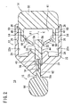
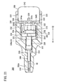
- the direction indicated by the arrow X1 in FIG. 1 points toward a front side (distal end) of the puncture instrument, and the direction indicated by the arrow X2 in FIG. 1 points toward a rear side (proximal end) of the puncture instrument.
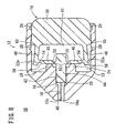
- a puncture instrument 10 As shown in FIGS. 1 to 9 , a puncture instrument 10 according to a first embodiment of the present invention comprises a case 12, a movable member 14 movably disposed in the case 12, and a protective cap 15.
- the case 12 serves as a base of the puncture instrument 10 and has a thin body of pentagonal shape including a substantially square rear portion 12a and a tapered front portion 12b.
- the puncture instrument 10 can be made of resin (e.g., polypropylene or polyethylene) or metal except for a needle 40 to be described later.
- the case 12 has a distal end face 12c having a suitable area for abutting against the skin of a patient.
- the front portion 12b has a hub passage 16 and a needle passage 18 which are formed axially therethrough.
- the needle passage 18 has a distal end opening 18a which is open at the distal end face 12c and a rear end communicating with the hub passage 16.
- the needle passage 18 is smaller in diameter than the hub passage 16, with a step 20 being disposed between the needle passage 18 and the hub passage 16.
- the rear portion 12a has an inner cavity 22 formed by walls surrounding in four directions.
- the inner cavity 22 has a front central end communicating with the hub passage 16 and a rear end which is open rearward.
- the rear portion 12a has a front wall defining the front end of the inner cavity 22 and including two fulcrum members 24 slightly projecting rearward from respective portions in the front wall on the opposite sides of the hub passage 16.
- Each of the fulcrum members 24 has a rear end having a semicircular cross-sectional shape in the planar view.
- the lateral walls 22a of the inner cavity 22 each includes a first recess (first engageable portion) 26 formed therein near the open rear end of the inner cavity 22 and a second recess (second engageable portion) 28 formed therein at substantially axially central position.
- the lateral walls 22a have flat smooth surfaces except the first recesses 26 and the second recesses 28.
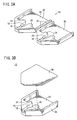
- the case 12 comprises two symmetrical members 30 joined to each other by short bendable members 32.
- the symmetrical members 30 can be brought together about the bendable members 32.
- the case 12 comprises a main body 34 including the hub passage 16, the needle passage 18, and the inner cavity 22, and a lid 36 placed over the main body 34.
- the main body 34 and the lid 36 may be joined to each other by members similar to the bendable members 32 shown in FIG. 3A .
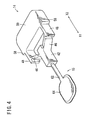
- the movable member 14 comprises a needle assembly 44 including a needle 40 and a hub 42 holding the needle 40, a pair of arms 46 and a pair of push rods 48 which are symmetrically shaped with respect to the longitudinal axis C of the hub 42, and a pusher button (pusher) 50 for pushing the push rods 48 forwardly.
- the movable member 14 has the two arms 46 and the two push rods 48, the arms 46 and the push rods 48 are relatively small in number and simple in structure, and are well-balanced as they are symmetrical in shape.
- the movable member 14 may have a single arm 46 and a single push rod 48 or three or more arms 46 and three or more push rods 48. If the movable member 14 has three or more arms 46 and three or more push rods 48, then the arms 46 and the push rods 48 may be angularly equally spaced from each other around the longitudinal axis C of the hub 42.
- the needle 40 comprises a hollow needle or a solid needle which is made of a metal such as stainless steel, aluminum, or titanium or a hard resin such as polyphenylene sulfide.
- the push rods 48 have a sufficient mechanical strength for pushing the arms 46 and the needle assembly 44 and are elastic enough to be bendable outwardly.
- the push rods 48 thus have a function as leaf springs.
- the needle 40 serves to puncture the skin of a patient and is disposed in a front portion of the needle assembly 44. In the initial state as shown in FIG. 2 , the needle 40 has its tip inserted in the needle passage 18.
- Each of the arms 46 includes a first junction 52 at one end connected to the hub 42 and a second junction 54 at the other end connected to the distal end of the push rod 48.
- the arms 46 are spread outwardly in the rearward direction, and are inclined rearward in respective directions away from the longitudinal axis C of the hub 42.
- the arms 46 are inclined to the longitudinal axis C of the hub 42 at an angle ⁇ 1 of about 50°, for example.
- the arms 46 have respective recesses 56 formed in rear surfaces thereof at the first junctions 52, and respective recesses 58 formed in front surfaces thereof at the second junctions 54. Therefore, the first junctions 52 and the second junctions 54 are narrower than the rest of the arms 46.
- the distal ends of the push rods 48 are joined to the respective arms 46.
- the push rods 48 extend rearward substantially parallel to the longitudinal axis C of the hub 42, and have respective rear ends joined to a front surface of the pusher button 50.
- the push rods 48 are appropriately spaced from the lateral walls 22a.
- the pusher button 50 essentially closes the rear opening of the inner cavity 22. In the initial state, only a front end portion of the pusher button 50 is inserted in the inner cavity 22.
- the front end portion of the pusher button 50 which is inserted in the inner cavity 22 has a pair of protrusions (engaging portions) 60 on opposite outer sides thereof which engage in the respective first recesses 26 in the initial state.
- the pusher button 50 has a rear end projecting a certain distance from the case 12 and having arcuate corners which allow a human hand to operate the pusher button 50 with ease.
- the distance by which the rear end of the pusher button 50 projects from the case 12 is in the range from 5 to 30 mm, for allowing the human hand to push the pusher button 50 with ease.
- the movable member 14 has a space 61 defined therein which is surrounded by the hub 42, the arms 46, the push rods 48, and the pusher button 50.
- the protective cap 15 comprises a tubular member 62 inserted in the hub passage 16 and the needle passage 18 and covering the needle 40, and a tab 64 connected to the front end of the tubular member 62.
- the tubular member 62 has a tapered rear end fixed to the front end face of the hub 42 by fusion, adhesive bonding, or the like.
- the needle 40 has a needle tip portion sealed in the tubular member 62 by insert molding.
- the hub 42 and the protective cap 15 may be integrally molded.
- the protective cap 15 is irradiated with ⁇ -rays, electron beams, or the like to sterilize the needle 40 in the tubular member 62.
- the tab 64 is twisted to wring the tubular member 62 off the hub 42, and the protective cap 15 is removed from the case 12.
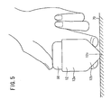
- the case 12 is held by hand to abut the distal end face 12c on the skin 70 of a patient, and the pusher button 50 is pushed into the inner cavity 22.
- the pusher button 50 may be pushed in by the thumb while the front portion 12b is being held between the index finger and the middle finger.
- the case 12 may have some projections as finger stops.
- the movable member 14 When the pusher button 50 is pushed in, the movable member 14 initially does not move because the protrusions 60 engage in the first recesses 26. When stronger force is applied to push the pusher button 50, the protrusions 60 are forced to move out of the first recesses 26. As the pusher button 50 is pushed under the stronger force and the walls 22a have nothing obstructive to the movement of the protrusions 60, the movable member 14 moves quickly forwardly. Accordingly, the movable member 14 ensures a certain puncture speed for the needle 40.
- the tip end of the needle 40 projects from the distal end face 12c of the case 12 and punctures the skin.
- the needle assembly 44 is not biased axially by an elastic body, but is pushed directly by the push rods 48 to cause the needle 40 to puncture the skin stably.
- the distance by which the needle 40 projects from the distal end face 12c is limited when the hub 42 engages the step 20 and is stopped thereby. Therefore, the needle 40 punctures the skin 70 to an appropriate depth.
- the needle assembly 44 stops moving forwardly among the movable member 14. Since the pusher button 50 is continuously pushed in, the arms 46 and the push rods 48 are further displaced forwardly, bringing front surfaces of the arms 46 into abutment with the fulcrum members 24. The fulcrum members 24 engage the front surfaces of the arms 46 near the first junctions 52 on the side opposite to the recesses 56.
- the push rods 48 and the pusher button 50 further move forwardly and then the arms 46 turn about the fulcrum members 24.
- the arms 46 smoothly turn about the fulcrum members 24 because the rear ends of the fulcrum members 24 are semicircular in cross-sectional shape.
- the arms 46 are generally turned about the first junctions 52, causing arc motion of the second junctions 54 about the first junctions 52.
- the distal end of the push rods 48 are pushed outwardly.
- the push rods 48 act as leaf springs and are resiliently bent outwardly about the rear ends of the push rods 48. Since the push rods 48 act as leaf springs, they do not obstruct the turning movement of the arms 46, but allow the arms 46 to move stably.
- the fulcrum members 24 which are positioned closely to the hub 42 are spaced from the hub 42 by certain distances L, respectively (see FIG. 7 ). As the second junctions 54 move forwardly, the first junctions 52 move rearward because the arms 46 are pivoted about the fulcrum members 24. The needle assembly 44 now starts moving rearward.
- the arms 46 are further pivoted about the fulcrum members 24.
- the pusher button 50 reaches the end of its stroke and stops moving when the protrusions 60 engage in the second recesses 28.
- the arms 46 are inclined forwardly in respective directions away from the longitudinal axis C of the hub 42.
- the needle assembly 44 is sufficiently retracted to pull the needle 40 out of the skin 70 into the needle passage 18. Since the arms 46 are turned about the fulcrum members 24 to pull back the needle assembly 44 rearward, the needle 40 is reliably pulled out of the skin 70.
- the arms 46 are inclined to the longitudinal axis C of the hub 42 at an angle ⁇ 2 of about 60°, for example.
- the second junctions 54 are slightly displaced toward the longitudinal axis C of the hub 42, and the push rods 48 are also slightly displaced back toward the longitudinal axis C of the hub 42. Though the resilient force applied from the push rods 48 to the arms 46 is reduced, the force is strong enough to keep the needle assembly 44 pushed rearward.
- first junctions 52 and the second junctions 54 have been plastically deformed and may even have developed some cracking. Therefore, their resilient force has considerably been reduced to the point where the arms 46 can no longer restore their original attitude, i.e., the needle assembly 44 can no longer be pushed back forwardly, so that the arms 46 and the needle assembly 44 remain stably retracted. Since the first junctions 52 and the second junctions 54 are not fully broken, they keep holding the needle assembly 44 within the case 12. The pusher button 50 is prevented from being pulled out to use the puncture instrument 10 again.
- the pusher button 50 is almost entirely or fully inserted in the inner cavity 22 and hence will not subsequently be operated carelessly.
- the pusher button 50 When the pusher button 50 has reached the end of its stroke, it is fully inserted in the inner cavity 22 or its rear end projects out of the inner cavity 22 by a distance of less than 5 mm, so that the pusher button 50 cannot be pulled back out of the inner cavity 22.
- the user can easily recognize whether the puncture instrument 10 is in a state before use or after use, simply by looking at how much the pusher button 50 projects out of the case 12.
- the recesses 56 are formed in the rear surfaces of the arms 46 at the first junctions 52, when the arms 46 are turned about the fulcrum members 24, ends 56a of the recesses 56 move away from the hub 42 and are kept out of interference with the hub 42. Since the recesses 58 are formed in the front surfaces of the arms 46 at the second junctions 54, when the arms 46 are turned about the fulcrum members 24, ends 58a of the recesses 58 move away from the push rods 48 and are kept out of interference with the push rods 48.
- the puncturing action illustrated in FIGS. 2 , 6 , 7 , 8 , and 9 is performed in a very short period of time, so that the tip end of the needle 40 projects instantaneously from the distal end opening 18a of the needle passage 18.
- the skin 70 When the skin 70 is punctured by the needle 40, a small amount of blood flows out of the skin 70 and is sampled. The sampled blood is analyzed by a blood glucose meter or the like, not shown, to measure blood components.
- the puncture instrument 10 is thrown away after use. Since the needle 40 is fully retracted in the needle passage 18, it is free of the danger of being touched by anyone when the puncture instrument 10 is thrown away.
- the puncture instrument 10 offers the following advantages.
- the puncture instrument 10 does not incorporate an elastic body for biasing the needle assembly 44 to move axially. Instead, the needle assembly 44 is pushed outwardly directly by the push rods 48 and the arms 46, causing the needle 40 to puncture the skin 70 stably.
- the puncture instrument 10 does not need a mechanism for compressing an elastic body axially therein and subsequently triggering the resilient member to release its energy to push the needle assembly 44. Therefore, the puncture instrument 10 is relatively simple in structure. After the needle 40 has punctured the skin 70, the arms 46 are turned about the fulcrum members 24 to pull back the needle assembly 44 for thereby reliably pulling the needle 40 from the skin 70.
- the puncture instrument 10 Since the puncture instrument 10 of simple structure can be mass-produced, it is inexpensive and suitable for use as a disposable product.
- the puncture instrument 10 is basically made up of two components, i.e., a composite assembly of the movable member 14 and the protective cap 15, and the case 12. Therefore, puncture instrument 10 is made up of a small number of parts, is simple in structure, and can easily be assembled.
- the pusher button 50 may have recesses instead of the protrusions 60, and the case 12 may have protrusions instead of the first and second recesses 26, 28.
- the case 12 may have an air vent hole for allowing the movable member 14 to move smoothly therein.
- a puncture instrument 100 according to a second embodiment of the present invention will be described below with reference to FIGS. 10 to 12 .
- Those parts of the puncture instrument 100 which are identical to those of the puncture instrument 10 according to the first embodiment are denoted by identical reference characters, and will not be described in detail below.
- the puncture instrument 100 comprises a pusher 102, a balloon (biasing means) 104 for biasing the pusher 102 to be pushed forwardly, a trigger switch (trigger) 106, and a stopper 108 for holding the pusher 102 against forward movement and releasing the pusher 102 to move forwardly when the trigger switch 106 is pressed.
- the pusher 102, the balloon 104, the trigger switch 106, and the stopper 108 are used to perform the function of the pusher button 50 of the puncture instrument 10 according to the first embodiment.
- Other details of the puncture instrument 100 according to the second embodiment are basically the same as those of the puncture instrument 10 according to the first embodiment.
- the case 12 includes a rear end wall 12d covering the rear end of the inner cavity therein.
- the balloon 104 is disposed in a closed space between the pusher 102 and the rear end wall 12d.
- the pusher 102 is constitutively identical to the front end of the pusher button 50 of the puncture instrument 10 according to the first embodiment.
- the two push rods 48 are connected to the pusher 102.
- the rear end wall 12d has a central hole defined therein which holds therein an air supply port 104a of the balloon 104.
- a compressed air supply tube 110 in a hospital can be removably connected to the air supply port 104a.
- the stopper 108 has a rear end connected to the pusher 102 and extends forwardly therefrom.
- the stopper 108 has a front end lightly engaging an end face of a first upper hole 12e formed in the upper wall of the case 12.
- the trigger switch 106 has a rear end connected to the rear end wall 12d of the case 12 and extends forwardly therefrom.
- the trigger switch 106 essentially covers the first upper hole 12e.
- the trigger switch 106 is disposed above and extends along the stopper 108.
- the case 12 also has a second upper hole 12f formed in the upper wall thereof more closely to the distal end than the first upper hole 12e.
- the user of the puncture instrument 100 can confirm through the second upper hole 12f the position of the movable member 14 to see if the puncture instrument 100 is in a state before use or after use.
- the puncture instrument 100 is free of the protrusions 60, the first recesses 26, and the second recesses 28 of the puncture instrument 10 according to the first embodiment.
- the puncture instrument 100 operates as follows: First, the protective cap 15 is removed, and the compressed air supply tube 110 is connected to the air supply port 104a to introduce compressed air into the balloon 104, thereby pressurizing the balloon 104. When the balloon 104 is pressurized, it biases the pusher 102 forwardly. However, the pusher 102 is held at rest because the stopper 108 engages the end face of the first upper hole 12e.
- the user holds the case 12, abuts the distal end face 12c on the skin 70, and then presses the trigger switch 106.
- the trigger switch 106 is resiliently depressed to bring the stopper 108 out of engagement with the end face of the first upper hole 12e.
- the movable member 14 is released and pushed quickly forwardly by the expanding balloon 104, causing the needle 40 to puncture the skin 70.
- the arms 46 are turned about the fulcrum members 24 to pull back the needle 40 from the skin 70 into the needle passage 18.
- the puncture instrument 100 offers the same advantages as those of the puncture instrument 10 according to the first embodiment. Furthermore, the pusher 102 is pushed by the balloon 104, and the trigger switch 106 can be operated with light force.
- the balloon 104 may be replaced with a diaphragm or a bellophragm.
- a packing may be fitted around the pusher 102 and slidably held in contact with the inner wall surface of the case 12, so that the pusher 102 and the case 12 jointly operate as a piston-cylinder mechanism.
- a puncture instrument 200 according to a third embodiment of the present invention will be described below with reference to FIG. 13 .
- Those parts of the puncture instrument 200 which are identical to those of the puncture instruments 10, 100 according to the first and second embodiments are denoted by identical reference characters, and will not be described in detail below.
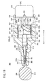
- the puncture instrument 200 comprises a pusher 202, a main magnet (biasing means) 204 disposed in the pusher 202, and a pair of auxiliary magnets (biasing means) 206 disposed symmetrically in the front portion 12b of the case 12.
- the two push rods 48 are connected to the pusher 202 as with the pusher button 50 of the puncture instrument 10.
- the puncture instrument 200 includes the trigger switch 106, the stopper 108, the rear end wall 12d, the first upper hole 12e, and the second upper hole 12f as with the puncture instrument 100.
- the main magnet 204 and the auxiliary magnets 206 are oriented such that their N and S poles face each other to magnetically attract each other for thereby biasing the pusher 202 to be pushed forwardly.
- the puncture instrument 200 operates as follows: The pusher 202 is normally biased to move forwardly under magnetic forces from the main magnet 204 and the auxiliary magnets 206. However, the pusher 202 is held at rest because the stopper 108 engages the end face of the first upper hole 12e. When the user holds the case 12, abuts the distal end face 12c on the skin 70, and then presses the trigger switch 106, the stopper 108 is released out of engagement with the end face of the first upper hole 12e, and the movable member 14 is released and pushed forwardly, causing the needle 40 to puncture the skin 70. Thereafter, the arms 46 are turned about the fulcrum members 24 to pull back the needle 40 from the skin 70 into the needle passage 18.
- the puncture instrument 200 offers the same advantages as those of the puncture instrument 100 according to the second embodiment. Furthermore, the puncture instrument 200 does not require an external power source such as a compressed air source because the pusher 202 is normally biased forwardly under magnetic force from the main magnet 204 and the auxiliary magnets 206.
- the case 12 of the puncture instrument 200 may have holes for removing therethrough the auxiliary magnets 206 and the main magnet 204 after it has reached the end of its stroke.
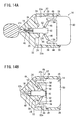
- the first junctions 52 of the arms 46 are rotatably supported on the hub 42.
- the second junctions 54 are plastically deformed as shown in FIG. 14B .
- the second junctions 54 may be rotatably supported on the push rods 48, and the first junctions 52 may be plastically deformed.
- the movable member 14 is stably held at the end of its stroke.
- the first junctions 52 of the arms 46 are rotatably supported on the hub 42, and the second junctions 54 are rotatably supported on the push rods 48.
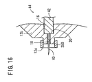
- FIG. 16 shows another modified puncture instrument in which the distal end face 12c is provided by a nut 250 threaded over the distal end of the front portion 12b.
- the distance between the distal end face 12c and the step 20 is changed to adjust the distance by which the needle 40 projects from the distal end face 12c.
- the nut 250 may have an indexing mechanism for setting itself to several angular positions about its own axis. Any of various other mechanisms may be employed to adjust the distance by which the needle 40 projects from the distal end face 12c.
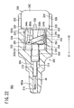
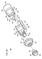
- a puncture instrument 300 according to a fourth embodiment of the present invention will be described below with reference to FIGS. 17 to 22 .
- Those parts of the puncture instrument 300 which are identical to those of the puncture instruments 10, 100, 200 according to the first, second, and third embodiments are denoted by identical reference characters, and will not be described in detail below.
- the puncture instrument 300 comprises a body 302, a hub holder 304 displaceably disposed in the body 302, a hub 306 held on an end of the hub holder 304 and supporting a needle 40, a pusher 308 for pushing the hub holder 304 forwardly, a link mechanism 310 for transferring pressing force applied to the pusher 308 to the hub holder 304, and a protective cap 312 mounted on the body 302.
- the body 302 is of a hollow, substantially cylindrical structure and has a tapered front end portion 302a in which the needle 40 is inserted and a rear end portion 302b that is greater in diameter than the front end portion 302a.
- the pusher 308 is partly exposed from the rear end portion 302b.
- the body 302 has a hub passage 314 and a needle passage 316 formed in the front end portion 302a and extending axially therethrough.
- the needle passage 316 has an end that is open at the front end portion 302a of the body 302 and an opposite end communicating with the hub passage 314.
- the needle passage 316 is smaller in diameter than the hub passage 314, with a first step 318 being disposed between the needle passage 316 and the hub passage 314.
- the rear end portion 302b of the body 302 has an inner cavity 320 formed therein, and the pusher 308 is inserted in the inner cavity 320.
- the inner cavity 320 communicates with the hub passage 314 through a holder hole 322 that is formed centrally in the body 302.
- the inner cavity 320 is of a circular cross-sectional shape and is open at the rear end portion 302b.
- the holder hole 322 is of a substantially rectangular cross-sectional shape, and the hub holder 304 is displaceably disposed in the holder hole 322.
- a second step 324 is provided between the holder hole 322 and the hub passage 314.
- the rear end portion 302b of the body 302 has a plurality of guide grooves 326 formed therein at circumferentially equally spaced angular intervals.
- the pusher 308 has a plurality of protrusions 328, to be described later, inserted respectively in the guide grooves 326.
- the guide grooves 326 have a predetermined length in the axial directions, indicated by the arrows X1, X2, of the body 302.
- the inner cavity 320 of the body 302 communicates with the exterior of the body 302 through the guide grooves 326.
- a pair of fulcrum members 330a, 330b is disposed on the inner wall surface of the holder hole 322 in alignment with the axis of the body 302.
- the fulcrum members 330a, 330b extend a predetermined distance rearward from the inner wall on the hub passage 314 side and have ends of a semicircular cross-sectional shape.
- the fulcrum members 330a, 330b are disposed in confronting relation to each other across the hub holder 304 that is disposed in the holder hole 322.
- a pair of guide slots 332 is formed in another inner wall surface of holder hole 322 at respective positions that are angularly spaced from the fulcrum members 330a, 330b by 90°.
- the guide slots 332 extend axially of the body 302.
- the hub holder 304 comprises a base 334 having a substantially rectangular shape and a hollow cylindrical hub support 336 projecting axially forwardly from the base 334.
- the base 334 has guide rails 338 disposed on respective opposite side surfaces thereof and projecting transversely therefrom.
- the guide rails 338 slidably engage respectively in the guide slots 332 for guiding the hub holder 304 axially in the directions indicated by arrows X1, X2 without allowing the hub holder 304 to rotate about its own axis in the body 302.
- the base 334 has a pair of arm holes 340 formed therethrough at respective positions that are transversely spaced a predetermined distance from each other across the axis of the base 334.
- the link mechanism 310 includes two arms 350a, 350b disposed respectively on upper and lower surfaces of the base 334 and having respectively ends pivotally supported in the arm holes 340, as described later.
- the hub support 336 projects from the front end of the base 334.
- the hub 306 has a rear end fitted in the front end of the hub support 336, and hence is supported by the hub support 336.
- the pusher 308 comprises a cylindrical button 342 and a pair of push rods 344a, 344b projecting from the front end of the button 342.
- the button 342 is partly housed in the inner cavity 320 of the body 302.
- a plurality of protrusions 328 are disposed on an outer circumferential surface of the button 342 and inserted respectively in the guide grooves 326 of the body 302. Since the guide grooves 326 extend in the axial direction of the body 302, the pusher 308 is guided displaceably in the axial directions indicated by the arrows X1, X2.
- the push rods 344a, 344b are offset with respect to the center of the button 342 and project axially linearly a predetermined distance from the button 342. Specifically, as shown in FIG. 18 , the push rods 344a, 344b are vertically spaced from each other across the center of the button 342 by a predetermined distance in the directions indicated by the arrow A and are also horizontally spaced from each other across the center of the button 342 by a predetermined distance in the directions indicated by the arrow B.
- the push rods 344a, 344b have respective wider supports 346 on their distal ends.
- the other ends of the arms 350a, 350b are pivotally supported on the respective supports 346.
- the supports 346 have respective link holes 348 formed therein perpendicularly to the push rods 344a, 344b and extending vertically through the supports 346 parallel to each other, as shown in FIG. 18 .
- the arms 350a, 350b of the link mechanism 310 have respective first pins 352 on ends thereof and respective second pins 354 on the other ends thereof.
- the first and second pins 352, 354 project perpendicularly to the axes of the arms 350a, 350b.
- the first pins 352 project in one direction, and the second pins 354 project in the opposite direction.
- the first pins 352 are inserted respectively in the arm holes 340 of the hub holder 304, and the second pins 354 are inserted respectively in the link holes 348 of the push rods 344a, 344b.
- the first pins 352 function as a first junction connected to the hub holder 304, and the second pins 354 as a second junction connected to the push rods 344a, 344b.
- the arms 350a, 350b are disposed one on each side of the hub holder 304 in mutually crossing relation to each other as shown in FIG. 19 .
- the protective cap 312 comprises a tubular member 356 inserted in the needle passage 316 and covering the needle 40, and a tab 358 connected to the front end of the tubular member 356.
- the tubular member 356 is inserted and fitted in the needle passage 316.
- the tubular member 356 may be fixed to the needle passage 316 by fusion, adhesive bonding, or the like.
- the protective cap 312 is irradiated with ⁇ -rays, electron beams, or the like to sterilize the needle 40 in the tubular member 356.
- the puncture instrument 300 operates as follows: In the state ready for puncture as shown in FIG. 19 , the tab 358 of the protective cap 312 is twisted to release the tubular member 356 out of fitting engagement with the body 302, thereby removing the protective cap 312.
- the body 302 is held by hand to abut the front end portion 302a on the skin (not shown), and the button 342 of the pusher 308 is pushed toward the body 302 in the direction indicated by the arrow X1.
- the button 342 may be pushed in by the thumb while the region of the body 302 near the front end portion 302a is being held between the index finger and the middle finger.
- the pusher 308 When the pusher 308 is pushed, since the protrusions 328 engage the inner wall surface of the inner cavity 320, the pusher 308 is initially limited somewhat in its displacement. As the pushing forces applied to the pusher 308 are increased, the protrusions 328 are displaced out of engagement with the inner wall surface of the inner cavity 320 and inserted into the guide grooves 326 (see FIG. 20 ). The pusher 308 is now guided to move in the axial direction of the body 302 toward the front end portion 302a of the body 302 in the direction indicated by the arrow X1.
- the arms 350a, 350b pivotally supported by the push rods 344a, 344b and the hub holder 304 are displaced toward the front end portion 302a, displacing the hub 306 held by the hub holder 304 along the hub passage 314 and the needle passage 316.
- the arms 350a, 350b do not turn, but are displaced in unison with the pusher 308 and the hub holder 304. Stated otherwise, the arms 350a, 350b are kept as struts between the hub holder 304 and the pusher 308.
- the hub holder 304 is displaced only axially without being rotated about its own axis because it is guided by the guide rails 338 engaging in the respective guide slots 332.
- the tip end of the needle 40 projects from the front end portion 302a of the body 302 and punctures the skin.
- the needle 40 is not biased axially by an elastic body, but is pushed directly by the push rods 344a, 344b and the hub holder 304 as the pusher 308 is pushed.
- the axial displacement of the needle 40 is limited when the hub 306 engages the first step 318, so that the distance by which the needle 40 projects from the front end portion 302a of the body 302 is controlled. Therefore, the needle 40 punctures the skin to an appropriate depth.
- the arms 350a, 350b gradually turn about the second pins 354 by the push rods 344a, 344b.
- the turn of the arms 350a, 350b pulls the hub holder 304 toward the pusher 308 in the direction indicated by the arrow X2, because the arms 350a, 350b have their substantially central regions abutting against the ends of the fulcrum members 330a, 330b, and turn about the abutting regions from the initial angular position of the arms 350a, 350b with respect to the hub holder 304 and the pusher 308.
- the hub 306 held by the hub holder 304 is displaced in a direction into the body 302, retracting the needle 40 into the needle passage 316.
- the body 302 of the puncture instrument 300 is of a hollow cylindrical shape. Before the puncture instrument 300 is in use, the front end portion 302a of the body 302 with the protective cap 312 mounted thereon is highly sealed. Specifically, the needle passage 316 in which the needle 40 is housed is highly hermetically sealed to keep the needle 40 sterilized after the needle 40 has been sterilized.
- the hub 306 and the hub holder 304 are separate from each other.
- the hub 306 and the hub holder 304 may be integrally combined with each other.
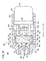
- a puncture instrument 400 according to a fifth embodiment of the present invention will be described below with reference to FIGS. 23 to 28 .
- Those parts of the puncture instrument 400 which are identical to those of the puncture instruments 10, 100, 200, 400 according to the first, second, third, and fourth embodiments are denoted by identical reference characters, and will not be described in detail below.
- the puncture instrument 400 comprises a body 402, a movable member (pusher) 404 displaceably disposed in the body 402, an adjustment dial 406 for adjusting the depth to which the needle 40 on the movable member 404 punctures the skin, and a protective cap 408 mounted on the front end of the body 402.
- the body 402 is of a hollow, substantially cylindrical structure and has a small-diameter portion 410 on its front end in which the needle 40 is inserted and a large-diameter portion 412 on its rear end that is greater in diameter than the small-diameter portion 410.
- the movable member 404 is partly exposed from the rear end of the body 402.
- the small-diameter portion 410 and the large-diameter portion 412 are substantially constant in diameter.
- the small-diameter portion 410 has an externally threaded outer circumferential surface 414.
- the body 402 has a needle passage 416 formed axially centrally through the small-diameter portion 410, and an inner cavity 418 formed in the large-diameter portion 412 with the movable member 404 disposed in the inner cavity 418.
- the body 402 also has a holder hole 420 (hub passage) formed therein axially between the needle passage 416 and the inner cavity 418.
- the movable member 404 has a base 432 held in the holder hole 420.
- the small-diameter portion 410 has a cap hole 422 formed therein at the end of the needle passage 416.
- the protective cap 408 is partly mounted in the cap hole 422.
- the cap hole 422 is open outwardly at the distal end of the small-diameter portion 410 and is larger in diameter than the needle passage 416.
- the large-diameter portion 412 includes an annular ridge 424 disposed on the proximal end of the inner cavity 418 and slightly projecting radially inwardly.
- the movable member 404 has an outer circumferential surface slidably engaging the annular ridge 424.
- the holder hole 420 is of a substantially rectangular cross-sectional shape.
- a pair of fulcrum members 426a, 426b is disposed on the inner wall surface of holder hole 420 in alignment with the axis of the body 402.
- the fulcrum members 426a, 426b extend rearward a predetermined distance from the inner wall surface on the needle passage 416 side and have ends of a semicircular cross-sectional shape.
- a pair of guide slots 428 is formed in the inner wall surface of holder hole 420 at respective positions that are angularly spaced from the fulcrum members 426a, 426b by 90°.
- the guide slots 428 extend in the axial direction of the body 402 in the directions indicated by the arrows X1, X2.
- the movable member 404 comprises a needle assembly 430 including a needle 40 and a hub 429 which holds the needle 40, a base 432 on which the needle assembly 430 is mounted, a pair of arms 434a, 434b integrally joined to the base 432, a pair of push rods 436a, 436b integrally joined to the respective arms 434a, 434b, and a pusher button 438 for pushing the push rods 436a, 436b forwardly.
- the arms 434a, 434b include respective first junctions 440 at one ends joined to the base 432 and respective second junctions 442 at the other ends joined to the distal ends of the push rods 436a, 436b.
- the arms 434a, 434b are inclined at a certain angle to the axis of the movable member 404 and are disposed in a mutually crossing relation to each other with the base 432 therebetween as shown in FIG. 25 .
- the arms 434a, 434b have respective recesses 444 formed in rear surfaces thereof at the first junctions 440, and respective recesses 446 formed in front surfaces thereof at the second junctions 442. Therefore, the first junctions 440 and the second junctions 442 are narrower than the rest of the arms 434a, 434b.
- the push rods 436a, 436b project from the end face of the button 438 and extend in the axial direction of the movable member 404.
- the second junctions 442 of the arms 434a, 434a are connected respectively to the distal ends of the push rods 436a, 436b.
- the button 438 is disposed to close the opening of the inner cavity 418, and has its end projecting from the inner cavity 418 when the puncture instrument 400 is in the state ready for puncture (see FIG. 25 ).
- the other end of button 438 to which the push rods 436a, 436b are connected has an annular ridge 448 on its outer circumferential surface.
- the adjustment dial 406 is of a ring shape and includes an internally threaded inner circumferential surface 450 threaded over the small-diameter portion 410 of the body 402.
- the adjustment dial 406 has graduations 452 on its outer circumferential surface. When the adjustment dial 406 is turned, it is axially moved on the small-diameter portion 410 in the directions indicated by the arrows X1, X2. Since the front end of the adjustment dial 406 can be displaced a predetermined distance toward the distal end with respect to the front end of the body 402, it is possible to adjust the distance by which the needle 40 projects from the front end of the adjustment dial 406.
- the protective cap 408 comprises a tubular member 454 fitted in the cap hole 422 in the body 402 and a grip 456 joined to the tubular member 454 for being gripped when the protective cap 408 is to be removed.
- the tubular member 454 is in the form of a hollow bottomed cylinder and houses a portion of the needle 40 therein when the protective cap 408 is mounted on the body 402. In the state that the protective cap 408 is mounted on the body 402, the puncture instrument 400 is irradiated with ⁇ -rays, electron beams, or the like to sterilize the needle 40 in the tubular member 454.
- the puncture instrument 400 operates as follows: In the state ready for puncture as shown in FIG. 25 , the grip 456 of the protective cap 408 is twisted to release the tubular member 454 out of fitting engagement with the body 402, thereby removing the protective cap 408.
- the body 402 is held by hand to abut the front end portion on the skin (not shown), and the button 438 of the movable member 404 is pushed toward the body 402 in the direction indicated by the arrow X1.
- the annular ridge 448 of the button 438 is out of engagement with the annular ridge 424 of the body 402 and inserted into the inner cavity 418.
- the movable member 404 is now guided toward the front end portion of the body 402 in the axial direction thereof indicated by the arrow X1 (see FIG. 26 ).
- the hub 429 mounted on the base 432 is displaced in and along the needle passage 416 and the cap hole 422.
- the movable member 404 is displaced only axially without being rotated about its own axis because it is guided by the guide rails 338 engaging in the respective guide slots 428.
- the tip end of the needle 40 projects from the front end portion of the body 402 and punctures the skin.
- the needle 40 is not biased axially by an elastic body, but is pushed directly by the push rods 436a, 346b and the arms 434a, 434b as the movable member 404 is pushed.
- the wall surface of the holder hole 420 limits the axial displacement of the needle 40 by abutment against the base 432.
- the substantially central regions of the arms 434a, 434b abut against the fulcrum members 426a, 426b, and the arms 434a, 434b gradually turn about the abutting regions so as to move the first junctions 440 toward the proximal end of the body 402 and the second junctions 442 toward the distal end of the body 402.
- the arms 434a, 434b turn, the base 432 is pulled toward the button 438 in the direction indicated by the arrow X2, displacing the hub 429 held by the base 432 into the body 402 thereby to retract the needle 40 into the needle passage 416 of the body 402.
- the distal ends of the push rods 436a, 436b are elastically bent outwardly away from each other.
- the second junctions 442 of the arms 434a, 434b are pushed in toward the front end portion of the body 402 by the push rods 436a, 436b, and the first junctions 440 of the arms 434a, 434b are pulled toward the button 438 in the direction indicated by the arrow X2, which is opposite to the direction in which the second junctions 442 are pushed, because the arms 434a, 434b are abutted against the fulcrum members 426a, 426b.
- the base 432 is further moved toward the button 438 in the direction indicated by the arrow X2, moving the hub 429 and the needle 40 along the needle passage 416 toward the button 438.
- the button 438 Since the annular ridge 448 of the button 438 is fully inserted in the inner cavity 418, the button 438 will not inadvertently be brought out of the inner cavity 418 beyond the annular ridge 424 after the puncturing process is finished. If a second annular ridge is provided on the inner circumferential surface of the inner cavity 418 near the holder hole 420 for engagement with the annular ridge 448, then the button 438 is prevented more effectively from being brought out of the inner cavity 418.
- the body 402 is of a hollow, substantially cylindrical structure, the front end portion of the body 402 on which the protective cap 408 is mounted and the rear end portion of the body 402 in which the button 438 is fitted are highly sealed before the puncture instrument 400 is used. As a result, the needle 40 remains sterilized after sterilization.
- the arms 434a, 434b are constituted as integral components of the movable member 404, unlike the arms of the puncture instrument 300 according to the fourth embodiment. Therefore, the puncture instrument 400 is made of a reduced number of components and can be assembled with a reduced number of assembling steps.
Abstract
Description
- The present invention relates to a puncture instrument comprising a needle for instantaneously projecting the needle to puncture the human skin therewith.
- Diabetic patients are generally recommended to perform a daily self-management of diabetes by measuring blood sugar levels by themselves. Blood sugar levels can be measured using blood component measuring devices. According to one blood component measuring device, it holds a test paper impregnated with a reagent which produces a color change dependent on the amount of glucose contained in a blood sample that is brought into contact with the test paper. In operation, a blood sample is applied to the test paper, and the degree of a color change produced by the reagent is optically measured to determine the blood sugar level of the blood sample. The determined blood sugar level is then displayed. Another blood component measuring device employs an electrochemical sensor for measuring the blood sugar level of a blood sample.
- In order for a diabetic patient to sample its own blood, the diabetic patient uses a puncture instrument equipped with a puncture needle tip having an axially movable needle. The puncture needle tip, which is removably mounted on the puncture instrument, exerts repulsive force from an elastic body to a needle therein to cause the needle to project instantaneously and puncture the skin, e.g., a finger, a palm, an arm, or the like, of the patient for thereby letting a small amount of blood to flow out. After the puncture, the needle is retracted by a return mechanism.
- Generally, the puncture instrument is used with the puncture needle tip mounted thereon, and the puncture needle tip is thrown away after use. Though hospitals and clinics have a considerably large number of puncture needle tips ready for use depending on the number of patients and the frequency of blood sugar measurements, they have a relatively small number of puncture instruments available. Therefore, if many patients need to be simultaneously measured for blood sugar levels, it may take a longer time to measure blood sugar levels for all the patients than usual because not enough puncture instruments may be available. Since a puncture needle tip has to be mounted on and removed from the puncture instrument for each measurement session, there are demands for simpler puncture instruments.
- Japanese Patent No.
3795511 - Document
WO 2007/024152 discloses a puncture instrument according to the preamble ofclaim 1. - It is an object of the present invention to provide a puncture instrument which can be operated stably and is simple in structure.
- A puncture instrument according to the present invention comprises a case, a needle assembly movably disposed in the case and including a needle and a hub holding the needle, a hub passage for axially guiding the hub, the hub passage being disposed in the case, a needle passage disposed in the case and communicating with the hub passage, the needle passage having a distal end opening for allowing a tip end of the needle to project therethrough, at least one arm having a first junction on an end thereof connected to the hub and a second junction on another end thereof, the arm being inclined from the first junction toward a proximal end of the case in an initial state, a push rod joined to the second junction and extending toward the proximal end, a pusher for pushing the push rod toward a distal end of the case, and a fulcrum member for abutting against a portion of the arm when the arm moves, wherein when the push rod is pushed toward the distal end by the pusher, the arm pushes the needle assembly toward the distal end, brings the portion thereof into abutment against the fulcrum member, and turns about the fulcrum member, so that the arm is inclined from the first junction toward the distal end thereby to pull back the needle assembly toward the proximal end.
- With the above puncture instrument, the needle assembly is pushed directly by the push rod, is not mediated with an elastic body for axially biasing the needle assembly, can puncture a skin stably, and is simple in structure. After the needle has punctured the skin, the arm turns about the fulcrum member to pull back the needle reliably out of the skin. The term "case" referred to above is used in a broad sense and represents a member serving as a base of the puncture instrument.
- The push rod may comprise a leaf spring which is elastically deformable under the force applied from the arm when the push rod is pushed toward the distal end by the pusher. If the push rod comprises a leaf spring, then it does not obstruct the turning of the arm and allows the arm to operate more stably. When the needle assembly has finished its movement, the needle assembly is resiliently biased to move rearward under the resilient force of the push rod.
- The arm may be inclined toward the proximal end in a direction away from the hub in the initial state, and when the push rod is pushed toward the distal end as the pusher is pushed, the arm may turn about the fulcrum member and incline toward the distal end in a direction away from the hub.
- At least one of the first junction and the second junction may be narrower than the arm and may be plastically deformable when the arm turns and changes its inclination direction. If at least one of the first junction and the second junction is plastically deformable, then the pusher is stably kept in a stroke end position and does not move back to the initial state. Thus, the puncture instrument is prevented from being reused.
- The hub may include a base on a proximal end portion thereof and having a flat surface parallel to a plane in which the arm turns, the first junction being rotatably connected to the base at a position on the plane which is spaced a predetermined distance from a longitudinal axis of the hub.
- The pusher may include a convex or concave engaging portion, and the case may include a first engageable portion for engaging the engaging portion when the pusher is in an initial position, and a second engageable portion for engaging the engaging portion when the pusher is in a stroke end position.
- In the initial position, the pusher has its engaging portion engaging the first engageable portion and will not move accidentally. When the pusher is strongly pushed toward the distal end, the engaging portion disengages from the first engageable portion, allowing the pusher and the needle assembly to move forcefully toward the distal end. The needle can thus puncture the skin at a certain speed. Thereafter, the engaging portion engages the second engageable portion, holding the pusher stably in position.
- The pusher may be movably disposed in an inner cavity formed in the case and have a proximal end projecting from the case by a distance ranging from 5 to 30 mm when the pusher is in an initial position, and projecting from the case by a distance of less than 5 mm when the pusher is in a stroke end position. With this arrangement, the user of the puncture instrument can easily recognize whether the puncture instrument has been used or not by confirming the position of the pusher projecting from the case. After the puncture instrument has been used, the pusher is inserted almost entirely in the case and prevented from being accidentally pulled back out of the case.
- The needle passage may be narrower than the hub passage, and a step is provided between the needle passage and the hub passage, for abutting a distal end surface of the hub on the step to limit the needle assembly against movement. The step is reliably effective to limit the needle assembly against movement, thereby achieving an appropriate depth to which the needle punctures the skin.
- The arm may comprise two arms and the push rod may comprise two push rods, the two arms and the two push rods being symmetrical about a longitudinal axis of the hub. The two arms and the two push rods provide a relatively simple structure with few components, are symmetrical in structure, and are well balanced.
- The puncture instrument may further comprise biasing means for biasing the pusher to be pushed toward the distal end, and a stopper for limiting the pusher biased by the biasing means against movement toward the distal end and releasing the pusher in response to operation of a trigger. The biasing means allows the user to operate the trigger with light force to cause the needle to puncture the skin.
- The case may be of a hollow cylindrical shape, and the puncture instrument may further comprise a protective cap removably mounted on a distal end of the case for holding and sealing the needle in the needle passage. The hollow cylindrical case can highly be sealed when the protective cap is mounted thereon, thereby keeping the needle sterilized.
- The puncture instrument according to the present invention offers the following advantages.
- The needle assembly is pushed directly by the push rod, is not mediated with an elastic member for axially biasing the needle assembly, can puncture a skin stably, and is simple in structure. After the needle has punctured the skin, the arm turns about the fulcrum member to pull back the needle reliably out of the skin.
- Further, the lancet assembly disclosed in Japanese Patent No.
3795511 - The above and other objects, features, and advantages of the present invention will become more apparent from the following description when taken in conjunction with the accompanying drawings in which preferred embodiments of the present invention are shown by way of illustrative example.
-
-
FIG. 1 is an external perspective view of a puncture instrument according to a first embodiment of the present invention; -
FIG. 2 is a cross-sectional view of the puncture instrument shown inFIG. 1 , showing an initial state thereof; -
FIG. 3A is a perspective view of a case according to a first example as it is spread out; -
FIG. 3B is a perspective view of a case according to a second example; -
FIG. 4 is a perspective view of a movable member of the puncture instrument; -
FIG. 5 is a schematic view showing the manner in which the puncture instrument is abutted on the skin; -
FIG. 6 is a cross-sectional view of the puncture instrument with a hub abutted against a step; -
FIG. 7 is a cross-sectional view of the puncture instrument with arms abutted against fulcrum members; -
FIG. 8 is a cross-sectional view of the puncture instrument with the arms being turned about the fulcrum members; -
FIG. 9 is a cross-sectional view of the puncture instrument at the time the movable member has reached the end of its stroke; -
FIG. 10 is a perspective view of a puncture instrument according to a second embodiment of the present invention; -
FIG. 11 is a cross-sectional view of the puncture instrument shown inFIG. 10 , showing an initial state thereof; -
FIG. 12 is a sectional side view of the puncture instrument shown inFIG. 11 ; -
FIG. 13 is a perspective view of a puncture instrument according to a third embodiment of the present invention, showing an initial state thereof; -
FIG. 14A is a cross-sectional view showing arms according to a first modification in an initial state thereof; -
FIG. 14B is a cross-sectional view showing the arms according to the first modification at the time the movable member has reached the end of its stroke; -
FIG. 15 is a cross-sectional view showing arms according to a second modification; -
FIG. 16 is an enlarged cross-sectional view of a distal end portion of a modified puncture instrument which is combined with a nut for adjusting the projection of a needle; -
FIG. 17 is a perspective view of a puncture instrument according to a fourth embodiment of the present invention; -
FIG. 18 is an exploded perspective view, partly shown in cross section, of the puncture instrument shown inFIG. 17 ; -
FIG. 19 is a cross-sectional view of the puncture instrument shown inFIG. 17 , showing the puncture instrument in a state ready for puncture; -
FIG. 20 is a cross-sectional view of the puncture instrument shown inFIG. 17 , showing the manner in which after a protective cap is removed from the puncture instrument a needle punctures the skin of a patient; -
FIG. 21 is a cross-sectional view of the puncture instrument shown inFIG. 17 with arms abutted against fulcrum members and turning; -
FIG. 22 is a cross-sectional view of the puncture instrument shown inFIG. 17 at the time a pusher has reached the end of its stroke; -
FIG. 23 is a perspective view of a puncture instrument according to a fifth embodiment of the present invention; -
FIG. 24 is an exploded perspective view, partly shown in cross section, of the puncture instrument shown inFIG. 23 ; -
FIG. 25 is a cross-sectional view of the puncture instrument shown inFIG. 23 , showing the puncture instrument in a state ready for puncture; -
FIG. 26 is a cross-sectional view of the puncture instrument shown inFIG. 23 , showing the manner in which after a protective cap is removed from the puncture instrument a needle punctures the skin; -
FIG. 27 is a cross-sectional view of the puncture instrument shown inFIG. 23 with arms abutted against fulcrum members and turning; and -
FIG. 28 is a cross-sectional view of the puncture instrument shown inFIG. 23 at the time a movable member has reached the end of its stroke. - Puncture devices according to preferred embodiments of the present invention will be described below with reference to
FIGS. 1 to 28 of the accompanying drawings. The direction indicated by the arrow X1 inFIG. 1 points toward a front side (distal end) of the puncture instrument, and the direction indicated by the arrow X2 inFIG. 1 points toward a rear side (proximal end) of the puncture instrument. - As shown in
FIGS. 1 to 9 , apuncture instrument 10 according to a first embodiment of the present invention comprises acase 12, amovable member 14 movably disposed in thecase 12, and aprotective cap 15. Thecase 12 serves as a base of thepuncture instrument 10 and has a thin body of pentagonal shape including a substantially squarerear portion 12a and a taperedfront portion 12b. Thepuncture instrument 10 can be made of resin (e.g., polypropylene or polyethylene) or metal except for aneedle 40 to be described later. Thecase 12 has adistal end face 12c having a suitable area for abutting against the skin of a patient. - As shown in
FIG. 2 , thefront portion 12b has ahub passage 16 and aneedle passage 18 which are formed axially therethrough. Theneedle passage 18 has adistal end opening 18a which is open at thedistal end face 12c and a rear end communicating with thehub passage 16. Theneedle passage 18 is smaller in diameter than thehub passage 16, with astep 20 being disposed between theneedle passage 18 and thehub passage 16. - The
rear portion 12a has aninner cavity 22 formed by walls surrounding in four directions. Theinner cavity 22 has a front central end communicating with thehub passage 16 and a rear end which is open rearward. Therear portion 12a has a front wall defining the front end of theinner cavity 22 and including twofulcrum members 24 slightly projecting rearward from respective portions in the front wall on the opposite sides of thehub passage 16. Each of thefulcrum members 24 has a rear end having a semicircular cross-sectional shape in the planar view. - The
lateral walls 22a of theinner cavity 22 each includes a first recess (first engageable portion) 26 formed therein near the open rear end of theinner cavity 22 and a second recess (second engageable portion) 28 formed therein at substantially axially central position. Thelateral walls 22a have flat smooth surfaces except thefirst recesses 26 and the second recesses 28. - As shown in
FIG. 3A , according to a first example, thecase 12 comprises twosymmetrical members 30 joined to each other by shortbendable members 32. Thesymmetrical members 30 can be brought together about thebendable members 32. As shown inFIG. 3B , according to a second example, thecase 12 comprises amain body 34 including thehub passage 16, theneedle passage 18, and theinner cavity 22, and alid 36 placed over themain body 34. Themain body 34 and thelid 36 may be joined to each other by members similar to thebendable members 32 shown inFIG. 3A . - As shown in
FIGS. 2 and4 , themovable member 14 comprises aneedle assembly 44 including aneedle 40 and ahub 42 holding theneedle 40, a pair ofarms 46 and a pair ofpush rods 48 which are symmetrically shaped with respect to the longitudinal axis C of thehub 42, and a pusher button (pusher) 50 for pushing thepush rods 48 forwardly. Since themovable member 14 has the twoarms 46 and the twopush rods 48, thearms 46 and thepush rods 48 are relatively small in number and simple in structure, and are well-balanced as they are symmetrical in shape. However, themovable member 14 may have asingle arm 46 and asingle push rod 48 or three ormore arms 46 and three ormore push rods 48. If themovable member 14 has three ormore arms 46 and three ormore push rods 48, then thearms 46 and thepush rods 48 may be angularly equally spaced from each other around the longitudinal axis C of thehub 42. - The
needle 40 comprises a hollow needle or a solid needle which is made of a metal such as stainless steel, aluminum, or titanium or a hard resin such as polyphenylene sulfide. Thepush rods 48 have a sufficient mechanical strength for pushing thearms 46 and theneedle assembly 44 and are elastic enough to be bendable outwardly. Thepush rods 48 thus have a function as leaf springs. When thepush rods 48 are in an initial state shown inFIG. 2 , i.e., in storage prior to use, thepush rods 48 are free of elastic strains and their resilient force will not be reduced even when thepush rods 48 are kept in storage over a long period of time. - The
needle 40 serves to puncture the skin of a patient and is disposed in a front portion of theneedle assembly 44. In the initial state as shown inFIG. 2 , theneedle 40 has its tip inserted in theneedle passage 18. - Each of the
arms 46 includes afirst junction 52 at one end connected to thehub 42 and asecond junction 54 at the other end connected to the distal end of thepush rod 48. In the initial state, thearms 46 are spread outwardly in the rearward direction, and are inclined rearward in respective directions away from the longitudinal axis C of thehub 42. Thearms 46 are inclined to the longitudinal axis C of thehub 42 at an angle θ1 of about 50°, for example. - The
arms 46 haverespective recesses 56 formed in rear surfaces thereof at thefirst junctions 52, andrespective recesses 58 formed in front surfaces thereof at thesecond junctions 54. Therefore, thefirst junctions 52 and thesecond junctions 54 are narrower than the rest of thearms 46. - The distal ends of the
push rods 48 are joined to therespective arms 46. Thepush rods 48 extend rearward substantially parallel to the longitudinal axis C of thehub 42, and have respective rear ends joined to a front surface of thepusher button 50. Thepush rods 48 are appropriately spaced from thelateral walls 22a. - The
pusher button 50 essentially closes the rear opening of theinner cavity 22. In the initial state, only a front end portion of thepusher button 50 is inserted in theinner cavity 22. The front end portion of thepusher button 50 which is inserted in theinner cavity 22 has a pair of protrusions (engaging portions) 60 on opposite outer sides thereof which engage in the respectivefirst recesses 26 in the initial state. Thepusher button 50 has a rear end projecting a certain distance from thecase 12 and having arcuate corners which allow a human hand to operate thepusher button 50 with ease. The distance by which the rear end of thepusher button 50 projects from thecase 12 is in the range from 5 to 30 mm, for allowing the human hand to push thepusher button 50 with ease. - The
movable member 14 has aspace 61 defined therein which is surrounded by thehub 42, thearms 46, thepush rods 48, and thepusher button 50. - The
protective cap 15 comprises atubular member 62 inserted in thehub passage 16 and theneedle passage 18 and covering theneedle 40, and atab 64 connected to the front end of thetubular member 62. Thetubular member 62 has a tapered rear end fixed to the front end face of thehub 42 by fusion, adhesive bonding, or the like. Theneedle 40 has a needle tip portion sealed in thetubular member 62 by insert molding. Thehub 42 and theprotective cap 15 may be integrally molded. Theprotective cap 15 is irradiated with γ-rays, electron beams, or the like to sterilize theneedle 40 in thetubular member 62. - Operation of the
puncture instrument 10 thus constituted will be described below. - First, the
tab 64 is twisted to wring thetubular member 62 off thehub 42, and theprotective cap 15 is removed from thecase 12. - Then, as shown in
FIG. 5 , thecase 12 is held by hand to abut thedistal end face 12c on theskin 70 of a patient, and thepusher button 50 is pushed into theinner cavity 22. At this time, thepusher button 50 may be pushed in by the thumb while thefront portion 12b is being held between the index finger and the middle finger. Thecase 12 may have some projections as finger stops. - When the
pusher button 50 is pushed in, themovable member 14 initially does not move because theprotrusions 60 engage in the first recesses 26. When stronger force is applied to push thepusher button 50, theprotrusions 60 are forced to move out of the first recesses 26. As thepusher button 50 is pushed under the stronger force and thewalls 22a have nothing obstructive to the movement of theprotrusions 60, themovable member 14 moves quickly forwardly. Accordingly, themovable member 14 ensures a certain puncture speed for theneedle 40. - As shown in
FIG. 6 , when themovable member 14 moves forwardly, the tip end of theneedle 40 projects from thedistal end face 12c of thecase 12 and punctures the skin. Specifically, theneedle assembly 44 is not biased axially by an elastic body, but is pushed directly by thepush rods 48 to cause theneedle 40 to puncture the skin stably. The distance by which theneedle 40 projects from thedistal end face 12c is limited when thehub 42 engages thestep 20 and is stopped thereby. Therefore, theneedle 40 punctures theskin 70 to an appropriate depth. - As shown in
FIG. 7 , when thehub 42 engages thestep 20, theneedle assembly 44 stops moving forwardly among themovable member 14. Since thepusher button 50 is continuously pushed in, thearms 46 and thepush rods 48 are further displaced forwardly, bringing front surfaces of thearms 46 into abutment with thefulcrum members 24. Thefulcrum members 24 engage the front surfaces of thearms 46 near thefirst junctions 52 on the side opposite to therecesses 56. - As shown in
FIG. 8 , as thepusher button 50 is further pushed in, thepush rods 48 and thepusher button 50 further move forwardly and then thearms 46 turn about thefulcrum members 24. At this time, thearms 46 smoothly turn about thefulcrum members 24 because the rear ends of thefulcrum members 24 are semicircular in cross-sectional shape. - Inasmuch as the
fulcrum members 24 engage thearms 46 near thehub 42, thearms 46 are generally turned about thefirst junctions 52, causing arc motion of thesecond junctions 54 about thefirst junctions 52. The distal end of thepush rods 48 are pushed outwardly. At this time, thepush rods 48 act as leaf springs and are resiliently bent outwardly about the rear ends of thepush rods 48. Since thepush rods 48 act as leaf springs, they do not obstruct the turning movement of thearms 46, but allow thearms 46 to move stably. - When the
arms 46 turn, stresses concentrate on thefirst junctions 52 and thesecond junctions 54 which are narrow so that thefirst junctions 52 and thesecond junctions 54 are plastically deformed beyond the elastic range. - The
fulcrum members 24 which are positioned closely to thehub 42 are spaced from thehub 42 by certain distances L, respectively (seeFIG. 7 ). As thesecond junctions 54 move forwardly, thefirst junctions 52 move rearward because thearms 46 are pivoted about thefulcrum members 24. Theneedle assembly 44 now starts moving rearward. - As shown in
FIG. 9 , upon further forward movement of thepush rods 48 and thepusher button 50 among themovable member 14, thearms 46 are further pivoted about thefulcrum members 24. Thepusher button 50 reaches the end of its stroke and stops moving when theprotrusions 60 engage in the second recesses 28. - At this time, the
arms 46 are inclined forwardly in respective directions away from the longitudinal axis C of thehub 42. Theneedle assembly 44 is sufficiently retracted to pull theneedle 40 out of theskin 70 into theneedle passage 18. Since thearms 46 are turned about thefulcrum members 24 to pull back theneedle assembly 44 rearward, theneedle 40 is reliably pulled out of theskin 70. Thearms 46 are inclined to the longitudinal axis C of thehub 42 at an angle θ2 of about 60°, for example. When theneedle assembly 44 is fully retracted, thehub 42 enters thespace 61 sufficient to both thehub 42 and thepusher button 50. Therefore, theneedle assembly 44 does not interfere with thepusher button 50. - As the
arms 46 are turned about thefulcrum members 24, thesecond junctions 54 are slightly displaced toward the longitudinal axis C of thehub 42, and thepush rods 48 are also slightly displaced back toward the longitudinal axis C of thehub 42. Though the resilient force applied from thepush rods 48 to thearms 46 is reduced, the force is strong enough to keep theneedle assembly 44 pushed rearward. - At this time, the
first junctions 52 and thesecond junctions 54 have been plastically deformed and may even have developed some cracking. Therefore, their resilient force has considerably been reduced to the point where thearms 46 can no longer restore their original attitude, i.e., theneedle assembly 44 can no longer be pushed back forwardly, so that thearms 46 and theneedle assembly 44 remain stably retracted. Since thefirst junctions 52 and thesecond junctions 54 are not fully broken, they keep holding theneedle assembly 44 within thecase 12. Thepusher button 50 is prevented from being pulled out to use thepuncture instrument 10 again. - The
pusher button 50 is almost entirely or fully inserted in theinner cavity 22 and hence will not subsequently be operated carelessly. When thepusher button 50 has reached the end of its stroke, it is fully inserted in theinner cavity 22 or its rear end projects out of theinner cavity 22 by a distance of less than 5 mm, so that thepusher button 50 cannot be pulled back out of theinner cavity 22. The user can easily recognize whether thepuncture instrument 10 is in a state before use or after use, simply by looking at how much thepusher button 50 projects out of thecase 12. - Since the
recesses 56 are formed in the rear surfaces of thearms 46 at thefirst junctions 52, when thearms 46 are turned about thefulcrum members 24, ends 56a of therecesses 56 move away from thehub 42 and are kept out of interference with thehub 42. Since therecesses 58 are formed in the front surfaces of thearms 46 at thesecond junctions 54, when thearms 46 are turned about thefulcrum members 24, ends 58a of therecesses 58 move away from thepush rods 48 and are kept out of interference with thepush rods 48. - The puncturing action illustrated in
FIGS. 2 ,6 ,7 ,8 , and9 is performed in a very short period of time, so that the tip end of theneedle 40 projects instantaneously from the distal end opening 18a of theneedle passage 18. - When the
skin 70 is punctured by theneedle 40, a small amount of blood flows out of theskin 70 and is sampled. The sampled blood is analyzed by a blood glucose meter or the like, not shown, to measure blood components. Thepuncture instrument 10 is thrown away after use. Since theneedle 40 is fully retracted in theneedle passage 18, it is free of the danger of being touched by anyone when thepuncture instrument 10 is thrown away. - The
puncture instrument 10 according to the first embodiment offers the following advantages. Thepuncture instrument 10 does not incorporate an elastic body for biasing theneedle assembly 44 to move axially. Instead, theneedle assembly 44 is pushed outwardly directly by thepush rods 48 and thearms 46, causing theneedle 40 to puncture theskin 70 stably. As theneedle assembly 44 is pushed outwardly directly by thepush rods 48 and thearms 46, thepuncture instrument 10 does not need a mechanism for compressing an elastic body axially therein and subsequently triggering the resilient member to release its energy to push theneedle assembly 44. Therefore, thepuncture instrument 10 is relatively simple in structure. After theneedle 40 has punctured theskin 70, thearms 46 are turned about thefulcrum members 24 to pull back theneedle assembly 44 for thereby reliably pulling theneedle 40 from theskin 70. - Since the
puncture instrument 10 of simple structure can be mass-produced, it is inexpensive and suitable for use as a disposable product. Thepuncture instrument 10 is basically made up of two components, i.e., a composite assembly of themovable member 14 and theprotective cap 15, and thecase 12. Therefore,puncture instrument 10 is made up of a small number of parts, is simple in structure, and can easily be assembled. - The
pusher button 50 may have recesses instead of theprotrusions 60, and thecase 12 may have protrusions instead of the first andsecond recesses case 12 may have an air vent hole for allowing themovable member 14 to move smoothly therein. - A
puncture instrument 100 according to a second embodiment of the present invention will be described below with reference toFIGS. 10 to 12 . Those parts of thepuncture instrument 100 which are identical to those of thepuncture instrument 10 according to the first embodiment are denoted by identical reference characters, and will not be described in detail below. - As shown in
FIGS. 10 to 12 , thepuncture instrument 100 according to the second embodiment comprises apusher 102, a balloon (biasing means) 104 for biasing thepusher 102 to be pushed forwardly, a trigger switch (trigger) 106, and astopper 108 for holding thepusher 102 against forward movement and releasing thepusher 102 to move forwardly when thetrigger switch 106 is pressed. Thepusher 102, theballoon 104, thetrigger switch 106, and thestopper 108 are used to perform the function of thepusher button 50 of thepuncture instrument 10 according to the first embodiment. Other details of thepuncture instrument 100 according to the second embodiment are basically the same as those of thepuncture instrument 10 according to the first embodiment. - The
case 12 includes arear end wall 12d covering the rear end of the inner cavity therein. Theballoon 104 is disposed in a closed space between thepusher 102 and therear end wall 12d. Thepusher 102 is constitutively identical to the front end of thepusher button 50 of thepuncture instrument 10 according to the first embodiment. The twopush rods 48 are connected to thepusher 102. Therear end wall 12d has a central hole defined therein which holds therein anair supply port 104a of theballoon 104. A compressedair supply tube 110 in a hospital can be removably connected to theair supply port 104a. - The
stopper 108 has a rear end connected to thepusher 102 and extends forwardly therefrom. Thestopper 108 has a front end lightly engaging an end face of a firstupper hole 12e formed in the upper wall of thecase 12. Thetrigger switch 106 has a rear end connected to therear end wall 12d of thecase 12 and extends forwardly therefrom. Thetrigger switch 106 essentially covers the firstupper hole 12e. Thetrigger switch 106 is disposed above and extends along thestopper 108. - The
case 12 also has a secondupper hole 12f formed in the upper wall thereof more closely to the distal end than the firstupper hole 12e. The user of thepuncture instrument 100 can confirm through the secondupper hole 12f the position of themovable member 14 to see if thepuncture instrument 100 is in a state before use or after use. Thepuncture instrument 100 is free of theprotrusions 60, thefirst recesses 26, and thesecond recesses 28 of thepuncture instrument 10 according to the first embodiment. - The
puncture instrument 100 operates as follows: First, theprotective cap 15 is removed, and the compressedair supply tube 110 is connected to theair supply port 104a to introduce compressed air into theballoon 104, thereby pressurizing theballoon 104. When theballoon 104 is pressurized, it biases thepusher 102 forwardly. However, thepusher 102 is held at rest because thestopper 108 engages the end face of the firstupper hole 12e. - Then, the user holds the
case 12, abuts thedistal end face 12c on theskin 70, and then presses thetrigger switch 106. Thetrigger switch 106 is resiliently depressed to bring thestopper 108 out of engagement with the end face of the firstupper hole 12e. Themovable member 14 is released and pushed quickly forwardly by the expandingballoon 104, causing theneedle 40 to puncture theskin 70. Thereafter, thearms 46 are turned about thefulcrum members 24 to pull back theneedle 40 from theskin 70 into theneedle passage 18. - The
puncture instrument 100 offers the same advantages as those of thepuncture instrument 10 according to the first embodiment. Furthermore, thepusher 102 is pushed by theballoon 104, and thetrigger switch 106 can be operated with light force. - Insofar as the air pressure is used to push the
pusher 102, theballoon 104 may be replaced with a diaphragm or a bellophragm. A packing may be fitted around thepusher 102 and slidably held in contact with the inner wall surface of thecase 12, so that thepusher 102 and thecase 12 jointly operate as a piston-cylinder mechanism. - A
puncture instrument 200 according to a third embodiment of the present invention will be described below with reference toFIG. 13 . Those parts of thepuncture instrument 200 which are identical to those of thepuncture instruments - As shown in
FIG. 13 , thepuncture instrument 200 comprises apusher 202, a main magnet (biasing means) 204 disposed in thepusher 202, and a pair of auxiliary magnets (biasing means) 206 disposed symmetrically in thefront portion 12b of thecase 12. The twopush rods 48 are connected to thepusher 202 as with thepusher button 50 of thepuncture instrument 10. Thepuncture instrument 200 includes thetrigger switch 106, thestopper 108, therear end wall 12d, the firstupper hole 12e, and the secondupper hole 12f as with thepuncture instrument 100. - The
main magnet 204 and theauxiliary magnets 206 are oriented such that their N and S poles face each other to magnetically attract each other for thereby biasing thepusher 202 to be pushed forwardly. - The
puncture instrument 200 operates as follows: Thepusher 202 is normally biased to move forwardly under magnetic forces from themain magnet 204 and theauxiliary magnets 206. However, thepusher 202 is held at rest because thestopper 108 engages the end face of the firstupper hole 12e. When the user holds thecase 12, abuts thedistal end face 12c on theskin 70, and then presses thetrigger switch 106, thestopper 108 is released out of engagement with the end face of the firstupper hole 12e, and themovable member 14 is released and pushed forwardly, causing theneedle 40 to puncture theskin 70. Thereafter, thearms 46 are turned about thefulcrum members 24 to pull back theneedle 40 from theskin 70 into theneedle passage 18. - The
puncture instrument 200 offers the same advantages as those of thepuncture instrument 100 according to the second embodiment. Furthermore, thepuncture instrument 200 does not require an external power source such as a compressed air source because thepusher 202 is normally biased forwardly under magnetic force from themain magnet 204 and theauxiliary magnets 206. - The
case 12 of thepuncture instrument 200 may have holes for removing therethrough theauxiliary magnets 206 and themain magnet 204 after it has reached the end of its stroke. - Modifications of the
puncture instruments - According to a first modification, as shown in
FIG. 14A , thefirst junctions 52 of thearms 46 are rotatably supported on thehub 42. When thearms 46 are rotated about thefirst junctions 52, thesecond junctions 54 are plastically deformed as shown inFIG. 14B . Alternatively, thesecond junctions 54 may be rotatably supported on thepush rods 48, and thefirst junctions 52 may be plastically deformed. In other words, as long as at least thefirst junctions 52 or thesecond junctions 54 are plastically deformable, themovable member 14 is stably held at the end of its stroke. - According to a second modification, as shown in
FIG. 15 , thefirst junctions 52 of thearms 46 are rotatably supported on thehub 42, and thesecond junctions 54 are rotatably supported on thepush rods 48. -
FIG. 16 shows another modified puncture instrument in which thedistal end face 12c is provided by anut 250 threaded over the distal end of thefront portion 12b. When thenut 250 is turned about its own axis, the distance between thedistal end face 12c and thestep 20 is changed to adjust the distance by which theneedle 40 projects from thedistal end face 12c. Thenut 250 may have an indexing mechanism for setting itself to several angular positions about its own axis. Any of various other mechanisms may be employed to adjust the distance by which theneedle 40 projects from thedistal end face 12c. - A
puncture instrument 300 according to a fourth embodiment of the present invention will be described below with reference toFIGS. 17 to 22 . Those parts of thepuncture instrument 300 which are identical to those of thepuncture instruments - As shown in
FIGS. 17 to 22 , thepuncture instrument 300 comprises abody 302, ahub holder 304 displaceably disposed in thebody 302, ahub 306 held on an end of thehub holder 304 and supporting aneedle 40, apusher 308 for pushing thehub holder 304 forwardly, alink mechanism 310 for transferring pressing force applied to thepusher 308 to thehub holder 304, and aprotective cap 312 mounted on thebody 302. - The
body 302 is of a hollow, substantially cylindrical structure and has a taperedfront end portion 302a in which theneedle 40 is inserted and arear end portion 302b that is greater in diameter than thefront end portion 302a. Thepusher 308 is partly exposed from therear end portion 302b. - The
body 302 has ahub passage 314 and aneedle passage 316 formed in thefront end portion 302a and extending axially therethrough. Theneedle passage 316 has an end that is open at thefront end portion 302a of thebody 302 and an opposite end communicating with thehub passage 314. Theneedle passage 316 is smaller in diameter than thehub passage 314, with afirst step 318 being disposed between theneedle passage 316 and thehub passage 314. - The
rear end portion 302b of thebody 302 has aninner cavity 320 formed therein, and thepusher 308 is inserted in theinner cavity 320. Theinner cavity 320 communicates with thehub passage 314 through aholder hole 322 that is formed centrally in thebody 302. Theinner cavity 320 is of a circular cross-sectional shape and is open at therear end portion 302b. Theholder hole 322 is of a substantially rectangular cross-sectional shape, and thehub holder 304 is displaceably disposed in theholder hole 322. Asecond step 324 is provided between theholder hole 322 and thehub passage 314. - The
rear end portion 302b of thebody 302 has a plurality ofguide grooves 326 formed therein at circumferentially equally spaced angular intervals. Thepusher 308 has a plurality ofprotrusions 328, to be described later, inserted respectively in theguide grooves 326. Theguide grooves 326 have a predetermined length in the axial directions, indicated by the arrows X1, X2, of thebody 302. Theinner cavity 320 of thebody 302 communicates with the exterior of thebody 302 through theguide grooves 326. - A pair of
fulcrum members 330a, 330b is disposed on the inner wall surface of theholder hole 322 in alignment with the axis of thebody 302. Thefulcrum members 330a, 330b extend a predetermined distance rearward from the inner wall on thehub passage 314 side and have ends of a semicircular cross-sectional shape. Thefulcrum members 330a, 330b are disposed in confronting relation to each other across thehub holder 304 that is disposed in theholder hole 322. - A pair of
guide slots 332 is formed in another inner wall surface ofholder hole 322 at respective positions that are angularly spaced from thefulcrum members 330a, 330b by 90°. Theguide slots 332 extend axially of thebody 302. - The
hub holder 304 comprises a base 334 having a substantially rectangular shape and a hollowcylindrical hub support 336 projecting axially forwardly from thebase 334. Thebase 334 hasguide rails 338 disposed on respective opposite side surfaces thereof and projecting transversely therefrom. Theguide rails 338 slidably engage respectively in theguide slots 332 for guiding thehub holder 304 axially in the directions indicated by arrows X1, X2 without allowing thehub holder 304 to rotate about its own axis in thebody 302. - The
base 334 has a pair of arm holes 340 formed therethrough at respective positions that are transversely spaced a predetermined distance from each other across the axis of thebase 334. Thelink mechanism 310 includes twoarms base 334 and having respectively ends pivotally supported in the arm holes 340, as described later. - The
hub support 336 projects from the front end of thebase 334. Thehub 306 has a rear end fitted in the front end of thehub support 336, and hence is supported by thehub support 336. - The
pusher 308 comprises acylindrical button 342 and a pair ofpush rods button 342. Thebutton 342 is partly housed in theinner cavity 320 of thebody 302. A plurality ofprotrusions 328 are disposed on an outer circumferential surface of thebutton 342 and inserted respectively in theguide grooves 326 of thebody 302. Since theguide grooves 326 extend in the axial direction of thebody 302, thepusher 308 is guided displaceably in the axial directions indicated by the arrows X1, X2. - The
push rods button 342 and project axially linearly a predetermined distance from thebutton 342. Specifically, as shown inFIG. 18 , thepush rods button 342 by a predetermined distance in the directions indicated by the arrow A and are also horizontally spaced from each other across the center of thebutton 342 by a predetermined distance in the directions indicated by the arrow B. - The
push rods wider supports 346 on their distal ends. The other ends of thearms supports 346 have respective link holes 348 formed therein perpendicularly to thepush rods supports 346 parallel to each other, as shown inFIG. 18 . - The
arms link mechanism 310 have respectivefirst pins 352 on ends thereof and respectivesecond pins 354 on the other ends thereof. - The first and
second pins arms second pins 354 project in the opposite direction. The first pins 352 are inserted respectively in the arm holes 340 of thehub holder 304, and thesecond pins 354 are inserted respectively in the link holes 348 of thepush rods hub holder 304, and thesecond pins 354 as a second junction connected to thepush rods - When the
puncture instrument 300 is in a state ready for puncture, i.e., before thepuncture instrument 300 is used to puncture theskin 70, thearms hub holder 304 in mutually crossing relation to each other as shown inFIG. 19 . - The
protective cap 312 comprises atubular member 356 inserted in theneedle passage 316 and covering theneedle 40, and atab 358 connected to the front end of thetubular member 356. Thetubular member 356 is inserted and fitted in theneedle passage 316. Thetubular member 356 may be fixed to theneedle passage 316 by fusion, adhesive bonding, or the like. Theprotective cap 312 is irradiated with γ-rays, electron beams, or the like to sterilize theneedle 40 in thetubular member 356. - The
puncture instrument 300 operates as follows: In the state ready for puncture as shown inFIG. 19 , thetab 358 of theprotective cap 312 is twisted to release thetubular member 356 out of fitting engagement with thebody 302, thereby removing theprotective cap 312. - Then, the
body 302 is held by hand to abut thefront end portion 302a on the skin (not shown), and thebutton 342 of thepusher 308 is pushed toward thebody 302 in the direction indicated by the arrow X1. At this time, thebutton 342 may be pushed in by the thumb while the region of thebody 302 near thefront end portion 302a is being held between the index finger and the middle finger. - When the
pusher 308 is pushed, since theprotrusions 328 engage the inner wall surface of theinner cavity 320, thepusher 308 is initially limited somewhat in its displacement. As the pushing forces applied to thepusher 308 are increased, theprotrusions 328 are displaced out of engagement with the inner wall surface of theinner cavity 320 and inserted into the guide grooves 326 (seeFIG. 20 ). Thepusher 308 is now guided to move in the axial direction of thebody 302 toward thefront end portion 302a of thebody 302 in the direction indicated by the arrow X1. - When the
pusher 308 is displaced toward thefront end portion 302a as shown inFIG. 20 , thearms push rods hub holder 304 are displaced toward thefront end portion 302a, displacing thehub 306 held by thehub holder 304 along thehub passage 314 and theneedle passage 316. At this time, thearms pusher 308 and thehub holder 304. Stated otherwise, thearms hub holder 304 and thepusher 308. - The
hub holder 304 is displaced only axially without being rotated about its own axis because it is guided by theguide rails 338 engaging in therespective guide slots 332. - The tip end of the
needle 40 projects from thefront end portion 302a of thebody 302 and punctures the skin. Specifically, theneedle 40 is not biased axially by an elastic body, but is pushed directly by thepush rods hub holder 304 as thepusher 308 is pushed. The axial displacement of theneedle 40 is limited when thehub 306 engages thefirst step 318, so that the distance by which theneedle 40 projects from thefront end portion 302a of thebody 302 is controlled. Therefore, theneedle 40 punctures the skin to an appropriate depth. - As shown in
FIG. 21 , when thepusher 308 is further pushed in, thearms second pins 354 by thepush rods arms hub holder 304 toward thepusher 308 in the direction indicated by the arrow X2, because thearms fulcrum members 330a, 330b, and turn about the abutting regions from the initial angular position of thearms hub holder 304 and thepusher 308. Thehub 306 held by thehub holder 304 is displaced in a direction into thebody 302, retracting theneedle 40 into theneedle passage 316. - When the
arms arms body 302 by thefulcrum members 330a, 330b, thepush rods arms supports 346 move toward the opposite side wall surfaces of theholder hole 322. - When the
pusher 308 is further pushed into theinner cavity 320 as shown inFIG. 22 , thesupports 346 of thepush rods holder hole 322, and thearms fulcrum members 330a, 330b further turn about thesecond pins 354, pulling thehub holder 304 further toward thepusher 308 in the direction indicated by the arrow X2. When the end of thepusher 308 abuts against the step at the boundary between theinner cavity 320 and theholder hole 322, thepusher 308 reaches the end of its stroke. The puncturing process is now finished. - The
body 302 of thepuncture instrument 300 is of a hollow cylindrical shape. Before thepuncture instrument 300 is in use, thefront end portion 302a of thebody 302 with theprotective cap 312 mounted thereon is highly sealed. Specifically, theneedle passage 316 in which theneedle 40 is housed is highly hermetically sealed to keep theneedle 40 sterilized after theneedle 40 has been sterilized. - In the illustrated present embodiment, the
hub 306 and thehub holder 304 are separate from each other. However, thehub 306 and thehub holder 304 may be integrally combined with each other. - A
puncture instrument 400 according to a fifth embodiment of the present invention will be described below with reference toFIGS. 23 to 28 . Those parts of thepuncture instrument 400 which are identical to those of thepuncture instruments - As shown in
FIGS. 23 to 28 , thepuncture instrument 400 comprises abody 402, a movable member (pusher) 404 displaceably disposed in thebody 402, anadjustment dial 406 for adjusting the depth to which theneedle 40 on themovable member 404 punctures the skin, and aprotective cap 408 mounted on the front end of thebody 402. - The
body 402 is of a hollow, substantially cylindrical structure and has a small-diameter portion 410 on its front end in which theneedle 40 is inserted and a large-diameter portion 412 on its rear end that is greater in diameter than the small-diameter portion 410. Themovable member 404 is partly exposed from the rear end of thebody 402. The small-diameter portion 410 and the large-diameter portion 412 are substantially constant in diameter. The small-diameter portion 410 has an externally threaded outercircumferential surface 414. - The
body 402 has aneedle passage 416 formed axially centrally through the small-diameter portion 410, and aninner cavity 418 formed in the large-diameter portion 412 with themovable member 404 disposed in theinner cavity 418. Thebody 402 also has a holder hole 420 (hub passage) formed therein axially between theneedle passage 416 and theinner cavity 418. Themovable member 404 has a base 432 held in theholder hole 420. The small-diameter portion 410 has acap hole 422 formed therein at the end of theneedle passage 416. Theprotective cap 408 is partly mounted in thecap hole 422. Thecap hole 422 is open outwardly at the distal end of the small-diameter portion 410 and is larger in diameter than theneedle passage 416. - The large-
diameter portion 412 includes anannular ridge 424 disposed on the proximal end of theinner cavity 418 and slightly projecting radially inwardly. Themovable member 404 has an outer circumferential surface slidably engaging theannular ridge 424. - The
holder hole 420 is of a substantially rectangular cross-sectional shape. A pair offulcrum members holder hole 420 in alignment with the axis of thebody 402. Thefulcrum members needle passage 416 side and have ends of a semicircular cross-sectional shape. A pair ofguide slots 428 is formed in the inner wall surface ofholder hole 420 at respective positions that are angularly spaced from thefulcrum members guide slots 428 extend in the axial direction of thebody 402 in the directions indicated by the arrows X1, X2. - The
movable member 404 comprises aneedle assembly 430 including aneedle 40 and ahub 429 which holds theneedle 40, abase 432 on which theneedle assembly 430 is mounted, a pair ofarms base 432, a pair ofpush rods respective arms pusher button 438 for pushing thepush rods - The
arms first junctions 440 at one ends joined to thebase 432 and respectivesecond junctions 442 at the other ends joined to the distal ends of thepush rods arms movable member 404 and are disposed in a mutually crossing relation to each other with the base 432 therebetween as shown inFIG. 25 . - The
arms respective recesses 444 formed in rear surfaces thereof at thefirst junctions 440, andrespective recesses 446 formed in front surfaces thereof at thesecond junctions 442. Therefore, thefirst junctions 440 and thesecond junctions 442 are narrower than the rest of thearms - The
push rods button 438 and extend in the axial direction of themovable member 404. Thesecond junctions 442 of thearms push rods - The
button 438 is disposed to close the opening of theinner cavity 418, and has its end projecting from theinner cavity 418 when thepuncture instrument 400 is in the state ready for puncture (seeFIG. 25 ). The other end ofbutton 438 to which thepush rods annular ridge 448 on its outer circumferential surface. When theannular ridge 448 is fitted against theannular ridge 424 formed in theinner cavity 418, themovable member 404 including thebutton 438 is limited against axial displacement, keeping the inner space including theneedle 40 sterilized prior to use. - The
adjustment dial 406 is of a ring shape and includes an internally threaded innercircumferential surface 450 threaded over the small-diameter portion 410 of thebody 402. Theadjustment dial 406 hasgraduations 452 on its outer circumferential surface. When theadjustment dial 406 is turned, it is axially moved on the small-diameter portion 410 in the directions indicated by the arrows X1, X2. Since the front end of theadjustment dial 406 can be displaced a predetermined distance toward the distal end with respect to the front end of thebody 402, it is possible to adjust the distance by which theneedle 40 projects from the front end of theadjustment dial 406. - The
protective cap 408 comprises atubular member 454 fitted in thecap hole 422 in thebody 402 and agrip 456 joined to thetubular member 454 for being gripped when theprotective cap 408 is to be removed. Thetubular member 454 is in the form of a hollow bottomed cylinder and houses a portion of theneedle 40 therein when theprotective cap 408 is mounted on thebody 402. In the state that theprotective cap 408 is mounted on thebody 402, thepuncture instrument 400 is irradiated with γ-rays, electron beams, or the like to sterilize theneedle 40 in thetubular member 454. - The
puncture instrument 400 operates as follows: In the state ready for puncture as shown inFIG. 25 , thegrip 456 of theprotective cap 408 is twisted to release thetubular member 454 out of fitting engagement with thebody 402, thereby removing theprotective cap 408. - Then, the
body 402 is held by hand to abut the front end portion on the skin (not shown), and thebutton 438 of themovable member 404 is pushed toward thebody 402 in the direction indicated by the arrow X1. Theannular ridge 448 of thebutton 438 is out of engagement with theannular ridge 424 of thebody 402 and inserted into theinner cavity 418. Themovable member 404 is now guided toward the front end portion of thebody 402 in the axial direction thereof indicated by the arrow X1 (seeFIG. 26 ). - As shown in
FIG. 26 , as themovable member 404 is displaced toward the front end portion of thebody 402 in the direction indicated by the arrow X1, thehub 429 mounted on thebase 432 is displaced in and along theneedle passage 416 and thecap hole 422. At this time, themovable member 404 is displaced only axially without being rotated about its own axis because it is guided by theguide rails 338 engaging in therespective guide slots 428. - The tip end of the
needle 40 projects from the front end portion of thebody 402 and punctures the skin. Specifically, theneedle 40 is not biased axially by an elastic body, but is pushed directly by thepush rods 436a, 346b and thearms movable member 404 is pushed. The wall surface of theholder hole 420 limits the axial displacement of theneedle 40 by abutment against thebase 432. - As shown in
FIG. 27 , when thepusher 404 is further pushed in, the substantially central regions of thearms fulcrum members arms first junctions 440 toward the proximal end of thebody 402 and thesecond junctions 442 toward the distal end of thebody 402. As thearms base 432 is pulled toward thebutton 438 in the direction indicated by the arrow X2, displacing thehub 429 held by the base 432 into thebody 402 thereby to retract theneedle 40 into theneedle passage 416 of thebody 402. At this time, the distal ends of thepush rods - When the
movable member 404 is further pushed into theinner cavity 418 as shown inFIG. 28 , thesecond junctions 442 of thearms body 402 by thepush rods first junctions 440 of thearms button 438 in the direction indicated by the arrow X2, which is opposite to the direction in which thesecond junctions 442 are pushed, because thearms fulcrum members base 432 is further moved toward thebutton 438 in the direction indicated by the arrow X2, moving thehub 429 and theneedle 40 along theneedle passage 416 toward thebutton 438. - When the end of the
button 438 abuts against the step at the boundary between theinner cavity 418 and theholder hole 420, thebutton 438 reaches the end of its stroke. The puncturing process is now finished. - Since the
annular ridge 448 of thebutton 438 is fully inserted in theinner cavity 418, thebutton 438 will not inadvertently be brought out of theinner cavity 418 beyond theannular ridge 424 after the puncturing process is finished. If a second annular ridge is provided on the inner circumferential surface of theinner cavity 418 near theholder hole 420 for engagement with theannular ridge 448, then thebutton 438 is prevented more effectively from being brought out of theinner cavity 418. - As the
body 402 is of a hollow, substantially cylindrical structure, the front end portion of thebody 402 on which theprotective cap 408 is mounted and the rear end portion of thebody 402 in which thebutton 438 is fitted are highly sealed before thepuncture instrument 400 is used. As a result, theneedle 40 remains sterilized after sterilization. - The
arms movable member 404, unlike the arms of thepuncture instrument 300 according to the fourth embodiment. Therefore, thepuncture instrument 400 is made of a reduced number of components and can be assembled with a reduced number of assembling steps. - Although certain preferred embodiments of the present invention have been shown and described in detail, it should be understood that various changes and modifications may be made therein without departing from the scope of the appended claims.
Claims (11)
- A puncture instrument comprising:a case (12);a needle assembly (44) movably disposed in the case (12) and including a needle (40) and a hub (42) holding the needle (40);a hub passage (16) for axially guiding the hub (42), the hub passage (16) being disposed in the case (12);a needle passage (18) disposed in the case (12) and communicating with the hub passage (16), the needle passage (18) having a distal end opening for allowing a tip end of the needle (40) to project therethrough;at least one arm (46) having a first junction (52) on an end thereof connected to the hub (42) and a second junction (54) on another end thereof, the arm (46) being inclined from the first junction (52) toward a proximal end of the case (12) in an initial state;a push rod (48) joined to the second junction (54) and extending toward the proximal end;a pusher (50) for pushing the push rod (48) toward a distal end of the case (12); and characterised in that it further comprisesa fulcrum member (24) for abutting against a portion of the arm (46) when the arm (46) moves;wherein when the push rod (48) is pushed toward the distal end by the pusher (50), the arm (46) pushes the needle assembly (44) toward the distal end, brings the portion thereof into abutment with the fulcrum member (24), and turns about the fulcrum member (24), so that the arm (46) is inclined from the first junction (52) toward the distal end thereby to pull back the needle assembly (44) toward the proximal end.
- A puncture instrument according to claim 1,
wherein the push rod (48) comprises a leaf spring which is elastically deformable under force applied from the arm (46) when the push rod (48) is pushed toward the distal end by the pusher (50). - A puncture instrument according to claim 1,
wherein the arm (46) is inclined toward the proximal end in a direction away from the hub (42) in the initial state, and when the push rod (48) is pushed toward the distal end as the pusher (50) is pushed, the arm (46) turns about the fulcrum member (24) and inclined toward the distal end in a direction away from the hub (42). - A puncture instrument according to claim 1,
wherein at least one of the first junction (52) and the second junction (54) is narrower than the arm (46) and is plastically deformable when the arm (46) turns and changes its inclination direction. - A puncture instrument according to claim 1,
wherein the hub (306) includes a base (334) on a proximal end portion thereof and having a flat surface parallel to a plane in which the arm (350a, 350b) turns, the first junction (352) being rotatably connected to the base (334) at a position which is spaced a predetermined distance from a longitudinal axis of the hub (306). - A puncture instrument according to claim 1,
wherein the pusher (50) includes a convex or concave engaging portion (60), and the case (12) includes a first engageable portion (26) for engaging the engaging portion (60) when the pusher (50) is in an initial position and a second engageable portion (28) for engaging the engaging portion (60) when the pusher (50) is in a stroke end position. - A puncture instrument according to claim 6,
wherein the pusher (50) is movably disposed in an inner cavity formed in the case (12) and has a proximal end projecting from the case (12) by a distance ranging from 5 to 30 mm when the pusher (50) is in an initial position, and projecting from the case (12) by a distance of less than 5 mm when the pusher (50) is in a stroke end position. - A puncture instrument according to claim 1,
wherein the needle passage (18) is narrower than the hub passage (16), and a step (20) is provided between the needle passage (18) and the hub passage (16), for abutting a distal end surface of the hub (42) on the step (20) to limit the needle assembly (44) against movement. - A puncture instrument according to claim 1,
wherein the at least one arm (46) comprises two arms (46) and the push rod (48) comprises two push rods (48), the two arms (46) and the two push rods (48) being symmetrical about a longitudinal axis of the hub (42). - A puncture instrument according to claim 1, further comprising:biasing means (104) for biasing the pusher (102) to be pushed toward the distal end; anda stopper (108) for limiting the pusher (102) biased by the biasing means (104) against movement toward the distal end and releasing the pusher (102) in response to operation of a trigger (106).
- A puncture instrument according to claim 1,
wherein the case (302, 402) is of a hollow cylindrical shape, further comprising:a protective cap (312, 408) removably mounted on the distal end of the case (302, 402) for holding and sealing the needle (40) in the needle passage (316, 416).
Priority Applications (1)
| Application Number | Priority Date | Filing Date | Title |
|---|---|---|---|
| PL08792794T PL2178439T3 (en) | 2007-08-23 | 2008-08-22 | Puncture instrument |
Applications Claiming Priority (3)
| Application Number | Priority Date | Filing Date | Title |
|---|---|---|---|
| JP2007216807 | 2007-08-23 | ||
| JP2008037631A JP4891276B2 (en) | 2007-08-23 | 2008-02-19 | Puncture device |
| PCT/JP2008/065468 WO2009025395A1 (en) | 2007-08-23 | 2008-08-22 | Puncture instrument |
Publications (2)
| Publication Number | Publication Date |
|---|---|
| EP2178439A1 EP2178439A1 (en) | 2010-04-28 |
| EP2178439B1 true EP2178439B1 (en) | 2011-05-25 |
Family
ID=40603255
Family Applications (1)
| Application Number | Title | Priority Date | Filing Date |
|---|---|---|---|
| EP08792794A Active EP2178439B1 (en) | 2007-08-23 | 2008-08-22 | Puncture instrument |
Country Status (8)
| Country | Link |
|---|---|
| US (1) | US8372105B2 (en) |
| EP (1) | EP2178439B1 (en) |
| JP (1) | JP4891276B2 (en) |
| CN (1) | CN101772321B (en) |
| AT (1) | ATE510496T1 (en) |
| HK (1) | HK1144242A1 (en) |
| PL (1) | PL2178439T3 (en) |
| WO (1) | WO2009025395A1 (en) |
Families Citing this family (23)
| Publication number | Priority date | Publication date | Assignee | Title |
|---|---|---|---|---|
| US9380975B2 (en) * | 2004-05-07 | 2016-07-05 | Becton, Dickinson And Company | Contact activated lancet device |
| US10089443B2 (en) | 2012-05-15 | 2018-10-02 | Baxter International Inc. | Home medical device systems and methods for therapy prescription and tracking, servicing and inventory |
| JP5486183B2 (en) * | 2008-12-08 | 2014-05-07 | テルモ株式会社 | Puncture device |
| US20100256524A1 (en) | 2009-03-02 | 2010-10-07 | Seventh Sense Biosystems, Inc. | Techniques and devices associated with blood sampling |
| US20130158482A1 (en) | 2010-07-26 | 2013-06-20 | Seventh Sense Biosystems, Inc. | Rapid delivery and/or receiving of fluids |
| WO2012021801A2 (en) | 2010-08-13 | 2012-02-16 | Seventh Sense Biosystems, Inc. | Systems and techniques for monitoring subjects |
| JP5615125B2 (en) * | 2010-10-15 | 2014-10-29 | 株式会社旭ポリスライダー | Lancet lancing device |
| US8647357B2 (en) | 2011-02-05 | 2014-02-11 | Birch Narrows Development Llc | Lancet device with flexible cover |
| KR102237667B1 (en) | 2011-04-29 | 2021-04-12 | 세븐쓰 센스 바이오시스템즈, 인크. | Delivering and/or receiving fluids |
| EP2702406B1 (en) | 2011-04-29 | 2017-06-21 | Seventh Sense Biosystems, Inc. | Plasma or serum production and removal of fluids under reduced pressure |
| EP2701598A1 (en) | 2011-04-29 | 2014-03-05 | Seventh Sense Biosystems, Inc. | Systems and methods for collecting fluid from a subject |
| US20130158468A1 (en) | 2011-12-19 | 2013-06-20 | Seventh Sense Biosystems, Inc. | Delivering and/or receiving material with respect to a subject surface |
| WO2014020826A1 (en) * | 2012-07-31 | 2014-02-06 | パナソニック株式会社 | Puncture needle cartridge and puncture device using same |
| JP5974103B2 (en) * | 2012-09-14 | 2016-08-23 | テルモ株式会社 | Component measuring device |
| CN103908266B (en) * | 2013-01-09 | 2015-12-02 | 北京怡成生物电子技术股份有限公司 | Miniature bodily fluid sampling device |
| US9237866B2 (en) | 2013-04-29 | 2016-01-19 | Birch Narrows Development, LLC | Blood glucose management |
| JP6553865B2 (en) * | 2014-11-19 | 2019-07-31 | Phcホールディングス株式会社 | Puncture needle cartridge, puncture device for mounting the puncture needle cartridge, mold for creating the puncture needle cartridge, and method for manufacturing the puncture needle cartridge |
| WO2016115989A1 (en) * | 2015-01-20 | 2016-07-28 | 胡绍勤 | Safe blood lancet structure |
| US10244974B2 (en) * | 2015-02-24 | 2019-04-02 | Facet Technologies, Llc | Single-use compression lancing device |
| US10335196B2 (en) * | 2015-08-31 | 2019-07-02 | Ethicon Llc | Surgical instrument having a stop guard |
| WO2019155688A1 (en) | 2018-02-07 | 2019-08-15 | テルモ株式会社 | Indwelling device and base member |
| CN110236567B (en) * | 2019-06-18 | 2022-05-31 | 杭州医学院 | Blood sampling device |
| ES2955458T3 (en) * | 2020-10-29 | 2023-12-01 | Homedicus Gmbh | Manually operated actuator mechanism |
Family Cites Families (14)
| Publication number | Priority date | Publication date | Assignee | Title |
|---|---|---|---|---|
| US4616649A (en) * | 1984-09-20 | 1986-10-14 | Becton, Dickinson And Company | Lancet |
| US4892097A (en) * | 1988-02-09 | 1990-01-09 | Ryder International Corporation | Retractable finger lancet |
| US5196025A (en) * | 1990-05-21 | 1993-03-23 | Ryder International Corporation | Lancet actuator with retractable mechanism |
| WO1993009723A1 (en) * | 1991-11-12 | 1993-05-27 | Ramel Urs A | Lancet device |
| US5439473A (en) * | 1993-12-13 | 1995-08-08 | Modulohm A/S | Safety lancet |
| US5527334A (en) * | 1994-05-25 | 1996-06-18 | Ryder International Corporation | Disposable, retractable lancet |
| US5628765A (en) * | 1994-11-29 | 1997-05-13 | Apls Co., Ltd. | Lancet assembly |
| KR0135178Y1 (en) * | 1995-06-26 | 1999-03-20 | 김인환 | Lancet device for obtaining blood samples |
| PL207804B1 (en) * | 2003-07-29 | 2011-02-28 | Htl Strefa Społka Z Ograniczoną Odpowiedzialnością | Piercing apparatus |
| CN1968651A (en) * | 2004-05-07 | 2007-05-23 | 贝克顿·迪金森公司 | Cam-actuated medical puncturing device and method |
| DE102004058164B4 (en) * | 2004-12-02 | 2009-04-16 | Roche Diagnostics Gmbh | Lancing device for taking blood and method for the preparation thereof |
| US8709033B2 (en) * | 2005-04-07 | 2014-04-29 | Becton, Dickinson And Company | Trigger activated lancet |
| PL376767A1 (en) * | 2005-08-25 | 2007-03-05 | Htl-Strefa Spółka Z Ograniczoną Odpowiedzialnością | Apparatus for patient's skin punctures |
| JP5176396B2 (en) * | 2007-05-29 | 2013-04-03 | パナソニック株式会社 | Lancet assembly |
-
2008
- 2008-02-19 JP JP2008037631A patent/JP4891276B2/en active Active
- 2008-08-22 AT AT08792794T patent/ATE510496T1/en not_active IP Right Cessation
- 2008-08-22 PL PL08792794T patent/PL2178439T3/en unknown
- 2008-08-22 WO PCT/JP2008/065468 patent/WO2009025395A1/en active Application Filing
- 2008-08-22 EP EP08792794A patent/EP2178439B1/en active Active
- 2008-08-22 US US12/673,281 patent/US8372105B2/en active Active
- 2008-08-22 CN CN2008801014288A patent/CN101772321B/en active Active
-
2010
- 2010-11-16 HK HK10110646.5A patent/HK1144242A1/en not_active IP Right Cessation
Also Published As
| Publication number | Publication date |
|---|---|
| WO2009025395A1 (en) | 2009-02-26 |
| CN101772321B (en) | 2011-09-21 |
| US20110137203A1 (en) | 2011-06-09 |
| EP2178439A1 (en) | 2010-04-28 |
| ATE510496T1 (en) | 2011-06-15 |
| JP4891276B2 (en) | 2012-03-07 |
| PL2178439T3 (en) | 2011-10-31 |
| JP2009066385A (en) | 2009-04-02 |
| CN101772321A (en) | 2010-07-07 |
| HK1144242A1 (en) | 2011-02-11 |
| US8372105B2 (en) | 2013-02-12 |
Similar Documents
| Publication | Publication Date | Title |
|---|---|---|
| EP2178439B1 (en) | Puncture instrument | |
| JP5554237B2 (en) | Analysis system for automated skin puncture analysis | |
| EP2135551B1 (en) | Contact activated lancet device | |
| EP2184012B1 (en) | Assistance device | |
| US10383560B2 (en) | Magnetic drive device | |
| JPWO2007088905A1 (en) | Blood test apparatus and blood test method | |
| WO2012082751A1 (en) | Distally actuated surgical instrument | |
| JP2000116768A (en) | Puncture appliance | |
| ES2864412T3 (en) | Lancet device with withdrawal of the first drop | |
| US10179007B2 (en) | Reinforcing slider for surgical hand tool | |
| US8469985B2 (en) | Puncture instrument | |
| US20120150217A1 (en) | Proximally Actuated Surgical Instrument | |
| EP2853198B1 (en) | Lancing device | |
| JP6014022B2 (en) | Puncture device | |
| KR20180002307U (en) | Syringe capable of collection/injection of biological tissues and liquid with one hand and syringe assisting tool therefor | |
| JP5654310B2 (en) | Puncture device | |
| JP5015699B2 (en) | Puncture device | |
| JP6313769B2 (en) | Depth adjustment mechanism for puncture device | |
| JP3154960U (en) | Puncture tool | |
| JP2005334369A (en) | Puncturing needle and puncturing tool using it | |
| CN209770387U (en) | Blood taking needle | |
| WO2009087898A1 (en) | Puncture device | |
| JP2008099999A (en) | Puncture tool | |
| EP2085030B1 (en) | Safety lancet for taking blood | |
| JP6018574B2 (en) | Puncture device set |
Legal Events
| Date | Code | Title | Description |
|---|---|---|---|
| PUAI | Public reference made under article 153(3) epc to a published international application that has entered the european phase |
Free format text: ORIGINAL CODE: 0009012 |
|
| 17P | Request for examination filed |
Effective date: 20100208 |
|
| AK | Designated contracting states |
Kind code of ref document: A1 Designated state(s): AT BE BG CH CY CZ DE DK EE ES FI FR GB GR HR HU IE IS IT LI LT LU LV MC MT NL NO PL PT RO SE SI SK TR |
|
| AX | Request for extension of the european patent |
Extension state: AL BA MK RS |
|
| GRAP | Despatch of communication of intention to grant a patent |
Free format text: ORIGINAL CODE: EPIDOSNIGR1 |
|
| DAX | Request for extension of the european patent (deleted) | ||
| GRAS | Grant fee paid |
Free format text: ORIGINAL CODE: EPIDOSNIGR3 |
|
| GRAA | (expected) grant |
Free format text: ORIGINAL CODE: 0009210 |
|
| AK | Designated contracting states |
Kind code of ref document: B1 Designated state(s): AT BE BG CH CY CZ DE DK EE ES FI FR GB GR HR HU IE IS IT LI LT LU LV MC MT NL NO PL PT RO SE SI SK TR |
|
| REG | Reference to a national code |
Ref country code: GB Ref legal event code: FG4D |
|
| REG | Reference to a national code |
Ref country code: CH Ref legal event code: EP |
|
| REG | Reference to a national code |
Ref country code: IE Ref legal event code: FG4D |
|
| REG | Reference to a national code |
Ref country code: DE Ref legal event code: R096 Ref document number: 602008007236 Country of ref document: DE Effective date: 20110707 |
|
| REG | Reference to a national code |
Ref country code: NL Ref legal event code: VDEP Effective date: 20110525 |
|
| PG25 | Lapsed in a contracting state [announced via postgrant information from national office to epo] |
Ref country code: NO Free format text: LAPSE BECAUSE OF FAILURE TO SUBMIT A TRANSLATION OF THE DESCRIPTION OR TO PAY THE FEE WITHIN THE PRESCRIBED TIME-LIMIT Effective date: 20110825 Ref country code: PT Free format text: LAPSE BECAUSE OF FAILURE TO SUBMIT A TRANSLATION OF THE DESCRIPTION OR TO PAY THE FEE WITHIN THE PRESCRIBED TIME-LIMIT Effective date: 20110926 Ref country code: SE Free format text: LAPSE BECAUSE OF FAILURE TO SUBMIT A TRANSLATION OF THE DESCRIPTION OR TO PAY THE FEE WITHIN THE PRESCRIBED TIME-LIMIT Effective date: 20110525 Ref country code: LT Free format text: LAPSE BECAUSE OF FAILURE TO SUBMIT A TRANSLATION OF THE DESCRIPTION OR TO PAY THE FEE WITHIN THE PRESCRIBED TIME-LIMIT Effective date: 20110525 Ref country code: HR Free format text: LAPSE BECAUSE OF FAILURE TO SUBMIT A TRANSLATION OF THE DESCRIPTION OR TO PAY THE FEE WITHIN THE PRESCRIBED TIME-LIMIT Effective date: 20110525 |
|
| REG | Reference to a national code |
Ref country code: PL Ref legal event code: T3 |
|
| PG25 | Lapsed in a contracting state [announced via postgrant information from national office to epo] |
Ref country code: FI Free format text: LAPSE BECAUSE OF FAILURE TO SUBMIT A TRANSLATION OF THE DESCRIPTION OR TO PAY THE FEE WITHIN THE PRESCRIBED TIME-LIMIT Effective date: 20110525 Ref country code: ES Free format text: LAPSE BECAUSE OF FAILURE TO SUBMIT A TRANSLATION OF THE DESCRIPTION OR TO PAY THE FEE WITHIN THE PRESCRIBED TIME-LIMIT Effective date: 20110905 Ref country code: GR Free format text: LAPSE BECAUSE OF FAILURE TO SUBMIT A TRANSLATION OF THE DESCRIPTION OR TO PAY THE FEE WITHIN THE PRESCRIBED TIME-LIMIT Effective date: 20110826 Ref country code: CY Free format text: LAPSE BECAUSE OF FAILURE TO SUBMIT A TRANSLATION OF THE DESCRIPTION OR TO PAY THE FEE WITHIN THE PRESCRIBED TIME-LIMIT Effective date: 20110525 Ref country code: LV Free format text: LAPSE BECAUSE OF FAILURE TO SUBMIT A TRANSLATION OF THE DESCRIPTION OR TO PAY THE FEE WITHIN THE PRESCRIBED TIME-LIMIT Effective date: 20110525 Ref country code: IS Free format text: LAPSE BECAUSE OF FAILURE TO SUBMIT A TRANSLATION OF THE DESCRIPTION OR TO PAY THE FEE WITHIN THE PRESCRIBED TIME-LIMIT Effective date: 20110925 Ref country code: AT Free format text: LAPSE BECAUSE OF FAILURE TO SUBMIT A TRANSLATION OF THE DESCRIPTION OR TO PAY THE FEE WITHIN THE PRESCRIBED TIME-LIMIT Effective date: 20110525 Ref country code: SI Free format text: LAPSE BECAUSE OF FAILURE TO SUBMIT A TRANSLATION OF THE DESCRIPTION OR TO PAY THE FEE WITHIN THE PRESCRIBED TIME-LIMIT Effective date: 20110525 |
|
| PG25 | Lapsed in a contracting state [announced via postgrant information from national office to epo] |
Ref country code: MT Free format text: LAPSE BECAUSE OF FAILURE TO SUBMIT A TRANSLATION OF THE DESCRIPTION OR TO PAY THE FEE WITHIN THE PRESCRIBED TIME-LIMIT Effective date: 20110525 Ref country code: NL Free format text: LAPSE BECAUSE OF FAILURE TO SUBMIT A TRANSLATION OF THE DESCRIPTION OR TO PAY THE FEE WITHIN THE PRESCRIBED TIME-LIMIT Effective date: 20110525 |
|
| PG25 | Lapsed in a contracting state [announced via postgrant information from national office to epo] |
Ref country code: CZ Free format text: LAPSE BECAUSE OF FAILURE TO SUBMIT A TRANSLATION OF THE DESCRIPTION OR TO PAY THE FEE WITHIN THE PRESCRIBED TIME-LIMIT Effective date: 20110525 Ref country code: EE Free format text: LAPSE BECAUSE OF FAILURE TO SUBMIT A TRANSLATION OF THE DESCRIPTION OR TO PAY THE FEE WITHIN THE PRESCRIBED TIME-LIMIT Effective date: 20110525 |
|
| PG25 | Lapsed in a contracting state [announced via postgrant information from national office to epo] |
Ref country code: SK Free format text: LAPSE BECAUSE OF FAILURE TO SUBMIT A TRANSLATION OF THE DESCRIPTION OR TO PAY THE FEE WITHIN THE PRESCRIBED TIME-LIMIT Effective date: 20110525 Ref country code: RO Free format text: LAPSE BECAUSE OF FAILURE TO SUBMIT A TRANSLATION OF THE DESCRIPTION OR TO PAY THE FEE WITHIN THE PRESCRIBED TIME-LIMIT Effective date: 20110525 Ref country code: DK Free format text: LAPSE BECAUSE OF FAILURE TO SUBMIT A TRANSLATION OF THE DESCRIPTION OR TO PAY THE FEE WITHIN THE PRESCRIBED TIME-LIMIT Effective date: 20110525 |
|
| PG25 | Lapsed in a contracting state [announced via postgrant information from national office to epo] |
Ref country code: MC Free format text: LAPSE BECAUSE OF NON-PAYMENT OF DUE FEES Effective date: 20110831 |
|
| PLBE | No opposition filed within time limit |
Free format text: ORIGINAL CODE: 0009261 |
|
| STAA | Information on the status of an ep patent application or granted ep patent |
Free format text: STATUS: NO OPPOSITION FILED WITHIN TIME LIMIT |
|
| 26N | No opposition filed |
Effective date: 20120228 |
|
| REG | Reference to a national code |
Ref country code: FR Ref legal event code: ST Effective date: 20120430 |
|
| REG | Reference to a national code |
Ref country code: IE Ref legal event code: MM4A |
|
| REG | Reference to a national code |
Ref country code: DE Ref legal event code: R097 Ref document number: 602008007236 Country of ref document: DE Effective date: 20120228 |
|
| PG25 | Lapsed in a contracting state [announced via postgrant information from national office to epo] |
Ref country code: IE Free format text: LAPSE BECAUSE OF NON-PAYMENT OF DUE FEES Effective date: 20110822 |
|
| PG25 | Lapsed in a contracting state [announced via postgrant information from national office to epo] |
Ref country code: FR Free format text: LAPSE BECAUSE OF NON-PAYMENT OF DUE FEES Effective date: 20110831 |
|
| REG | Reference to a national code |
Ref country code: CH Ref legal event code: PL |
|
| PG25 | Lapsed in a contracting state [announced via postgrant information from national office to epo] |
Ref country code: CH Free format text: LAPSE BECAUSE OF NON-PAYMENT OF DUE FEES Effective date: 20120831 Ref country code: LI Free format text: LAPSE BECAUSE OF NON-PAYMENT OF DUE FEES Effective date: 20120831 |
|
| PG25 | Lapsed in a contracting state [announced via postgrant information from national office to epo] |
Ref country code: LU Free format text: LAPSE BECAUSE OF NON-PAYMENT OF DUE FEES Effective date: 20110822 |
|
| PG25 | Lapsed in a contracting state [announced via postgrant information from national office to epo] |
Ref country code: BG Free format text: LAPSE BECAUSE OF FAILURE TO SUBMIT A TRANSLATION OF THE DESCRIPTION OR TO PAY THE FEE WITHIN THE PRESCRIBED TIME-LIMIT Effective date: 20110825 |
|
| PG25 | Lapsed in a contracting state [announced via postgrant information from national office to epo] |
Ref country code: TR Free format text: LAPSE BECAUSE OF FAILURE TO SUBMIT A TRANSLATION OF THE DESCRIPTION OR TO PAY THE FEE WITHIN THE PRESCRIBED TIME-LIMIT Effective date: 20110525 |
|
| PG25 | Lapsed in a contracting state [announced via postgrant information from national office to epo] |
Ref country code: HU Free format text: LAPSE BECAUSE OF FAILURE TO SUBMIT A TRANSLATION OF THE DESCRIPTION OR TO PAY THE FEE WITHIN THE PRESCRIBED TIME-LIMIT Effective date: 20110525 |
|
| PGFP | Annual fee paid to national office [announced via postgrant information from national office to epo] |
Ref country code: GB Payment date: 20220630 Year of fee payment: 15 |
|
| PGFP | Annual fee paid to national office [announced via postgrant information from national office to epo] |
Ref country code: PL Payment date: 20220629 Year of fee payment: 15 |
|
| PGFP | Annual fee paid to national office [announced via postgrant information from national office to epo] |
Ref country code: IT Payment date: 20220712 Year of fee payment: 15 Ref country code: DE Payment date: 20220621 Year of fee payment: 15 |
|
| PGFP | Annual fee paid to national office [announced via postgrant information from national office to epo] |
Ref country code: BE Payment date: 20220718 Year of fee payment: 15 |