EP2178413B1 - Ceinture ajustable servant à transporter des sacs ou similaires - Google Patents
Ceinture ajustable servant à transporter des sacs ou similaires Download PDFInfo
- Publication number
- EP2178413B1 EP2178413B1 EP08807271A EP08807271A EP2178413B1 EP 2178413 B1 EP2178413 B1 EP 2178413B1 EP 08807271 A EP08807271 A EP 08807271A EP 08807271 A EP08807271 A EP 08807271A EP 2178413 B1 EP2178413 B1 EP 2178413B1
- Authority
- EP
- European Patent Office
- Prior art keywords
- adjustable
- strap
- bands
- user
- bag
- Prior art date
- Legal status (The legal status is an assumption and is not a legal conclusion. Google has not performed a legal analysis and makes no representation as to the accuracy of the status listed.)
- Active
Links
- 230000000087 stabilizing effect Effects 0.000 claims abstract description 3
- 230000008878 coupling Effects 0.000 claims description 5
- 238000010168 coupling process Methods 0.000 claims description 5
- 238000005859 coupling reaction Methods 0.000 claims description 5
- 230000001351 cycling effect Effects 0.000 abstract description 3
- 239000000463 material Substances 0.000 description 6
- 210000003484 anatomy Anatomy 0.000 description 3
- 238000004519 manufacturing process Methods 0.000 description 2
- 239000002184 metal Substances 0.000 description 2
- 229910052751 metal Inorganic materials 0.000 description 2
- 238000009958 sewing Methods 0.000 description 2
- 229920002994 synthetic fiber Polymers 0.000 description 2
- 238000004026 adhesive bonding Methods 0.000 description 1
- 230000000712 assembly Effects 0.000 description 1
- 238000000429 assembly Methods 0.000 description 1
- 239000010985 leather Substances 0.000 description 1
- 239000004745 nonwoven fabric Substances 0.000 description 1
- 230000002787 reinforcement Effects 0.000 description 1
- 239000000126 substance Substances 0.000 description 1
- 230000003313 weakening effect Effects 0.000 description 1
Images

Classifications
-
- A—HUMAN NECESSITIES
- A45—HAND OR TRAVELLING ARTICLES
- A45C—PURSES; LUGGAGE; HAND CARRIED BAGS
- A45C13/00—Details; Accessories
- A45C13/30—Straps; Bands
Definitions
- the present invention generally finds application in the art of sports- and leisurewear, and particularly relates to an adjustable strap for bags, pouches, backpacks and similar accessories for use during cycling or motorcycling.
- Clothing accessories such as bags, pouches, backpacks and similar containers to be carried upon the shoulders of a user, are known to possibly have one or more straps fixedly or removably secured to the accessory at two or more attachment points, allowing them to be worn over the shoulders for more comfortable transport.
- the straps are formed of a single band of natural or synthetic fabric, with one or more portions folded upon themselves to allow adjustment of the working length of the strap to fit the user's height.
- Adjustment is generally carried out by moving a slider along the belt to change the length of the folded portions and hence the working length of the strap.
- a walking user will carry the bag in a substantially vertical position, and the working length of the strap will be smaller than in the case of a bicycle rider.
- the strap length nee to be adjusted from time to time to fit a particular use of the bag, which involves an inconvenient and time-consuming operation for the user.
- Bags are also known which are specially designed to be carried by a riding user. These bags have a cross strap designed to be obliquely worn by a user for the bag to fit tightly at the back of the user.
- an additional pair of side straps may be provided for stable attachment of the bag to the user's body, which have mutual fastening means allowing them to be locked and worn at the waist.
- These bags are very uncomfortable to be worn and carried by a walking user.
- the main object of the present invention is to provide an adjustable strap for carrying bags or similar containers, that obviates the above prior art drawbacks.
- a particular object is to provide a strap for carrying bags or the like, which affords stable positioning of a bag or similar container when the bag is worn by a user riding on a bicycle, a motorcycle or other similar vehicle.
- Another particular object is to provide an adjustable strap for bags or the like that can always fit the particular anatomy of a user regardless of the bag carrying mode and does not require the user to readjust it each time that he/she changes such carrying mode, while using a relatively small number of parts.
- a further object is to provide a strap for carrying bags or the like, that ensures a tight fit of the bag at the user's back using a relatively small number of parts.
- Yet another object of the invention is to provide a strap that can be secured to a bag designed for use by a bicycle or motorcycle riding user, and can be attached to the bag or the like at two locations only.
- Not last object is to provide an adjustable strap that is designed for use both by a walking user and by a bicycle or a motorcycle user, without affecting comfort and stable fit of the bag against the user's body.
- an adjustable strap for carrying bags or the like as defined in claim 1 which comprises an elongate flexible member securable to a bag or the like and including a first portion of adjustable length which is designed to lie upon the shoulders of a user and a second portion of adjustable length which is designed to encircle the waist of the user thereby stabilizing the bag and holding it tight thereagainst.
- the strap of the invention allows comfortable carrying and stable positioning of the bag or similar container to which the strap is from time to time secured, as well as tight fit thereof at the user's back.
- the strap may have first adjustment means for adjusting the length of said first adjustable portion and second adjustment means for adjusting said second adjustable portion, said first adjustment means being independent of said second means, thereby allowing adjustment of the length of said first adjustable portion, while leaving the length of said second adjustable portion unchanged.
- the strap may be adjusted to readily fit various modes of use, and will not require repeated adjustment to fit various bag caring modes.
- the strap of the invention may be fixedly or removably mounted to a bag, a pouch, a backpack or a similar container and is particularly suitable to be carried by a user riding a bicycle, a motorcycle or a similar vehicle.
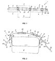
- a strap of the invention comprises an elongate flexible member 2 designed to be secured to a bag B or the like, and having a first portion 3 of adjustable length I 1 which is designed to lie upon the shoulders of a user U and a second portion 4 of adjustable length I 2 which is designed to encircle the waist of the user U and thereby stabilize the bag B and hold it tight thereagainst.
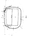
- a bag B or a similar container designed to receive the strap 1 of the invention mounted thereon may be carried in a substantially vertical position at a side of a user U with the strap 1 lying upon one of his/her shoulders.
- the second adjustable portion 4 of the elongate member 2 may not encircle the waist of the user U and may be kept free.
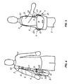
- the strap 1 may be worn with the first adjustable portion 3 obliquely lying upon the shoulder and around the torso of the user U.
- the second adjustable portion 4 may encircle the waist of the user U and be locked at the front.
- the bag B will stably fit at the back of the user U and be comfortably held in position thereupon.
- the elongate flexible member 2 may include first and second bands 5, 6 having respective first ends 7, 8 facing and slideably secured to each other at the first adjustable portion 3 and second free ends 9, 10 at the second adjustable portion 4.
- first and second adjustment means 11, 12 may be provided for adjusting the lengths I 1 , I 2 of the first adjustable portion 3 and the second adjustable portion 4 respectively.
- the first adjustment means 11 may be adjusted independent of the second adjustment means 12.
- the length I 1 of the first adjustable portion 3 may be changed while leaving the length I 2 of the second adjustable portion 4 unchanged.
- the first adjustment means 11 may include first and second sliders 13, 14, which are adapted to longitudinally slide along first ends 7, 9 of the first and second bands 5, 6 respectively.
- the second adjustment means 12 may include a third slider 15 which is adapted to longitudinally slide along the second end 9 of the first band 5 to change the portion 16 of the first band 5 facing the second 6, thereby adjusting the length I 2 of the second adjustable portion 5 of the elongate member 2 to fit the anatomy of the user U and particularly his/her waist size.
- the sliders 13, 14, 15 may be substantially similar, and consist of a substantially plate-like body of metal, plastic or another material with adequate mechanical properties, having a pair of substantially transverse slots 17, 18 and of a substantially central transverse stem 19.
- the slots 17, 18 are designed to receive the ends 7, 8, 9, 10 of the first and second bands 5, 6 respectively.
- the first ends 7, 8 of the first and second bands 5, 6 will engage the first and second sliders 13, 14 respectively, whereas the third slider 15 may be engaged by the second ends 9, 10.
- the second end 10 of the second band 6 may be stably attached to the third slider 15, for example it may be bent into a U shape around the central stem 19 and fixed by sewing or other chemical or mechanical bond.
- the second ends 9, 10 of the first and second bands 5, 6 may be held in mutually facing relation by a loop 20, a tie or the like, slideably mounted thereon.
- the strap 1 may have coupling means 21 for securing it to a bag B or the like, that can be associated with the first and second bands 5, 6 to delimit the first adjustable portion 3 of the elongate member 2.
- the coupling means 21 may include a pair of flaps 22, 23 each having one end, 24 and 25 respectively, adapted to be attached to a bag B or the like by known arrangements, and the opposite end, 26 and 27 respectively, having a passage 28, 29 for corresponding second ends 9, 10 of the first and second bands 5, 6.
- first adjustable portion 3 may be defined by the sections of the first and second bands 5, 6 delimited by the passages 28, 29 of the flaps 22, 23, whereas the second adjustable portion 6 may be defined by the sections of the first and second bands 5, 6 outside such passages 28, 29.
- the latter may be advantageously designed to lock the sliders 13, 14, 15 and prevent them from moving from one side of the flaps 22, 23 to the other.
- the first adjustable portion 3 of the elongate member 2 may substantially coincide with the sections of the first 5 and second bands 6 delimited by the first and second sliders 13, 14.
- the length I 1 of the first portion 3 will be in any case equal to the length of the portion of the elongate member 2 delimited by the two passages 28, 29.
- the length I 2 of the second adjustable portion 4 will correspond to the overall length of the portions of the elongate member 2 outside the passages 28, 29, possibly without the part of the first end 8 of the second band 6 that faces the first end 7 of the first band 5, or vice versa.
- the length I 2 of the second adjustable portion 4 will be simply adjusted by sliding the third slider 15 along the first band 5 to change the portion 16 of the first band 5 overlying the second band 6.
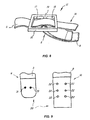
- mutual attachment means 30 may be provided for joining together the first ends 7, 8 of the first and second bands 5, 6 and allow a user U to attach them at the waist, preferably but without limitation at the front.
- the attachment means 30 may include at least one male member 31 on one of the first ends 7, 8 and at least one female receptacle 32 on the other first end 7, 8, for snap engagement with a male member 31.
- a pair of transversely spaced male members 31 are provided on the first end 7 of the first band 5, and three pairs of longitudinally spaced female receptacles 32 are formed on the first end 8 of the second band 6. This will afford further customization of the attachment of the second portion 4 to fit the anatomy and preferences of the user U.
- attachment means 30 may be other than that described and shown herein.
- Both the male members 32 and the female receptacles 32 may be provided in greater or smaller numbers as compared with the illustrated arrangement and may be formed on either or both bands 5, 6, in any spatial arrangement.
- attachment means 30 as shown herein may be replaced by any other type of attachment means, as typically used in the manufacture of straps, belts or similar accessories to be mounted to bags or other clothing items.
- the strap 1 may be also equipped with a shoulder pad 33, e.g. slideably mounted to the first band 5 at the first adjustable portion 3 and designed to contact the shoulder of the user U for improved comfort of the strap 1.
- a shoulder pad 33 e.g. slideably mounted to the first band 5 at the first adjustable portion 3 and designed to contact the shoulder of the user U for improved comfort of the strap 1.
- the materials used for the strap 1 may be selected from the group comprising leather, natural or synthetic fabric or nonwoven fabrics, and may be possibly supplemented with reinforcements of relatively stiff materials, such as metal or rigid plastic.
- the two bands 5, 6 may be also formed of different materials, and each may also comprise several materials at the same time.
- the invention fulfils the intended objects and particularly meets the requirement of providing an adjustable strap for carrying bags and the like that can be also used by a user riding a bicycle or a motorcycle, while still ensuring stability and tight fit of the bag against the user's body.
- the belt may be adjusted to fit various modes of use.
- the strap of the invention is susceptible of a number of changes and variants, within the inventive concept disclosed in the appended claims. All the details thereof may be replaced by other technically equivalent parts, and the materials may vary depending on different needs, without departure from the scope of the invention.
Landscapes
- Purses, Travelling Bags, Baskets, Or Suitcases (AREA)
- Transition And Organic Metals Composition Catalysts For Addition Polymerization (AREA)
- Bag Frames (AREA)
- Supplying Of Containers To The Packaging Station (AREA)
- Belt Conveyors (AREA)
Claims (12)
- Sangle réglable pour porter des sacs ou similaires, en particulier pour des utilisateurs conduisant des bicyclettes ou des motocycles, comprenant un élément flexible allongé (2) pouvant être attaché à un sac (B) ou similaire, ledit élément flexible allongé (2) ayant une première portion (3) de longueur réglable (11) qui est conçue pour reposer sur les épaules d'un utilisateur (U) et une deuxième portion (4) de longueur réglable (12) qui est conçue pour entourer la taille de l'utilisateur (U) en stabilisant ainsi le sac (B) et en le maintenant serré contre celui-ci, caractérisée en ce que ledit élément flexible allongé (2) comprend des première (5) et deuxième (6) bandes ayant des premières extrémités respectives (7. 8) faisant face et fixées de manière coulissante l'une à l'autre au niveau de ladite première portion réglable (3) et des deuxièmes extrémités libres (9. 10) au niveau de ladite deuxième portion réglable (4).
- Sangle réglable selon la revendication 1, caractérisée en ce qu'elle comprend des premiers moyens de réglage (11) pour régler la longueur (U) de ladite première portion réglable (3) et des deuxièmes moyens de réglage (12) pour régler ladite deuxième portion réglable (4), lesdits premiers moyens de réglage (11) étant conçus pour régler la longueur (11) de ladite première portion réglable (3), tout en laissant inchangée la longueur (12) de ladite deuxième portion réglable (4).
- Sangle réglable selon la revendication 2, caractérisée en ce que lesdits premiers moyens de réglage (11) comprennent des première (13) et deuxième (14) glissières qui sont adaptées pour coulisser longitudinalement le long des premières extrémités (7, 8) desdites première (5) et deuxième (6) bandes respectivement.
- Sangle réglable selon la revendication 3, caractérisée en ce que lesdits deuxièmes moyens de réglage (13) comprennent une troisième glissière (15), qui est adaptée pour coulisser longitudinalement le long de ladite deuxième extrémité (9) de ladite première bande (5) pour faire varier la portion (16) de ladite première bande (5) faisant face à la deuxième bande (6) et régler la longueur (12) de ladite deuxième portion réglable (4) dudit élément allongé (2).
- Sangle réglable selon la revendication 4 caractérisée en ce que ladite deuxième extrémité (10) de ladite deuxième bande (6) est fixée de manière permanente à ladite troisième glissière (15).
- Sangle réglable selon une ou plusieurs des revendications précédentes, caractérisée en ce qu'elle comprend des moyens d'accouplement (21) pour fixer ladite première (5) et ladite deuxième (6) bandes (6) à un sac (B) ou similaire, lesdits moyens d'accouplement (21) étant adaptés pour être associés auxdites première et deuxième bandes (5, 6) pour délimiter ladite première portion réglable (3) dudit élément allongé (2).
- Sangle réglable selon la revendication 6, caractérisée en ce que lesdits moyens d'accouplement (21) comprennent au moins une paire de volets (22, 23) ayant chacun une extrémité (24, 25) adaptée pour être attaché à un sac (B) ou similaire et l'extrémité opposée libre (26, 27) ayant un passage (28, 29) pour des deuxièmes extrémités correspondantes (9, 10) desdites première et deuxième bandes (5, 6).
- Sangle réglable selon la revendication 8, caractérisée en ce que ladite première portion réglable (3) est définie par les sections desdites première et deuxième bandes (5, 6) délimitées par lesdits passages (28, 29) desdits volets (22. 23), alors que ladite deuxième portion réglable (5) est définie par les sections desdites première et deuxième bandes (5, 6) à l'extérieur de ces passages (28, 29).
- Sangle réglable selon une ou plusieurs des revendications précédentes, caractérisée en ce que lesdites glissières (13, 14, 15) ont sensiblement une forme de plaque d'épaisseur prédéterminée (s) avec une tige transversale sensiblement centrale (19) et une paire de fentes transversales (17, 18) pour recevoir lesdites premières et deuxièmes extrémités (7, 8. 9, 10) desdites bandes (5, 6).
- Sangle réglable selon une ou plusieurs des revendications précédentes, caractérisée en ce que lesdites premières extrémités (7, 8) desdites bandes (5, 6) ont des moyens de fixation mutuels (30) pour permettre à un utilisateur (U) de les unir entre elles au niveau de la taille.
- Sangle réglable selon la revendication 10, caractérisée en ce que lesdits moyens de fixation (30) comprennent au moins un élément mâle (31) sur une desdites premières extrémités (7, 8) et au moins un réceptacle femelle (32) sur l'autre première extrémité ( 7 , 8 ), pour un engagement par encliquetage avec ledit au moins un élément mâle (31).
- Sangle réglable selon la revendication 11, caractérisée en ce que lesdits moyens de fixation (30) comprennent une pluralité desdits réceptacles femelles (32) dans une relation espacée longitudinalement pour permettre une fixation personnalisée dudit au moins un élément mâle (31) pour s'adapter à la dimension du corps de l'utilisateur (U).
Applications Claiming Priority (2)
| Application Number | Priority Date | Filing Date | Title |
|---|---|---|---|
| IT000232A ITVI20070232A1 (it) | 2007-08-09 | 2007-08-09 | Cinghia regolabile per il trasporto di borse e similari. |
| PCT/IB2008/053188 WO2009019666A2 (fr) | 2007-08-09 | 2008-08-08 | Ceinture ajustable servant à transporter des sacs ou similaires |
Publications (2)
| Publication Number | Publication Date |
|---|---|
| EP2178413A2 EP2178413A2 (fr) | 2010-04-28 |
| EP2178413B1 true EP2178413B1 (fr) | 2011-04-13 |
Family
ID=40174806
Family Applications (1)
| Application Number | Title | Priority Date | Filing Date |
|---|---|---|---|
| EP08807271A Active EP2178413B1 (fr) | 2007-08-09 | 2008-08-08 | Ceinture ajustable servant à transporter des sacs ou similaires |
Country Status (9)
| Country | Link |
|---|---|
| US (1) | US9635920B2 (fr) |
| EP (1) | EP2178413B1 (fr) |
| JP (1) | JP5524057B2 (fr) |
| CN (1) | CN101742940B (fr) |
| AT (1) | ATE505103T1 (fr) |
| DE (1) | DE602008006201D1 (fr) |
| IT (1) | ITVI20070232A1 (fr) |
| TW (1) | TWI474793B (fr) |
| WO (1) | WO2009019666A2 (fr) |
Families Citing this family (3)
| Publication number | Priority date | Publication date | Assignee | Title |
|---|---|---|---|---|
| CN102078068A (zh) * | 2009-11-30 | 2011-06-01 | 完颜章伟 | 一种带止滑肩垫的包带 |
| CN109847161B (zh) * | 2019-02-19 | 2024-07-02 | 南京市江宁医院 | 一种便携式氧疗机 |
| US20210186170A1 (en) * | 2019-12-20 | 2021-06-24 | Newlight Technologies, Inc. | Multi-functional strap for providing various personal item carrying configurations |
Family Cites Families (29)
| Publication number | Priority date | Publication date | Assignee | Title |
|---|---|---|---|---|
| US1302312A (en) * | 1918-12-06 | 1919-04-29 | Jay J Cook | Fish-basket or creel supporting harness. |
| US2691399A (en) * | 1952-09-04 | 1954-10-12 | Tompkins Donald Eugene | Quiver construction |
| US3957183A (en) * | 1974-03-14 | 1976-05-18 | U.S. Divers Company | Backpack for breathing tanks |
| US4279367A (en) * | 1979-06-26 | 1981-07-21 | Jacobs Michael E | Musical instrument harness |
| CA1175019A (fr) | 1981-01-09 | 1984-09-25 | Murray G.W. Miller | Jeu de sangles pour sac a dos |
| US4819845A (en) * | 1985-03-12 | 1989-04-11 | Byrd Gary S | Ski carrier apparatus |
| US4810102A (en) * | 1987-11-02 | 1989-03-07 | Brell Mar Products, Inc. | Universal sport bag |
| US4887751A (en) * | 1987-12-30 | 1989-12-19 | Michael Lehman | Traveler's organizer bag luggage |
| US4923105A (en) * | 1988-08-08 | 1990-05-08 | Snyder James M | Utility belt |
| JPH02124019U (fr) * | 1989-03-24 | 1990-10-12 | ||
| US5129560A (en) * | 1989-09-15 | 1992-07-14 | Stephanie Herman | Utility bag system |
| US5370286A (en) * | 1993-02-26 | 1994-12-06 | Newman; Arthur J. | Adjustable strap |
| US5437401A (en) * | 1994-02-07 | 1995-08-01 | Seltzer; Richard | Personal harness for carrying articles |
| US5950894A (en) * | 1995-07-07 | 1999-09-14 | Haber; Robert | Backpack assembly |
| US5893503A (en) * | 1997-08-14 | 1999-04-13 | Jean; Antoine | Non-slipping shoulder strap assembly |
| USD420514S (en) * | 1997-08-25 | 2000-02-15 | Morlet Mark A | Chest pack strap system |
| US6164505A (en) * | 1998-04-22 | 2000-12-26 | Holter; Dean S. | Harness for carrying a rigid case |
| US20020145027A1 (en) * | 1999-07-21 | 2002-10-10 | Godshaw Donald E. | Low slung tool carrier |
| US6622899B1 (en) * | 2000-04-28 | 2003-09-23 | Heidi Marie Klindworth-Garron | Accessory bag |
| US7070077B2 (en) * | 2004-01-28 | 2006-07-04 | Buckman Imports, Inc. | Backpack |
| JP2005211630A (ja) * | 2004-02-02 | 2005-08-11 | Yoshimasa Tanaka | 肩掛けベルトが肩滑りしないショルダーバッグ |
| US20050224533A1 (en) * | 2004-04-13 | 2005-10-13 | Mccraney Rick M | Body harness for carrying a long gun |
| US7959046B2 (en) * | 2004-06-14 | 2011-06-14 | Blue Force Gear, Inc. | Methods, systems, and apparatus for providing a multiple position sling for a firearm |
| DE102005025245A1 (de) * | 2005-05-31 | 2006-12-07 | Konrad Eisenach | Verstellbarer Gurt für Umhängetaschen |
| US7909214B2 (en) * | 2005-09-09 | 2011-03-22 | Tough Traveler Ltd. | Shoulder strap and waist belt bag |
| JP3122623U (ja) * | 2006-01-20 | 2006-06-29 | 幸二 間木 | 鞄用肩ベルト |
| US20080006668A1 (en) * | 2006-07-10 | 2008-01-10 | Joseph Michael Nowacki | Carrier for personal electronic and communication devices |
| US8371061B2 (en) * | 2007-06-08 | 2013-02-12 | Jeffrey Lawrence Bergers | Personal fish sack carrier |
| US10098439B2 (en) * | 2013-04-16 | 2018-10-16 | Honeywell International Inc. | One-belt harness |
-
2007
- 2007-08-09 IT IT000232A patent/ITVI20070232A1/it unknown
-
2008
- 2008-08-08 US US12/671,623 patent/US9635920B2/en active Active
- 2008-08-08 JP JP2010519560A patent/JP5524057B2/ja active Active
- 2008-08-08 DE DE602008006201T patent/DE602008006201D1/de active Active
- 2008-08-08 CN CN200880024700.7A patent/CN101742940B/zh active Active
- 2008-08-08 AT AT08807271T patent/ATE505103T1/de not_active IP Right Cessation
- 2008-08-08 WO PCT/IB2008/053188 patent/WO2009019666A2/fr active Application Filing
- 2008-08-08 EP EP08807271A patent/EP2178413B1/fr active Active
- 2008-08-11 TW TW097130483A patent/TWI474793B/zh active
Also Published As
| Publication number | Publication date |
|---|---|
| JP2010535571A (ja) | 2010-11-25 |
| WO2009019666A2 (fr) | 2009-02-12 |
| US9635920B2 (en) | 2017-05-02 |
| ITVI20070232A1 (it) | 2009-02-10 |
| EP2178413A2 (fr) | 2010-04-28 |
| WO2009019666A3 (fr) | 2009-04-02 |
| JP5524057B2 (ja) | 2014-06-18 |
| TWI474793B (zh) | 2015-03-01 |
| ATE505103T1 (de) | 2011-04-15 |
| TW200934410A (en) | 2009-08-16 |
| CN101742940B (zh) | 2014-06-25 |
| CN101742940A (zh) | 2010-06-16 |
| US20110226827A1 (en) | 2011-09-22 |
| DE602008006201D1 (de) | 2011-05-26 |
Similar Documents
| Publication | Publication Date | Title |
|---|---|---|
| US6698636B2 (en) | Waist pouch | |
| US5630536A (en) | Adjustable body pack | |
| US7938302B2 (en) | Wing pocket article carrier | |
| US6837409B2 (en) | Backpack system | |
| US9775428B2 (en) | Portable container holder | |
| US6371346B1 (en) | Interchangeable equipment carrier sling/waist belt | |
| US20080185412A1 (en) | Interchangeable holster with removable pockets | |
| JPH02194288A (ja) | リユツクサツクの支持枠 | |
| US11278105B2 (en) | Combination backpack and baby carrier | |
| US20150108194A1 (en) | Board sport equipment carrier | |
| US9113696B2 (en) | Backpack shoulder strap | |
| US12016447B2 (en) | Configurable bag having faceplates | |
| US8360289B2 (en) | Adjustable waist belt system for a carrying apparatus | |
| EP2178413B1 (fr) | Ceinture ajustable servant à transporter des sacs ou similaires | |
| JP2020018822A (ja) | 背負いかばん | |
| CA2960478A1 (fr) | Harnais ajustable destine a des sacs a dos et methode d'utilisation associee | |
| US20130056508A1 (en) | Carrier | |
| JPH0737531Y2 (ja) | 抱き具の機能を併有するリュックサック | |
| JP5863348B2 (ja) | バックル装置およびバックル装置を取付けた身体装着体 | |
| US20240315428A1 (en) | Configurable bag having faceplates | |
| GB2563673A (en) | Detachable baby carrier | |
| JP3010035U (ja) | ウエストポーチ | |
| CA2284112A1 (fr) | Sacoche de ceinture et sac de guidon combines | |
| JP2013059548A (ja) | リュックサック |
Legal Events
| Date | Code | Title | Description |
|---|---|---|---|
| PUAI | Public reference made under article 153(3) epc to a published international application that has entered the european phase |
Free format text: ORIGINAL CODE: 0009012 |
|
| 17P | Request for examination filed |
Effective date: 20091203 |
|
| AK | Designated contracting states |
Kind code of ref document: A2 Designated state(s): AT BE BG CH CY CZ DE DK EE ES FI FR GB GR HR HU IE IS IT LI LT LU LV MC MT NL NO PL PT RO SE SI SK TR |
|
| AX | Request for extension of the european patent |
Extension state: AL BA MK RS |
|
| RIN1 | Information on inventor provided before grant (corrected) |
Inventor name: BOURGEOIS, VINCENT |
|
| RAP1 | Party data changed (applicant data changed or rights of an application transferred) |
Owner name: BROOKS ENGLAND LIMITED |
|
| GRAP | Despatch of communication of intention to grant a patent |
Free format text: ORIGINAL CODE: EPIDOSNIGR1 |
|
| DAX | Request for extension of the european patent (deleted) | ||
| RIN1 | Information on inventor provided before grant (corrected) |
Inventor name: BOURGEOIS, VINCENT |
|
| GRAS | Grant fee paid |
Free format text: ORIGINAL CODE: EPIDOSNIGR3 |
|
| GRAA | (expected) grant |
Free format text: ORIGINAL CODE: 0009210 |
|
| AK | Designated contracting states |
Kind code of ref document: B1 Designated state(s): AT BE BG CH CY CZ DE DK EE ES FI FR GB GR HR HU IE IS IT LI LT LU LV MC MT NL NO PL PT RO SE SI SK TR |
|
| REG | Reference to a national code |
Ref country code: GB Ref legal event code: FG4D |
|
| REG | Reference to a national code |
Ref country code: CH Ref legal event code: EP |
|
| REG | Reference to a national code |
Ref country code: IE Ref legal event code: FG4D |
|
| REF | Corresponds to: |
Ref document number: 602008006201 Country of ref document: DE Date of ref document: 20110526 Kind code of ref document: P |
|
| REG | Reference to a national code |
Ref country code: DE Ref legal event code: R096 Ref document number: 602008006201 Country of ref document: DE Effective date: 20110526 |
|
| REG | Reference to a national code |
Ref country code: CH Ref legal event code: NV Representative=s name: ISLER & PEDRAZZINI AG |
|
| REG | Reference to a national code |
Ref country code: NL Ref legal event code: T3 |
|
| LTIE | Lt: invalidation of european patent or patent extension |
Effective date: 20110413 |
|
| PG25 | Lapsed in a contracting state [announced via postgrant information from national office to epo] |
Ref country code: LT Free format text: LAPSE BECAUSE OF FAILURE TO SUBMIT A TRANSLATION OF THE DESCRIPTION OR TO PAY THE FEE WITHIN THE PRESCRIBED TIME-LIMIT Effective date: 20110413 Ref country code: PT Free format text: LAPSE BECAUSE OF FAILURE TO SUBMIT A TRANSLATION OF THE DESCRIPTION OR TO PAY THE FEE WITHIN THE PRESCRIBED TIME-LIMIT Effective date: 20110816 Ref country code: SE Free format text: LAPSE BECAUSE OF FAILURE TO SUBMIT A TRANSLATION OF THE DESCRIPTION OR TO PAY THE FEE WITHIN THE PRESCRIBED TIME-LIMIT Effective date: 20110413 Ref country code: NO Free format text: LAPSE BECAUSE OF FAILURE TO SUBMIT A TRANSLATION OF THE DESCRIPTION OR TO PAY THE FEE WITHIN THE PRESCRIBED TIME-LIMIT Effective date: 20110713 Ref country code: HR Free format text: LAPSE BECAUSE OF FAILURE TO SUBMIT A TRANSLATION OF THE DESCRIPTION OR TO PAY THE FEE WITHIN THE PRESCRIBED TIME-LIMIT Effective date: 20110413 |
|
| PG25 | Lapsed in a contracting state [announced via postgrant information from national office to epo] |
Ref country code: IS Free format text: LAPSE BECAUSE OF FAILURE TO SUBMIT A TRANSLATION OF THE DESCRIPTION OR TO PAY THE FEE WITHIN THE PRESCRIBED TIME-LIMIT Effective date: 20110813 Ref country code: CY Free format text: LAPSE BECAUSE OF FAILURE TO SUBMIT A TRANSLATION OF THE DESCRIPTION OR TO PAY THE FEE WITHIN THE PRESCRIBED TIME-LIMIT Effective date: 20110413 Ref country code: LV Free format text: LAPSE BECAUSE OF FAILURE TO SUBMIT A TRANSLATION OF THE DESCRIPTION OR TO PAY THE FEE WITHIN THE PRESCRIBED TIME-LIMIT Effective date: 20110413 Ref country code: ES Free format text: LAPSE BECAUSE OF FAILURE TO SUBMIT A TRANSLATION OF THE DESCRIPTION OR TO PAY THE FEE WITHIN THE PRESCRIBED TIME-LIMIT Effective date: 20110724 Ref country code: GR Free format text: LAPSE BECAUSE OF FAILURE TO SUBMIT A TRANSLATION OF THE DESCRIPTION OR TO PAY THE FEE WITHIN THE PRESCRIBED TIME-LIMIT Effective date: 20110714 Ref country code: AT Free format text: LAPSE BECAUSE OF FAILURE TO SUBMIT A TRANSLATION OF THE DESCRIPTION OR TO PAY THE FEE WITHIN THE PRESCRIBED TIME-LIMIT Effective date: 20110413 Ref country code: BE Free format text: LAPSE BECAUSE OF FAILURE TO SUBMIT A TRANSLATION OF THE DESCRIPTION OR TO PAY THE FEE WITHIN THE PRESCRIBED TIME-LIMIT Effective date: 20110413 Ref country code: FI Free format text: LAPSE BECAUSE OF FAILURE TO SUBMIT A TRANSLATION OF THE DESCRIPTION OR TO PAY THE FEE WITHIN THE PRESCRIBED TIME-LIMIT Effective date: 20110413 Ref country code: SI Free format text: LAPSE BECAUSE OF FAILURE TO SUBMIT A TRANSLATION OF THE DESCRIPTION OR TO PAY THE FEE WITHIN THE PRESCRIBED TIME-LIMIT Effective date: 20110413 |
|
| PG25 | Lapsed in a contracting state [announced via postgrant information from national office to epo] |
Ref country code: MT Free format text: LAPSE BECAUSE OF FAILURE TO SUBMIT A TRANSLATION OF THE DESCRIPTION OR TO PAY THE FEE WITHIN THE PRESCRIBED TIME-LIMIT Effective date: 20110413 |
|
| PG25 | Lapsed in a contracting state [announced via postgrant information from national office to epo] |
Ref country code: CZ Free format text: LAPSE BECAUSE OF FAILURE TO SUBMIT A TRANSLATION OF THE DESCRIPTION OR TO PAY THE FEE WITHIN THE PRESCRIBED TIME-LIMIT Effective date: 20110413 Ref country code: EE Free format text: LAPSE BECAUSE OF FAILURE TO SUBMIT A TRANSLATION OF THE DESCRIPTION OR TO PAY THE FEE WITHIN THE PRESCRIBED TIME-LIMIT Effective date: 20110413 |
|
| PLBE | No opposition filed within time limit |
Free format text: ORIGINAL CODE: 0009261 |
|
| STAA | Information on the status of an ep patent application or granted ep patent |
Free format text: STATUS: NO OPPOSITION FILED WITHIN TIME LIMIT |
|
| PG25 | Lapsed in a contracting state [announced via postgrant information from national office to epo] |
Ref country code: SK Free format text: LAPSE BECAUSE OF FAILURE TO SUBMIT A TRANSLATION OF THE DESCRIPTION OR TO PAY THE FEE WITHIN THE PRESCRIBED TIME-LIMIT Effective date: 20110413 Ref country code: RO Free format text: LAPSE BECAUSE OF FAILURE TO SUBMIT A TRANSLATION OF THE DESCRIPTION OR TO PAY THE FEE WITHIN THE PRESCRIBED TIME-LIMIT Effective date: 20110413 Ref country code: PL Free format text: LAPSE BECAUSE OF FAILURE TO SUBMIT A TRANSLATION OF THE DESCRIPTION OR TO PAY THE FEE WITHIN THE PRESCRIBED TIME-LIMIT Effective date: 20110413 Ref country code: DK Free format text: LAPSE BECAUSE OF FAILURE TO SUBMIT A TRANSLATION OF THE DESCRIPTION OR TO PAY THE FEE WITHIN THE PRESCRIBED TIME-LIMIT Effective date: 20110413 |
|
| 26N | No opposition filed |
Effective date: 20120116 |
|
| PG25 | Lapsed in a contracting state [announced via postgrant information from national office to epo] |
Ref country code: MC Free format text: LAPSE BECAUSE OF NON-PAYMENT OF DUE FEES Effective date: 20110831 |
|
| REG | Reference to a national code |
Ref country code: DE Ref legal event code: R097 Ref document number: 602008006201 Country of ref document: DE Effective date: 20120116 |
|
| REG | Reference to a national code |
Ref country code: IE Ref legal event code: MM4A |
|
| PG25 | Lapsed in a contracting state [announced via postgrant information from national office to epo] |
Ref country code: IE Free format text: LAPSE BECAUSE OF NON-PAYMENT OF DUE FEES Effective date: 20110808 |
|
| PG25 | Lapsed in a contracting state [announced via postgrant information from national office to epo] |
Ref country code: LU Free format text: LAPSE BECAUSE OF NON-PAYMENT OF DUE FEES Effective date: 20110808 |
|
| PG25 | Lapsed in a contracting state [announced via postgrant information from national office to epo] |
Ref country code: BG Free format text: LAPSE BECAUSE OF FAILURE TO SUBMIT A TRANSLATION OF THE DESCRIPTION OR TO PAY THE FEE WITHIN THE PRESCRIBED TIME-LIMIT Effective date: 20110713 |
|
| PG25 | Lapsed in a contracting state [announced via postgrant information from national office to epo] |
Ref country code: TR Free format text: LAPSE BECAUSE OF FAILURE TO SUBMIT A TRANSLATION OF THE DESCRIPTION OR TO PAY THE FEE WITHIN THE PRESCRIBED TIME-LIMIT Effective date: 20110413 |
|
| PG25 | Lapsed in a contracting state [announced via postgrant information from national office to epo] |
Ref country code: HU Free format text: LAPSE BECAUSE OF FAILURE TO SUBMIT A TRANSLATION OF THE DESCRIPTION OR TO PAY THE FEE WITHIN THE PRESCRIBED TIME-LIMIT Effective date: 20110413 |
|
| REG | Reference to a national code |
Ref country code: FR Ref legal event code: PLFP Year of fee payment: 9 |
|
| REG | Reference to a national code |
Ref country code: FR Ref legal event code: PLFP Year of fee payment: 10 |
|
| REG | Reference to a national code |
Ref country code: FR Ref legal event code: PLFP Year of fee payment: 11 |
|
| P01 | Opt-out of the competence of the unified patent court (upc) registered |
Effective date: 20230427 |
|
| PGFP | Annual fee paid to national office [announced via postgrant information from national office to epo] |
Ref country code: NL Payment date: 20230826 Year of fee payment: 16 |
|
| PGFP | Annual fee paid to national office [announced via postgrant information from national office to epo] |
Ref country code: IT Payment date: 20230706 Year of fee payment: 16 Ref country code: GB Payment date: 20230828 Year of fee payment: 16 Ref country code: CH Payment date: 20230903 Year of fee payment: 16 |
|
| PGFP | Annual fee paid to national office [announced via postgrant information from national office to epo] |
Ref country code: FR Payment date: 20230825 Year of fee payment: 16 Ref country code: DE Payment date: 20230829 Year of fee payment: 16 |