EP2178177B1 - Shield connector - Google Patents
Shield connector Download PDFInfo
- Publication number
- EP2178177B1 EP2178177B1 EP08791962.7A EP08791962A EP2178177B1 EP 2178177 B1 EP2178177 B1 EP 2178177B1 EP 08791962 A EP08791962 A EP 08791962A EP 2178177 B1 EP2178177 B1 EP 2178177B1
- Authority
- EP
- European Patent Office
- Prior art keywords
- shielded
- conductor
- tubular connection
- connection portion
- portions
- Prior art date
- Legal status (The legal status is an assumption and is not a legal conclusion. Google has not performed a legal analysis and makes no representation as to the accuracy of the status listed.)
- Not-in-force
Links
- 239000004020 conductor Substances 0.000 claims description 362
- 238000002788 crimping Methods 0.000 claims description 249
- 238000000034 method Methods 0.000 claims description 77
- 230000006835 compression Effects 0.000 description 25
- 238000007906 compression Methods 0.000 description 25
- 238000005452 bending Methods 0.000 description 7
- 230000006866 deterioration Effects 0.000 description 3
- 230000005540 biological transmission Effects 0.000 description 2
- 230000005674 electromagnetic induction Effects 0.000 description 2
- 239000000463 material Substances 0.000 description 2
- 238000010276 construction Methods 0.000 description 1
- 239000011347 resin Substances 0.000 description 1
- 229920005989 resin Polymers 0.000 description 1
Images




Classifications
-
- H—ELECTRICITY
- H01—ELECTRIC ELEMENTS
- H01R—ELECTRICALLY-CONDUCTIVE CONNECTIONS; STRUCTURAL ASSOCIATIONS OF A PLURALITY OF MUTUALLY-INSULATED ELECTRICAL CONNECTING ELEMENTS; COUPLING DEVICES; CURRENT COLLECTORS
- H01R13/00—Details of coupling devices of the kinds covered by groups H01R12/70 or H01R24/00 - H01R33/00
- H01R13/648—Protective earth or shield arrangements on coupling devices, e.g. anti-static shielding
- H01R13/658—High frequency shielding arrangements, e.g. against EMI [Electro-Magnetic Interference] or EMP [Electro-Magnetic Pulse]
- H01R13/6591—Specific features or arrangements of connection of shield to conductive members
- H01R13/6592—Specific features or arrangements of connection of shield to conductive members the conductive member being a shielded cable
- H01R13/6593—Specific features or arrangements of connection of shield to conductive members the conductive member being a shielded cable the shield being composed of different pieces
-
- H—ELECTRICITY
- H01—ELECTRIC ELEMENTS
- H01R—ELECTRICALLY-CONDUCTIVE CONNECTIONS; STRUCTURAL ASSOCIATIONS OF A PLURALITY OF MUTUALLY-INSULATED ELECTRICAL CONNECTING ELEMENTS; COUPLING DEVICES; CURRENT COLLECTORS
- H01R13/00—Details of coupling devices of the kinds covered by groups H01R12/70 or H01R24/00 - H01R33/00
- H01R13/648—Protective earth or shield arrangements on coupling devices, e.g. anti-static shielding
- H01R13/658—High frequency shielding arrangements, e.g. against EMI [Electro-Magnetic Interference] or EMP [Electro-Magnetic Pulse]
- H01R13/6591—Specific features or arrangements of connection of shield to conductive members
- H01R13/65912—Specific features or arrangements of connection of shield to conductive members for shielded multiconductor cable
- H01R13/65915—Twisted pair of conductors surrounded by shield
-
- H—ELECTRICITY
- H01—ELECTRIC ELEMENTS
- H01R—ELECTRICALLY-CONDUCTIVE CONNECTIONS; STRUCTURAL ASSOCIATIONS OF A PLURALITY OF MUTUALLY-INSULATED ELECTRICAL CONNECTING ELEMENTS; COUPLING DEVICES; CURRENT COLLECTORS
- H01R13/00—Details of coupling devices of the kinds covered by groups H01R12/70 or H01R24/00 - H01R33/00
- H01R13/646—Details of coupling devices of the kinds covered by groups H01R12/70 or H01R24/00 - H01R33/00 specially adapted for high-frequency, e.g. structures providing an impedance match or phase match
- H01R13/6461—Means for preventing cross-talk
- H01R13/6463—Means for preventing cross-talk using twisted pairs of wires
-
- H—ELECTRICITY
- H01—ELECTRIC ELEMENTS
- H01R—ELECTRICALLY-CONDUCTIVE CONNECTIONS; STRUCTURAL ASSOCIATIONS OF A PLURALITY OF MUTUALLY-INSULATED ELECTRICAL CONNECTING ELEMENTS; COUPLING DEVICES; CURRENT COLLECTORS
- H01R13/00—Details of coupling devices of the kinds covered by groups H01R12/70 or H01R24/00 - H01R33/00
- H01R13/648—Protective earth or shield arrangements on coupling devices, e.g. anti-static shielding
- H01R13/6485—Electrostatic discharge protection
Definitions
- the present invention relates to a wiring harness of an automobile and more particularly to a shielded connector to be connected to a shielded cable such as a shielded twisted-pair wire and a coaxial cable which are transmission cables for use in a LAN system mounted on a vehicle.
- a shielded cable such as a shielded twisted-pair wire and a coaxial cable which are transmission cables for use in a LAN system mounted on a vehicle.
- a shielded twisted-pair wire called STP has a shielded conductor in which a twisted wire of two signal wires is used. It is characterized in that the two signal wires are arranged to be adjacent to each other by being twisted so that a loop is formed at which a magnetic field of opposite polarities is generated and the thus generated polarities are cancelled with each other, whereby an influence of electromagnetic induction can be reduced. It is known that if the wire is covered with a shielded conductor, the wire radiates less electromagnetic induction noise to the outside and receives less noise from the outside, and therefore, the wire is widely used as a LAN cable for high-speed transmission.
- This kind of shielded twisted-pair wire is usually subjected to terminal processing and is connected to a dedicated connector called a modular connector.
- a vehicle-mounted network of an electronic appliance such as a vehicle-mounted car navigation system is provided by using this kind of shielded twisted-pair wire.
- JP 07-018379 A An example of a shield connection between a shielded conductor of the shielded twisted-pair wire and an outer conductor shell of a shielded connector usually used in an automobile or others is disclosed in JP 07-018379 A .
- a crimp portion provided to the outer conductor shell is crimped onto the shielded conductor which is exposed by stripping off a portion of a sheath.
- the crimping process is performed with high pressure, twisted signal wires in the shielded conductor become flat, which leads to deterioration in high frequency characteristics.
- pressure applied during the crimping process should be low, which results in low pull-out strength of the wire against the connector and a failure to achieve sufficient contact load to satisfy connection reliability for the wire to be used in a vibrating automotive vehicle.
- EP 0 800 238 A2 discloses a shield for a modular electrical connector.
- the shield houses the connector in a box-like fashion and has an openable lid for inserting the connector.
- a crimp portion at the lid is fixed at an outer sheath of a cable extending from the connector.
- EP 0 125 760 A1 discloses a connector plug having a shielding enclosure. Also in this shield enclosure a box-like shield houses the connector and a crimp portion at the enclosure is fixed at an outer sheath of a cable extending from the connector.
- EP 0 125 760 A1 A similar construction to EP 0 125 760 A1 is disclosed in US 5 725 395 A or in EP 1 003 249 A1
- EP 0 040 941 discloses an electrical connector shield.
- a shield houses the connector in a box-like fashion.
- the shield is made from two housing or box parts and a crimp portion at the shield is for fixing the shield at an outer sheath of a cable extending from the connector.
- US 6 059 607 A shows a shielded electrical connector.
- Two shielding housing halves are mounted in a swingable manner at a plate member and are for accommodating connectors at free ends of cables or wires.
- Each housing halve comprises a pair of crimping fingers for embracing the cable/the wires. With the housing halves being closed, the two pairs of crimping fingers are intercalated with each other along the length direction of the cable/the wires.
- An object of the present invention is to overcome the problems described above and to provide a shielded connector which can achieve sufficient contact load between a shielded conductor and a crimp portion of an outer conductor shell without having an influence such as deformation of cross sections on signal wires when the crimp portion of the outer conductor shell is crimped onto the shielded conductor, and to achieve enhanced pull-out strength of a shielded cable against the outer conductor shell.
- the present invention provides a shielded connector to be connected to an end portion of a shielded cable having a signal wire, wherein either an outer conductor shell comprises fitting spaces provided to an inside of shielded conductor crimping portions at positions opposed to a tubular connection portion and upper ends of the tubular connection portion and a shielded conductor are inserted into the fitting spaces during the crimping process, or the outer conductor shell comprises a projection portion provided to a top wall of the tubular connection portion at a position opposed to the shielded conductor crimping portions and a fitting hole provided to the shielded conductor crimping portions opposed to the projection portion, wherein the projection portion and the shielded conductor are inserted into the fitting hole during the crimping process.
- the tubular connection portion has an arc angle of 180 degrees or more in cross section before the crimping process. Further, it may be preferable that the fitting spaces are provided by forming a concave portion that extends inward and is defined by a portion of the shielded conductor crimping portions.
- projection portions are provided to the lower ends of the shielded conductor crimping portions, and the projection portions and the shielded conductor are inserted into the fitting hole provided to the bottom wall of the tubular connection portion while tips of the projection portions come into contact with each other to bend the projection portions during the crimping process.
- a fitting hole is provided to the bottom wall of the tubular connection portion, and lower ends of the sheath crimping portions and the shielded conductor are inserted into the fitting hole while the sheath crimping portions are bent to break through the sheath, which prevents lifting caused by spring-back of the sheath crimping portions after the crimping process.
- an outer diameter of a portion of the tubular connection portion onto which the shielded conductor crimping portions are crimped and an outer diameter of a portion of the tubular connection portion onto which the sheath crimping portions are crimped are made substantially equal to an inner diameter of the shielded conductor.
- projection portions are provided to the lower ends of the shielded conductor crimping portions, and the projection portions and the shielded conductor are inserted into the fitting hole provided to the bottom wall of the tubular connection portion while tips of the projection portions come into contact with each other to bend the projection portions during the crimping process.
- a fitting hole is provided to the bottom wall of the tubular connection portion, and the projection portions of the sheath crimping portions and the shielded conductor are inserted into the fitting hole provided to the bottom wall of the tubular connection portion while the projection portions are bent to break through the sheath, which prevents lifting caused by spring-back of the sheath crimping portions after the crimping process.
- the shielded connector according to the present invention has the configuration in which the outer conductor shell includes the tubular connection portion having an arc shape in cross section and arranged to be inserted into the end portion of the shielded conductor which is exposed by stripping off the portion of the sheath at the end portion of the shielded cable and into the end portion of the sheath, the shielded conductor crimping portions arranged to be crimped onto the end portion of the shielded conductor into which the tubular connection portion has been inserted, and the sheath crimping portions arranged to be crimped onto the end portion of the sheath into which the tubular connection portion has been inserted, wherein the tubular connection portion and the shielded conductor crimping portions together have a circle shape in cross section after the crimping process.
- the shielded conductor crimping portions can exert compression force in normal direction to the outer surface of the tubular connection portion on the shielded conductor located on the tubular connection portion without having an influence such as deformation of cross sections on the signal wires in the shielded conductor, whereby enhanced connection reliability among the tubular connection portion, the shielded conductor and the shielded conductor crimping portions is achieved. Further, the sheath crimping portions to be crimped onto the end portion of the sheath into which the tubular connection portion has been inserted are opposed to the tubular connection portion.
- the sheath crimping portions can exert compression force in normal direction to the outer surface of the tubular connection portion on the sheath located on the tubular connection portion, whereby improved connection reliability against bending stress of the shielded cable as well as enhanced pull-out strength of the shielded cable are achieved.
- the tubular connection portion has an arc shape, i.e., an arc shape in cross section. Accordingly, uniform compression stress is developed in the cross section, whereby the tubular connection portion is not bent in its middle portion and shows high mechanical strength after being deformed by the crimping process.
- the outer conductor shell having the configuration described above is comprised of two members, one having the tubular connection portion and the other having the shielded conductor crimping portions and the sheath crimping portions. Accordingly, the number of members comprising the outer conductor shell can be minimized.
- the tubular connection portion having an arc angle of 180 degrees or more in cross section before the crimping process is deformed during the crimping process and becomes to have a circle shape in cross section after the crimping process, whereby the possibility that the signal wires located in the tubular connection portion may be influenced by deformation of cross sections is eliminated.
- the tubular connection portion having an arc angle of 180 degrees or more in cross section before the crimping process uniform compression stress is developed in the cross section during the crimping process, whereby the tubular connection portion is not bent in its middle portion.
- the shielded conductor crimping portions can further exert compression force in tangential direction to the outer surface of the tubular connection portion on the shielded conductor located on the tubular connection portion, whereby enhanced pull-out strength of the shielded conductor as well as improved connection reliability among the tubular connection portion, the shielded conductor and the shielded conductor crimping portions are achieved.
- the fitting spaces of the shielded conductor crimping portions are provided by forming the concave portion that extends inward and is defined by the portion of the shielded conductor crimping portions, the fitting spaces can be provided to the inside of the shielded conductor crimping portions with a simple manner.
- the concave portion is also brought into contact with the shielded conductor, whereby enhanced pull-out strength of the shielded conductor as well as improved connection reliability are achieved.
- the shielded conductor crimping portions can further exert compression force in tangential direction to the outer surface of the tubular connection portion on the shielded conductor located on the tubular connection portion, whereby enhanced pull-out strength of the shielded conductor as well as improved connection reliability among the tubular connection portion, the shielded conductor and the shielded conductor crimping portions are achieved.
- this arrangement also prevents lifting caused by spring-back of the shielded conductor crimping portions after the crimping process.
- the projection portions are provided to the lower ends of the shielded conductor crimping portions and the projection portions and the shielded conductor are inserted into the fitting hole provided to the bottom wall of the tubular connection portion while the tips of the projection portions come into contact with each other to bend the projection portions during the crimping process, the shielded conductor can be smoothly guided into the fitting hole and the tips of the projection portions can hold the shielded conductor at the fitting hole without fail, whereby the shielded conductor at the fitting hole can be held without fail.
- the sheath crimping portions can further exert compression force in tangential direction to the outer surface of the tubular connection portion on the shielded conductor and the sheath that are located on the tubular connection portion, whereby connection of the tubular connection portion, the shielded conductor and the sheath crimping portions is achieved.
- enhanced pull-out strength of the shielded cable and improved connection reliability against bending stress of the shielded cable are achieved. This arrangement also prevents lifting caused by spring-back of the sheath crimping portions after the crimping process.
- the shielded connector according to another preferred embodiment of the present invention having the configuration described above includes the outer conductor terminal including the tubular connection portion having an arc shape in cross section and arranged to be inserted into the end portion of the shielded conductor which is exposed by stripping off the portion of the sheath at the end portion of the shielded cable and into the end portion of the sheath, the shielded conductor crimping portions opposed to the tubular connection portion and arranged to be crimped onto the end portion of the shielded conductor into which the tubular connection portion has been inserted, and the sheath crimping portions opposed to the tubular connection portion and arranged to be crimped onto the end portion of the sheath into which the tubular connection portion has been inserted, wherein the tubular connection portion and the shielded conductor crimping portions together have a circle shape in cross section after the crimping process.
- the shielded conductor crimping portions can exert compression force in normal direction to the outer surface of the tubular connection portion on the shielded conductor located on the tubular connection portion without having an influence such as deformation of cross sections on the signal wires in the shielded conductor, whereby improved connection reliability among the tubular connection portion, the shielded conductor and the shielded conductor crimping portions is achieved.
- the sheath crimping portions to be crimped onto the end portion of the sheath into which the tubular connection portion has been inserted are opposed to the tubular connection portion.
- the sheath crimping portions can exert compression force in normal direction to the outer surface of the tubular connection portion on the sheath located on the tubular connection portion, whereby improved connection reliability against bending stress of the shielded cable as well as enhanced pull-out strength of the shielded cable are achieved.
- the tubular connection portion has a circle shape in cross section. Accordingly, uniform compression stress is developed in the cross section, whereby the tubular connection portion is not bent in its middle portion and shows high mechanical strength after being deformed by the crimping process.
- the outer conductor shell having the configuration described above is comprised of two members, one having the tubular connection portion and the other having the shielded conductor crimping portions and the sheath crimping portions. Accordingly, the number of members comprising the outer conductor shell can be minimized.
- the outer diameter of the portion of the tubular connection portion onto which the shielded conductor crimping portions are crimped and the outer diameter of the portion of the tubular connection portion onto which the sheath crimping portions are crimped are made substantially equal to an inner diameter of the shielded conductor, if the shielded conductor consists of a braided wire of a plurality of elemental wires, the shielded conductor consisting of the braided wire is not necessary to be enlarged for receiving therein the tubular connection portion, whereby the tubular connection portion can be easily inserted into the shielded conductor. If the inner diameter of the shielded conductor consisting of the braided wire is enlarged, picks of the elemental wires are frayed.
- the outer diameter of the tubular connection portion having a circle shape in cross section is made substantially equal to the inner diameter of the shielded conductor consisting of a braided wire, picks of the elemental wires are not frayed. Accordingly, the shielded conductor crimping portions can be crimped uniformly onto the shielded conductor, whereby enhanced pull-out strength of the shielded conductor as well as improved connection reliability among the tubular connection portion, the shielded conductor and the shielded conductor crimping portions are achieved.
- the projection portion is provided to the top wall of the tubular connection portion at the position opposed to the shielded conductor crimping portions
- the fitting hole is provided to the shielded conductor crimping portions opposed to the projection portion, and the projection portion and the shielded conductor are inserted into the fitting hole during the crimping process, enhanced pull-out strength of the shielded conductor as well as improved connection reliability among the tubular connection portion, the shielded conductor and the shielded conductor crimping portions are achieved.
- the shielded conductor crimping portions can further exert compression force in tangential direction to the shielded conductor on the tubular connection portion, whereby enhanced pull-out strength of the shielded conductor as well as improved connection reliability of the tubular connection portion, the shielded conductor and the shielded conductor crimping portions are achieved.
- This arrangement also prevents lifting caused by spring-back of the shielded conductor crimping portions after the crimping process.
- the projection portions are each provided to the lower ends of the shielded conductor crimping portions, and the projection portions and the shielded conductor are inserted into the fitting hole provided to the bottom wall of the tubular connection portion while the tips of the projection portions come into contact with each other to bend the projection portions during the crimping process, the shielded conductor can be smoothly guided into the fitting hole and the tips of the projection portions can hold the shielded conductor at the fitting hole without fail, whereby the shielded conductor at the fitting hole can be held without fail.
- the sheath crimping portions can further exert compression force in tangential direction on the shielded conductor and the sheath that are located on the tubular connection portion, whereby the sheath crimping portions and the shielded conductor are brought into contact with each other.
- improved connection reliability against bending stress of the shielded cable as well as enhanced pull-out strength of the shielded cable are achieved. This arrangement also prevents lifting caused by spring-back of the sheath crimping portions after the crimping process.
- the shielded connector according to the preferred embodiments of the present invention is used for a multi-contact shielded cable having a plurality of signal wires and is especially used for a shielded twisted-pair wire having six signal wires.
- the side of the shielded conductor to which a corresponding connector (not shown) is fitted is referred to as the front side.
- the shielded connector 1 to be connected to an end portion of a shielded twisted-pair wire W includes inner conductor terminals 2, an inner housing 3, and the outer conductor shell 4.
- the inner conductor terminals 2 are connected to signal conductors Wb of signal wires Wa of the shielded twisted-pair wire W to transmit high-frequency signals and have a so-called female terminal shape.
- the inner housing 3 arranged to house the inner conductor terminals 2 provides an insulating state between the inner conductor terminals 2 and the outer conductor shell 4 and is made from a resin insulating member having a predetermined dielectric constant.
- the inner conductor terminals 2 are inserted into the inner housing 3 from the back side to be secured.
- the outer conductor shell 4 is connected to a shielded conductor Wd of the shielded twisted-pair wire W and covers the inner conductor terminals 2 to electromagnetically shield the inner conductor terminals 2.
- the outer conductor shell 4 includes an outer conductor case 5 and an outer conductor cover 6 arranged to be assembled with the outer conductor case 5.
- the outer conductor case 5 has a substantially cylindrical shape and is prepared by bending a conductive plate material.
- a main portion 5a of the outer conductor case 5 is arranged to house the inner housing 3 inside.
- an opening portion 5b is provided in order to allow the inner housing 3 to be easily housed in the main portion 5a.
- concave portions 5c, 5c are provided with which bent portions 6c, 6c of the outer conductor cover 6 assembled as shown in Fig. 2 are to be engaged.
- engagement portions 5d, 5d are provided to project obliquely inward and are arranged to be engaged with the top surface of a flat portion 6d of the outer conductor cover 6 assembled as shown in Fig. 2 so as to prevent the outer conductor cover 6 from being easily disengaged from the outer conductor case 5.
- a tubular connection portion 7 that opens upward and has an arc shape in cross section is provided. As shown in Fig. 3 , the tubular connection portion 7 is covered with the shielded conductor Wd onto which a pair of shielded conductor crimping portions 8a, 8a and a pair of sheath crimping portions 8b, 8b of the outer conductor cover 6 are crimped.
- the tubular connection portion 7 includes a large-diameter portion 7a onto which the shielded conductor crimping portions 8a, 8a are to be crimped and a small-diameter portion 7b onto which the sheath crimping portion 8b, 8b are to be crimped.
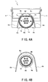
- the large-diameter portion 7a of the tubular connection portion 7 preferably has an arc angle of 180 degrees or more in cross section, and in the first preferred embodiment, the arc angle is about 270 degrees as shown in Fig. 4A .
- a fitting hole 7d is provided in a bottom wall of the large-diameter portion 7a to run through the bottom wall.
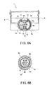
- Projection portions 8c, 8c are provided to the shielded conductor crimping portions 8a, 8a of the outer conductor cover 6 as shown in Fig. 4A , and the projection portions 8c, 8c and the shielded conductor Wd are inserted into the fitting hole 7d during the crimping process (see Fig. 6A ).
- the shielded conductor Wd is fixed to the large-diameter portion 7a by the crimping of the shielded conductor crimping portions 8a, 8a.
- the small-diameter portion 7b of the tubular connection portion 7 has an arc angle of about 180 degrees in cross section as shown in Fig. 4B . Owing to the small-diameter portion 7b having an arch shape in cross section, uniform compression stress is developed in the cross section during the crimping process, whereby the small-diameter portion 7b is not bent in its middle portion. As shown in Fig. 3 , the small-diameter portion 7b is covered with the shielded conductor Wd and a sheath We. The shielded conductor Wd and the sheath We are fixed to the small-diameter portion 7b as shown in Fig. 4B by the crimping of the sheath crimping portions 8b, 8b of the outer conductor cover 6 (see Fig. 6B ).
- the outer conductor cover 6 has a roof shape and is formed by bending a conductive plate material in the same manner as the outer conductor case 5.
- the outer conductor cover 6 includes a cover portion 6a arranged to close the opening portion 5b of the outer conductor case 5 and the crimp portion 8 provided to the back side of the cover portion 6a.
- the opening portion 5b of the outer conductor case 5 is closed by the outer conductor cover 6, whereby deterioration of shielding performance is prevented.
- the cover portion 6a has a slanted portion 6b which is slanted backward from a middle portion of the cover portion 6a.
- bent portions 6c, 6c that are bent downward are provided on the both sides of a portion on the front side of the slanted portion 6b. The bent portions 6c, 6c are engaged with the concave portions 5c, 5c when the outer conductor cover 6 is fit to the opening portion 5b of the outer conductor case 5, whereby downward movement of the outer conductor cover 6 is prevented.
- the top surface of the flat portion 6d on the back side of the slanted portion 6b is engaged with the engagement portions 5d, 5d when the outer conductor cover 6 is fit to the opening portion 5b of the outer conductor case 5 for preventing the outer conductor cover 6 from being easily disengaged from the outer conductor case 5.
- the crimp portion 8 On the back side of the cover portion 6a of the outer conductor cover 6, the crimp portion 8 is provided.
- the crimp portion 8 includes the shielded conductor crimping portions 8a, 8a that open downward and the sheath crimping portions 8b, 8b that open downward.
- the shielded conductor crimping portions 8a, 8a extend downward from a top wall of the crimp portion 8. At the centers of lower ends of the shielded conductor crimping portions 8a, 8a, projection portions 8c, 8c that extend inward are provided.
- the projection portions 8c, 8c and the shielded conductor Wd are inserted into the fitting hole 7d of the large-diameter portion 7a of the outer conductor cover 6 during the crimping process.
- the projection portions 8c, 8c of the shielded conductor crimping portions 8a, 8a extend inward in order to bring about a pushed-in state of the shielded conductor Wd as shown in Fig.
- the projection portions 8c, 8c and the shielded conductor Wd are inserted into the fitting hole 7d of the large-diameter portion 7a. Accordingly, the projection portions 8c, 8c allow the shielded conductor Wd to be smoothly pushed into the fitting hole 7d of the large-diameter portion 7a.
- a concave portion 8d that extends inward is provided to the top wall of the crimp portion 8 at a position corresponding to the shielded conductor crimping portions 8a, 8a.
- Fitting spaces 8e, 8e are provided by forming the concave portion 8d, and the projection portions 7c, 7c of the large-diameter portion 7a of the tubular connection portion 7 and the shielded conductor Wd are inserted into the fitting spaces 8e, 8e during the crimping process.
- the sheath crimping portions 8b, 8b extend downward from the top wall of the crimp portion 8.
- the shielded conductor Wd and the sheath We are fixed to the small-diameter portion 7b of the tubular connection portion 7 during the crimping process of the sheath crimping portions 8b, 8b.
- the crimping process is performed such that a portion of one of the sheath crimping portions 8b, 8b is placed on the other sheath crimping portion 8b as shown in Fig. 6B .
- a process of connecting the shielded twisted-pair wire W to the shielded connector 1 having the configuration described above includes steps of 1) exposing the signal conductors Wb and the shielded conductor Wd over predetermined lengths by stripping off a portion of the shielded twisted-pair wire W; 2) crimping crimp portions of the inner conductor terminals 2 onto the signal conductors Wb; 3) inserting the inner conductor terminals 2 into the inner housing 3; 4) housing the inner housing 3 in the outer conductor case 5 while covering the tubular connection portion 7 with the shielded conductor Wd; and 5) fitting the outer conductor cover 6 in the opening portion 5b of the outer conductor case 5 and simultaneously crimping the crimp portion 8 of the outer conductor cover 6 and the tubular connection portion 7 onto the shielded conductor Wd and the sheath We.
- The.shielded connector 1 has the configuration in which the tubular connection portion 7 and the shielded conductor crimping potions 8a, 8a are provided to the outer conductor shell 4, the tubular connection portion 7 having an arc shape in cross section and arranged to be inserted into the shielded conductor Wd which is exposed by stripping off a portion of the sheath We at the end portion of the shielded twisted-pair wire W, while the shielded conductor crimping portions 8a, 8a opposed to the tubular connection portion 7 and arranged to be crimped onto the shielded conductor Wd in which the tubular connection portion 7 has been inserted.
- the shielded conductor crimping portions 8a, 8a can exert compression force in normal direction on the shielded conductor Wd located on the tubular connection portion 7 without having an influence such as deformation of cross sections on the signal wires Wa in the tubular connection portion 7, whereby enhanced connection reliability between the shielded conductor Wd and the shielded conductor crimping portions 8a, 8a is achieved.
- sheath crimping portions 8b, 8b to be crimped onto the end portion of the sheath We into which the tubular connection portion 7 has been inserted are provided to the outer conductor shell 4. Accordingly, the sheath crimping portions 8b, 8b can exert compression force in normal direction to the sheath We on the tubular connection portion 7, whereby enhanced pull-out strength as well as improved connection reliability against bending stress of the shielded twisted-pair wire W are achieved.
- the outer conductor shell 4 is comprised of two members of the outer conductor case 5 to which the tubular connection portion 7 is provided and the outer conductor cover 6 to which the crimp portion 8 is provided. Accordingly, the outer conductor shell 4 can be comprised of a limited number of members. In this case, owing to the large-diameter portion 7a of the tubular connection portion 7 having an arc angle of 180 degrees or more in cross section before the crimping process, the large-diameter portion 7a is deformed during the crimping process and becomes to have a substantially circle shape in cross section after the crimping process.
- the shielded conductor crimping portions 8a, 8a can exert compression force in normal direction to an outer surface of the large-diameter portion 7a on the shielded conductor Wd located on the large-diameter portion 7a of the tubular connection portion 7, whereby enhanced connection reliability among the tubular connection portion 7, the shielded conductor Wd and the shielded conductor crimping portions 8a, 8a is achieved.
- fitting spaces 8e, 8e are provided to the inside of the shielded conductor crimping portions 8a, 8a at the positions opposed to the tubular connection portion 7, and the projection portions 7c, 7c of the large-diameter portion 7a and the shielded conductor Wd are inserted into the fitting spaces 8e, 8e during the crimping process.
- the shielded conductor crimping portions 8a, 8a can further exert compression force in tangential direction to the outer surface of the large-diameter potion 7a on the shielded conductor Wd located on the large-diameter portion 7a, whereby enhanced pull-out strength of the shielded conductor Wd as well as improved connection reliability among the tubular connection portion 7, the shielded conductor Wd and the shielded conductor crimping portions 8a, 8a are achieved:
- the fitting spaces 8e, 8e of the shielded conductor crimping portions 8a, 8a are provided by forming the concave portion 8d that extends inward and is defined by a portion of the shielded conductor crimping portions 8a, 8a. Accordingly, the fitting spaces 8e, 8e can be provided to the inside of the shielded conductor crimping portions 8a, 8a with a simple manner.
- the concave portion 8d is brought into contact with the shielded conductor Wd, whereby enhanced pull-out strength of the shielded conductor Wd as well as improved connection reliability are achieved.
- the fitting hole 7d is provided to the bottom wall of the large-diameter portion 7a of the tubular connection portion 7, and the projection portions 8c, 8c of the shielded conductor crimping portions 8a, 8a and the shielded conductor Wd are inserted into the fitting hole 7d.
- the shielded conductor crimping portions 8a, 8a can further exert compression force in tangential direction to the outer surface of the large-diameter portion 7a on the shielded conductor Wd located on the large-diameter portion 7a of the tubular connection portion 7, whereby enhanced pull-out strength of the shielded conductor Wd as well as improved convection reliability between the shielded conductor Wd and the shielded conductor crimping portions 8a, 8a are achieved. Further, this arrangement also prevents lifting caused spring-back of the shielded conductor crimping portions 8a, 8a after the crimping process.
- Fig. 7 is an exploded perspective view showing the shielded connector 10 according to the second preferred embodiment of the present invention.
- Fig. 8 is a view showing a section of the shielded connector 10 before a crimping process.
- Fig. 9A is a view showing an E-E section in Fig. 8
- Fig. 9B is a view showing an F-F section in Fig. 8 .
- Fig. 10 is a view showing the section of the shielded connector 10 after the crimping process.
- Fig. 11A is a view showing a G-G section in Fig. 10
- Fig. 10B is a view showing an H-H section in Fig. 10 .
- a tubular connection portion 11 having a circle shape in cross section is provided to the back side of the main portion 5a of the outer conductor case 5 of the shielded connector 10.
- the tubular connection portion 11 is covered with the shielded conductor Wd onto which a pair of shielded conductor crimping portions 12a, 12a and a pair of sheath crimping portions 12b, 12b of the outer conductor cover 6 are crimped.
- the shielded conductor Wd consists of a braided wire of a plurality of elemental wires
- the inner diameter of the shielded conductor Wd is enlarged, picks of the elemental wires are frayed.
- the outer diameter of the tubular connection portion 11 having a circle shape in cross section is made substantially equal to the inner diameter of the shielded conductor Wd consisting of a braided wire, picks of the elemental wires are not frayed, whereby uniform crimping of the shielded conductor crimping portions 12a, 12a onto the shielded conductor Wd is performed, resulting in enhanced connection reliability of the tubular connection portion 11, the shielded conductor Wd and the shielded conductor crimping portions 12a, 12a, and pull-out strength of the shielded conductor.Wd.
- the large-diameter portion 11a of the tubular connection portion 11 has a substantially perfect circle shape in cross section as shown in Fig. 9A .
- uniform compression stress is developed in the cross section during the crimping process, whereby the large-diameter portion 11a is not bent in its intermediate portion and shows high mechanical strength after being deformed by the crimping process.
- a projection portion 11c that projects upward is provided to a top wall of the large-diameter portion 11a.
- a fitting hole 12d is provided to a top wall of a crimp portion 12 of the outer conductor cover 6 as shown in Fig. 9A , and the projection portion 11c and the shielded conductor Wd are inserted into the fitting hole 12d during the crimping process (see Fig. 11A ).
- a fitting hole 11d is provided to a bottom wall of the large-diameter portion 11a to run through the bottom wall.
- Projection portions 12c, 12c of the shielded conductor crimping portions 12a, 12a of the outer conductor cover 6 shown in Fig. 9A and the shielded conductor Wd are inserted into the fitting hole 11d during the crimping process (see Fig. 11A ).
- tips of the projection portions 12c, 12c slightly angled inward come into contact with each other to bend the projection portions 12c, 12c inward so as to push the shielded conductor Wd into the fitting hole 11d of the large-diameter portion 11a.
- the projection portions 12c, 12c can push the shielded conductor Wd into the fitting hole 11d of the large-diameter potion 11a in a smoother manner than that described in the first preferred embodiment of the present invention in which the projection portions 8c, 8c of the shielded conductor crimping portions 8a, 8a that project inward push the shielded conductor Wd into the fitting hole 7d of the large-diameter portion 7a, the inwardly-projecting projection portions 8c, 8c holding the shielded conductor Wd to bring about a pushed-in state.
- the shielded conductor Wd can be smoothly guided into the fitting hole 11d and the tips of the projection portions 12c, 12c inwardly hold the shielded conductor Wd at the fitting hole 11d while preventing the shielded conductor Wd going outward, whereby allowing the shielded conductor Wd at the fitting hole 11d to be held without fail.
- the shielded conductor Wd is fixed to the large-diameter portion 11a by the crimping of the shielded conductor crimping portions 12a, 12a.
- the small-diameter portion 11b of the tubular connection portion 11 has a substantially perfect circle shape in cross section as shown in Fig. 9B . Owing to the small-diameter portion 11b having a substantially perfect circle shape in cross section, uniform compression stress is developed in the cross section during the crimping process, whereby the small-diameter portion 11b is not bent in its intermediate portion and shows high mechanical strength after being deformed by the crimping process. The small-diameter portion 11b is covered with the shielded conductor Wd and the sheath We as shown in Fig. 8 .
- a fitting hole 11e is provided to the bottom wall of the small-diameter portion 11b to run through the bottom wall. Projection portions 12e, 12e of the sheath crimping portions 12b, 12b of the outer conductor cover 6 shown in Fig. 9B and the shielded conductor Wd are inserted into the fitting hole 11e while the projection portions 12e, 12e break through the sheath We during the crimping process (see Fig. 11B ).
- the tips of the projection portions 12e, 12e slightly.angled inward come into contact with each other, and the projection portions 12e, 12e are bent inward to break through the shielded conductor Wd so as to push the shielded conductor Wd into the fitting hole 11e of the small-diameter portion 11b.
- the shielded conductor Wd and the sheath We are fixed to the small-diameter portion 11b by the crimping of the shielded conductor crimping portions 12b, 12b (see Fig. 11B ).
- the crimp portion 12 is provided to the back side of the cover portion 6a of the outer conductor cover 6.
- the crimp portion 12 includes the shielded conductor crimping portions 12a, 12a that open downward and the sheath crimping portions 12b, 12b that open downward.
- the shielded conductor crimping portions 12a, 12a extend downward from the top wall of the crimp portion 12. At the centers of the lower ends of the shielded conductor crimping portions 12a, 12a, the projection portions 12c, 12c angled slightly inward are provided. The projection portions 12c, 12c and the shielded conductor Wd are inserted into the fitting hole 11d of the large-diameter portion 11a of the outer conductor case 5 during the crimping process.
- the fitting hole 12d is provided to the top wall of the crimp portion 12 at a position corresponding to the shielded conductor crimping portions 12a, 12a to run through the top wall.
- the projection portion 11c of the large-diameter portion 11a of the tubular connection portion 11 and the shielded conductor Wd are inserted into the fitting hole 12d during the crimping process.
- the sheath crimping portions 12b, 12b extend downward from the top wall of the crimp portion 12. At the centers of the lower ends of the sheath crimping portions 12b, 12b, the projection portions 12e, 12e slightly angled inward are provided.
- the projection portions 12e, 12e break through the sheath We when the projection portions 12e, 12e and the shielded conductor Wd are inserted into the fitting hole 11e of the small-diameter portion 11b of the outer conductor cover 5 during the crimping process. Owing to this arrangement, the shielded conductor Wd and the sheath We are fixed to the small-diameter portion 11b of the tubular connection portion 11.
- the tubular connection portion 11 having a circle shape in cross section and arranged to be inserted into the shielded conductor Wd which is exposed by stripping off the portion of the sheath We at the end portion of the shielded twisted-pair wire W, and the shielded conductor crimping portions 12a, 12a opposed to the tubular connection portion 11 and arranged to be crimped onto the portion of the shielded conductor Wd in which the tubular convection portion 11 has been inserted.
- the shielded conductor crimping portions 12a, 12a exert compression force in normal direction to the outer surface of the tubular connection portion 11 on the shielded conductor Wd located on the tubular connection portion 11 without having an influence such as deformation of cross sections on the signal wires Wa in the shielded conductor Wd, whereby enhanced connection reliability between the shielded conductor Wd and the shielded conductor crimping portions 12a, 12a are achieved.
- sheath crimping portions 12b, 12b provided to the outer conductor shell 4 are crimped onto the end portion of the sheath We into which the tubular connection portion 11 has been inserted. Accordingly, the sheath crimping portions 12b, 12b exert compression force in normal direction to the outer surface of the tubular connection portion 11 on the sheath We located on the tubular connection portion 7, whereby enhanced pull-out strength is also achieved.
- the outer conductor shell 4 is comprised of two members of the outer conductor case 5 and the outer conductor cover 6, the outer conductor case 5 including the tubular connection portion 11 and the outer conductor cover 6 including the crimp portion 12. Accordingly, the number of members comprising the outer conductor shell 4 can be minimized.
- the projection portion 11c is provided to the top wall of the large-diameter portion 11a of the tubular connection portion 11 at the position opposed to the shielded conductor crimping portions 12a, 12a
- the fitting hole 12d is provided to the shielded conductor crimping portions 12a, 12a opposed to the projection portion 11c
- the projection portion 11c and the shielded conductor Wd are inserted into the fitting hole 12d during the crimping process. Accordingly, enhanced pull-out strength of the shielded conductor Wd as well as improved connection reliability among the tubular connection portion 11, the shielded conductor Wd and the shielded conductor crimping portions 12a, 12a are achieved.
- the fitting hole 11d is provided to the bottom wall of the large-diameter portion 11a of the tubular connection portion 11, and the projection portions 12c, 12c of the shielded conductor crimping portions 12a, 12a and the shielded conductor Wd are inserted into the fitting hole 11d.
- the shielded conductor crimping portions 12a, 12a can further exert compression force in tangential direction on the shielded conductor Wd located on the tubular connection portion 11, whereby enhanced pull-out strength of the shielded conductor Wd as well as improved connection reliability between the shielded conductor Wd and the shielded conductor crimping portions 12a, 12a are achieved.
- this arrangement also prevents lifting caused by spring-back of the shielded conductor crimping portions 12a, 12a after the crimping process.
- the fitting hole 11e is provided to the small-diameter portion 11b of the tubular connection portion 11, and the projection portions 12e, 12e of the sheath crimping portions 12b, 12b and the shielded conductor Wd are inserted into the fitting hole 11e while the projection portions 12e, 12e are bent to break through the sheath We.
- the sheath crimping portions 12b, 12b can further exert compression force in tangential direction on the shielded conductor Wd located on the tubular connection portion 11 and the sheath We, whereby the sheath crimping portions 12b, 12b are brought into contact with the shielded conductor W, and enhanced pull-out strength of the shielded twisted-pair wire W is achieved. Further, this arrangement also prevents lifting caused by spring-back of the sheath crimping portions 12b, 12b after the crimping process.
- shielded twisted-pair wire having six signal wires is used as a shielded cable in the preferred embodiments of the present invention for illustrative purpose
- the present invention is also applicable to a coaxial cable having a single signal wire and the number of the signal wire is not limited.
- shielded connectors of a female terminal shape or a male terminal shape may be applicable to the present invention.
Landscapes
- Coupling Device And Connection With Printed Circuit (AREA)
- Details Of Connecting Devices For Male And Female Coupling (AREA)
- Multi-Conductor Connections (AREA)
Description
- The present invention relates to a wiring harness of an automobile and more particularly to a shielded connector to be connected to a shielded cable such as a shielded twisted-pair wire and a coaxial cable which are transmission cables for use in a LAN system mounted on a vehicle.
- Generally, a shielded twisted-pair wire called STP has a shielded conductor in which a twisted wire of two signal wires is used. It is characterized in that the two signal wires are arranged to be adjacent to each other by being twisted so that a loop is formed at which a magnetic field of opposite polarities is generated and the thus generated polarities are cancelled with each other, whereby an influence of electromagnetic induction can be reduced. It is known that if the wire is covered with a shielded conductor, the wire radiates less electromagnetic induction noise to the outside and receives less noise from the outside, and therefore, the wire is widely used as a LAN cable for high-speed transmission.
- This kind of shielded twisted-pair wire is usually subjected to terminal processing and is connected to a dedicated connector called a modular connector. In recent years, there is a case in which a vehicle-mounted network of an electronic appliance such as a vehicle-mounted car navigation system is provided by using this kind of shielded twisted-pair wire.
- An example of a shield connection between a shielded conductor of the shielded twisted-pair wire and an outer conductor shell of a shielded connector usually used in an automobile or others is disclosed in
JP 07-018379 A - In the shielded connection disclosed in
JP 07-018379 A -
EP 0 800 238 A2 discloses a shield for a modular electrical connector. The shield houses the connector in a box-like fashion and has an openable lid for inserting the connector. A crimp portion at the lid is fixed at an outer sheath of a cable extending from the connector. -
EP 0 125 760 A1 discloses a connector plug having a shielding enclosure. Also in this shield enclosure a box-like shield houses the connector and a crimp portion at the enclosure is fixed at an outer sheath of a cable extending from the connector. -
-
EP 0 040 941 discloses an electrical connector shield. Again, a shield houses the connector in a box-like fashion. The shield is made from two housing or box parts and a crimp portion at the shield is for fixing the shield at an outer sheath of a cable extending from the connector. -
US 6 059 607 A , from which the present invention starts from, shows a shielded electrical connector. Two shielding housing halves are mounted in a swingable manner at a plate member and are for accommodating connectors at free ends of cables or wires. Each housing halve comprises a pair of crimping fingers for embracing the cable/the wires. With the housing halves being closed, the two pairs of crimping fingers are intercalated with each other along the length direction of the cable/the wires. - Also for the above mentioned known shielding enclosures the same or substantially the same applies as in case of
JP 07-018379 A - An object of the present invention is to overcome the problems described above and to provide a shielded connector which can achieve sufficient contact load between a shielded conductor and a crimp portion of an outer conductor shell without having an influence such as deformation of cross sections on signal wires when the crimp portion of the outer conductor shell is crimped onto the shielded conductor, and to achieve enhanced pull-out strength of a shielded cable against the outer conductor shell.
- To achieve the objects and in accordance with the present invention, in starting out from
US 6 059 607 A the present invention provides a shielded connector to be connected to an end portion of a shielded cable having a signal wire, wherein
either an outer conductor shell comprises fitting spaces provided to an inside of shielded conductor crimping portions at positions opposed to a tubular connection portion and upper ends of the tubular connection portion and a shielded conductor are inserted into the fitting spaces during the crimping process,
or the outer conductor shell comprises a projection portion provided to a top wall of the tubular connection portion at a position opposed to the shielded conductor crimping portions and a fitting hole provided to the shielded conductor crimping portions opposed to the projection portion, wherein the projection portion and the shielded conductor are inserted into the fitting hole during the crimping process. - It may be preferable that the tubular connection portion has an arc angle of 180 degrees or more in cross section before the crimping process. Further, it may be preferable that the fitting spaces are provided by forming a concave portion that extends inward and is defined by a portion of the shielded conductor crimping portions.
- It is also preferable that projection portions are provided to the lower ends of the shielded conductor crimping portions, and the projection portions and the shielded conductor are inserted into the fitting hole provided to the bottom wall of the tubular connection portion while tips of the projection portions come into contact with each other to bend the projection portions during the crimping process.
- Yet additionally, it is preferable that a fitting hole is provided to the bottom wall of the tubular connection portion, and lower ends of the sheath crimping portions and the shielded conductor are inserted into the fitting hole while the sheath crimping portions are bent to break through the sheath, which prevents lifting caused by spring-back of the sheath crimping portions after the crimping process.
- It is also preferable that an outer diameter of a portion of the tubular connection portion onto which the shielded conductor crimping portions are crimped and an outer diameter of a portion of the tubular connection portion onto which the sheath crimping portions are crimped are made substantially equal to an inner diameter of the shielded conductor.
- It is also preferable that projection portions are provided to the lower ends of the shielded conductor crimping portions, and the projection portions and the shielded conductor are inserted into the fitting hole provided to the bottom wall of the tubular connection portion while tips of the projection portions come into contact with each other to bend the projection portions during the crimping process.
- Yet additionally, it is preferable that a fitting hole is provided to the bottom wall of the tubular connection portion, and the projection portions of the sheath crimping portions and the shielded conductor are inserted into the fitting hole provided to the bottom wall of the tubular connection portion while the projection portions are bent to break through the sheath, which prevents lifting caused by spring-back of the sheath crimping portions after the crimping process.
- The shielded connector according to the present invention has the configuration in which the outer conductor shell includes the tubular connection portion having an arc shape in cross section and arranged to be inserted into the end portion of the shielded conductor which is exposed by stripping off the portion of the sheath at the end portion of the shielded cable and into the end portion of the sheath, the shielded conductor crimping portions arranged to be crimped onto the end portion of the shielded conductor into which the tubular connection portion has been inserted, and the sheath crimping portions arranged to be crimped onto the end portion of the sheath into which the tubular connection portion has been inserted, wherein the tubular connection portion and the shielded conductor crimping portions together have a circle shape in cross section after the crimping process. Accordingly, the shielded conductor crimping portions can exert compression force in normal direction to the outer surface of the tubular connection portion on the shielded conductor located on the tubular connection portion without having an influence such as deformation of cross sections on the signal wires in the shielded conductor, whereby enhanced connection reliability among the tubular connection portion, the shielded conductor and the shielded conductor crimping portions is achieved. Further, the sheath crimping portions to be crimped onto the end portion of the sheath into which the tubular connection portion has been inserted are opposed to the tubular connection portion. Accordingly, the sheath crimping portions can exert compression force in normal direction to the outer surface of the tubular connection portion on the sheath located on the tubular connection portion, whereby improved connection reliability against bending stress of the shielded cable as well as enhanced pull-out strength of the shielded cable are achieved. In addition, the tubular connection portion has an arc shape, i.e., an arc shape in cross section. Accordingly, uniform compression stress is developed in the cross section, whereby the tubular connection portion is not bent in its middle portion and shows high mechanical strength after being deformed by the crimping process. In addition, the outer conductor shell having the configuration described above is comprised of two members, one having the tubular connection portion and the other having the shielded conductor crimping portions and the sheath crimping portions. Accordingly, the number of members comprising the outer conductor shell can be minimized.
- In this case, owing to the tubular connection portion having an arc angle of 180 degrees or more in cross section before the crimping process, the tubular connection portion is deformed during the crimping process and becomes to have a circle shape in cross section after the crimping process, whereby the possibility that the signal wires located in the tubular connection portion may be influenced by deformation of cross sections is eliminated. In addition, owing to the tubular connection portion having an arc angle of 180 degrees or more in cross section before the crimping process, uniform compression stress is developed in the cross section during the crimping process, whereby the tubular connection portion is not bent in its middle portion. In addition, because the fitting spaces are provided to the inside of the shielded conductor crimping portions at the positions opposed to the tubular connection portion and the upper ends of the tubular connection portion and the shielded conductor are inserted into the fitting spaces during the crimping process, the shielded conductor crimping portions can further exert compression force in tangential direction to the outer surface of the tubular connection portion on the shielded conductor located on the tubular connection portion, whereby enhanced pull-out strength of the shielded conductor as well as improved connection reliability among the tubular connection portion, the shielded conductor and the shielded conductor crimping portions are achieved.
- Further, because the fitting spaces of the shielded conductor crimping portions are provided by forming the concave portion that extends inward and is defined by the portion of the shielded conductor crimping portions, the fitting spaces can be provided to the inside of the shielded conductor crimping portions with a simple manner. In addition, the concave portion is also brought into contact with the shielded conductor, whereby enhanced pull-out strength of the shielded conductor as well as improved connection reliability are achieved.
- In this case, because the fitting hole is provided to the bottom wall of the tubular connection portion and the lower ends of the shielded conductor crimping portions and the shielded conductor are inserted into the fitting hole, which prevents lifting caused by spring-back of the shielded conductor crimping portions after the crimping process, the shielded conductor crimping portions can further exert compression force in tangential direction to the outer surface of the tubular connection portion on the shielded conductor located on the tubular connection portion, whereby enhanced pull-out strength of the shielded conductor as well as improved connection reliability among the tubular connection portion, the shielded conductor and the shielded conductor crimping portions are achieved. In addition, this arrangement also prevents lifting caused by spring-back of the shielded conductor crimping portions after the crimping process. Further, because the projection portions are provided to the lower ends of the shielded conductor crimping portions and the projection portions and the shielded conductor are inserted into the fitting hole provided to the bottom wall of the tubular connection portion while the tips of the projection portions come into contact with each other to bend the projection portions during the crimping process, the shielded conductor can be smoothly guided into the fitting hole and the tips of the projection portions can hold the shielded conductor at the fitting hole without fail, whereby the shielded conductor at the fitting hole can be held without fail.
- Further, because the fitting hole is provided to the bottom wall of the tubular connection portion, and the lower ends of the sheath crimping portions and the shielded conductor are inserted into the fitting hole while the sheath crimping portions are bent to break through the sheath, which prevents lifting caused by spring-back of the sheath crimping portions after the crimping process, the sheath crimping portions can further exert compression force in tangential direction to the outer surface of the tubular connection portion on the shielded conductor and the sheath that are located on the tubular connection portion, whereby connection of the tubular connection portion, the shielded conductor and the sheath crimping portions is achieved. In addition, enhanced pull-out strength of the shielded cable and improved connection reliability against bending stress of the shielded cable are achieved. This arrangement also prevents lifting caused by spring-back of the sheath crimping portions after the crimping process.
- The shielded connector according to another preferred embodiment of the present invention having the configuration described above includes the outer conductor terminal including the tubular connection portion having an arc shape in cross section and arranged to be inserted into the end portion of the shielded conductor which is exposed by stripping off the portion of the sheath at the end portion of the shielded cable and into the end portion of the sheath, the shielded conductor crimping portions opposed to the tubular connection portion and arranged to be crimped onto the end portion of the shielded conductor into which the tubular connection portion has been inserted, and the sheath crimping portions opposed to the tubular connection portion and arranged to be crimped onto the end portion of the sheath into which the tubular connection portion has been inserted, wherein the tubular connection portion and the shielded conductor crimping portions together have a circle shape in cross section after the crimping process. Accordingly, the shielded conductor crimping portions can exert compression force in normal direction to the outer surface of the tubular connection portion on the shielded conductor located on the tubular connection portion without having an influence such as deformation of cross sections on the signal wires in the shielded conductor, whereby improved connection reliability among the tubular connection portion, the shielded conductor and the shielded conductor crimping portions is achieved. In addition, the sheath crimping portions to be crimped onto the end portion of the sheath into which the tubular connection portion has been inserted are opposed to the tubular connection portion. Accordingly, the sheath crimping portions can exert compression force in normal direction to the outer surface of the tubular connection portion on the sheath located on the tubular connection portion, whereby improved connection reliability against bending stress of the shielded cable as well as enhanced pull-out strength of the shielded cable are achieved. In addition, the tubular connection portion has a circle shape in cross section. Accordingly, uniform compression stress is developed in the cross section, whereby the tubular connection portion is not bent in its middle portion and shows high mechanical strength after being deformed by the crimping process. In addition, the outer conductor shell having the configuration described above is comprised of two members, one having the tubular connection portion and the other having the shielded conductor crimping portions and the sheath crimping portions. Accordingly, the number of members comprising the outer conductor shell can be minimized.
- Because the outer diameter of the portion of the tubular connection portion onto which the shielded conductor crimping portions are crimped and the outer diameter of the portion of the tubular connection portion onto which the sheath crimping portions are crimped are made substantially equal to an inner diameter of the shielded conductor, if the shielded conductor consists of a braided wire of a plurality of elemental wires, the shielded conductor consisting of the braided wire is not necessary to be enlarged for receiving therein the tubular connection portion, whereby the tubular connection portion can be easily inserted into the shielded conductor. If the inner diameter of the shielded conductor consisting of the braided wire is enlarged, picks of the elemental wires are frayed. However, because the outer diameter of the tubular connection portion having a circle shape in cross section is made substantially equal to the inner diameter of the shielded conductor consisting of a braided wire, picks of the elemental wires are not frayed. Accordingly, the shielded conductor crimping portions can be crimped uniformly onto the shielded conductor, whereby enhanced pull-out strength of the shielded conductor as well as improved connection reliability among the tubular connection portion, the shielded conductor and the shielded conductor crimping portions are achieved. In addition, because the projection portion is provided to the top wall of the tubular connection portion at the position opposed to the shielded conductor crimping portions, the fitting hole is provided to the shielded conductor crimping portions opposed to the projection portion, and the projection portion and the shielded conductor are inserted into the fitting hole during the crimping process, enhanced pull-out strength of the shielded conductor as well as improved connection reliability among the tubular connection portion, the shielded conductor and the shielded conductor crimping portions are achieved.
- Further, because the fitting hole is provided to the bottom wall of the tubular connection portion, and the lower ends of the shielded conductor crimping portions and the shielded conductor are inserted into the fitting hole, which prevents lifting caused by spring-back of the shielded conductor crimping portions after the crimping process, the shielded conductor crimping portions can further exert compression force in tangential direction to the shielded conductor on the tubular connection portion, whereby enhanced pull-out strength of the shielded conductor as well as improved connection reliability of the tubular connection portion, the shielded conductor and the shielded conductor crimping portions are achieved. This arrangement also prevents lifting caused by spring-back of the shielded conductor crimping portions after the crimping process. Further, because the projection portions are each provided to the lower ends of the shielded conductor crimping portions, and the projection portions and the shielded conductor are inserted into the fitting hole provided to the bottom wall of the tubular connection portion while the tips of the projection portions come into contact with each other to bend the projection portions during the crimping process, the shielded conductor can be smoothly guided into the fitting hole and the tips of the projection portions can hold the shielded conductor at the fitting hole without fail, whereby the shielded conductor at the fitting hole can be held without fail.
- Still further, if the fitting hole is provided to the bottom wall of the tubular connection portion, and the lower ends of the sheath crimping portions and the shielded conductor are inserted into the fitting hole while the sheath crimping portions are bent to break through the sheath, which prevents lifting caused by spring-back of the sheath crimping portions after the crimping process, the sheath crimping portions can further exert compression force in tangential direction on the shielded conductor and the sheath that are located on the tubular connection portion, whereby the sheath crimping portions and the shielded conductor are brought into contact with each other. In addition, improved connection reliability against bending stress of the shielded cable as well as enhanced pull-out strength of the shielded cable are achieved. This arrangement also prevents lifting caused by spring-back of the sheath crimping portions after the crimping process.
- The invention now will be described in more detail by taking into account the accompanying drawings, in which:
-
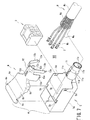
Fig. 1 is an exploded perspective view showing a shieldedconnector 1 according to a first preferred embodiment of the present invention; -
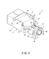
Fig. 2 is an external perspective view showing an assembled state of anouter conductor shell 4 comprised of two members; -
Fig. 3 is a view showing a section of the shieldedconnector 1 before a crimping process; -
Fig. 4A is a view showing an A-A section inFig. 3 , andFig. 4B is a view showing a B-B section inFig. 3 ; -
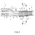
Fig. 5 is a view showing the section of the shieldedconnector 1 after the crimping process; -
Fig. 6A is a view showing a C-C section inFig. 5 , andFig. 6B is a view showing a D-D section inFig. 5 ; -
Fig. 7 is an exploded perspective view showing a shieldedconnector 10 according to a second preferred embodiment of the present invention; -
Fig. 8 is a view showing a section of the shieldedconnector 10 before a crimping process; -
Fig. 9A is a view showing an E-E section inFig. 8 , andFig. 9B is a view showing an F-F section inFig. 8 ; -
Fig. 10 is a view showing the section of the shieldedconnector 10 after the crimping process; and -
Fig. 11A is a view showing a G-G section inFig. 10, and Fig. 10B is a view showing an H-H section inFig. 10 . - A detailed description of preferred embodiments of a shielded connector according to the present invention will be given with reference to the accompanying drawings. The shielded connector according to the preferred embodiments of the present invention is used for a multi-contact shielded cable having a plurality of signal wires and is especially used for a shielded twisted-pair wire having six signal wires.
- First, a description of a shielded
connector 1 according to a first preferred embodiment of the present invention will be given with reference toFigs. 1 to 6 . - In the following descriptions, the side of the shielded conductor to which a corresponding connector (not shown) is fitted is referred to as the front side. As shown in
Fig. 1 , the shieldedconnector 1 to be connected to an end portion of a shielded twisted-pair wire W includesinner conductor terminals 2, aninner housing 3, and theouter conductor shell 4. - The
inner conductor terminals 2 are connected to signal conductors Wb of signal wires Wa of the shielded twisted-pair wire W to transmit high-frequency signals and have a so-called female terminal shape. Theinner housing 3 arranged to house theinner conductor terminals 2 provides an insulating state between theinner conductor terminals 2 and theouter conductor shell 4 and is made from a resin insulating member having a predetermined dielectric constant. Theinner conductor terminals 2 are inserted into theinner housing 3 from the back side to be secured. Theouter conductor shell 4 is connected to a shielded conductor Wd of the shielded twisted-pair wire W and covers theinner conductor terminals 2 to electromagnetically shield theinner conductor terminals 2. Theouter conductor shell 4 includes anouter conductor case 5 and anouter conductor cover 6 arranged to be assembled with theouter conductor case 5. - The
outer conductor case 5 has a substantially cylindrical shape and is prepared by bending a conductive plate material. Amain portion 5a of theouter conductor case 5 is arranged to house theinner housing 3 inside. On the top of themain portion 5a on the back side, anopening portion 5b is provided in order to allow theinner housing 3 to be easily housed in themain portion 5a. On side walls of theopening portion 5b on the front side,concave portions bent portions outer conductor cover 6 assembled as shown inFig. 2 are to be engaged. Further, on the side walls of theopening portion 5b on the back side,engagement portions flat portion 6d of theouter conductor cover 6 assembled as shown inFig. 2 so as to prevent theouter conductor cover 6 from being easily disengaged from theouter conductor case 5. - On the back side of the
main portion 5a of theouter conductor case 5, atubular connection portion 7 that opens upward and has an arc shape in cross section is provided. As shown inFig. 3 , thetubular connection portion 7 is covered with the shielded conductor Wd onto which a pair of shieldedconductor crimping portions sheath crimping portions outer conductor cover 6 are crimped. Thetubular connection portion 7 includes a large-diameter portion 7a onto which the shieldedconductor crimping portions diameter portion 7b onto which thesheath crimping portion diameter portion 7a of thetubular connection portion 7 preferably has an arc angle of 180 degrees or more in cross section, and in the first preferred embodiment, the arc angle is about 270 degrees as shown inFig. 4A . Owing to the large-diameter portion 7a having an arch shape in cross section, uniform compression stress is developed in the cross section during the crimping process, whereby the large-diameter portion 7a is not bent in its middle portion and shows high mechanical strength after being deformed by the crimping process. At the centers of upper ends of the large-diameter portion 7a,projection portions crimp portion 8 of theouter conductor cover 6 as shown inFig. 4A . Theprojection portions fitting spaces Fig. 6A ). Afitting hole 7d is provided in a bottom wall of the large-diameter portion 7a to run through the bottom wall.Projection portions conductor crimping portions outer conductor cover 6 as shown inFig. 4A , and theprojection portions fitting hole 7d during the crimping process (seeFig. 6A ). The shielded conductor Wd is fixed to the large-diameter portion 7a by the crimping of the shieldedconductor crimping portions diameter portion 7b of thetubular connection portion 7 has an arc angle of about 180 degrees in cross section as shown inFig. 4B . Owing to the small-diameter portion 7b having an arch shape in cross section, uniform compression stress is developed in the cross section during the crimping process, whereby the small-diameter portion 7b is not bent in its middle portion. As shown inFig. 3 , the small-diameter portion 7b is covered with the shielded conductor Wd and a sheath We. The shielded conductor Wd and the sheath We are fixed to the small-diameter portion 7b as shown inFig. 4B by the crimping of thesheath crimping portions Fig. 6B ). - The
outer conductor cover 6 has a roof shape and is formed by bending a conductive plate material in the same manner as theouter conductor case 5. Theouter conductor cover 6 includes acover portion 6a arranged to close theopening portion 5b of theouter conductor case 5 and thecrimp portion 8 provided to the back side of thecover portion 6a. Theopening portion 5b of theouter conductor case 5 is closed by theouter conductor cover 6, whereby deterioration of shielding performance is prevented. - The
cover portion 6a has a slantedportion 6b which is slanted backward from a middle portion of thecover portion 6a. On the both sides of a portion on the front side of the slantedportion 6b,bent portions bent portions concave portions outer conductor cover 6 is fit to theopening portion 5b of theouter conductor case 5, whereby downward movement of theouter conductor cover 6 is prevented. Further, the top surface of theflat portion 6d on the back side of the slantedportion 6b is engaged with theengagement portions outer conductor cover 6 is fit to theopening portion 5b of theouter conductor case 5 for preventing theouter conductor cover 6 from being easily disengaged from theouter conductor case 5. - On the back side of the
cover portion 6a of theouter conductor cover 6, thecrimp portion 8 is provided. Thecrimp portion 8 includes the shieldedconductor crimping portions sheath crimping portions - The shielded
conductor crimping portions crimp portion 8. At the centers of lower ends of the shieldedconductor crimping portions projection portions projection portions fitting hole 7d of the large-diameter portion 7a of theouter conductor cover 6 during the crimping process. Theprojection portions conductor crimping portions Fig. 6A when theprojection portions fitting hole 7d of the large-diameter portion 7a. Accordingly, theprojection portions fitting hole 7d of the large-diameter portion 7a. - A
concave portion 8d that extends inward is provided to the top wall of thecrimp portion 8 at a position corresponding to the shieldedconductor crimping portions spaces concave portion 8d, and theprojection portions diameter portion 7a of thetubular connection portion 7 and the shielded conductor Wd are inserted into thefitting spaces - The
sheath crimping portions crimp portion 8. The shielded conductor Wd and the sheath We are fixed to the small-diameter portion 7b of thetubular connection portion 7 during the crimping process of thesheath crimping portions sheath crimping portions sheath crimping portion 8b as shown inFig. 6B . - A process of connecting the shielded twisted-pair wire W to the shielded
connector 1 having the configuration described above includes steps of 1) exposing the signal conductors Wb and the shielded conductor Wd over predetermined lengths by stripping off a portion of the shielded twisted-pair wire W; 2) crimping crimp portions of theinner conductor terminals 2 onto the signal conductors Wb; 3) inserting theinner conductor terminals 2 into theinner housing 3; 4) housing theinner housing 3 in theouter conductor case 5 while covering thetubular connection portion 7 with the shielded conductor Wd; and 5) fitting theouter conductor cover 6 in theopening portion 5b of theouter conductor case 5 and simultaneously crimping thecrimp portion 8 of theouter conductor cover 6 and thetubular connection portion 7 onto the shielded conductor Wd and the sheath We. The.shieldedconnector 1 has the configuration in which thetubular connection portion 7 and the shieldedconductor crimping potions outer conductor shell 4, thetubular connection portion 7 having an arc shape in cross section and arranged to be inserted into the shielded conductor Wd which is exposed by stripping off a portion of the sheath We at the end portion of the shielded twisted-pair wire W, while the shieldedconductor crimping portions tubular connection portion 7 and arranged to be crimped onto the shielded conductor Wd in which thetubular connection portion 7 has been inserted. Accordingly, the shieldedconductor crimping portions tubular connection portion 7 without having an influence such as deformation of cross sections on the signal wires Wa in thetubular connection portion 7, whereby enhanced connection reliability between the shielded conductor Wd and the shieldedconductor crimping portions - Further, the
sheath crimping portions tubular connection portion 7 has been inserted are provided to theouter conductor shell 4. Accordingly, thesheath crimping portions tubular connection portion 7, whereby enhanced pull-out strength as well as improved connection reliability against bending stress of the shielded twisted-pair wire W are achieved. - Still further, the
outer conductor shell 4 is comprised of two members of theouter conductor case 5 to which thetubular connection portion 7 is provided and theouter conductor cover 6 to which thecrimp portion 8 is provided. Accordingly, theouter conductor shell 4 can be comprised of a limited number of members. In this case, owing to the large-diameter portion 7a of thetubular connection portion 7 having an arc angle of 180 degrees or more in cross section before the crimping process, the large-diameter portion 7a is deformed during the crimping process and becomes to have a substantially circle shape in cross section after the crimping process. Accordingly, the possibility that the signal wires Wa located in thetubular connection portion 7 may be influenced by deformation of cross sections is eliminated, and the shieldedconductor crimping portions diameter portion 7a on the shielded conductor Wd located on the large-diameter portion 7a of thetubular connection portion 7, whereby enhanced connection reliability among thetubular connection portion 7, the shielded conductor Wd and the shieldedconductor crimping portions - Yet further, the
fitting spaces conductor crimping portions tubular connection portion 7, and theprojection portions diameter portion 7a and the shielded conductor Wd are inserted into thefitting spaces conductor crimping portions diameter potion 7a on the shielded conductor Wd located on the large-diameter portion 7a, whereby enhanced pull-out strength of the shielded conductor Wd as well as improved connection reliability among thetubular connection portion 7, the shielded conductor Wd and the shieldedconductor crimping portions - Additionally, the
fitting spaces conductor crimping portions concave portion 8d that extends inward and is defined by a portion of the shieldedconductor crimping portions fitting spaces conductor crimping portions concave portion 8d is brought into contact with the shielded conductor Wd, whereby enhanced pull-out strength of the shielded conductor Wd as well as improved connection reliability are achieved. - In this case, the
fitting hole 7d is provided to the bottom wall of the large-diameter portion 7a of thetubular connection portion 7, and theprojection portions conductor crimping portions fitting hole 7d. Accordingly, the shieldedconductor crimping portions diameter portion 7a on the shielded conductor Wd located on the large-diameter portion 7a of thetubular connection portion 7, whereby enhanced pull-out strength of the shielded conductor Wd as well as improved convection reliability between the shielded conductor Wd and the shieldedconductor crimping portions conductor crimping portions connector 10 according to a second preferred embodiment of the present invention will be given with reference toFigs. 7 to 11 .Fig. 7 is an exploded perspective view showing the shieldedconnector 10 according to the second preferred embodiment of the present invention.Fig. 8 is a view showing a section of the shieldedconnector 10 before a crimping process.Fig. 9A is a view showing an E-E section inFig. 8 , andFig. 9B is a view showing an F-F section inFig. 8 .Fig. 10 is a view showing the section of the shieldedconnector 10 after the crimping process.Fig. 11A is a view showing a G-G section inFig. 10, and Fig. 10B is a view showing an H-H section inFig. 10 . - The same elements as the shielded
connector 1 according to the first preferred embodiment of the present invention are assigned the same reference numerals, descriptions thereof are omitted, and different respects are mainly described. - As shown in
Fig. 7 , atubular connection portion 11 having a circle shape in cross section is provided to the back side of themain portion 5a of theouter conductor case 5 of the shieldedconnector 10. As shown inFig. 8 , thetubular connection portion 11 is covered with the shielded conductor Wd onto which a pair of shieldedconductor crimping portions sheath crimping portions outer conductor cover 6 are crimped. Thetubular connection portion 11. includes a large-diameter portion 11a onto which the shieldedconductor crimping portions diameter portion 11b onto which thesheath crimping portion diameter portion 11a and the small-diameter portion 11b of thetubular connection portion 11 are made slightly larger than an inner diameter of the shielded conductor Wd so as to allow thetubular connection portion 11 to be easily inserted into the shielded conductor Wd. In a case where the shielded conductor Wd consists of a braided wire of a plurality of elemental wires, if the inner diameter of the shielded conductor Wd is enlarged, picks of the elemental wires are frayed. However, because the outer diameter of thetubular connection portion 11 having a circle shape in cross section is made substantially equal to the inner diameter of the shielded conductor Wd consisting of a braided wire, picks of the elemental wires are not frayed, whereby uniform crimping of the shieldedconductor crimping portions tubular connection portion 11, the shielded conductor Wd and the shieldedconductor crimping portions - The large-
diameter portion 11a of thetubular connection portion 11 has a substantially perfect circle shape in cross section as shown inFig. 9A . Owing to the large-diameter portion 11a having a substantially perfect circle shape in cross section, uniform compression stress is developed in the cross section during the crimping process, whereby the large-diameter portion 11a is not bent in its intermediate portion and shows high mechanical strength after being deformed by the crimping process. Aprojection portion 11c that projects upward is provided to a top wall of the large-diameter portion 11a. Afitting hole 12d is provided to a top wall of acrimp portion 12 of theouter conductor cover 6 as shown inFig. 9A , and theprojection portion 11c and the shielded conductor Wd are inserted into thefitting hole 12d during the crimping process (seeFig. 11A ). - A
fitting hole 11d is provided to a bottom wall of the large-diameter portion 11a to run through the bottom wall.Projection portions conductor crimping portions outer conductor cover 6 shown inFig. 9A and the shielded conductor Wd are inserted into thefitting hole 11d during the crimping process (seeFig. 11A ). During the crimping process, tips of theprojection portions projection portions fitting hole 11d of the large-diameter portion 11a. Accordingly, theprojection portions fitting hole 11d of the large-diameter potion 11a in a smoother manner than that described in the first preferred embodiment of the present invention in which theprojection portions conductor crimping portions fitting hole 7d of the large-diameter portion 7a, the inwardly-projectingprojection portions fitting hole 11d and the tips of theprojection portions fitting hole 11d while preventing the shielded conductor Wd going outward, whereby allowing the shielded conductor Wd at thefitting hole 11d to be held without fail. At this time, the shielded conductor Wd is fixed to the large-diameter portion 11a by the crimping of the shieldedconductor crimping portions - The small-
diameter portion 11b of thetubular connection portion 11 has a substantially perfect circle shape in cross section as shown inFig. 9B . Owing to the small-diameter portion 11b having a substantially perfect circle shape in cross section, uniform compression stress is developed in the cross section during the crimping process, whereby the small-diameter portion 11b is not bent in its intermediate portion and shows high mechanical strength after being deformed by the crimping process. The small-diameter portion 11b is covered with the shielded conductor Wd and the sheath We as shown inFig. 8 . - Further, a
fitting hole 11e is provided to the bottom wall of the small-diameter portion 11b to run through the bottom wall.Projection portions sheath crimping portions outer conductor cover 6 shown inFig. 9B and the shielded conductor Wd are inserted into thefitting hole 11e while theprojection portions Fig. 11B ). During the crimping process, the tips of theprojection portions projection portions fitting hole 11e of the small-diameter portion 11b. At this time, the shielded conductor Wd and the sheath We are fixed to the small-diameter portion 11b by the crimping of the shieldedconductor crimping portions Fig. 11B ). - The
crimp portion 12 is provided to the back side of thecover portion 6a of theouter conductor cover 6. Thecrimp portion 12 includes the shieldedconductor crimping portions sheath crimping portions - The shielded
conductor crimping portions crimp portion 12. At the centers of the lower ends of the shieldedconductor crimping portions projection portions projection portions fitting hole 11d of the large-diameter portion 11a of theouter conductor case 5 during the crimping process. - Further, the
fitting hole 12d is provided to the top wall of thecrimp portion 12 at a position corresponding to the shieldedconductor crimping portions projection portion 11c of the large-diameter portion 11a of thetubular connection portion 11 and the shielded conductor Wd are inserted into thefitting hole 12d during the crimping process. Thesheath crimping portions crimp portion 12. At the centers of the lower ends of thesheath crimping portions projection portions projection portions projection portions fitting hole 11e of the small-diameter portion 11b of theouter conductor cover 5 during the crimping process. Owing to this arrangement, the shielded conductor Wd and the sheath We are fixed to the small-diameter portion 11b of thetubular connection portion 11. - According to the shielded
connector 10 having the configuration in which thetubular connection portion 11 and the shieldedconductor crimping portions outer conductor shell 4, thetubular connection portion 11 having a circle shape in cross section and arranged to be inserted into the shielded conductor Wd which is exposed by stripping off the portion of the sheath We at the end portion of the shielded twisted-pair wire W, and the shieldedconductor crimping portions tubular connection portion 11 and arranged to be crimped onto the portion of the shielded conductor Wd in which thetubular convection portion 11 has been inserted. Accordingly, the shieldedconductor crimping portions tubular connection portion 11 on the shielded conductor Wd located on thetubular connection portion 11 without having an influence such as deformation of cross sections on the signal wires Wa in the shielded conductor Wd, whereby enhanced connection reliability between the shielded conductor Wd and the shieldedconductor crimping portions - Further, the
sheath crimping portions outer conductor shell 4 are crimped onto the end portion of the sheath We into which thetubular connection portion 11 has been inserted. Accordingly, thesheath crimping portions tubular connection portion 11 on the sheath We located on thetubular connection portion 7, whereby enhanced pull-out strength is also achieved. - Still further, the
outer conductor shell 4 is comprised of two members of theouter conductor case 5 and theouter conductor cover 6, theouter conductor case 5 including thetubular connection portion 11 and theouter conductor cover 6 including thecrimp portion 12. Accordingly, the number of members comprising theouter conductor shell 4 can be minimized. - In this case, the
projection portion 11c is provided to the top wall of the large-diameter portion 11a of thetubular connection portion 11 at the position opposed to the shieldedconductor crimping portions fitting hole 12d is provided to the shieldedconductor crimping portions projection portion 11c, and theprojection portion 11c and the shielded conductor Wd are inserted into thefitting hole 12d during the crimping process. Accordingly, enhanced pull-out strength of the shielded conductor Wd as well as improved connection reliability among thetubular connection portion 11, the shielded conductor Wd and the shieldedconductor crimping portions - Yet further, the
fitting hole 11d is provided to the bottom wall of the large-diameter portion 11a of thetubular connection portion 11, and theprojection portions conductor crimping portions fitting hole 11d. Accordingly, the shieldedconductor crimping portions tubular connection portion 11, whereby enhanced pull-out strength of the shielded conductor Wd as well as improved connection reliability between the shielded conductor Wd and the shieldedconductor crimping portions conductor crimping portions fitting hole 11e is provided to the small-diameter portion 11b of thetubular connection portion 11, and theprojection portions sheath crimping portions fitting hole 11e while theprojection portions sheath crimping portions tubular connection portion 11 and the sheath We, whereby thesheath crimping portions sheath crimping portions
Claims (12)
- A shielded connector to be connected to an end portion of a shielded cable (W) having a signal wire (Wb), a shielded conductor (Wd) arranged to cover the signal wire (Wb), and a sheath (We) arranged to cover the shielded conductor (Wd), the shielded connector comprising:an outer conductor shell (4) comprising:a tubular connection portion (7) having an arc shape in cross section and arranged to be inserted into an end portion of the shielded conductor (Wd) which is exposed by stripping off a portion of the sheath (We) at the end portion of the shielded cable (W) and into an end portion of the sheath (We);a pair of shielded conductor crimping portions (8a) opposed to the tubular connection portion (7) and arranged to be crimped onto the end portion of the shielded conductor (Wd) into which the tubular connection portion (7) has been inserted; anda pair of sheath crimping portions (8b) opposed to the tubular connection portion (7) and arranged to be crimped onto the end portion of the sheath (We) into which the tubular connection portion (7) has been inserted,wherein the tubular connection portion (7) has an arc angle of 180 degrees or more in cross section before a crimping process, andwherein the tubular connection portion (7) and the shielded conductor crimping portions (8a) together have a circle shape in cross section after the crimping process,characterized in thatthe outer conductor shell (4) further comprises fitting spaces (8e) provided to an inside of the shielded conductor crimping portions (8a) at positions opposed to the tubular connection portion (7); andupper ends of the tubular connection portion (7) and the shielded conductor (Wd) are inserted into the fitting spaces (8e) during the crimping process.
- The shielded connector according to claim 1,
wherein the outer conductor shell (4) further comprises projection portions (7c) each provided to the upper ends of the tubular connection portion (7). - The shielded connector according to claim 1 or 2,
wherein the fitting spaces (8e) of the shielded conductor crimping portions (8a) are provided by forming a concave portion (8d) that extends inward and is defined by a portion of the shielded conductor crimping portions (8a). - The shielded connector according to any one of claims 1 to 3,
wherein the outer conductor shell (4) further comprises a fitting hole (7d) provided to the bottom wall of the tubular connection portion (7), and
wherein lower ends of the shielded conductor crimping portions (8a) and the shielded conductor (Wd) are inserted into the fitting hole (7d), which prevents lifting caused by spring-back of the shielded conductor crimping portions (8a) after the crimping process. - The shielded connector according to claim 4,
wherein the outer conductor shell (4) further comprises projection portions (8c) each provided to the lower ends of the shielded conductor crimping portions (8a), and
wherein the projection portions (8c) and the shielded conductor (Wd) are inserted into the fitting hole (7d) provided to the bottom wall of the tubular connection portion (7) while tips of the projection portions (8c) come into contact with each other to bend the projection portions (8c) during the crimping process. - The shielded connector according to any one of claims 1 to 5,
wherein the outer conductor shell (4) further comprises a fitting hole (11e) provided to the bottom wall of the tubular connection portion (7), and
wherein lower ends of the sheath crimping portions (12b) and the shielded conductor (Wd) are inserted into the fitting hole of the tubular connection portion (7) while the sheath crimping portions (12b) are bent to break through the sheath (We), which prevents lifting caused by spring-back of the sheath crimping portions (12b) after the crimping process. - The shielded connector according to claim 6,
wherein the outer conductor shell (4) further comprises projection portions (12e) each provided to the lower ends of the sheath crimping portions (12b). - A shielded connector to be connected to an end portion of a shielded cable (W) having a signal wire (Wb), a shielded conductor (Wd) arranged to cover the signal wire (Wb), and a sheath (We) arranged to cover the shielded conductor (Wd), the shielded connector comprising:an outer conductor terminal comprising:a tubular connection portion (11) having a circle shape in cross section and arranged to be inserted into an end portion of the shielded conductor (Wd) which is exposed by stripping off a portion of the sheath (We) at the end portion of the shielded cable (W) and into an end portion of the sheath (We);a pair of shielded conductor crimping portions (12a) opposed to the tubular connection portion (11) and arranged to be crimped onto the end portion of the shielded conductor (Wd) into which the tubular connection portion (11) has been inserted; anda pair of sheath crimping portions (12b) opposed to the tubular connection portion (11) and arranged to be crimped onto the end portion of the sheath (We) into which the tubular connection portion (11) has been inserted,wherein an outer diameter of a portion of the tubular connection portion (11) onto which the shielded conductor crimping portions (12a) are crimped and an outer diameter of a portion of the tubular connection portion (11) onto which the sheath crimping portions (12b) are crimped are made equal to an inner diameter of the shielded conductor (Wd), andwherein the tubular connection portion (11) and the shielded conductor crimping portions (12a) together have a circle shape in cross section after the crimping processcharacterized in thatthe outer conductor shell (4) further comprises a projection portion (11c) provided to a top wall of the tubular connection portion (11) at a position opposed to the shielded conductor crimping portions (12a); anda fitting hole (12d) provided to the shielded conductor crimping portions (12a) opposed to the projection portion (11c); wherein the projection portion (11c) and the shielded conductor (Wd) are inserted into the fitting hole (12d) during the crimping process.
- The shielded connector according to claim 8, wherein the outer conductor shell (4) further comprises a fitting hole (11d) provided to the bottom wall of the tubular connection portion (11), and
wherein lower ends of the shielded conductor crimping portions (12a) and the shielded conductor (Wd) are inserted into the fitting hole (11d), which prevents lifting caused by spring-back of the shielded conductor crimping portions (12a) after the crimping process. - The shielded connector according to claim 8, wherein the outer conductor shell (4) further comprises projection portions (12c) provided to the lower ends of the shielded conductor crimping portions (12a), and
wherein the projection portions (12c) and the shielded conductor (Wd) are inserted into the fitting hole (11d) provided to the bottom wall of the tubular connection portion (11) while tips of the projection portions (12c) come into contact with each other to bend the projection portions (12c). - The shielded connector according to anyone of claims 8 to 10, wherein the outer conductor shell (4) further comprises a fitting hole (11e) provided to the bottom wall of the tubular connection portion (11), and
wherein lower ends of the sheath crimping portions (12b) and the shielded conductor (Wd) are inserted into the fitting hole (11e) while the sheath crimping portions (12b) are bent to break through the sheath (We), which prevents lifting caused by spring-back of the sheath crimping portions (12b) after the crimping process. - The shielded connector according to claim 11, wherein the outer conductor shell (4) further comprises projection portions (12e) provided to the lower ends of the sheath crimping portions (12b).
Applications Claiming Priority (2)
| Application Number | Priority Date | Filing Date | Title |
|---|---|---|---|
| JP2007200387A JP5008492B2 (en) | 2007-08-01 | 2007-08-01 | Shield connector |
| PCT/JP2008/063733 WO2009017186A1 (en) | 2007-08-01 | 2008-07-31 | Shield connector |
Publications (3)
| Publication Number | Publication Date |
|---|---|
| EP2178177A1 EP2178177A1 (en) | 2010-04-21 |
| EP2178177A4 EP2178177A4 (en) | 2012-04-04 |
| EP2178177B1 true EP2178177B1 (en) | 2015-04-08 |
Family
ID=40304414
Family Applications (1)
| Application Number | Title | Priority Date | Filing Date |
|---|---|---|---|
| EP08791962.7A Not-in-force EP2178177B1 (en) | 2007-08-01 | 2008-07-31 | Shield connector |
Country Status (4)
| Country | Link |
|---|---|
| US (2) | US7909647B2 (en) |
| EP (1) | EP2178177B1 (en) |
| JP (1) | JP5008492B2 (en) |
| WO (1) | WO2009017186A1 (en) |
Cited By (1)
| Publication number | Priority date | Publication date | Assignee | Title |
|---|---|---|---|---|
| DE112020003789B4 (en) | 2019-08-09 | 2026-03-19 | Autonetworks Technologies, Ltd. | Connector and connector device |
Families Citing this family (56)
| Publication number | Priority date | Publication date | Assignee | Title |
|---|---|---|---|---|
| JP2009099266A (en) * | 2007-10-12 | 2009-05-07 | Yazaki Corp | Shield terminal for coaxial cable |
| KR101538806B1 (en) * | 2009-03-16 | 2015-07-22 | 타이코에이엠피(유) | Shielded braided shell cover |
| CN102025084A (en) * | 2009-09-09 | 2011-04-20 | 富士康(昆山)电脑接插件有限公司 | Cable connector component |
| JP5606115B2 (en) * | 2010-03-23 | 2014-10-15 | 矢崎総業株式会社 | Connection structure of crimp terminal to wire |
| JP5066243B2 (en) * | 2010-06-08 | 2012-11-07 | ヒロセ電機株式会社 | Electrical connector and method of connecting twisted pair cable and electrical connector |
| JP5666242B2 (en) * | 2010-10-22 | 2015-02-12 | 矢崎総業株式会社 | Shield cover and shield structure |
| JP5743664B2 (en) * | 2011-04-13 | 2015-07-01 | 矢崎総業株式会社 | Shield connector |
| US9318849B2 (en) * | 2011-04-14 | 2016-04-19 | Yazaki Corporation | Shielded connector |
| DE102011107768B4 (en) * | 2011-07-15 | 2015-04-09 | Erni Production Gmbh & Co. Kg | Plug and method for its manufacture |
| JP2013069509A (en) * | 2011-09-21 | 2013-04-18 | Auto Network Gijutsu Kenkyusho:Kk | Harness |
| JP5896561B2 (en) * | 2012-06-12 | 2016-03-30 | 日本圧着端子製造株式会社 | connector |
| EP2875554B1 (en) * | 2012-07-23 | 2022-02-09 | Molex, LLC | Electrical harness connector system with differential pair connection link |
| US9490584B2 (en) * | 2013-07-19 | 2016-11-08 | Foxconn Interconnect Technology Limited | Flippable electrical connector |
| JP6036653B2 (en) * | 2013-11-12 | 2016-11-30 | 住友電装株式会社 | Shield connector |
| US9698501B2 (en) | 2013-12-10 | 2017-07-04 | Delphi Technologies Inc. | Electrical shield connector |
| US10211546B2 (en) * | 2013-12-10 | 2019-02-19 | Aptiv Technologies Limited | Electrical connection system for shielded wire cable |
| TWI607609B (en) * | 2014-03-24 | 2017-12-01 | 連展科技股份有限公司 | Electrical plug connector |
| ES2547260A1 (en) | 2014-04-01 | 2015-10-02 | Te Connectivity Amp España, S.L.U. | Screened telecommunications connector |
| WO2015164538A1 (en) | 2014-04-23 | 2015-10-29 | Tyco Electronics Corporation | Electrical connector with shield cap and shielded terminals |
| JP2016072067A (en) * | 2014-09-30 | 2016-05-09 | ホシデン株式会社 | connector |
| JP6429078B2 (en) * | 2015-01-29 | 2018-11-28 | 株式会社オートネットワーク技術研究所 | Shield connector |
| JP6437377B2 (en) * | 2015-04-22 | 2018-12-12 | ホシデン株式会社 | Shield case and connector provided with the same |
| EP3098905A1 (en) * | 2015-05-28 | 2016-11-30 | Delphi Technologies, Inc. | Electrical shield connector |
| JP6244332B2 (en) * | 2015-06-12 | 2017-12-06 | 矢崎総業株式会社 | Connector and connector manufacturing method |
| JP6443274B2 (en) * | 2015-09-09 | 2018-12-26 | 株式会社オートネットワーク技術研究所 | Communication connector and communication connector with wires |
| US9960504B2 (en) * | 2016-01-12 | 2018-05-01 | Yazaki Corporation | Shielded connector |
| JP6663814B2 (en) * | 2016-07-21 | 2020-03-13 | 日本航空電子工業株式会社 | Connector and wire harness |
| JP6729274B2 (en) * | 2016-10-12 | 2020-07-22 | 株式会社オートネットワーク技術研究所 | Connector structure |
| JP6509177B2 (en) * | 2016-10-12 | 2019-05-08 | 株式会社オートネットワーク技術研究所 | Connector structure |
| JP6745044B2 (en) * | 2017-02-03 | 2020-08-26 | 株式会社オートネットワーク技術研究所 | Shield terminal |
| JP6745043B2 (en) * | 2017-02-03 | 2020-08-26 | 株式会社オートネットワーク技術研究所 | Shield terminal |
| US10312605B2 (en) * | 2017-02-10 | 2019-06-04 | Autonetworks Technologies, Ltd. | Terminal-equipped wire |
| JP6642490B2 (en) * | 2017-03-08 | 2020-02-05 | 株式会社オートネットワーク技術研究所 | Shield terminal |
| JP6863164B2 (en) * | 2017-07-31 | 2021-04-21 | 株式会社オートネットワーク技術研究所 | Crimping structure of electric wire and shielded conductive path |
| EP3444907A1 (en) * | 2017-08-16 | 2019-02-20 | Rosenberger Hochfrequenztechnik GmbH & Co. KG | Connector assembly |
| DE102017122048A1 (en) * | 2017-09-22 | 2019-03-28 | Te Connectivity Germany Gmbh | Electrical contact device, electrical connection device, and method for assembling an electrical cable |
| JP6920980B2 (en) * | 2017-12-25 | 2021-08-18 | ヒロセ電機株式会社 | Shielded terminal unit and connector |
| JP6939529B2 (en) * | 2017-12-26 | 2021-09-22 | 住友電装株式会社 | Terminal bracket |
| JP6943175B2 (en) * | 2017-12-26 | 2021-09-29 | 住友電装株式会社 | Terminal fittings and connectors |
| JP6939531B2 (en) * | 2017-12-26 | 2021-09-22 | 住友電装株式会社 | Terminal bracket |
| DE102017131352B4 (en) * | 2017-12-27 | 2024-02-08 | Lisa Dräxlmaier GmbH | Cable connector and manufacturing process for an electrical connection |
| EP3588679B1 (en) * | 2018-06-29 | 2023-09-27 | TE Connectivity Germany GmbH | Crimp and method for producing a crimp |
| US10790619B2 (en) * | 2018-07-12 | 2020-09-29 | Cinch Connectors, Inc. | Shielded cable system for the shielding and protection against emi-leakage and impedance control |
| JP7047753B2 (en) * | 2018-12-28 | 2022-04-05 | 株式会社オートネットワーク技術研究所 | Connector and connector structure |
| EP3783751A1 (en) * | 2019-08-20 | 2021-02-24 | Aptiv Technologies Limited | Connector for automotive applications |
| EP3783755B1 (en) * | 2019-08-20 | 2022-11-02 | Aptiv Technologies Limited | Assembly comprising a connector and a cable |
| EP4560850A3 (en) | 2019-08-20 | 2025-08-13 | Aptiv Technologies AG | Connector for automotive applications and method of assembling thereof |
| EP3787132B1 (en) * | 2019-08-27 | 2024-06-26 | TE Connectivity Germany GmbH | Connector shielding with a circumferential retention element and method for manufacturing thereof |
| JP7031723B1 (en) * | 2020-12-08 | 2022-03-08 | Smk株式会社 | Manufacturing method of cable connector and cable connector |
| CN112736584B (en) * | 2020-12-30 | 2022-12-06 | 上海航天科工电器研究院有限公司 | Full-link shielding type high-speed cable assembly |
| JP2023077165A (en) * | 2021-11-24 | 2023-06-05 | 住友電装株式会社 | Connection structure of shield terminal and shield wire |
| CN118785982A (en) * | 2022-03-11 | 2024-10-15 | 赫斯曼汽车有限公司 | Shielding sleeve for plug connector |
| US12562531B2 (en) * | 2022-06-30 | 2026-02-24 | Apple Inc. | EMI shield for simplified connector manufacturing |
| JP2024068586A (en) | 2022-11-08 | 2024-05-20 | ヒロセ電機株式会社 | Connector device |
| JP2024068587A (en) | 2022-11-08 | 2024-05-20 | ヒロセ電機株式会社 | Connector, connector with cable and connector device |
| JP2025074572A (en) | 2023-10-30 | 2025-05-14 | ヒロセ電機株式会社 | Connectors and Connectors with Cables |
Family Cites Families (16)
| Publication number | Priority date | Publication date | Assignee | Title |
|---|---|---|---|---|
| US4337989A (en) * | 1980-05-28 | 1982-07-06 | Amp Incorporated | Electromagnetic shielded connector |
| EP0125760A1 (en) * | 1983-04-13 | 1984-11-21 | AMP INCORPORATED (a New Jersey corporation) | Connector plug having shielding enclosure |
| US4678121A (en) * | 1983-06-17 | 1987-07-07 | Amp Incorporated | Multiplane connector system |
| FR2654558B1 (en) * | 1989-11-10 | 1993-12-17 | Itt Composants Instruments | SHIELDED ELECTRICAL CONNECTOR ELEMENT. |
| JPH0718379A (en) | 1993-06-30 | 1995-01-20 | Aichi Steel Works Ltd | Steel for machine structure excellent in seizing resistance and fatigue strength |
| JP2569478Y2 (en) | 1993-09-02 | 1998-04-22 | 日本航空電子工業株式会社 | Connector with shield function |
| US5733146A (en) * | 1996-04-01 | 1998-03-31 | Block; Dale A. | Shield for modular electrical connector |
| US5725395A (en) * | 1996-08-12 | 1998-03-10 | Lee; Su-Lan Yang | Universal serial bus connector |
| JPH10270123A (en) | 1997-03-27 | 1998-10-09 | Harness Sogo Gijutsu Kenkyusho:Kk | Connector mounting structure for shielded wires |
| US6059607A (en) * | 1998-03-17 | 2000-05-09 | Molex Incorporated | Shielded electrical connector |
| JP3365549B2 (en) * | 1998-11-19 | 2003-01-14 | 住友電装株式会社 | Shield terminal |
| US6786781B2 (en) * | 2000-07-05 | 2004-09-07 | Tyco Electronics Amp, K.K. | Male contact |
| US6746277B2 (en) * | 2001-12-05 | 2004-06-08 | Tyco Electronics Corporation | Coaxial cable connector |
| JP2006244815A (en) * | 2005-03-02 | 2006-09-14 | Sumitomo Wiring Syst Ltd | Structure of barrel part |
| JP2006302824A (en) * | 2005-04-25 | 2006-11-02 | Auto Network Gijutsu Kenkyusho:Kk | Shield connector |
| JP4451386B2 (en) * | 2005-12-20 | 2010-04-14 | ヒロセ電機株式会社 | Electrical connector |
-
2007
- 2007-08-01 JP JP2007200387A patent/JP5008492B2/en not_active Expired - Fee Related
-
2008
- 2008-07-31 US US12/452,945 patent/US7909647B2/en not_active Expired - Fee Related
- 2008-07-31 WO PCT/JP2008/063733 patent/WO2009017186A1/en not_active Ceased
- 2008-07-31 EP EP08791962.7A patent/EP2178177B1/en not_active Not-in-force
-
2010
- 2010-12-07 US US12/926,738 patent/US8057258B2/en not_active Expired - Fee Related
Cited By (1)
| Publication number | Priority date | Publication date | Assignee | Title |
|---|---|---|---|---|
| DE112020003789B4 (en) | 2019-08-09 | 2026-03-19 | Autonetworks Technologies, Ltd. | Connector and connector device |
Also Published As
| Publication number | Publication date |
|---|---|
| US7909647B2 (en) | 2011-03-22 |
| US20100136832A1 (en) | 2010-06-03 |
| EP2178177A1 (en) | 2010-04-21 |
| JP2009037826A (en) | 2009-02-19 |
| WO2009017186A1 (en) | 2009-02-05 |
| JP5008492B2 (en) | 2012-08-22 |
| EP2178177A4 (en) | 2012-04-04 |
| US20110081803A1 (en) | 2011-04-07 |
| US8057258B2 (en) | 2011-11-15 |
Similar Documents
| Publication | Publication Date | Title |
|---|---|---|
| US7909647B2 (en) | Shielded connector | |
| CN101569063B (en) | shielded connector | |
| JP3946096B2 (en) | Shield connector | |
| EP0821438B1 (en) | Terminal fitting | |
| CN102891392B (en) | Shielded connector and method for assembling the shielded connector | |
| EP1003250A1 (en) | A shield connector, a set of shielded connectors and method for connecting a shielded connector with a shielded cable | |
| EP2603953A1 (en) | Electrical plug connector | |
| US20160365674A1 (en) | Connector and manufacturing method of connector | |
| JP4965226B2 (en) | Outer conductor terminal | |
| JP3738388B2 (en) | Coaxial connector | |
| US11710933B2 (en) | Terminal module, and connector | |
| US11804677B2 (en) | Electrical terminal module and connector with improved shielding features | |
| JP3998922B2 (en) | connector | |
| US12586959B2 (en) | Angled connector | |
| JP2021099931A (en) | Shield connector | |
| JP2009252356A (en) | Connector terminal | |
| JP7364374B2 (en) | shield connector | |
| US20250316930A1 (en) | Shield connector | |
| JP3344622B2 (en) | Shielded wire connector | |
| US20250316933A1 (en) | Shield connector | |
| JP5343589B2 (en) | Shield connector | |
| JP2025158081A (en) | Shielded Connector | |
| JP2025158082A (en) | Shielded Connector | |
| JP2025177916A (en) | Wire fixing structure | |
| JP2024153268A (en) | connector |
Legal Events
| Date | Code | Title | Description |
|---|---|---|---|
| PUAI | Public reference made under article 153(3) epc to a published international application that has entered the european phase |
Free format text: ORIGINAL CODE: 0009012 |
|
| 17P | Request for examination filed |
Effective date: 20100212 |
|
| AK | Designated contracting states |
Kind code of ref document: A1 Designated state(s): AT BE BG CH CY CZ DE DK EE ES FI FR GB GR HR HU IE IS IT LI LT LU LV MC MT NL NO PL PT RO SE SI SK TR |
|
| AX | Request for extension of the european patent |
Extension state: AL BA MK RS |
|
| DAX | Request for extension of the european patent (deleted) | ||
| A4 | Supplementary search report drawn up and despatched |
Effective date: 20120302 |
|
| RIC1 | Information provided on ipc code assigned before grant |
Ipc: H01R 13/655 20060101AFI20120228BHEP Ipc: H01R 24/38 20110101ALI20120228BHEP Ipc: H01R 9/03 20060101ALI20120228BHEP |
|
| GRAP | Despatch of communication of intention to grant a patent |
Free format text: ORIGINAL CODE: EPIDOSNIGR1 |
|
| INTG | Intention to grant announced |
Effective date: 20141022 |
|
| GRAS | Grant fee paid |
Free format text: ORIGINAL CODE: EPIDOSNIGR3 |
|
| GRAA | (expected) grant |
Free format text: ORIGINAL CODE: 0009210 |
|
| AK | Designated contracting states |
Kind code of ref document: B1 Designated state(s): AT BE BG CH CY CZ DE DK EE ES FI FR GB GR HR HU IE IS IT LI LT LU LV MC MT NL NO PL PT RO SE SI SK TR |
|
| REG | Reference to a national code |
Ref country code: GB Ref legal event code: FG4D |
|
| REG | Reference to a national code |
Ref country code: CH Ref legal event code: EP |
|
| REG | Reference to a national code |
Ref country code: IE Ref legal event code: FG4D |
|
| REG | Reference to a national code |
Ref country code: AT Ref legal event code: REF Ref document number: 721180 Country of ref document: AT Kind code of ref document: T Effective date: 20150515 |
|
| REG | Reference to a national code |
Ref country code: DE Ref legal event code: R096 Ref document number: 602008037587 Country of ref document: DE Effective date: 20150521 |
|
| REG | Reference to a national code |
Ref country code: AT Ref legal event code: MK05 Ref document number: 721180 Country of ref document: AT Kind code of ref document: T Effective date: 20150408 |
|
| REG | Reference to a national code |
Ref country code: NL Ref legal event code: VDEP Effective date: 20150408 |
|
| REG | Reference to a national code |
Ref country code: LT Ref legal event code: MG4D |
|
| PG25 | Lapsed in a contracting state [announced via postgrant information from national office to epo] |
Ref country code: NL Free format text: LAPSE BECAUSE OF FAILURE TO SUBMIT A TRANSLATION OF THE DESCRIPTION OR TO PAY THE FEE WITHIN THE PRESCRIBED TIME-LIMIT Effective date: 20150408 |
|
| PG25 | Lapsed in a contracting state [announced via postgrant information from national office to epo] |
Ref country code: NO Free format text: LAPSE BECAUSE OF FAILURE TO SUBMIT A TRANSLATION OF THE DESCRIPTION OR TO PAY THE FEE WITHIN THE PRESCRIBED TIME-LIMIT Effective date: 20150708 Ref country code: FI Free format text: LAPSE BECAUSE OF FAILURE TO SUBMIT A TRANSLATION OF THE DESCRIPTION OR TO PAY THE FEE WITHIN THE PRESCRIBED TIME-LIMIT Effective date: 20150408 Ref country code: PT Free format text: LAPSE BECAUSE OF FAILURE TO SUBMIT A TRANSLATION OF THE DESCRIPTION OR TO PAY THE FEE WITHIN THE PRESCRIBED TIME-LIMIT Effective date: 20150810 Ref country code: LT Free format text: LAPSE BECAUSE OF FAILURE TO SUBMIT A TRANSLATION OF THE DESCRIPTION OR TO PAY THE FEE WITHIN THE PRESCRIBED TIME-LIMIT Effective date: 20150408 Ref country code: ES Free format text: LAPSE BECAUSE OF FAILURE TO SUBMIT A TRANSLATION OF THE DESCRIPTION OR TO PAY THE FEE WITHIN THE PRESCRIBED TIME-LIMIT Effective date: 20150408 Ref country code: HR Free format text: LAPSE BECAUSE OF FAILURE TO SUBMIT A TRANSLATION OF THE DESCRIPTION OR TO PAY THE FEE WITHIN THE PRESCRIBED TIME-LIMIT Effective date: 20150408 |
|
| PG25 | Lapsed in a contracting state [announced via postgrant information from national office to epo] |
Ref country code: LV Free format text: LAPSE BECAUSE OF FAILURE TO SUBMIT A TRANSLATION OF THE DESCRIPTION OR TO PAY THE FEE WITHIN THE PRESCRIBED TIME-LIMIT Effective date: 20150408 Ref country code: IS Free format text: LAPSE BECAUSE OF FAILURE TO SUBMIT A TRANSLATION OF THE DESCRIPTION OR TO PAY THE FEE WITHIN THE PRESCRIBED TIME-LIMIT Effective date: 20150808 Ref country code: GR Free format text: LAPSE BECAUSE OF FAILURE TO SUBMIT A TRANSLATION OF THE DESCRIPTION OR TO PAY THE FEE WITHIN THE PRESCRIBED TIME-LIMIT Effective date: 20150709 Ref country code: AT Free format text: LAPSE BECAUSE OF FAILURE TO SUBMIT A TRANSLATION OF THE DESCRIPTION OR TO PAY THE FEE WITHIN THE PRESCRIBED TIME-LIMIT Effective date: 20150408 |
|
| REG | Reference to a national code |
Ref country code: DE Ref legal event code: R097 Ref document number: 602008037587 Country of ref document: DE |
|
| PG25 | Lapsed in a contracting state [announced via postgrant information from national office to epo] |
Ref country code: DK Free format text: LAPSE BECAUSE OF FAILURE TO SUBMIT A TRANSLATION OF THE DESCRIPTION OR TO PAY THE FEE WITHIN THE PRESCRIBED TIME-LIMIT Effective date: 20150408 Ref country code: EE Free format text: LAPSE BECAUSE OF FAILURE TO SUBMIT A TRANSLATION OF THE DESCRIPTION OR TO PAY THE FEE WITHIN THE PRESCRIBED TIME-LIMIT Effective date: 20150408 |
|
| PLBE | No opposition filed within time limit |
Free format text: ORIGINAL CODE: 0009261 |
|
| STAA | Information on the status of an ep patent application or granted ep patent |
Free format text: STATUS: NO OPPOSITION FILED WITHIN TIME LIMIT |
|
| PG25 | Lapsed in a contracting state [announced via postgrant information from national office to epo] |
Ref country code: MC Free format text: LAPSE BECAUSE OF FAILURE TO SUBMIT A TRANSLATION OF THE DESCRIPTION OR TO PAY THE FEE WITHIN THE PRESCRIBED TIME-LIMIT Effective date: 20150408 Ref country code: RO Free format text: LAPSE BECAUSE OF NON-PAYMENT OF DUE FEES Effective date: 20150408 Ref country code: PL Free format text: LAPSE BECAUSE OF FAILURE TO SUBMIT A TRANSLATION OF THE DESCRIPTION OR TO PAY THE FEE WITHIN THE PRESCRIBED TIME-LIMIT Effective date: 20150408 Ref country code: SK Free format text: LAPSE BECAUSE OF FAILURE TO SUBMIT A TRANSLATION OF THE DESCRIPTION OR TO PAY THE FEE WITHIN THE PRESCRIBED TIME-LIMIT Effective date: 20150408 Ref country code: CZ Free format text: LAPSE BECAUSE OF FAILURE TO SUBMIT A TRANSLATION OF THE DESCRIPTION OR TO PAY THE FEE WITHIN THE PRESCRIBED TIME-LIMIT Effective date: 20150408 |
|
| REG | Reference to a national code |
Ref country code: CH Ref legal event code: PL |
|
| 26N | No opposition filed |
Effective date: 20160111 |
|
| GBPC | Gb: european patent ceased through non-payment of renewal fee |
Effective date: 20150731 |
|
| PG25 | Lapsed in a contracting state [announced via postgrant information from national office to epo] |
Ref country code: LU Free format text: LAPSE BECAUSE OF FAILURE TO SUBMIT A TRANSLATION OF THE DESCRIPTION OR TO PAY THE FEE WITHIN THE PRESCRIBED TIME-LIMIT Effective date: 20150731 |
|
| PG25 | Lapsed in a contracting state [announced via postgrant information from national office to epo] |
Ref country code: CH Free format text: LAPSE BECAUSE OF NON-PAYMENT OF DUE FEES Effective date: 20150731 Ref country code: GB Free format text: LAPSE BECAUSE OF NON-PAYMENT OF DUE FEES Effective date: 20150731 Ref country code: LI Free format text: LAPSE BECAUSE OF NON-PAYMENT OF DUE FEES Effective date: 20150731 Ref country code: IT Free format text: LAPSE BECAUSE OF FAILURE TO SUBMIT A TRANSLATION OF THE DESCRIPTION OR TO PAY THE FEE WITHIN THE PRESCRIBED TIME-LIMIT Effective date: 20150408 |
|
| REG | Reference to a national code |
Ref country code: IE Ref legal event code: MM4A |
|
| PG25 | Lapsed in a contracting state [announced via postgrant information from national office to epo] |
Ref country code: SI Free format text: LAPSE BECAUSE OF FAILURE TO SUBMIT A TRANSLATION OF THE DESCRIPTION OR TO PAY THE FEE WITHIN THE PRESCRIBED TIME-LIMIT Effective date: 20150408 |
|
| REG | Reference to a national code |
Ref country code: FR Ref legal event code: PLFP Year of fee payment: 9 |
|
| PG25 | Lapsed in a contracting state [announced via postgrant information from national office to epo] |
Ref country code: IE Free format text: LAPSE BECAUSE OF NON-PAYMENT OF DUE FEES Effective date: 20150731 |
|
| PG25 | Lapsed in a contracting state [announced via postgrant information from national office to epo] |
Ref country code: BE Free format text: LAPSE BECAUSE OF FAILURE TO SUBMIT A TRANSLATION OF THE DESCRIPTION OR TO PAY THE FEE WITHIN THE PRESCRIBED TIME-LIMIT Effective date: 20150408 |
|
| PGFP | Annual fee paid to national office [announced via postgrant information from national office to epo] |
Ref country code: FR Payment date: 20160613 Year of fee payment: 9 |
|
| PGFP | Annual fee paid to national office [announced via postgrant information from national office to epo] |
Ref country code: DE Payment date: 20160726 Year of fee payment: 9 |
|
| PG25 | Lapsed in a contracting state [announced via postgrant information from national office to epo] |
Ref country code: MT Free format text: LAPSE BECAUSE OF FAILURE TO SUBMIT A TRANSLATION OF THE DESCRIPTION OR TO PAY THE FEE WITHIN THE PRESCRIBED TIME-LIMIT Effective date: 20150408 |
|
| PG25 | Lapsed in a contracting state [announced via postgrant information from national office to epo] |
Ref country code: BG Free format text: LAPSE BECAUSE OF FAILURE TO SUBMIT A TRANSLATION OF THE DESCRIPTION OR TO PAY THE FEE WITHIN THE PRESCRIBED TIME-LIMIT Effective date: 20150408 Ref country code: HU Free format text: LAPSE BECAUSE OF FAILURE TO SUBMIT A TRANSLATION OF THE DESCRIPTION OR TO PAY THE FEE WITHIN THE PRESCRIBED TIME-LIMIT; INVALID AB INITIO Effective date: 20080731 |
|
| PG25 | Lapsed in a contracting state [announced via postgrant information from national office to epo] |
Ref country code: CY Free format text: LAPSE BECAUSE OF FAILURE TO SUBMIT A TRANSLATION OF THE DESCRIPTION OR TO PAY THE FEE WITHIN THE PRESCRIBED TIME-LIMIT Effective date: 20150408 Ref country code: SE Free format text: LAPSE BECAUSE OF FAILURE TO SUBMIT A TRANSLATION OF THE DESCRIPTION OR TO PAY THE FEE WITHIN THE PRESCRIBED TIME-LIMIT Effective date: 20150408 |
|
| PG25 | Lapsed in a contracting state [announced via postgrant information from national office to epo] |
Ref country code: TR Free format text: LAPSE BECAUSE OF FAILURE TO SUBMIT A TRANSLATION OF THE DESCRIPTION OR TO PAY THE FEE WITHIN THE PRESCRIBED TIME-LIMIT Effective date: 20150408 |
|
| REG | Reference to a national code |
Ref country code: DE Ref legal event code: R119 Ref document number: 602008037587 Country of ref document: DE |
|
| REG | Reference to a national code |
Ref country code: FR Ref legal event code: ST Effective date: 20180330 |
|
| PG25 | Lapsed in a contracting state [announced via postgrant information from national office to epo] |
Ref country code: DE Free format text: LAPSE BECAUSE OF NON-PAYMENT OF DUE FEES Effective date: 20180201 |
|
| PG25 | Lapsed in a contracting state [announced via postgrant information from national office to epo] |
Ref country code: FR Free format text: LAPSE BECAUSE OF NON-PAYMENT OF DUE FEES Effective date: 20170731 |