EP2178158A1 - Wrist-wearable device comprising an antenna - Google Patents
Wrist-wearable device comprising an antenna Download PDFInfo
- Publication number
- EP2178158A1 EP2178158A1 EP08166960A EP08166960A EP2178158A1 EP 2178158 A1 EP2178158 A1 EP 2178158A1 EP 08166960 A EP08166960 A EP 08166960A EP 08166960 A EP08166960 A EP 08166960A EP 2178158 A1 EP2178158 A1 EP 2178158A1
- Authority
- EP
- European Patent Office
- Prior art keywords
- slot
- slot antenna
- case
- back cover
- antenna
- Prior art date
- Legal status (The legal status is an assumption and is not a legal conclusion. Google has not performed a legal analysis and makes no representation as to the accuracy of the status listed.)
- Granted
Links
- 239000004020 conductor Substances 0.000 claims abstract description 8
- 239000002184 metal Substances 0.000 claims description 15
- 238000012545 processing Methods 0.000 claims description 11
- 239000004033 plastic Substances 0.000 claims description 10
- 239000000463 material Substances 0.000 claims description 7
- 210000000707 wrist Anatomy 0.000 claims description 5
- 230000008878 coupling Effects 0.000 claims description 4
- 238000010168 coupling process Methods 0.000 claims description 4
- 238000005859 coupling reaction Methods 0.000 claims description 4
- 239000012777 electrically insulating material Substances 0.000 claims 1
- 230000005855 radiation Effects 0.000 description 11
- 238000013461 design Methods 0.000 description 3
- 238000004891 communication Methods 0.000 description 2
- 238000010586 diagram Methods 0.000 description 2
- 239000011521 glass Substances 0.000 description 2
- 210000004247 hand Anatomy 0.000 description 2
- 229920006362 Teflon® Polymers 0.000 description 1
- 230000005540 biological transmission Effects 0.000 description 1
- 229910010293 ceramic material Inorganic materials 0.000 description 1
- 238000010276 construction Methods 0.000 description 1
- 230000001419 dependent effect Effects 0.000 description 1
- 239000003989 dielectric material Substances 0.000 description 1
- 230000000694 effects Effects 0.000 description 1
- 238000005516 engineering process Methods 0.000 description 1
- 230000010354 integration Effects 0.000 description 1
- 238000012986 modification Methods 0.000 description 1
- 230000004048 modification Effects 0.000 description 1
- 239000011347 resin Substances 0.000 description 1
- 229920005989 resin Polymers 0.000 description 1
- 229910001220 stainless steel Inorganic materials 0.000 description 1
- 239000010935 stainless steel Substances 0.000 description 1
- 238000012546 transfer Methods 0.000 description 1
Images
Classifications
-
- H—ELECTRICITY
- H01—ELECTRIC ELEMENTS
- H01Q—ANTENNAS, i.e. RADIO AERIALS
- H01Q1/00—Details of, or arrangements associated with, antennas
- H01Q1/27—Adaptation for use in or on movable bodies
- H01Q1/273—Adaptation for carrying or wearing by persons or animals
-
- G—PHYSICS
- G01—MEASURING; TESTING
- G01S—RADIO DIRECTION-FINDING; RADIO NAVIGATION; DETERMINING DISTANCE OR VELOCITY BY USE OF RADIO WAVES; LOCATING OR PRESENCE-DETECTING BY USE OF THE REFLECTION OR RERADIATION OF RADIO WAVES; ANALOGOUS ARRANGEMENTS USING OTHER WAVES
- G01S13/00—Systems using the reflection or reradiation of radio waves, e.g. radar systems; Analogous systems using reflection or reradiation of waves whose nature or wavelength is irrelevant or unspecified
- G01S13/02—Systems using reflection of radio waves, e.g. primary radar systems; Analogous systems
- G01S13/50—Systems of measurement based on relative movement of target
- G01S13/58—Velocity or trajectory determination systems; Sense-of-movement determination systems
-
- G—PHYSICS
- G01—MEASURING; TESTING
- G01S—RADIO DIRECTION-FINDING; RADIO NAVIGATION; DETERMINING DISTANCE OR VELOCITY BY USE OF RADIO WAVES; LOCATING OR PRESENCE-DETECTING BY USE OF THE REFLECTION OR RERADIATION OF RADIO WAVES; ANALOGOUS ARRANGEMENTS USING OTHER WAVES
- G01S7/00—Details of systems according to groups G01S13/00, G01S15/00, G01S17/00
- G01S7/02—Details of systems according to groups G01S13/00, G01S15/00, G01S17/00 of systems according to group G01S13/00
- G01S7/03—Details of HF subsystems specially adapted therefor, e.g. common to transmitter and receiver
-
- H—ELECTRICITY
- H01—ELECTRIC ELEMENTS
- H01Q—ANTENNAS, i.e. RADIO AERIALS
- H01Q13/00—Waveguide horns or mouths; Slot antennas; Leaky-waveguide antennas; Equivalent structures causing radiation along the transmission path of a guided wave
- H01Q13/10—Resonant slot antennas
- H01Q13/18—Resonant slot antennas the slot being backed by, or formed in boundary wall of, a resonant cavity ; Open cavity antennas
Definitions
- the present invention is directed to a wrist-wearable device comprising an outer housing with a back cover, a front cover being parallel to said back cover, and a circumferential wall there between, said wall being substantially perpendicular to the back cover and to the front cover.
- the wrist-wearable device can for example be a wrist-top computer or a watch.
- the device further comprises at least one antenna which is able to send and to receive electromagnetic signals.
- the UK patent application published as GB 2431522 A discloses a wrist-wearable device having an outer housing with a slot being formed in the housing to provide a slot antenna.
- the longitudinal direction of the slot is parallel to a dial portion of the wrist-wearable device and is used for wireless communication with a communication network.
- Radar speedometers normally comprise a radar transmitter associated to a first antenna and a radar receiver associated to a second antenna.
- patch antennas or rod antennas are used for this kind of application.
- a drawback of these antenna technologies is that they are not well-suited for flush assembly on metallic watch cases.
- patch antennas gets easily detuned in the proximity of human tissue while rod antennas are apparently very sensitive to their surroundings and would thus be affected by the construction of the interior of a wrist-wearable device if integrated into such a device.
- the present invention aims at integrating a radar speedometer in a wrist-wearable device.
- this integration should be possible independently on the material chosen for the outer housing of the wrist-wearable device, i.e. as well for metal housings as for a plastic housing.
- a wrist-wearable device with at least one slot antenna comprising a case having electrically conducting inner surfaces and being fitted in the housing. Said case is limited on one side by an outer face lying substantially in a common plane with the wall of the housing. A slot extending substantially in a direction perpendicular to the back cover and to the front cover is formed in said outer face of the case, the inside of the case thereby forming a cavity of the slot antenna.
- the case of the slot antenna having electrically conducting inner surfaces serves as a cavity for the slot antenna.
- the invention can be used with a wrist-wearable device having a housing which is made of an electrically conducting material, in particular of metal, as well as with a device having a plastic housing.
- a slot antenna is very robust in terms of radiation characteristics against modifications of the interior of the watch case and is thus particularly suitable for radar speedometer applications as mentioned above. Furthermore, one can obtain a very large width of the main beam horizontal pattern.
- the device comprises two slot antennas, each of them having a case and a slot being formed in the outer face of said case, wherein the circumferential wall comprises an high impedance portion lying between the outer faces of the two cases .
- An embodiment with two slot antennas is particularly suitable for a radar speedometer application, as one antenna can be associated to a radar transmitter and the other one to a radar receiver. It should be noted, however, that it is also possible to use only one slot antenna. In this case it is necessary to provide additional radio components such as circulators on the transceiver side. Such a solution is slightly more costly than a solution using tow antennas, but may be preferable in certain cases for aesthetic and design reasons.
- the high impedance portion lying between the outer faces of the two cases reduces surface coupling between the two slots.
- the slot of the first antenna can be tilted with respect to the slot of the second antenna. Such an arrangement can be chosen for design reasons.
- the outer housing is at least partly made of a conducting material, in particular of metal, and the case of the slot antenna is electrically insulated from said outer housing.
- the outer housing is substantially made of a non-conducting material.
- the circumferential wall and the back cover can be made of a plastic material, while the front cover can either be made of glass or of a plastic material having a transparent portion.
- the device may advantageously comprise at least one electrically conducting surface on the circumferential wall.
- This electrically conducting surface will form a continuous antenna surface together with an adjacent outer surface of the case of the slot antenna.
- Such a bigger antenna surface can help to improve the radiation pattern.
- the device further comprises a shielding element lying in the plane of the back cover and protruding from the wall in an area below the slot antenna.
- a common shielding element may be provided in an area below the two slot antennas, or two separate shielding elements, one below each slot antenna, may be provided. The shielding tilts the main lobe directivity, and radiation is thus guided away from the user's wrist.
- the device further comprises a transmitter generating a radar signal and connected to a first slot antenna as well as a receiver and a signal processing unit connected to said receiver, the receiver being connected to the second slot antenna.
- a transmitter generating a radar signal and connected to a first slot antenna as well as a receiver and a signal processing unit connected to said receiver, the receiver being connected to the second slot antenna.
- the signal processing unit can be arranged to compute a speed of a person wearing the wrist-wearable device using signals captured by the second slot antenna.
- the device may furthermore comprise display means which are arranged to display a speed and/or a covered distance calculated by a signal processing unit.
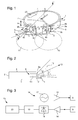
- Fig. 1 shows a perspective view of a wrist-wearable device, in the present case a wrist watch.
- the device comprises an outer housing 1 with a back cover 3 and a front cover 4, in the present case a glass for covering a dial with hands 6, 7 and an electronic display 20.
- a circumferential wall 2 lies between the back cover 3 and the front cover 4 and completes the housing 1.
- This wall 2 is shown as being substantially perpendicular to the front cover 4 and the back cover 3, but a toroidal or rounded shape or any other shape known in watch design is possible.
- the back cover 3 and the front cover 4 are shown as being circular, but they may also be oval or rectangular with or without rounded edges without departing from the scope of the present invention.
- the device shown in Fig. 1 comprises two slot antennas 8, 9, each of them comprising a block-shaped case 8b, 9b and a slot 8a, 9a.
- the cases 8b, 9b are either made of metal or of another material having a metallized inner surface and form a cavity for the slot antennas 8, 9.
- This cavity can be filled with a dielectric material having a high dielectric constant and a low dielectric loss such as Teflon®, a dielectric ceramic material or an appropriate resin.
- Cavity backed slot antennas are known in the art and their function principle will thus not be discussed here. It should be noted, however, that the minimum slot length which is required depends on the wavelength of the radar signal, the permittivity of the dielectric filling material and the shape of the slot.
- the slot length as much as possible so that the height e (cf. Fig. 1 ) of the wrist wearable device can be reduced.
- the shape of the slot may be adapted. It is possible, for example, to use a slot comprising a vertical main slot as shown in the figures and to provide it with additional slot structures which are perpendicular to this main slot, i.e. parallel to the front cover 4 and back cover 3.
- Both cases 8b, 9b have an outer face 8c, 9c which coincides with the circumferential wall 2 of the housing, the slots 8a, 9a being formed in said outer face, respectively.
- the outer faces 8c, 9c are metallized or made of metal and form an antenna surface together with adjacent metal plates 8d, 9d, as it will be explained below.
- the slots 8a, 9a are both oriented in a direction perpendicular to the back cover 3 and to the front cover 4 and are thus parallel to each other.
- one of the slots 8a, 9a may be slightly tilted with respect to the other slot 9a, 8a, and would in this case not be exactly perpendicular to back cover 3 and front cover 4.
- the slots 8a, 9a could be arranged such that the angle between the front cover 4 and the slots 8a, 9a is smaller than 90°. In this case the radiation is directed away from the user's wrist.
- the length of the slot 8a, 9a is determined by different factors, but it will normally be only slightly inferior to the height e of the circumferential wall 2 as shown in Fig. 2 .
- the housing 1 and in particular the wall 2 are made of a plastic material.
- the two cases 8b, 9b of the slot antennas 8, 9 are not directly adjacent, but are arranged at a certain distance d and are thus electrically insulated from each other.
- the invention is not limited to devices having plastic housings, however, and the housing 1 can be completely made of metal or comprise metallic parts.
- the circumferential wall 2 is made of an electrically conducting material, a high impedance portion will be provided in the wall 2 between the outer surfaces 8c, 9c. Such a high impedance portion avoids a coupling of the two antennas via surface waves.
- a simple solution would be a plastic insert or a plastic element applied to the surface of the circumferential wall 2 between the two slot antennas 8, 9.
- one can also use appropriate geometrical structures formed in the metal wall 2 such as photonic bandgap structures.
- two metal plates 8d, 9d are applied to the circumferential wall 2 on the left, respectively on the right, of each of the outer surfaces 8c, 9c of the antennas 8, 9.
- the electrically conducting surface of these metal plates 8d, 9d forms a continuous antenna surface together with the respective outer surface 8c, 9c of the slot antenna 8, 9, and the radiation pattern is improved thereby.
- the wall 2 itself is made of an electrically conducting material such as stainless steel or another metal. In such a case parts of the housing 1, in particular parts of the wall 2, can directly be part of the antenna surface.
- the horizontal radiation pattern is denoted with the reference numerals 10, 11 in Fig. 1 .
- the beam width ⁇ of the horizontal pattern (cf. Fig. 1 ) will be above 150°, preferably around 180° or higher, if the size of the outer surfaces 8c, 9c respectively the size of the metal plates 9c, 9d are chosen appropriately. Appropriate distance between the two slot antennas 8, 9, has to be selected to achieve the required value of antenna decoupling.
- the housing 1 is provided with a shielding element 5 lying in the plane of the back cover 3 and protruding from the wall 2 below the slot antennas 8, 9 and below the segment of wall 2 lying between them.
- a shielding element 5 lying in the plane of the back cover 3 and protruding from the wall 2 below the slot antennas 8, 9 and below the segment of wall 2 lying between them.
- the effects of this shielding become clear when looking at Fig. 2 which shows a cut along the axis II-II in Fig. 1 .
- the shielding 5 tilts the main beam directivity direction 13 with respect to the plane of the back cover 3, the tilting angle being denoted as ⁇ in Fig. 2 .
- the vertical radiation pattern obtained is shown in Fig. 2 . and denoted with the reference numeral 12.
- the beam width ⁇ of the vertical pattern 12 can reach up to
- Fig. 3 is a block diagram showing the electronic components necessary for the implementation of a radar speedometer in the device shown in Figs. 1 and 2 .
- a transmission chain 14 associated to a first slot antenna 8 comprises a radar transmitter 17 emitting a radar signal which is amplified by an amplifier 16. The amplified radar signal will be emitted via the slot antenna 8.
- the second slot antenna 9 is part of a reception chain 15 and is connected to a signal processing unit 19 via a receiver 18 and an amplifier 16' amplifying the signal received by the antenna 9.
- the signal processing unit 19 calculates a speed of the user wearing the device shown in Fig. 1 using an appropriate algorithm. Based on the speed, the signal processing unit may also calculate the distance covered by the user. The speed and/or the distance covered can then be shown by the display 20 which is integrated into the device.
Abstract
Description
- The present invention is directed to a wrist-wearable device comprising an outer housing with a back cover, a front cover being parallel to said back cover, and a circumferential wall there between, said wall being substantially perpendicular to the back cover and to the front cover. The wrist-wearable device can for example be a wrist-top computer or a watch. The device further comprises at least one antenna which is able to send and to receive electromagnetic signals.
- There exist various watches and wrist-top computers comprising an antenna for wireless data transfer into and out of the device.
- The UK patent application published as
GB 2431522 A - Various portable radar speedometers are also known from prior art. Radar speedometers normally comprise a radar transmitter associated to a first antenna and a radar receiver associated to a second antenna. Often, patch antennas or rod antennas are used for this kind of application. A drawback of these antenna technologies is that they are not well-suited for flush assembly on metallic watch cases. Furthermore, due to capacitive loading, patch antennas gets easily detuned in the proximity of human tissue while rod antennas are apparently very sensitive to their surroundings and would thus be affected by the construction of the interior of a wrist-wearable device if integrated into such a device.
- The present invention aims at integrating a radar speedometer in a wrist-wearable device. In particular, this integration should be possible independently on the material chosen for the outer housing of the wrist-wearable device, i.e. as well for metal housings as for a plastic housing.
- This aim is achieved by a wrist-wearable device according to claim 1 with at least one slot antenna comprising a case having electrically conducting inner surfaces and being fitted in the housing. Said case is limited on one side by an outer face lying substantially in a common plane with the wall of the housing. A slot extending substantially in a direction perpendicular to the back cover and to the front cover is formed in said outer face of the case, the inside of the case thereby forming a cavity of the slot antenna.
- The case of the slot antenna having electrically conducting inner surfaces serves as a cavity for the slot antenna. The invention can be used with a wrist-wearable device having a housing which is made of an electrically conducting material, in particular of metal, as well as with a device having a plastic housing. A slot antenna is very robust in terms of radiation characteristics against modifications of the interior of the watch case and is thus particularly suitable for radar speedometer applications as mentioned above. Furthermore, one can obtain a very large width of the main beam horizontal pattern.
- Preferred embodiments of the invention arise from the dependent claims and the following description.
- According to a preferred embodiment of the invention, the device comprises two slot antennas, each of them having a case and a slot being formed in the outer face of said case, wherein the circumferential wall comprises an high impedance portion lying between the outer faces of the two cases . An embodiment with two slot antennas is particularly suitable for a radar speedometer application, as one antenna can be associated to a radar transmitter and the other one to a radar receiver. It should be noted, however, that it is also possible to use only one slot antenna. In this case it is necessary to provide additional radio components such as circulators on the transceiver side. Such a solution is slightly more costly than a solution using tow antennas, but may be preferable in certain cases for aesthetic and design reasons.
- When two slot antennas are employed, the high impedance portion lying between the outer faces of the two cases reduces surface coupling between the two slots.
- The slot of the first antenna can be tilted with respect to the slot of the second antenna. Such an arrangement can be chosen for design reasons.
- According to a preferred embodiment, the outer housing is at least partly made of a conducting material, in particular of metal, and the case of the slot antenna is electrically insulated from said outer housing. The capacitive coupling between the watch case and the antenna or antennas which would normally occur with a metal housing can thereby be considerably reduced.
- According to an alternative embodiment of the present invention, the outer housing is substantially made of a non-conducting material. For example, the circumferential wall and the back cover can be made of a plastic material, while the front cover can either be made of glass or of a plastic material having a transparent portion.
- When such a plastic housing is used, the device may advantageously comprise at least one electrically conducting surface on the circumferential wall. This electrically conducting surface will form a continuous antenna surface together with an adjacent outer surface of the case of the slot antenna. Such a bigger antenna surface can help to improve the radiation pattern.
- According to a preferred embodiment of the invention, the device further comprises a shielding element lying in the plane of the back cover and protruding from the wall in an area below the slot antenna. When two slot antennas are provided, a common shielding element may be provided in an area below the two slot antennas, or two separate shielding elements, one below each slot antenna, may be provided. The shielding tilts the main lobe directivity, and radiation is thus guided away from the user's wrist.
- Preferably the device further comprises a transmitter generating a radar signal and connected to a first slot antenna as well as a receiver and a signal processing unit connected to said receiver, the receiver being connected to the second slot antenna.
- The signal processing unit can be arranged to compute a speed of a person wearing the wrist-wearable device using signals captured by the second slot antenna. The device may furthermore comprise display means which are arranged to display a speed and/or a covered distance calculated by a signal processing unit.
- The subject matter of the invention will be explained more in detail in the following description with reference to the drawings, wherein:
-
Fig. 1 is a perspective view of a device according to the invention; -
Fig. 2 is a cut view along the axis II-II inFig. 1 ; and -
Fig. 3 is a block diagram of the electronic components of the device shown inFigs 1 and 2 . - It will be appreciated that the following description is intended to refer to one specific embodiment of the invention which has been selected for illustration in the drawings but which is not intended to define or limit the invention, other than in the appended claims.
-
Fig. 1 shows a perspective view of a wrist-wearable device, in the present case a wrist watch. The device comprises an outer housing 1 with aback cover 3 and a front cover 4, in the present case a glass for covering a dial withhands 6, 7 and anelectronic display 20. Acircumferential wall 2 lies between theback cover 3 and the front cover 4 and completes the housing 1. Thiswall 2 is shown as being substantially perpendicular to the front cover 4 and theback cover 3, but a toroidal or rounded shape or any other shape known in watch design is possible. It should also be noted, that theback cover 3 and the front cover 4 are shown as being circular, but they may also be oval or rectangular with or without rounded edges without departing from the scope of the present invention. - The device shown in
Fig. 1 comprises twoslot antennas shaped case slot cases slot antennas Fig. 1 ) of the wrist wearable device can be reduced. To do so, the shape of the slot may be adapted. It is possible, for example, to use a slot comprising a vertical main slot as shown in the figures and to provide it with additional slot structures which are perpendicular to this main slot, i.e. parallel to the front cover 4 andback cover 3. - Both
cases outer face circumferential wall 2 of the housing, theslots outer faces adjacent metal plates Fig. 1 , theslots back cover 3 and to the front cover 4 and are thus parallel to each other. However, one of theslots other slot cover 3 and front cover 4. It is also possible to tilt the slot with respect to a vertical axis. For example, instead of being exactly perpendicular to theback cover 3 and front cover 4, theslots slots slot circumferential wall 2 as shown inFig. 2 . - In the embodiment shown in
Fig. 1 , the housing 1 and in particular thewall 2 are made of a plastic material. The twocases slot antennas circumferential wall 2 is made of an electrically conducting material, a high impedance portion will be provided in thewall 2 between theouter surfaces circumferential wall 2 between the twoslot antennas metal wall 2 such as photonic bandgap structures. - In the embodiment shown in
Figs. 1 and 2 , twometal plates circumferential wall 2 on the left, respectively on the right, of each of theouter surfaces antennas metal plates outer surface slot antenna circumferential wall 2 of the housing 1 of the device, if thewall 2 itself is made of an electrically conducting material such as stainless steel or another metal. In such a case parts of the housing 1, in particular parts of thewall 2, can directly be part of the antenna surface. - The horizontal radiation pattern is denoted with the
reference numerals Fig. 1 . The beam width α of the horizontal pattern (cf.Fig. 1 ) will be above 150°, preferably around 180° or higher, if the size of theouter surfaces metal plates slot antennas - The housing 1 is provided with a shielding element 5 lying in the plane of the
back cover 3 and protruding from thewall 2 below theslot antennas wall 2 lying between them. The effects of this shielding become clear when looking atFig. 2 which shows a cut along the axis II-II inFig. 1 . One sees that the shielding 5 tilts the mainbeam directivity direction 13 with respect to the plane of theback cover 3, the tilting angle being denoted as γ inFig. 2 . This protects the user from the radiation emitted and received by the device, and an attenuation of the signal in the tissue of the user wearing the device is avoided. The vertical radiation pattern obtained is shown inFig. 2 . and denoted with thereference numeral 12. The beam width β of thevertical pattern 12 can reach up to 90° or more. -
Fig. 3 is a block diagram showing the electronic components necessary for the implementation of a radar speedometer in the device shown inFigs. 1 and 2 . Atransmission chain 14 associated to afirst slot antenna 8 comprises aradar transmitter 17 emitting a radar signal which is amplified by anamplifier 16. The amplified radar signal will be emitted via theslot antenna 8. - The
second slot antenna 9 is part of areception chain 15 and is connected to asignal processing unit 19 via areceiver 18 and an amplifier 16' amplifying the signal received by theantenna 9. Thesignal processing unit 19 calculates a speed of the user wearing the device shown inFig. 1 using an appropriate algorithm. Based on the speed, the signal processing unit may also calculate the distance covered by the user. The speed and/or the distance covered can then be shown by thedisplay 20 which is integrated into the device. -
- 1
- housing
- 2
- circumferential wall
- 3
- back cover
- 4
- front cover
- 5
- shielding
- 6, 7
- hands
- 8, 9
- slot antenna
- 8a, 9a
- slot
- 8b, 9b
- case
- 8c, 9c
- outer surface of case
- 8d, 9d
- electrically conducting surface
- 10, 11
- horizontal radiation pattern
- 12
- vertical radiation pattern
- 13
- main beam directivity direction
- 14
- radar emission unit
- 15
- radar reception unit
- 16, 16'
- amplifier
- 17
- radar transmitter
- 18
- radar receiver
- 19
- signal processing unit
- 20
- display
- α
- horizontal beam width
- β
- vertical beam width
- γ
- radiation tilt angle
- e
- height housing
- d
- distance
Claims (13)
- Wrist-wearable device comprising an outer housing (1) with a back cover (3), a front cover (4) being parallel to said back cover (3), and a circumferential wall (2) there between, said wall being perpendicular to the back cover (3) and to the front cover (4), said device further comprising at least one slot antenna (8, 9) being able to send and to receive electromagnetic signals, said slot antenna (8, 9) comprising a case (8b, 9b) having electrically conducting inner surfaces and being fitted in the housing (1), said case (8b, 9b) being limited on one side by an outer face (8c, 9c) lying substantially in a common plane with the wall (2) of the housing (1), wherein a slot (8a, 9a) extending substantially in a direction perpendicular to the back cover (3) and the front cover (4) is formed in said outer face (8c, 9c) of the case (8b, 9b), the inside of the case thereby forming a cavity of the slot antenna (8, 9).
- Device according to claim 1, characterised in that it comprises two slot antennas (8, 9), each of them having a case (8b, 9b) and a slot (8a, 9a) being formed in the outer face (8c, 9c) of said case, wherein the circumferential wall (2) comprises an high impedance portion lying between the outer faces (8c, 9c) of the two cases (8b, 9b).
- Device according to claim 2, characterised in that the high impedance portion comprises a portion made of an electrically insulating material or a geometrical structure avoiding surface coupling.
- Device according to any of the preceding claims, characterised in that the case (8b, 9b) occupies substantially the complete space in a direction ranging from the back cover (3) to the front cover (4).
- Device according to any of the preceding claims, characterised in that it further comprises a shielding element (5) lying in the plane of the back cover (3) and protruding from the wall (2) in an area below the slot antenna (8, 9).
- Device according to any of the preceding claims, characterised in that the outer housing (1) is at least partly made of a conducting material, in particular of metal.
- Device according to any of claims 1 to 5, characterised in that the circumferential wall (2) and/or the back cover (3) are made of a non-conducting material, in particular of a plastic material.
- Device according to claim 7, characterised in that it comprises at least one electrically conducting surface (8d, 9d) on the circumferential wall (2), said electrically conducting surface (8d, 9d) forming a continuous antenna surface together with an adjacent outer surface (8c, 9c) of the slot antenna (8, 9).
- Device according to any of claims 2 to 8, characterised in that the slot (8a) of the first slot antenna (8) is tilted with respect to the slot (9a) of the second slot antenna (9).
- Device according to any of claims 2 to 9, characterised in that it further comprises a transmitter (17) generating a radar signal and connected to a first slot antenna (8) and a receiver (18) connected to the second slot antenna (9), the output of the receiver being transmitted to a signal processing unit (19).
- Device according to claim 10, characterised in that the signal processing unit (19) is arranged to compute a speed of and/or a distance covered by a person wearing the wrist wearable device using signals captured by the second slot antenna (9).
- Device according to any of the preceding claims, characterised in that it further comprises a signal processing unit (19) arranged for computing a speed of a user wearing the device and display means (20) arranged to display said speed.
- Device according claim 12, characterised in that the signal processing unit (19) is furthermore arranged for computing a distance covered by the user wearing the device, the display means (20) arranged to display said the speed and the distance covered.
Priority Applications (7)
| Application Number | Priority Date | Filing Date | Title |
|---|---|---|---|
| EP08166960A EP2178158B1 (en) | 2008-10-17 | 2008-10-17 | Wrist-wearable device comprising an antenna |
| AT08166960T ATE544195T1 (en) | 2008-10-17 | 2008-10-17 | WRIST-WEARED DEVICE HAVING AN ANTENNA |
| JP2011531481A JP5330522B2 (en) | 2008-10-17 | 2009-10-14 | Wrist wearing device with antenna |
| US13/121,575 US8833665B2 (en) | 2008-10-17 | 2009-10-14 | Wrist-wearable device comprising an antenna |
| CN200980141042.4A CN102187516B (en) | 2008-10-17 | 2009-10-14 | Wrist-wearable device comprising an antenna |
| PCT/EP2009/063428 WO2010043656A1 (en) | 2008-10-17 | 2009-10-14 | Wrist-wearable device comprising an antenna |
| HK12102274.9A HK1162085A1 (en) | 2008-10-17 | 2012-03-06 | Wrist-wearable device comprising an antenna |
Applications Claiming Priority (1)
| Application Number | Priority Date | Filing Date | Title |
|---|---|---|---|
| EP08166960A EP2178158B1 (en) | 2008-10-17 | 2008-10-17 | Wrist-wearable device comprising an antenna |
Publications (2)
| Publication Number | Publication Date |
|---|---|
| EP2178158A1 true EP2178158A1 (en) | 2010-04-21 |
| EP2178158B1 EP2178158B1 (en) | 2012-02-01 |
Family
ID=40456747
Family Applications (1)
| Application Number | Title | Priority Date | Filing Date |
|---|---|---|---|
| EP08166960A Active EP2178158B1 (en) | 2008-10-17 | 2008-10-17 | Wrist-wearable device comprising an antenna |
Country Status (7)
| Country | Link |
|---|---|
| US (1) | US8833665B2 (en) |
| EP (1) | EP2178158B1 (en) |
| JP (1) | JP5330522B2 (en) |
| CN (1) | CN102187516B (en) |
| AT (1) | ATE544195T1 (en) |
| HK (1) | HK1162085A1 (en) |
| WO (1) | WO2010043656A1 (en) |
Cited By (6)
| Publication number | Priority date | Publication date | Assignee | Title |
|---|---|---|---|---|
| GB2471753A (en) * | 2009-07-09 | 2011-01-12 | Apple Inc | Cavity-backed antenna for electronic devices |
| ITTV20120130A1 (en) * | 2012-07-13 | 2014-01-14 | I M Spa | "CASE OF DEVICE FOR INTERCONNECTION AND MULTIMEDIA COMMUNICATION THAT INTEGRATES AN ANTENNA" |
| WO2017003614A1 (en) * | 2015-06-27 | 2017-01-05 | Intel Corporation | Wearable antenna system |
| CN106486737A (en) * | 2015-09-02 | 2017-03-08 | 中兴通讯股份有限公司 | A kind of wrist-watch antenna and wrist-watch |
| CN110048219A (en) * | 2018-01-17 | 2019-07-23 | 惠州硕贝德无线科技股份有限公司 | A kind of electronic equipment of integrated ultra wide band 5G antenna |
| EP3602685A4 (en) * | 2017-03-27 | 2020-11-18 | INTEL Corporation | Antennas integrated into a printed circuit board |
Families Citing this family (11)
| Publication number | Priority date | Publication date | Assignee | Title |
|---|---|---|---|---|
| JP5896060B2 (en) * | 2010-11-12 | 2016-03-30 | セイコーエプソン株式会社 | Electronic clock with built-in antenna |
| CN102694230B (en) * | 2012-04-27 | 2016-12-14 | 深圳光启创新技术有限公司 | Watch antenna and manufacture method, real-time communication watch |
| US9196952B2 (en) * | 2013-03-15 | 2015-11-24 | Qualcomm Incorporated | Multipurpose antenna |
| US9601824B2 (en) | 2014-07-01 | 2017-03-21 | Microsoft Technology Licensing, Llc | Slot antenna integrated into a resonant cavity of an electronic device case |
| TWI575810B (en) * | 2015-07-20 | 2017-03-21 | 仁寶電腦工業股份有限公司 | Watch body with wireless transmission function and antenna structure thereof |
| US9985341B2 (en) | 2015-08-31 | 2018-05-29 | Microsoft Technology Licensing, Llc | Device antenna for multiband communication |
| KR102447757B1 (en) | 2015-11-06 | 2022-09-27 | 삼성전자주식회사 | Antenna and electronic device having the same |
| KR102567892B1 (en) | 2016-09-05 | 2023-08-17 | 삼성전자주식회사 | Electronic Device Involving Multi-Band Antenna |
| US10516199B2 (en) | 2017-01-26 | 2019-12-24 | North Inc. | Mobile device with slotted cavity antenna |
| US10305174B2 (en) | 2017-04-05 | 2019-05-28 | Futurewei Technologies, Inc. | Dual-polarized, omni-directional, and high-efficiency wearable antenna array |
| CN117154383A (en) * | 2022-05-24 | 2023-12-01 | 华为技术有限公司 | Electronic equipment |
Citations (4)
| Publication number | Priority date | Publication date | Assignee | Title |
|---|---|---|---|---|
| JPS63163185A (en) * | 1986-12-25 | 1988-07-06 | Mitsubishi Electric Corp | Radar |
| US5589840A (en) * | 1991-11-05 | 1996-12-31 | Seiko Epson Corporation | Wrist-type wireless instrument and antenna apparatus |
| US6307520B1 (en) * | 2000-07-25 | 2001-10-23 | International Business Machines Corporation | Boxed-in slot antenna with space-saving configuration |
| GB2431522A (en) | 2005-10-21 | 2007-04-25 | Suunto Oy | Slot antenna formed in the casing of a wrist-wearable device |
Family Cites Families (10)
| Publication number | Priority date | Publication date | Assignee | Title |
|---|---|---|---|---|
| JPS527907B2 (en) * | 1971-11-06 | 1977-03-05 | ||
| FR2644919B1 (en) * | 1989-03-21 | 1991-05-31 | Dassault Electronique | METHOD AND DEVICE FOR AIDING THE TRAFFIC OF LAND VEHICLES |
| JP3060840B2 (en) * | 1994-07-19 | 2000-07-10 | セイコーエプソン株式会社 | Wrist-mounted radio and antenna device |
| US5532705A (en) * | 1993-03-17 | 1996-07-02 | Seiko Epson Corporation | Wrist-mounted-type antenna device and apparatus having the antenna device |
| FR2739200B1 (en) * | 1995-09-26 | 1997-10-31 | Asulab Sa | WATCHMAKING PIECE WITH AN ANTENNA |
| DE10041922A1 (en) * | 2000-08-25 | 2002-03-07 | Armleder Thomas | Wrist watch has liquid crystal display or light emitting diode that is used to inform user, when radio signal is received by receiver which can receive two discreet frequencies of up to 433 MHz |
| CN2448026Y (en) * | 2000-09-19 | 2001-09-12 | 深圳市乐创意通讯技术有限公司 | Watch type pager |
| JP4317791B2 (en) * | 2004-06-25 | 2009-08-19 | 株式会社国際電気通信基礎技術研究所 | Array antenna |
| US7271774B2 (en) * | 2005-10-21 | 2007-09-18 | Suunto Oy | Electronic wearable device |
| US7778118B2 (en) * | 2007-08-28 | 2010-08-17 | Garmin Ltd. | Watch device having touch-bezel user interface |
-
2008
- 2008-10-17 EP EP08166960A patent/EP2178158B1/en active Active
- 2008-10-17 AT AT08166960T patent/ATE544195T1/en active
-
2009
- 2009-10-14 JP JP2011531481A patent/JP5330522B2/en active Active
- 2009-10-14 CN CN200980141042.4A patent/CN102187516B/en active Active
- 2009-10-14 US US13/121,575 patent/US8833665B2/en active Active
- 2009-10-14 WO PCT/EP2009/063428 patent/WO2010043656A1/en active Application Filing
-
2012
- 2012-03-06 HK HK12102274.9A patent/HK1162085A1/en unknown
Patent Citations (4)
| Publication number | Priority date | Publication date | Assignee | Title |
|---|---|---|---|---|
| JPS63163185A (en) * | 1986-12-25 | 1988-07-06 | Mitsubishi Electric Corp | Radar |
| US5589840A (en) * | 1991-11-05 | 1996-12-31 | Seiko Epson Corporation | Wrist-type wireless instrument and antenna apparatus |
| US6307520B1 (en) * | 2000-07-25 | 2001-10-23 | International Business Machines Corporation | Boxed-in slot antenna with space-saving configuration |
| GB2431522A (en) | 2005-10-21 | 2007-04-25 | Suunto Oy | Slot antenna formed in the casing of a wrist-wearable device |
Cited By (12)
| Publication number | Priority date | Publication date | Assignee | Title |
|---|---|---|---|---|
| GB2471753A (en) * | 2009-07-09 | 2011-01-12 | Apple Inc | Cavity-backed antenna for electronic devices |
| GB2471753B (en) * | 2009-07-09 | 2012-04-25 | Apple Inc | Cavity antennas for electronic devices |
| GB2485688A (en) * | 2009-07-09 | 2012-05-23 | Apple Inc | Cavity-backed antenna for electronic devices |
| GB2485688B (en) * | 2009-07-09 | 2013-07-31 | Apple Inc | Cavity antennas for electronic devices |
| US8896487B2 (en) | 2009-07-09 | 2014-11-25 | Apple Inc. | Cavity antennas for electronic devices |
| ITTV20120130A1 (en) * | 2012-07-13 | 2014-01-14 | I M Spa | "CASE OF DEVICE FOR INTERCONNECTION AND MULTIMEDIA COMMUNICATION THAT INTEGRATES AN ANTENNA" |
| WO2017003614A1 (en) * | 2015-06-27 | 2017-01-05 | Intel Corporation | Wearable antenna system |
| US9653786B2 (en) | 2015-06-27 | 2017-05-16 | Intel Corporation | Wearable antenna system |
| CN106486737A (en) * | 2015-09-02 | 2017-03-08 | 中兴通讯股份有限公司 | A kind of wrist-watch antenna and wrist-watch |
| EP3602685A4 (en) * | 2017-03-27 | 2020-11-18 | INTEL Corporation | Antennas integrated into a printed circuit board |
| US11276915B2 (en) | 2017-03-27 | 2022-03-15 | Intel Corporation | Antennas integrated into a printed circuit board |
| CN110048219A (en) * | 2018-01-17 | 2019-07-23 | 惠州硕贝德无线科技股份有限公司 | A kind of electronic equipment of integrated ultra wide band 5G antenna |
Also Published As
| Publication number | Publication date |
|---|---|
| HK1162085A1 (en) | 2012-08-17 |
| JP5330522B2 (en) | 2013-10-30 |
| EP2178158B1 (en) | 2012-02-01 |
| CN102187516B (en) | 2014-01-29 |
| WO2010043656A1 (en) | 2010-04-22 |
| JP2012517718A (en) | 2012-08-02 |
| US20110234461A1 (en) | 2011-09-29 |
| ATE544195T1 (en) | 2012-02-15 |
| CN102187516A (en) | 2011-09-14 |
| US8833665B2 (en) | 2014-09-16 |
Similar Documents
| Publication | Publication Date | Title |
|---|---|---|
| EP2178158B1 (en) | Wrist-wearable device comprising an antenna | |
| KR102028525B1 (en) | Combined Multiband Antenna for Wearable Wireless Devices | |
| EP3716403B1 (en) | Antenna module and electronic device | |
| US20160261032A1 (en) | Wearable electronic device | |
| WO2008033331A3 (en) | Antenna arrangement for an electronic device and an electronic device including same | |
| WO2009010724A1 (en) | Antennas | |
| KR20160041633A (en) | Radar device for vehicle | |
| EP3817137B1 (en) | Electronic device including an antenna structure | |
| EP3869773A1 (en) | Electronic device comprising antenna module | |
| CN108494430B (en) | Miniaturized millimeter wave radio frequency front end | |
| EP2077603A3 (en) | Dielectric leaky wave antenna | |
| CN111276792A (en) | Electronic device | |
| TWI653781B (en) | Mobile device | |
| CN108832292B (en) | Antenna and electronic equipment | |
| CN114079148A (en) | Antenna assembly and terminal equipment | |
| KR102647883B1 (en) | Electronic device comprising antenna module | |
| KR20190040995A (en) | An antenna structure for transmitting and / or receiving wireless electrical signals and an electronic device including a strap serving as a fixture of the device | |
| US11955731B2 (en) | Electronic device including multi-band antenna | |
| US10149636B2 (en) | Relay device for relaying radio frequency signals received from an antenna implanted within a patient's body to another device | |
| CN211670313U (en) | Millimeter wave antenna and millimeter wave antenna embedded into metal shell | |
| JP2006521054A (en) | Circuit device for mobile radio device | |
| US10348357B2 (en) | Single feed-in dual-brand antenna structure | |
| KR100835897B1 (en) | Antenna device | |
| CN112151954A (en) | Housing assembly, electronic device and dielectric constant adjusting method of housing assembly | |
| CN112542697B (en) | Dielectric lens, lens antenna, and electronic device |
Legal Events
| Date | Code | Title | Description |
|---|---|---|---|
| PUAI | Public reference made under article 153(3) epc to a published international application that has entered the european phase |
Free format text: ORIGINAL CODE: 0009012 |
|
| AK | Designated contracting states |
Kind code of ref document: A1 Designated state(s): AT BE BG CH CY CZ DE DK EE ES FI FR GB GR HR HU IE IS IT LI LT LU LV MC MT NL NO PL PT RO SE SI SK TR |
|
| AX | Request for extension of the european patent |
Extension state: AL BA MK RS |
|
| 17P | Request for examination filed |
Effective date: 20101021 |
|
| 17Q | First examination report despatched |
Effective date: 20101115 |
|
| AKX | Designation fees paid |
Designated state(s): AT BE BG CH CY CZ DE DK EE ES FI FR GB GR HR HU IE IS IT LI LT LU LV MC MT NL NO PL PT RO SE SI SK TR |
|
| GRAP | Despatch of communication of intention to grant a patent |
Free format text: ORIGINAL CODE: EPIDOSNIGR1 |
|
| GRAS | Grant fee paid |
Free format text: ORIGINAL CODE: EPIDOSNIGR3 |
|
| GRAA | (expected) grant |
Free format text: ORIGINAL CODE: 0009210 |
|
| AK | Designated contracting states |
Kind code of ref document: B1 Designated state(s): AT BE BG CH CY CZ DE DK EE ES FI FR GB GR HR HU IE IS IT LI LT LU LV MC MT NL NO PL PT RO SE SI SK TR |
|
| REG | Reference to a national code |
Ref country code: GB Ref legal event code: FG4D |
|
| REG | Reference to a national code |
Ref country code: CH Ref legal event code: NV Representative=s name: ICB INGENIEURS CONSEILS EN BREVETS SA Ref country code: CH Ref legal event code: EP Ref country code: AT Ref legal event code: REF Ref document number: 544195 Country of ref document: AT Kind code of ref document: T Effective date: 20120215 |
|
| REG | Reference to a national code |
Ref country code: DE Ref legal event code: R096 Ref document number: 602008013043 Country of ref document: DE Effective date: 20120329 |
|
| REG | Reference to a national code |
Ref country code: NL Ref legal event code: VDEP Effective date: 20120201 |
|
| LTIE | Lt: invalidation of european patent or patent extension |
Effective date: 20120201 |
|
| PG25 | Lapsed in a contracting state [announced via postgrant information from national office to epo] |
Ref country code: NO Free format text: LAPSE BECAUSE OF FAILURE TO SUBMIT A TRANSLATION OF THE DESCRIPTION OR TO PAY THE FEE WITHIN THE PRESCRIBED TIME-LIMIT Effective date: 20120501 Ref country code: IS Free format text: LAPSE BECAUSE OF FAILURE TO SUBMIT A TRANSLATION OF THE DESCRIPTION OR TO PAY THE FEE WITHIN THE PRESCRIBED TIME-LIMIT Effective date: 20120601 Ref country code: HR Free format text: LAPSE BECAUSE OF FAILURE TO SUBMIT A TRANSLATION OF THE DESCRIPTION OR TO PAY THE FEE WITHIN THE PRESCRIBED TIME-LIMIT Effective date: 20120201 Ref country code: NL Free format text: LAPSE BECAUSE OF FAILURE TO SUBMIT A TRANSLATION OF THE DESCRIPTION OR TO PAY THE FEE WITHIN THE PRESCRIBED TIME-LIMIT Effective date: 20120201 Ref country code: LT Free format text: LAPSE BECAUSE OF FAILURE TO SUBMIT A TRANSLATION OF THE DESCRIPTION OR TO PAY THE FEE WITHIN THE PRESCRIBED TIME-LIMIT Effective date: 20120201 |
|
| PG25 | Lapsed in a contracting state [announced via postgrant information from national office to epo] |
Ref country code: PT Free format text: LAPSE BECAUSE OF FAILURE TO SUBMIT A TRANSLATION OF THE DESCRIPTION OR TO PAY THE FEE WITHIN THE PRESCRIBED TIME-LIMIT Effective date: 20120601 Ref country code: PL Free format text: LAPSE BECAUSE OF FAILURE TO SUBMIT A TRANSLATION OF THE DESCRIPTION OR TO PAY THE FEE WITHIN THE PRESCRIBED TIME-LIMIT Effective date: 20120201 Ref country code: BE Free format text: LAPSE BECAUSE OF FAILURE TO SUBMIT A TRANSLATION OF THE DESCRIPTION OR TO PAY THE FEE WITHIN THE PRESCRIBED TIME-LIMIT Effective date: 20120201 Ref country code: GR Free format text: LAPSE BECAUSE OF FAILURE TO SUBMIT A TRANSLATION OF THE DESCRIPTION OR TO PAY THE FEE WITHIN THE PRESCRIBED TIME-LIMIT Effective date: 20120502 Ref country code: FI Free format text: LAPSE BECAUSE OF FAILURE TO SUBMIT A TRANSLATION OF THE DESCRIPTION OR TO PAY THE FEE WITHIN THE PRESCRIBED TIME-LIMIT Effective date: 20120201 Ref country code: LV Free format text: LAPSE BECAUSE OF FAILURE TO SUBMIT A TRANSLATION OF THE DESCRIPTION OR TO PAY THE FEE WITHIN THE PRESCRIBED TIME-LIMIT Effective date: 20120201 |
|
| REG | Reference to a national code |
Ref country code: AT Ref legal event code: MK05 Ref document number: 544195 Country of ref document: AT Kind code of ref document: T Effective date: 20120201 |
|
| PG25 | Lapsed in a contracting state [announced via postgrant information from national office to epo] |
Ref country code: CY Free format text: LAPSE BECAUSE OF FAILURE TO SUBMIT A TRANSLATION OF THE DESCRIPTION OR TO PAY THE FEE WITHIN THE PRESCRIBED TIME-LIMIT Effective date: 20120201 |
|
| PG25 | Lapsed in a contracting state [announced via postgrant information from national office to epo] |
Ref country code: CZ Free format text: LAPSE BECAUSE OF FAILURE TO SUBMIT A TRANSLATION OF THE DESCRIPTION OR TO PAY THE FEE WITHIN THE PRESCRIBED TIME-LIMIT Effective date: 20120201 Ref country code: RO Free format text: LAPSE BECAUSE OF FAILURE TO SUBMIT A TRANSLATION OF THE DESCRIPTION OR TO PAY THE FEE WITHIN THE PRESCRIBED TIME-LIMIT Effective date: 20120201 Ref country code: SI Free format text: LAPSE BECAUSE OF FAILURE TO SUBMIT A TRANSLATION OF THE DESCRIPTION OR TO PAY THE FEE WITHIN THE PRESCRIBED TIME-LIMIT Effective date: 20120201 Ref country code: EE Free format text: LAPSE BECAUSE OF FAILURE TO SUBMIT A TRANSLATION OF THE DESCRIPTION OR TO PAY THE FEE WITHIN THE PRESCRIBED TIME-LIMIT Effective date: 20120201 Ref country code: SE Free format text: LAPSE BECAUSE OF FAILURE TO SUBMIT A TRANSLATION OF THE DESCRIPTION OR TO PAY THE FEE WITHIN THE PRESCRIBED TIME-LIMIT Effective date: 20120201 Ref country code: DK Free format text: LAPSE BECAUSE OF FAILURE TO SUBMIT A TRANSLATION OF THE DESCRIPTION OR TO PAY THE FEE WITHIN THE PRESCRIBED TIME-LIMIT Effective date: 20120201 |
|
| PG25 | Lapsed in a contracting state [announced via postgrant information from national office to epo] |
Ref country code: IT Free format text: LAPSE BECAUSE OF FAILURE TO SUBMIT A TRANSLATION OF THE DESCRIPTION OR TO PAY THE FEE WITHIN THE PRESCRIBED TIME-LIMIT Effective date: 20120201 Ref country code: SK Free format text: LAPSE BECAUSE OF FAILURE TO SUBMIT A TRANSLATION OF THE DESCRIPTION OR TO PAY THE FEE WITHIN THE PRESCRIBED TIME-LIMIT Effective date: 20120201 |
|
| PLBE | No opposition filed within time limit |
Free format text: ORIGINAL CODE: 0009261 |
|
| STAA | Information on the status of an ep patent application or granted ep patent |
Free format text: STATUS: NO OPPOSITION FILED WITHIN TIME LIMIT |
|
| 26N | No opposition filed |
Effective date: 20121105 |
|
| PG25 | Lapsed in a contracting state [announced via postgrant information from national office to epo] |
Ref country code: AT Free format text: LAPSE BECAUSE OF FAILURE TO SUBMIT A TRANSLATION OF THE DESCRIPTION OR TO PAY THE FEE WITHIN THE PRESCRIBED TIME-LIMIT Effective date: 20120201 |
|
| REG | Reference to a national code |
Ref country code: DE Ref legal event code: R097 Ref document number: 602008013043 Country of ref document: DE Effective date: 20121105 |
|
| PG25 | Lapsed in a contracting state [announced via postgrant information from national office to epo] |
Ref country code: ES Free format text: LAPSE BECAUSE OF FAILURE TO SUBMIT A TRANSLATION OF THE DESCRIPTION OR TO PAY THE FEE WITHIN THE PRESCRIBED TIME-LIMIT Effective date: 20120512 |
|
| PG25 | Lapsed in a contracting state [announced via postgrant information from national office to epo] |
Ref country code: MC Free format text: LAPSE BECAUSE OF NON-PAYMENT OF DUE FEES Effective date: 20121031 |
|
| GBPC | Gb: european patent ceased through non-payment of renewal fee |
Effective date: 20121017 |
|
| REG | Reference to a national code |
Ref country code: IE Ref legal event code: MM4A |
|
| PG25 | Lapsed in a contracting state [announced via postgrant information from national office to epo] |
Ref country code: BG Free format text: LAPSE BECAUSE OF FAILURE TO SUBMIT A TRANSLATION OF THE DESCRIPTION OR TO PAY THE FEE WITHIN THE PRESCRIBED TIME-LIMIT Effective date: 20120501 Ref country code: GB Free format text: LAPSE BECAUSE OF NON-PAYMENT OF DUE FEES Effective date: 20121017 Ref country code: IE Free format text: LAPSE BECAUSE OF NON-PAYMENT OF DUE FEES Effective date: 20121017 |
|
| PG25 | Lapsed in a contracting state [announced via postgrant information from national office to epo] |
Ref country code: MT Free format text: LAPSE BECAUSE OF FAILURE TO SUBMIT A TRANSLATION OF THE DESCRIPTION OR TO PAY THE FEE WITHIN THE PRESCRIBED TIME-LIMIT Effective date: 20120201 |
|
| PG25 | Lapsed in a contracting state [announced via postgrant information from national office to epo] |
Ref country code: TR Free format text: LAPSE BECAUSE OF FAILURE TO SUBMIT A TRANSLATION OF THE DESCRIPTION OR TO PAY THE FEE WITHIN THE PRESCRIBED TIME-LIMIT Effective date: 20120201 |
|
| PG25 | Lapsed in a contracting state [announced via postgrant information from national office to epo] |
Ref country code: LU Free format text: LAPSE BECAUSE OF NON-PAYMENT OF DUE FEES Effective date: 20121017 |
|
| PG25 | Lapsed in a contracting state [announced via postgrant information from national office to epo] |
Ref country code: HU Free format text: LAPSE BECAUSE OF FAILURE TO SUBMIT A TRANSLATION OF THE DESCRIPTION OR TO PAY THE FEE WITHIN THE PRESCRIBED TIME-LIMIT Effective date: 20081017 |
|
| REG | Reference to a national code |
Ref country code: FR Ref legal event code: PLFP Year of fee payment: 9 |
|
| REG | Reference to a national code |
Ref country code: FR Ref legal event code: PLFP Year of fee payment: 10 |
|
| PGFP | Annual fee paid to national office [announced via postgrant information from national office to epo] |
Ref country code: FR Payment date: 20170921 Year of fee payment: 10 |
|
| PGFP | Annual fee paid to national office [announced via postgrant information from national office to epo] |
Ref country code: DE Payment date: 20170920 Year of fee payment: 10 |
|
| REG | Reference to a national code |
Ref country code: DE Ref legal event code: R119 Ref document number: 602008013043 Country of ref document: DE |
|
| PG25 | Lapsed in a contracting state [announced via postgrant information from national office to epo] |
Ref country code: DE Free format text: LAPSE BECAUSE OF NON-PAYMENT OF DUE FEES Effective date: 20190501 |
|
| PG25 | Lapsed in a contracting state [announced via postgrant information from national office to epo] |
Ref country code: FR Free format text: LAPSE BECAUSE OF NON-PAYMENT OF DUE FEES Effective date: 20181031 |
|
| P01 | Opt-out of the competence of the unified patent court (upc) registered |
Effective date: 20230701 |
|
| PGFP | Annual fee paid to national office [announced via postgrant information from national office to epo] |
Ref country code: CH Payment date: 20231102 Year of fee payment: 16 |