EP2178118A1 - Light emitting diode with energy recovery system - Google Patents
Light emitting diode with energy recovery system Download PDFInfo
- Publication number
- EP2178118A1 EP2178118A1 EP08166007A EP08166007A EP2178118A1 EP 2178118 A1 EP2178118 A1 EP 2178118A1 EP 08166007 A EP08166007 A EP 08166007A EP 08166007 A EP08166007 A EP 08166007A EP 2178118 A1 EP2178118 A1 EP 2178118A1
- Authority
- EP
- European Patent Office
- Prior art keywords
- light emitting
- electrical energy
- peltier element
- emitting diode
- heat
- Prior art date
- Legal status (The legal status is an assumption and is not a legal conclusion. Google has not performed a legal analysis and makes no representation as to the accuracy of the status listed.)
- Granted
Links
Images
Classifications
-
- H—ELECTRICITY
- H01—ELECTRIC ELEMENTS
- H01L—SEMICONDUCTOR DEVICES NOT COVERED BY CLASS H10
- H01L33/00—Semiconductor devices with at least one potential-jump barrier or surface barrier specially adapted for light emission; Processes or apparatus specially adapted for the manufacture or treatment thereof or of parts thereof; Details thereof
- H01L33/48—Semiconductor devices with at least one potential-jump barrier or surface barrier specially adapted for light emission; Processes or apparatus specially adapted for the manufacture or treatment thereof or of parts thereof; Details thereof characterised by the semiconductor body packages
- H01L33/64—Heat extraction or cooling elements
- H01L33/645—Heat extraction or cooling elements the elements being electrically controlled, e.g. Peltier elements
-
- F—MECHANICAL ENGINEERING; LIGHTING; HEATING; WEAPONS; BLASTING
- F21—LIGHTING
- F21K—NON-ELECTRIC LIGHT SOURCES USING LUMINESCENCE; LIGHT SOURCES USING ELECTROCHEMILUMINESCENCE; LIGHT SOURCES USING CHARGES OF COMBUSTIBLE MATERIAL; LIGHT SOURCES USING SEMICONDUCTOR DEVICES AS LIGHT-GENERATING ELEMENTS; LIGHT SOURCES NOT OTHERWISE PROVIDED FOR
- F21K9/00—Light sources using semiconductor devices as light-generating elements, e.g. using light-emitting diodes [LED] or lasers
-
- H—ELECTRICITY
- H01—ELECTRIC ELEMENTS
- H01L—SEMICONDUCTOR DEVICES NOT COVERED BY CLASS H10
- H01L2924/00—Indexing scheme for arrangements or methods for connecting or disconnecting semiconductor or solid-state bodies as covered by H01L24/00
- H01L2924/0001—Technical content checked by a classifier
- H01L2924/0002—Not covered by any one of groups H01L24/00, H01L24/00 and H01L2224/00
Definitions
- the invention relates to a light emitting diode (LED) which is electrically connected to an anode and a source.
- LED light emitting diode
- Such LEDs are used in a plurality of applications wherein light is to be emitted at low energy consumption.
- a typical application for such LEDs is the use for signalling a specific status like a stand-by mode, an activating mode or a failure of an electrical device.
- the LED is usually supplied with a small amount of energy to induce a small amount of light radiation from the LED sufficient to effect the signalling.
- LEDs are used to illuminate a field or region for a use like e.g. in a hand torch or a lamp installed in a vehicle like a car or an aircraft. In such appliances a high amount of energy is provided to the LED to induce a high amount of light radiation from said LED.
- the LED produces as a side effect a certain amount of heat when being provided with electrical energy. This heat must be removed from the LED which is usually achieved by heat radiation from the LED body or a coupling of the LED to a heat-dissipating element in order to avoid damage to the LED due to overheating.
- an LED according to the introductory portion wherein one of the anode and the source is thermally coupled to a first heat conductor, the heat conductor being thermally coupled to a first Peltier element to convert thermal energy transmitted from and generated in the light emitting crystal when the light emitting crystal is provided with electrical energy into electrical energy.
- the heat generated in an LED is not dissipated into ambient air but converted into electrical energy using a peltier element.
- a first peltier element is thermally coupled to the anode or the source of the LED.
- the other one of the anode and the source is thermally coupled to a second heat conductor, the second heat conductor being thermally coupled to a second Peltier element to convert thermal energy transmitted from and generated in the light emitting crystal when the light emitting crystal is provided with electrical energy into electrical energy.
- both anode and source are each thermally coupled to a separate peltier element which results in a high recovery rate of the thermal energy generated by the LED in operation and conversion of said thermal energy into electrical energy.
- first and second Peltier element are electrically coupled to an electrical storage device to store electrical energy generated in the Peltier element(s).
- the electrical energy generated in the Peltier element(s) can be stored for later use like e.g. for providing electrical energy to the LED in an emergency situation where the regular energy supplied to the LED has failed.
- the first and second Peltier element are electrically coupled to a source of electrical energy to provide energy to the Peltier element(s) in such a way that the Peltier element(s) is are cooled.
- the LED arrangement may be driven in a different mode of use wherein no electrical energy is converted in the Peltier elements from heat but rather electrical energy is provided to the Peltier elements to cool the Peltier elements to a low temperature.
- This preferred embodiment employs the specific characteristics of Peltier elements which are capable to be driven in two directions, namely to generate electrical energy from a heat gradient across the element or to create a heat difference when being provided with electrical energy.
- this is particularly useful in a situation where the LED is to be driven at a high light emission rate and thus a high amount of heat is generated by the LED which might potentially damage the LED after short time of use at such high light emission rate.
- the risk of being damaged can be significantly decreased and the lifetime of the LED thus increased by cooling down the one or both Peltier element(s) to a low temperature. Since the Peltier elements are thermally coupled to the LED, the LED will be cooled down to a significantly lower temperature by this and will thus be driven at a significantly lower temperature than in any other arrangement according to the prior art where the heat is dissipated into ambient air by passive heat dissipation.
- the LED arrangement comprises a control unit which is adapted to drive the light emitting diode in
- the LED arrangement according to the invention is capable to be switched between two distinct drive modes wherein the first drive mode provides an efficient light emission at a low rate with recovery of the heat dissipated by the LED and conversion of said heat into electrical energy and the second mode allows a very high rate of light emission by the LED and an active cooling of said LED via the Peltier element by driving said Peltier element with electrical energy.
- Such LED arrangement may be particularly useful in a situation where a permanent light emission is required for safety conditions in a standard operational mode but in specific situations of short time periods a high rate of light emission is required for e.g. illuminating a certain region or field.
- a second aspect of the invention is a method of driving a light emitting diode, comprising the step of providing electrical energy to an anode and a source electrically coupled to a light emitting crystal incorporated in the light emitting diode, wherein the steps of transferring heat from the light emitting crystal to a Peltier element and converting said heat in said Peltier element into electrical energy, wherein said electrical energy generated in the Peltier element is preferably transferred to an electrical energy storage or an electrical consumer.
- Said method allows an efficient driving of an LED and a recovery of the energy dissipated as heat energy from said LED.
- the method may be further improved in that the heat is transferred from the light emitting crystal to the Peltier element via electrical wires constituting the anode and/or the source.
- the heat is transferred from the light emitting crystal via an electrical wire constituting the anode coupling to a first Peltier element and via an electrical wire constituting the source coupling to a second Peltier element.
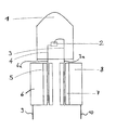
- the figure shows an LED body 1 incorporating a light emitting crystal 2 which is coupled to an anode 3 and a source 4.
- the anode 3 and the source 4 are constituted by electrical wires 3a, 4a which exit the LED body 1 at a bottom surface.
- the electrical wires are each connected to a first thermal coupling 5 and a second thermal coupling 7.
- the first thermal coupling 5 is thermally coupled to a first Peltier element 6 and the second thermal coupling 7 is thermally coupled to a second Peltier element 8.
- the Peltier elements are exposed to ambient air, the heat transferred via the electrical wires from the light emitting crystal to the Peltier element generate a heat gradient across the Peltier element.
- This heat difference generates electrical energy within the Peltier elements.
- This electrical energy may be provided to an electrical consumer or an electrical storage device.
- the Peltier elements are electrically connected to a respective wiring 9, 10.
- the Peltier elements may be provided with electrical energy. This will cool down the Peltier elements and will thus generate a significant temperature difference between the Peltier elements and the light emitting crystal of the LED. Thus, a significant amount of heat may be transferred from the light-emitting crystal 2 to the Peltier elements via heat conducting elements 5, 6. This will allow to drive the light emitting crystal at a very high light emission rate without the danger of damaging said light emitting crystal or any other parts of the LED for thermal reasons.
Abstract
Description
- The invention relates to a light emitting diode (LED) which is electrically connected to an anode and a source.
- Such LEDs are used in a plurality of applications wherein light is to be emitted at low energy consumption. A typical application for such LEDs is the use for signalling a specific status like a stand-by mode, an activating mode or a failure of an electrical device. In such applications, the LED is usually supplied with a small amount of energy to induce a small amount of light radiation from the LED sufficient to effect the signalling. In other applications LEDs are used to illuminate a field or region for a use like e.g. in a hand torch or a lamp installed in a vehicle like a car or an aircraft. In such appliances a high amount of energy is provided to the LED to induce a high amount of light radiation from said LED.
- In general, the LED produces as a side effect a certain amount of heat when being provided with electrical energy. This heat must be removed from the LED which is usually achieved by heat radiation from the LED body or a coupling of the LED to a heat-dissipating element in order to avoid damage to the LED due to overheating.
- It is an object of the invention to provide an LED which is capable to have a higher energy efficiency than LEDs according to the prior art. It is a further object of the invention to provide an LED which is capable to be driven with a small amount of energy in a first mode with high efficiency and which is capable to be driven in a second mode where the light emission from the LED is maximized.
- These and other objects of the invention are achieved by providing an LED according to the introductory portion wherein one of the anode and the source is thermally coupled to a first heat conductor, the heat conductor being thermally coupled to a first Peltier element to convert thermal energy transmitted from and generated in the light emitting crystal when the light emitting crystal is provided with electrical energy into electrical energy.
- According to the invention the heat generated in an LED is not dissipated into ambient air but converted into electrical energy using a peltier element. For this purpose, a first peltier element is thermally coupled to the anode or the source of the LED. By this arrangement, an LED arrangement is provided which is capable to recover at least a part of the energy which is converted into heat in the LED by converting said heat back into electrical energy and to thus provide a high efficiency of the whole arrangement. Thus, a partially self-sustaining LED arrangement is provided.
- According to a first preferred embodiment, the other one of the anode and the source is thermally coupled to a second heat conductor, the second heat conductor being thermally coupled to a second Peltier element to convert thermal energy transmitted from and generated in the light emitting crystal when the light emitting crystal is provided with electrical energy into electrical energy. By this, both anode and source are each thermally coupled to a separate peltier element which results in a high recovery rate of the thermal energy generated by the LED in operation and conversion of said thermal energy into electrical energy.
- It is further preferred that one or both of the first and second Peltier element are electrically coupled to an electrical storage device to store electrical energy generated in the Peltier element(s). By this, the electrical energy generated in the Peltier element(s) can be stored for later use like e.g. for providing electrical energy to the LED in an emergency situation where the regular energy supplied to the LED has failed.
- Further, it is preferred that one or both of the first and second Peltier element are electrically coupled to a source of electrical energy to provide energy to the Peltier element(s) in such a way that the Peltier element(s) is are cooled. According to this preferred embodiment, the LED arrangement may be driven in a different mode of use wherein no electrical energy is converted in the Peltier elements from heat but rather electrical energy is provided to the Peltier elements to cool the Peltier elements to a low temperature. This preferred embodiment employs the specific characteristics of Peltier elements which are capable to be driven in two directions, namely to generate electrical energy from a heat gradient across the element or to create a heat difference when being provided with electrical energy. In the LED arrangement according to the invention, this is particularly useful in a situation where the LED is to be driven at a high light emission rate and thus a high amount of heat is generated by the LED which might potentially damage the LED after short time of use at such high light emission rate. The risk of being damaged can be significantly decreased and the lifetime of the LED thus increased by cooling down the one or both Peltier element(s) to a low temperature. Since the Peltier elements are thermally coupled to the LED, the LED will be cooled down to a significantly lower temperature by this and will thus be driven at a significantly lower temperature than in any other arrangement according to the prior art where the heat is dissipated into ambient air by passive heat dissipation.
- According to a still further preferred embodiment, the LED arrangement comprises a control unit which is adapted to drive the light emitting diode in
- a first mode, wherein electrical energy of a first magnitude is provided to the light emitting diode and electrical energy converted from heat dissipated by the light emitting diode in the Peltier element(s) is received and provided to an electrical consumer or storage device, and in
- a second mode wherein electrical energy of a second magnitude is provided to the light emitting diode and electrical energy is provided to the the Peltier element(s) to cool the Peltier elements and to thus actively cool the light emitting diode via the Peltier elements,
- wherein the second magnitude of electrical energy is higher than the first magnitude.
- According to this preferred embodiment, the LED arrangement according to the invention is capable to be switched between two distinct drive modes wherein the first drive mode provides an efficient light emission at a low rate with recovery of the heat dissipated by the LED and conversion of said heat into electrical energy and the second mode allows a very high rate of light emission by the LED and an active cooling of said LED via the Peltier element by driving said Peltier element with electrical energy.
- Such LED arrangement may be particularly useful in a situation where a permanent light emission is required for safety conditions in a standard operational mode but in specific situations of short time periods a high rate of light emission is required for e.g. illuminating a certain region or field.
- A second aspect of the invention is a method of driving a light emitting diode, comprising the step of providing electrical energy to an anode and a source electrically coupled to a light emitting crystal incorporated in the light emitting diode, wherein the steps of transferring heat from the light emitting crystal to a Peltier element and converting said heat in said Peltier element into electrical energy, wherein said electrical energy generated in the Peltier element is preferably transferred to an electrical energy storage or an electrical consumer. Said method allows an efficient driving of an LED and a recovery of the energy dissipated as heat energy from said LED.
- The method may be further improved in that the heat is transferred from the light emitting crystal to the Peltier element via electrical wires constituting the anode and/or the source.
- Still further it is preferred that the heat is transferred from the light emitting crystal via an electrical wire constituting the anode coupling to a first Peltier element and via an electrical wire constituting the source coupling to a second Peltier element.
- Finally it is preferred that electrical energy is provided to at least one Peltier element and the Peltier element is cooled down by this electrical energy if the light radiation emitted by the light emitting crystal is increased.
- A preferred embodiment of the invention is described with reference to the figure.
- The figure shows an
LED body 1 incorporating alight emitting crystal 2 which is coupled to ananode 3 and a source 4. - The
anode 3 and the source 4 are constituted byelectrical wires 3a, 4a which exit theLED body 1 at a bottom surface. - The electrical wires are each connected to a first
thermal coupling 5 and a secondthermal coupling 7. - The first
thermal coupling 5 is thermally coupled to a firstPeltier element 6 and the secondthermal coupling 7 is thermally coupled to a secondPeltier element 8. - Since the Peltier elements are exposed to ambient air, the heat transferred via the electrical wires from the light emitting crystal to the Peltier element generate a heat gradient across the Peltier element.
- This heat difference generates electrical energy within the Peltier elements. This electrical energy may be provided to an electrical consumer or an electrical storage device. For this purpose, the Peltier elements are electrically connected to a
respective wiring 9, 10. - Vice versa, via said wiring 9, 10 connected to the Peltier element the Peltier elements may be provided with electrical energy. This will cool down the Peltier elements and will thus generate a significant temperature difference between the Peltier elements and the light emitting crystal of the LED. Thus, a significant amount of heat may be transferred from the light-emitting
crystal 2 to the Peltier elements viaheat conducting elements
Claims (9)
- Light emitting diode arrangement, comprising a light emitting diode with a light emitting crystal, electrically connected to an anode and a source,
characterized in that one of the anode and the source is thermally coupled to a first heat conductor, the heat conductor being thermally coupled to a first Peltier element to convert thermal energy transmitted from and generated in the light emitting crystal when the light emitting crystal is provided with electrical energy into electrical energy. - Light emitting diode arrangement according to claim 1, wherein the other one of the anode and the source is thermally coupled to a second heat conductor, the second heat dissipating body being thermally coupled to a second Peltier element to convert thermal energy transmitted from and generated in the light emitting crystal when the light emitting crystal is provided with electrical energy into electrical energy.
- Light emitting diode arrangement according to claim 1 or 2, wherein one or both of the first and second Peltier element are electrically coupled to an electrical storage device to store electrical energy generated in the Peltier element(s).
- Light emitting diode arrangement according to any of the preceding claims, wherein one or both of the first and second Peltier element are electrically coupled to a source of electrical energy to provide energy to the Peltier element(s) in such a way that the Peltier element(s) is are cooled.
- Light emitting diode arrangement according to any of the preceding claims, further comprising a control unit adapted to drive the light emitting diode in- a first mode, wherein electrical energy of a first level is provided to the light emitting diode and electrical energy converted from heat dissipated by the light emitting diode in the Peltier element(s) is received and provided to an electrical consumer or storage device, and in- a second mode wherein electrical energy of a second level is provided to the light emitting diode and electrical energy is provided to the Peltier element(s) to cool the Peltier elements and to thus actively cool the light emitting diode via the Peltier elements,- wherein the second level of electrical energy is higher than the first level.
- A method of driving a light emitting diode, comprising the step of providing electrical energy to an anode and a source electrically coupled to a light emitting crystal incorporated in the light emitting diode,
characterized by the steps of transferring heat from the light emitting crystal to a Peltier element and converting said heat in said Peltier element into electrical energy, wherein said electrical energy generated in the Peltier element is preferably transferred to an electrical energy storage or an electrical consumer. - A method according to claim 6, wherein the heat is transferred from the light emitting crystal to the Peltier element via electrical wires constituting the anode and/or the source.
- A method according to claim 6 or 7, wherein the heat is transferred from the light emitting crystal via an electrical wire constituting the anode coupling to a first Peltier element and via an electrical wire constituting the source coupling to a second Peltier element.
- A method according to any of the claims 6 to 8, wherein electrical energy is provided to at least one Peltier element and the Peltier element is cooled down by this electrical energy if the light radiation emitted by the light emitting crystal is increased.
Priority Applications (1)
| Application Number | Priority Date | Filing Date | Title |
|---|---|---|---|
| EP08166007.8A EP2178118B1 (en) | 2008-10-07 | 2008-10-07 | Light emitting diode with energy recovery system |
Applications Claiming Priority (1)
| Application Number | Priority Date | Filing Date | Title |
|---|---|---|---|
| EP08166007.8A EP2178118B1 (en) | 2008-10-07 | 2008-10-07 | Light emitting diode with energy recovery system |
Publications (2)
| Publication Number | Publication Date |
|---|---|
| EP2178118A1 true EP2178118A1 (en) | 2010-04-21 |
| EP2178118B1 EP2178118B1 (en) | 2015-08-26 |
Family
ID=40456190
Family Applications (1)
| Application Number | Title | Priority Date | Filing Date |
|---|---|---|---|
| EP08166007.8A Expired - Fee Related EP2178118B1 (en) | 2008-10-07 | 2008-10-07 | Light emitting diode with energy recovery system |
Country Status (1)
| Country | Link |
|---|---|
| EP (1) | EP2178118B1 (en) |
Cited By (2)
| Publication number | Priority date | Publication date | Assignee | Title |
|---|---|---|---|---|
| EP2615030A1 (en) | 2012-01-16 | 2013-07-17 | Intertechnique | Passenger service unit with emergency oxygen supply and reading light |
| WO2015021633A1 (en) * | 2013-08-15 | 2015-02-19 | Wang Huafeng | Flashlight with thermoelectric effect |
Citations (6)
| Publication number | Priority date | Publication date | Assignee | Title |
|---|---|---|---|---|
| DE2333119A1 (en) * | 1973-06-29 | 1975-01-23 | Licentia Gmbh | Semiconductor laser with Peltier element heat sink - has Peltier elements between semiconductor body and heat sink block |
| US20040155251A1 (en) * | 2003-02-07 | 2004-08-12 | Vladimir Abramov | Peltier cooler integrated with electronic device(s) |
| JP2004342557A (en) * | 2003-05-19 | 2004-12-02 | Seiko Epson Corp | Lighting system and projection type display device |
| US20050088588A1 (en) * | 2003-10-27 | 2005-04-28 | Lg. Philips Lcd Co., Ltd. | Liquid crystal display device including backlight unit |
| JP2006059930A (en) * | 2004-08-18 | 2006-03-02 | Matsushita Electric Works Ltd | Led illuminator |
| JP2007036166A (en) * | 2005-07-27 | 2007-02-08 | Advanced Material Japan Corp | Long persistence light |
Family Cites Families (6)
| Publication number | Priority date | Publication date | Assignee | Title |
|---|---|---|---|---|
| JP2001308395A (en) * | 2000-04-21 | 2001-11-02 | Matsushita Electric Ind Co Ltd | Heat energy regenerating system for electronic apparatus |
| KR100671851B1 (en) * | 2005-04-27 | 2007-01-19 | 주식회사 미광전자 | Energy-saving led |
| JP2007019058A (en) * | 2005-07-05 | 2007-01-25 | Yamaha Corp | Light source equipment |
| WO2007056706A2 (en) * | 2005-11-04 | 2007-05-18 | Universal Media Systems, Inc. | Dynamic heat sink for light emitting diodes |
| JP4796868B2 (en) * | 2006-03-01 | 2011-10-19 | エヌイーシーコンピュータテクノ株式会社 | ELECTRONIC CIRCUIT STRUCTURE, ELECTRONIC DEVICE EQUIPPED WITH THE STRUCTURE, THERMAL ELECTRIC POWER GENERATION METHOD, SUPPORT POWER GENERATION METHOD, AND SEMICONDUCTOR BARE CHIP |
| WO2010010520A2 (en) * | 2008-07-23 | 2010-01-28 | Nxp B.V. | Integrated seebeck device |
-
2008
- 2008-10-07 EP EP08166007.8A patent/EP2178118B1/en not_active Expired - Fee Related
Patent Citations (6)
| Publication number | Priority date | Publication date | Assignee | Title |
|---|---|---|---|---|
| DE2333119A1 (en) * | 1973-06-29 | 1975-01-23 | Licentia Gmbh | Semiconductor laser with Peltier element heat sink - has Peltier elements between semiconductor body and heat sink block |
| US20040155251A1 (en) * | 2003-02-07 | 2004-08-12 | Vladimir Abramov | Peltier cooler integrated with electronic device(s) |
| JP2004342557A (en) * | 2003-05-19 | 2004-12-02 | Seiko Epson Corp | Lighting system and projection type display device |
| US20050088588A1 (en) * | 2003-10-27 | 2005-04-28 | Lg. Philips Lcd Co., Ltd. | Liquid crystal display device including backlight unit |
| JP2006059930A (en) * | 2004-08-18 | 2006-03-02 | Matsushita Electric Works Ltd | Led illuminator |
| JP2007036166A (en) * | 2005-07-27 | 2007-02-08 | Advanced Material Japan Corp | Long persistence light |
Cited By (4)
| Publication number | Priority date | Publication date | Assignee | Title |
|---|---|---|---|---|
| EP2615030A1 (en) | 2012-01-16 | 2013-07-17 | Intertechnique | Passenger service unit with emergency oxygen supply and reading light |
| WO2013107769A1 (en) | 2012-01-16 | 2013-07-25 | Intertechnique | Passenger service unit with emergency oxygen supply and reading light |
| US8978644B2 (en) | 2012-01-16 | 2015-03-17 | Zodiac Aerotechnics | Passenger service unit with emergency oxygen supply and reading light |
| WO2015021633A1 (en) * | 2013-08-15 | 2015-02-19 | Wang Huafeng | Flashlight with thermoelectric effect |
Also Published As
| Publication number | Publication date |
|---|---|
| EP2178118B1 (en) | 2015-08-26 |
Similar Documents
| Publication | Publication Date | Title |
|---|---|---|
| US8159152B1 (en) | High-power LED lamp | |
| US20110235328A1 (en) | Energy harvester for led luminaire | |
| US8230690B1 (en) | Modular LED lamp | |
| US8632207B2 (en) | LED lighting apparatus and housing | |
| US8334640B2 (en) | Turbulent flow cooling for electronic ballast | |
| KR101248166B1 (en) | Lighting device and lighting system for stimulating plant growth | |
| US8035284B2 (en) | Distributed LED-based light source | |
| US20100207573A1 (en) | Thermoelectric feedback circuit | |
| US20100302764A1 (en) | Solar energy street lamp structure with air passageway | |
| JP2013536555A (en) | Lighting device heat sink | |
| WO2003028119A3 (en) | Light emitting diode with integrated heat dissipater | |
| KR100928728B1 (en) | Cooling device of light emitting diode lighting fixture using Peltier effect | |
| JP2007066696A (en) | Lighting system | |
| US20160131353A1 (en) | Integral tool housing heat sink for light emitting diode apparatus | |
| US11859806B2 (en) | Deterrent device attachment having light source with thermal management | |
| WO2011145018A1 (en) | Push-pull ssl module and socket | |
| US8188665B2 (en) | Light emitting diode with energy recovery system | |
| EP2178118B1 (en) | Light emitting diode with energy recovery system | |
| US8794797B2 (en) | Hybrid illuminator | |
| US8531110B2 (en) | Method and apparatus for using thermionic devices to recover energy from light sources and other energy conversion devices | |
| US20130188344A1 (en) | Lighting device | |
| US20130301238A1 (en) | Luminaire having a vented enclosure | |
| TWI329180B (en) | Illuminating device | |
| US20130135879A1 (en) | Thermally isolated heat sink for led lighting | |
| KR101448654B1 (en) | Light emitting system |
Legal Events
| Date | Code | Title | Description |
|---|---|---|---|
| PUAI | Public reference made under article 153(3) epc to a published international application that has entered the european phase |
Free format text: ORIGINAL CODE: 0009012 |
|
| 17P | Request for examination filed |
Effective date: 20081007 |
|
| AK | Designated contracting states |
Kind code of ref document: A1 Designated state(s): AT BE BG CH CY CZ DE DK EE ES FI FR GB GR HR HU IE IS IT LI LT LU LV MC MT NL NO PL PT RO SE SI SK TR |
|
| AX | Request for extension of the european patent |
Extension state: AL BA MK RS |
|
| RAP1 | Party data changed (applicant data changed or rights of an application transferred) |
Owner name: INTERTECHNIQUE |
|
| AKX | Designation fees paid |
Designated state(s): DE FR |
|
| RAP1 | Party data changed (applicant data changed or rights of an application transferred) |
Owner name: ZODIAC AEROTECHNICS |
|
| RIC1 | Information provided on ipc code assigned before grant |
Ipc: F21K 99/00 20100101ALI20150123BHEP Ipc: H01L 23/38 20060101AFI20150123BHEP Ipc: H01L 33/64 20100101ALI20150123BHEP |
|
| GRAP | Despatch of communication of intention to grant a patent |
Free format text: ORIGINAL CODE: EPIDOSNIGR1 |
|
| GRAJ | Information related to disapproval of communication of intention to grant by the applicant or resumption of examination proceedings by the epo deleted |
Free format text: ORIGINAL CODE: EPIDOSDIGR1 |
|
| GRAP | Despatch of communication of intention to grant a patent |
Free format text: ORIGINAL CODE: EPIDOSNIGR1 |
|
| INTG | Intention to grant announced |
Effective date: 20150326 |
|
| INTG | Intention to grant announced |
Effective date: 20150415 |
|
| GRAS | Grant fee paid |
Free format text: ORIGINAL CODE: EPIDOSNIGR3 |
|
| GRAA | (expected) grant |
Free format text: ORIGINAL CODE: 0009210 |
|
| AK | Designated contracting states |
Kind code of ref document: B1 Designated state(s): DE FR |
|
| REG | Reference to a national code |
Ref country code: DE Ref legal event code: R096 Ref document number: 602008039758 Country of ref document: DE |
|
| REG | Reference to a national code |
Ref country code: FR Ref legal event code: PLFP Year of fee payment: 8 |
|
| PGFP | Annual fee paid to national office [announced via postgrant information from national office to epo] |
Ref country code: DE Payment date: 20151103 Year of fee payment: 8 |
|
| PGFP | Annual fee paid to national office [announced via postgrant information from national office to epo] |
Ref country code: FR Payment date: 20151026 Year of fee payment: 8 |
|
| REG | Reference to a national code |
Ref country code: DE Ref legal event code: R097 Ref document number: 602008039758 Country of ref document: DE |
|
| PLBE | No opposition filed within time limit |
Free format text: ORIGINAL CODE: 0009261 |
|
| STAA | Information on the status of an ep patent application or granted ep patent |
Free format text: STATUS: NO OPPOSITION FILED WITHIN TIME LIMIT |
|
| 26N | No opposition filed |
Effective date: 20160530 |
|
| REG | Reference to a national code |
Ref country code: DE Ref legal event code: R119 Ref document number: 602008039758 Country of ref document: DE |
|
| REG | Reference to a national code |
Ref country code: FR Ref legal event code: ST Effective date: 20170630 |
|
| PG25 | Lapsed in a contracting state [announced via postgrant information from national office to epo] |
Ref country code: DE Free format text: LAPSE BECAUSE OF NON-PAYMENT OF DUE FEES Effective date: 20170503 Ref country code: FR Free format text: LAPSE BECAUSE OF NON-PAYMENT OF DUE FEES Effective date: 20161102 |