EP2177776A2 - Assembly composed of an attachment element and a piece of sheet metal and a method for producing such an assembly - Google Patents
Assembly composed of an attachment element and a piece of sheet metal and a method for producing such an assembly Download PDFInfo
- Publication number
- EP2177776A2 EP2177776A2 EP20090013045 EP09013045A EP2177776A2 EP 2177776 A2 EP2177776 A2 EP 2177776A2 EP 20090013045 EP20090013045 EP 20090013045 EP 09013045 A EP09013045 A EP 09013045A EP 2177776 A2 EP2177776 A2 EP 2177776A2
- Authority
- EP
- European Patent Office
- Prior art keywords
- sheet metal
- diameter
- metal part
- hole
- sheet
- Prior art date
- Legal status (The legal status is an assumption and is not a legal conclusion. Google has not performed a legal analysis and makes no representation as to the accuracy of the status listed.)
- Granted
Links
- 229910052751 metal Inorganic materials 0.000 title claims abstract description 211
- 239000002184 metal Substances 0.000 title claims abstract description 211
- 238000004519 manufacturing process Methods 0.000 title claims abstract description 18
- 238000000034 method Methods 0.000 claims abstract description 17
- 238000003825 pressing Methods 0.000 claims description 5
- 210000001331 nose Anatomy 0.000 claims description 4
- 238000003754 machining Methods 0.000 claims description 2
- 238000005553 drilling Methods 0.000 claims 1
- 210000000887 face Anatomy 0.000 claims 1
- 238000004080 punching Methods 0.000 description 8
- 239000000463 material Substances 0.000 description 7
- 239000011324 bead Substances 0.000 description 6
- 230000015572 biosynthetic process Effects 0.000 description 4
- 210000003128 head Anatomy 0.000 description 4
- 238000003466 welding Methods 0.000 description 4
- 238000010276 construction Methods 0.000 description 3
- 241001494479 Pecora Species 0.000 description 2
- 229910045601 alloy Inorganic materials 0.000 description 2
- 239000000956 alloy Substances 0.000 description 2
- 229910000838 Al alloy Inorganic materials 0.000 description 1
- 101001108245 Cavia porcellus Neuronal pentraxin-2 Proteins 0.000 description 1
- 229910000861 Mg alloy Inorganic materials 0.000 description 1
- 229910000831 Steel Inorganic materials 0.000 description 1
- 229910052782 aluminium Inorganic materials 0.000 description 1
- XAGFODPZIPBFFR-UHFFFAOYSA-N aluminium Chemical compound [Al] XAGFODPZIPBFFR-UHFFFAOYSA-N 0.000 description 1
- 230000004323 axial length Effects 0.000 description 1
- 238000004061 bleaching Methods 0.000 description 1
- 230000015556 catabolic process Effects 0.000 description 1
- 230000000295 complement effect Effects 0.000 description 1
- 239000002131 composite material Substances 0.000 description 1
- 238000011109 contamination Methods 0.000 description 1
- 238000002788 crimping Methods 0.000 description 1
- 238000005520 cutting process Methods 0.000 description 1
- 238000006731 degradation reaction Methods 0.000 description 1
- 230000002349 favourable effect Effects 0.000 description 1
- 239000011159 matrix material Substances 0.000 description 1
- 239000012528 membrane Substances 0.000 description 1
- 238000003801 milling Methods 0.000 description 1
- 239000000203 mixture Substances 0.000 description 1
- 238000002360 preparation method Methods 0.000 description 1
- 230000000750 progressive effect Effects 0.000 description 1
- 239000010959 steel Substances 0.000 description 1
- 238000003860 storage Methods 0.000 description 1
- 238000005482 strain hardening Methods 0.000 description 1
Images


Classifications
-
- F—MECHANICAL ENGINEERING; LIGHTING; HEATING; WEAPONS; BLASTING
- F16—ENGINEERING ELEMENTS AND UNITS; GENERAL MEASURES FOR PRODUCING AND MAINTAINING EFFECTIVE FUNCTIONING OF MACHINES OR INSTALLATIONS; THERMAL INSULATION IN GENERAL
- F16B—DEVICES FOR FASTENING OR SECURING CONSTRUCTIONAL ELEMENTS OR MACHINE PARTS TOGETHER, e.g. NAILS, BOLTS, CIRCLIPS, CLAMPS, CLIPS OR WEDGES; JOINTS OR JOINTING
- F16B19/00—Bolts without screw-thread; Pins, including deformable elements; Rivets
- F16B19/04—Rivets; Spigots or the like fastened by riveting
-
- F—MECHANICAL ENGINEERING; LIGHTING; HEATING; WEAPONS; BLASTING
- F16—ENGINEERING ELEMENTS AND UNITS; GENERAL MEASURES FOR PRODUCING AND MAINTAINING EFFECTIVE FUNCTIONING OF MACHINES OR INSTALLATIONS; THERMAL INSULATION IN GENERAL
- F16B—DEVICES FOR FASTENING OR SECURING CONSTRUCTIONAL ELEMENTS OR MACHINE PARTS TOGETHER, e.g. NAILS, BOLTS, CIRCLIPS, CLAMPS, CLIPS OR WEDGES; JOINTS OR JOINTING
- F16B37/00—Nuts or like thread-engaging members
- F16B37/04—Devices for fastening nuts to surfaces, e.g. sheets, plates
- F16B37/06—Devices for fastening nuts to surfaces, e.g. sheets, plates by means of welding or riveting
- F16B37/062—Devices for fastening nuts to surfaces, e.g. sheets, plates by means of welding or riveting by means of riveting
- F16B37/065—Devices for fastening nuts to surfaces, e.g. sheets, plates by means of welding or riveting by means of riveting by deforming the material of the nut
-
- B—PERFORMING OPERATIONS; TRANSPORTING
- B23—MACHINE TOOLS; METAL-WORKING NOT OTHERWISE PROVIDED FOR
- B23P—METAL-WORKING NOT OTHERWISE PROVIDED FOR; COMBINED OPERATIONS; UNIVERSAL MACHINE TOOLS
- B23P15/00—Making specific metal objects by operations not covered by a single other subclass or a group in this subclass
-
- F—MECHANICAL ENGINEERING; LIGHTING; HEATING; WEAPONS; BLASTING
- F16—ENGINEERING ELEMENTS AND UNITS; GENERAL MEASURES FOR PRODUCING AND MAINTAINING EFFECTIVE FUNCTIONING OF MACHINES OR INSTALLATIONS; THERMAL INSULATION IN GENERAL
- F16B—DEVICES FOR FASTENING OR SECURING CONSTRUCTIONAL ELEMENTS OR MACHINE PARTS TOGETHER, e.g. NAILS, BOLTS, CIRCLIPS, CLAMPS, CLIPS OR WEDGES; JOINTS OR JOINTING
- F16B19/00—Bolts without screw-thread; Pins, including deformable elements; Rivets
-
- F—MECHANICAL ENGINEERING; LIGHTING; HEATING; WEAPONS; BLASTING
- F16—ENGINEERING ELEMENTS AND UNITS; GENERAL MEASURES FOR PRODUCING AND MAINTAINING EFFECTIVE FUNCTIONING OF MACHINES OR INSTALLATIONS; THERMAL INSULATION IN GENERAL
- F16B—DEVICES FOR FASTENING OR SECURING CONSTRUCTIONAL ELEMENTS OR MACHINE PARTS TOGETHER, e.g. NAILS, BOLTS, CIRCLIPS, CLAMPS, CLIPS OR WEDGES; JOINTS OR JOINTING
- F16B37/00—Nuts or like thread-engaging members
-
- Y—GENERAL TAGGING OF NEW TECHNOLOGICAL DEVELOPMENTS; GENERAL TAGGING OF CROSS-SECTIONAL TECHNOLOGIES SPANNING OVER SEVERAL SECTIONS OF THE IPC; TECHNICAL SUBJECTS COVERED BY FORMER USPC CROSS-REFERENCE ART COLLECTIONS [XRACs] AND DIGESTS
- Y10—TECHNICAL SUBJECTS COVERED BY FORMER USPC
- Y10T—TECHNICAL SUBJECTS COVERED BY FORMER US CLASSIFICATION
- Y10T29/00—Metal working
- Y10T29/49—Method of mechanical manufacture
- Y10T29/49826—Assembling or joining
- Y10T29/49908—Joining by deforming
- Y10T29/49938—Radially expanding part in cavity, aperture, or hollow body
- Y10T29/49943—Riveting
-
- Y—GENERAL TAGGING OF NEW TECHNOLOGICAL DEVELOPMENTS; GENERAL TAGGING OF CROSS-SECTIONAL TECHNOLOGIES SPANNING OVER SEVERAL SECTIONS OF THE IPC; TECHNICAL SUBJECTS COVERED BY FORMER USPC CROSS-REFERENCE ART COLLECTIONS [XRACs] AND DIGESTS
- Y10—TECHNICAL SUBJECTS COVERED BY FORMER USPC
- Y10T—TECHNICAL SUBJECTS COVERED BY FORMER US CLASSIFICATION
- Y10T29/00—Metal working
- Y10T29/49—Method of mechanical manufacture
- Y10T29/49826—Assembling or joining
- Y10T29/49947—Assembling or joining by applying separate fastener
- Y10T29/49948—Multipart cooperating fastener [e.g., bolt and nut]
-
- Y—GENERAL TAGGING OF NEW TECHNOLOGICAL DEVELOPMENTS; GENERAL TAGGING OF CROSS-SECTIONAL TECHNOLOGIES SPANNING OVER SEVERAL SECTIONS OF THE IPC; TECHNICAL SUBJECTS COVERED BY FORMER USPC CROSS-REFERENCE ART COLLECTIONS [XRACs] AND DIGESTS
- Y10—TECHNICAL SUBJECTS COVERED BY FORMER USPC
- Y10T—TECHNICAL SUBJECTS COVERED BY FORMER US CLASSIFICATION
- Y10T29/00—Metal working
- Y10T29/49—Method of mechanical manufacture
- Y10T29/49826—Assembling or joining
- Y10T29/49947—Assembling or joining by applying separate fastener
- Y10T29/49954—Fastener deformed after application
- Y10T29/49956—Riveting
-
- Y—GENERAL TAGGING OF NEW TECHNOLOGICAL DEVELOPMENTS; GENERAL TAGGING OF CROSS-SECTIONAL TECHNOLOGIES SPANNING OVER SEVERAL SECTIONS OF THE IPC; TECHNICAL SUBJECTS COVERED BY FORMER USPC CROSS-REFERENCE ART COLLECTIONS [XRACs] AND DIGESTS
- Y10—TECHNICAL SUBJECTS COVERED BY FORMER USPC
- Y10T—TECHNICAL SUBJECTS COVERED BY FORMER US CLASSIFICATION
- Y10T29/00—Metal working
- Y10T29/49—Method of mechanical manufacture
- Y10T29/49826—Assembling or joining
- Y10T29/49947—Assembling or joining by applying separate fastener
- Y10T29/49963—Threaded fastener
Definitions
- the present invention relates to an assembly part consisting of a fastening element and a sheet metal part and a method for producing such a component assembly.
- fasteners that are in the form of rivet elements, punching and riveting or pressing elements.
- a rivet element the element is inserted in a pre-punched sheet metal part and riveted by crimping the rivet portion of the fastener on the sheet metal part.
- the fastener itself has a fastener, ie, either an internal thread or a male threaded stud stem, whereby another component can be secured to the metal sheet member using a nut.
- Punching and riveting elements are self-piercing, ie the element itself cuts the hole in the sheet metal part and is then riveted to the sheet metal part.
- the sheet metal part is in turn also pre-perforated and then passed through the hole and pressed with the sheet metal part, so that sheet material flows into undercuts of the press-in and locks the press-in against the sheet metal part, so that it is firmly attached to the sheet metal part and not without Another can be pressed out of the sheet metal part.
- a fastener in the form of a nut member which has a flange portion of larger diameter and a shank portion of smaller diameter, which extends away from the flange and at its end facing away from the flange in a cylindrical rivet section, the outside at least substantially flush with the outside of the Schafteils lies, ie, has the same diameter, wherein the shaft part facing the flange part forms a sheet metal contact shoulder, and anti-rotation features are provided on the shaft part and / or in the field of sheet metal contact shoulder.
- a fastener of this type is according to said US Patent by means of the so-called Klemmlochnietvons on sheet metal part appropriate.
- the sheet metal part is pre-perforated and deformed the area around the pre-perforation to a conical shape or to a cone-shaped collar.
- the rivet portion of the member is passed through the sheet member from the side of the cone-shaped formation, the rivet portion is crimped and widened and at the same time the cone-shaped formation is at least partially reversed, thereby reducing the diameter of the hole of the cone-shaped formation.
- There is a kind of choke grip between the sheet metal part and the fastener which provides excellent, mechanical properties of the connection between the fastener and the sheet metal part.
- the conical shape of the sheet metal part is designed differently for different sheet thicknesses, so that it is possible to cover different sheet thicknesses with one element.
- the element can be used with sheet metal thicknesses up to 4 mm, which, as stated above, sheet metal thicknesses above 3 mm in the car construction are relatively rare.
- Rivet elements are also used in the manufacture of trucks, but to a much lesser extent. Essentially, only the application of rivet elements from the manufacture of cars is known, which are also used in thin sheet metal parts of trucks, for example in the area of the driver's cab. Stable sheet metal parts of trucks, ie with sheet thicknesses greater than 3 mm and usually 4 mm and even larger, are - if at all - only in the rarest cases provided with rivet elements, since the available rivet elements are just not designed for such thick sheet metal parts. Furthermore, far fewer trucks are being used Made compared to cars. The processes used in truck production mean that welding elements dominate there.
- the object of the present invention is to propose an assembly component consisting of a rivet element and a sheet metal part as well as a method for producing such an assembly component, which represents a cost-effective solution even with smaller quantities and can be used efficiently.
- the sheet metal part lies in a plane at least in the region of the attachment of the fastening element both before and after the attachment of the fastening element. That is, the sheet metal part is not employed in a cone shape as in the Klemmlochnieten, but the sheet remains in a plane, both in the pre-punching as well as in the attachment of the element.
- the sheet is formed into a bead before or after the hole process, wherein the fastener is mounted in the planar bottom portion of the bead, but that means that the sheet metal part both in the immediate area of attachment of the fastener as well as in radial Directions adjacent to the attachment point in a plane.
- the rivet portion protruding from the side of the sheet metal part, which faces away from the sheet metal shoulder, are crimped to a Nietbördel, the Nietbördel then so to speak on the Bottom of the sheet rests when the sheet metal shoulder of the flange abuts the top of the sheet metal.
- a planar bolting situation then either with a disc with a hole that receives the Nietbördel, or worked with a widened hole in the component to be screwed.
- the thread diameter of the fastener is not limited to any particular sizes, only in the truck construction and just in thicker sheets are rarely used screws that have threads smaller than M8, with thread sizes of M20 and larger are not uncommon.
- a hole in the sheet metal part is preferably produced by a punching process, which is in the direction of the side of the sheet metal part, which faces the sheet metal contact shoulder to the opposite side of the sheet metal part is divorced cone-shaped , And then the rivet portion is not deformed into a folded rivet, but to a cone shape, so that the rivet portion wedged in the cone-shaped diverging perforation and thus prevents the fastener is pressed out of the sheet metal part.
- the fastening element is normally designed as a nut element, ie both the flange part and the shaft part are hollow with a cavity having an internal thread.
- the thread does not extend into the rivet section, otherwise it will pass through the flanging of the rivet section is deformed. Instead, the rivet section usually passes over an annular shoulder and an inlet cone in the hollow shaft part, ie in the thread.
- the provision of such an annular shoulder makes it possible, on the one hand, to keep the rivet section small and well deformable in the radial thickness to a suitable level, but nevertheless to make the shaft part sufficiently thick that the fastening element has a considerable stability and thus is suitable for use in a truck ,
- This embodiment is particularly advantageous because a conically diverging perforation of this type can be produced relatively easily according to the invention, and indeed over considerable plate thicknesses, wherein the conical Nietbördel takes place at one of the total length of the shaft portion with rivet portion corresponding point of the perforation. It is only necessary to select a suitable for the respective sheet thickness die to achieve the expansion of the rivet portion to the cone shape.
- any anti-rotation lugs which are provided on the fastener, pressed into the sheet metal part and form there corresponding recesses, which generate the necessary rotation in conjunction with the anti-rotation lugs.
- the anti-rotation lugs preferably extend in the axial direction of the shaft part along this and / or they extend in radial directions on the sheet metal contact shoulder.
- the Nietbördel is located on the underside of the sheet metal part, means that the shaft portion of the element is designed so that it has a length of about 3 mm while the rivet portion also has an axial position of about 2.5 mm.
- the Flanschteiliere increased and flange pitch could be reduced, whereby the Nietbördel on the underside of the sheet metal part would then be possible with even thinner sheets with the result that sheet metal parts medium thickness then start at low strengths, for example, now at 4 mm, since even with this plate thickness a stepped hole can be produced in which the hole portion of larger diameter is also suitable to receive the flanged rivet section, so that, as explained above, a planar mounting surface yields with the resulting advantages. But it would also mean that for sheet metal parts with a thickness of, for example, 5.5 mm could then prepare a hole that diverges conically, so that the stepped hole, which is slightly more complicated in the production, would no longer be required.
- the flange of the fastener is circular in radial cross-section.
- the element can thus be advantageously made by cold deformation of round rod material. Due to the production of round rod material, the flange part in side view may have a crowned shape, which on the one hand ensures sufficient strength of the flange part by cold deformation and on the other hand sufficient radial extent of the sheet metal contact shoulder, so that the surface pressure can be kept small. The avoidance of sharp edges, which do not occur due to the spherical shape, is an advantage.
- a stepped hole in the sheet metal part is made with a cylindrical, the sheet metal bearing shoulder facing hole portion of smaller diameter, which corresponds to the diameter of the shaft portion at least substantially and with a hole area of larger diameter, wherein the sheep part of Fastener is pressed through the hole until the sheet metal bearing shoulder of the flange on the one Side of the sheet metal part rests and the anti-rotation features or - noses have buried in the sheet metal part, and the cylindrical rivet is formed by means of a suitable die to a Nietbördel which is received in the hole area of larger diameter.
- the stepped hole is made, for example, by a boring process or by a two-stage pressing process.
- the perforation on the Blechstromschulter facing side has a diameter which corresponds at least substantially to the diameter of the shaft portion, wherein the shaft portion of the fastener is pressed through the perforation until the sheet metal bearing shoulder of the flange abuts the one side of the sheet metal part and the anti-rotation features or -nasen itself in the sheet metal part and the cylindrical rivet section is reshaped by means of a suitable die to a cone-shaped rivet bead which wedges in the cone-shaped diverging perforation.
- the conically extending perforation adjoins a cylindrical region of the perforation, which is formed adjacent to the sheet-metal contact shoulder.
- the cylindrical region which has at least substantially the same diameter as the shaft part on the one hand ensures a clean guidance of the shaft part of the fastening element and on the other hand ensures that the greatest possible security against rotation is generated in this region, since the anti-rotation lugs then create corresponding grooves in the hole edge over their entire radial depth.
- the cone-shaped perforation is preferably carried out using a
- Punch with a diameter corresponding to the diameter of the shaft part in combination with a larger diameter perforated die results in the punch puncturing a smooth-walled hole in the initial region of the perforation and subsequently breaking a cone-shaped punched billet out of the remaining thickness of the sheet-metal part, the maximum diameter of the punching orifice being determined by the diameter of the hole of the die.
- the conicity of the stamping is determined by the sheet thickness, the diameter of the punch and the diameter of the hole of the die.
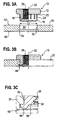
- a fastener 10 which has a flange portion 12 of larger diameter D1 and a shank portion 14 of smaller diameter D2 uf réelle, which extends away from the flange 12 and at its end facing away from the flange 12 end 16 merges into a cylindrical rivet portion 18 whose outer side 20 at least substantially is flush with the outside of the sheep part 14, that has the same diameter D2.
- the side of the flange part facing the shaft part 14 forms a sheet metal contact shoulder 22, and anti-rotation features 24 are provided on the shaft part 14.
- the anti-rotation features could also be provided on the sheet metal abutment shoulder (not shown) or arranged both on the sheet metal abutment shoulder 22 and on the shank part 14, for example with a rectangular shape or with a triangular shape in side view.
- the fastener 10 is designed for use with sheet metal parts with thicknesses in the range of 3 mm and larger.
- the attachment to a relatively thin sheet metal part is now based on the Fig. 2A to 2C described.
- the sheet metal part 25 is at least in the region 26 of the attachment of the fastener before and after attachment of the fastener in a plane.
- fastener shown here is a nut member with internal thread 28.
- the fastener could optionally also be designed as a bolt element.
- shank part 14 would be extended with a threaded portion and the cylindrical rivet would then be formed in a known manner as a skirt, similar to, for example, in the aforementioned US Patent No. 5,251,370 shown in Fig. 8.
- the anti-rotation lugs 24 extend in the axial direction 32 of the shaft part along this. They could instead or additionally extend in radial directions on the sheet metal platen 22 (not shown).
- the sheet metal part in the version according to Fig. 2A to 2C is considered a thinner sheet metal part and has a thickness in the range of 3 to 4.5 mm.
- flange part is circular in radial cross-section or in plan view and that the flange part has a spherical shape in side view.
- the fastener 10 has a hollow shank portion 14 and that the central thread 28 extends through the flange portion 12 and the shank portion 14 and merges into the rivet portion 18 via a tapered thread entry 34 and a radial shoulder 36.
- the assembly part after the Figs. 2B and 2C with a thinner sheet metal part 25 is made by pre-punching it with a punch and die to form a smooth perforated cylindrical opening 40 having a diameter D2 at least substantially equal to the diameter of the shank part 14.
- the sheet metal part 25 is inserted in a press between a die in the lower tool of the press and a punch in the upper tool of the press or in an intermediate plate of the press, wherein the die has an opening with a diameter which is only slightly larger as the diameter of the punch, which corresponds to the diameter D2.
- the press is closed, the punch is pushed through the sheet metal part and a punching slug is produced which is pressed through the opening of the die and disposed of. Characterized in that the opening of the die at least substantially equal to the outer diameter of the punch and only slightly larger than this, creates a cylindrical hole 40 with smooth walls in the sheet metal part.
- the die on the intermediate plate of the press and the punch in the upper die the press or the stamp on the lower tool of the press and the die above the punch on the upper tool of the press or to attach to the intermediate plate of the press.
- the punch could be attached to the intermediate plate of the press and the die on the upper tool of the press.
- mount the die and the stamp in a so-called C-frame and make by appropriate hydraulic load of one or the other part, ie the die or the punch, the perforation of the sheet metal part.
- the shaft part 14 of the fastening element 10 is pressed through the cylindrical perforation 40 until the sheet metal abutment shoulder 22 of the flange part 12 bears against the one side 42 of the sheet metal part and the anti-rotation features or noses 24 have burrowed into the sheet metal part.
- the cylindrical rivet portion 18 is formed by means of a suitable die (not shown) to a Nietbördel 44 which rests on the sheet metal contact shoulder 22 facing away from side 46 of the sheet metal part.
- the attachment of the fastener to the sheet metal part is usually carried out in a press.
- the fastening element 12 is usually taken up in a setting head, and it is positioned below the sheet metal part a rivet with a front end with a shape complementary to the Nietbördel 44 on the underside of the sheet metal part.
- the die may for example have an annular groove in the end face, which resembles a semicircle in radial cross section, as well as the Nietbördel 44. That is, the semicircular annular groove in the end face of the die surrounds a projection which fits radially in the region 46 within the Nietbördels 44 and to the annular shoulder 36 abuts.
- the Fastener moves from a position above the sheet metal part 25 so that the shaft portion 14 of the fastener moves through the perforation 40 until the rivet portion 18 comes into contact with the annular groove of the die, not shown, and the Nietbördel is shaped accordingly.
- the press also provides the necessary force to force the anti-rotation tabs 24 through the side wall of the perforation, thereby forming axially extending furrows in the cylindrical sidewall of the perforation 40 by the anti-rotation tabs 24.
- the rivet can be attached to the lower tool of the press and the setting head on the upper tool of the press or on an intermediate plate of the press or in a reverse arrangement, the setting head can be attached to the lower tool of the press or on the intermediate plate of the press, while the Riveting die is mounted on the intermediate plate or on the upper tool of the press.
- the Nietmatrize or the setting head can be supported by a corresponding actuator of a C-shaped frame.
- the corresponding tools can be designed as progressive dies, wherein in a first station, the perforation is made and in a second station, the fastener is guided into the previously produced perforation.
- the follow-on composite tool can also have other stations, so that further steps in the press are made simultaneously.
- Such an arrangement works by continuously moving the sheet metal part through the press, so that machining operations on the sheet metal strip in each work station of the press are carried out simultaneously with each stroke of the press. After leaving In the press or in the press, the individual sheet metal parts are then separated from each other or from the bleaching strip.
- a stepped hole 50 is made in the sheet metal part with a cylindrical, the sheet metal bearing shoulder facing hole portion 52 of smaller diameter D2, which corresponds to the diameter D2 of the shaft portion 14 at least substantially and with a hole portion 54 of larger diameter.
- the stepped hole 50 can be made, for example, by a boring process or by a two-stage pressing process.
- the sheet metal part 25 is first punched with a punch and a die as described above, wherein the sheet metal part is perforated slightly larger than necessary, ie with a diameter which is slightly larger than D2 or, as below explained in more detail, conically perforated, so that a divergent cone-shaped perforation is formed.
- the sheet metal part is then in a further processing station with a second punch on one side (the bottom 46 in Fig. 3 ) to produce the hole area of larger diameter with the second punch.
- metal flows into the previously created hole so that the hole diameter in the smaller diameter hole part is reduced, preferably to a value corresponding to D2.
- the shaft portion 14 of the fastener 10 is then as in the Fig. 2A to 2C - Embodiment described through the hole 50 pressed until the sheet metal bearing shoulder 22 of the flange 12 abuts on one side 42 of the sheet metal part and the anti-rotation features or -nasen 24 have burrowed into the sheet metal part as indicated at 30.
- the cylindrical rivet portion 18 is formed into a rivet crimp 44, which is received in the hole portion 54 of larger diameter.
- the lower sheet side 46 forms a planar mounting surface for another component, ie the Nietbördel 44 does not protrude beyond the bottom plate 46.
- FIG. 4A to 4D A further variant of the method for producing the assembly component according to the invention is in the Figs. 4A to 4D illustrated by drawings.
- This method can be used with thicker sheet metal parts or with medium thickness sheet metal parts, showing the use of the method with a medium thickness sheet metal part here.
- a die 66 is used here, which has a circular opening 68 with a diameter D2 greater than the diameter D2 of the cylindrical punch 60.
- the middle passage 69 of the die below the opening 68 is also cone-shaped (or stepped) to pass the punched joint.
- the taper of the cone-diverging portion 62 of the hole in the sheet metal part can be selected by choosing the diameter D3 of the opening 68 of the die in comparison to the diameter D1 of the punch within the required limits. Preferably, one aims at an included cone angle of, for example, about 7 °.
- the punch 60 and the die 66 are used in a press as described in connection with the embodiment according to FIGS. 2A to 2C (alternatively, a C-frame can also be used), as also described above.
- dia- meter When using a punch with a larger diameter dia- meter first begins to cut the free end of the punch to a punched slug from the sheet metal part. As soon as the cutting forces reach a certain value, the material breaks, so that a cone-shaped punching slug is pressed out of the sheet metal part. This manner of formation results in the top portion of the perforation, as shown at 64, being in the shape of a circular cylinder corresponding to the shape of the punch 60, while the lower portion 62 in this example receives the desired cone shape.
- the attachment of the fastener to the sheet metal part also takes place in a press, ie in another station of the same press or in a separate press.
- the shaft portion 14 of the fastener 10 is pressed through the perforation 62 until the sheet metal contact shoulder 22 of the flange 12 rests against the one side 42 of the sheet metal part 25 and the anti-rotation features or -nasen 24 have buried in the sheet metal part 25 as indicated at 30.
- the cylindrical rivet section 18 is reshaped by means of a corresponding Nietmatrize to a cone-shaped Nietbördel 44, which wedges in the cone-shaped diverging hole 62.
- the rivet section on the outside 70 acquires a likewise divergent cone shape, which is adapted to the conical shape of the perforation 62. It can be seen that the rivet bead 44 is also completely above the lower side 46 of the sheet metal part 25 here, i. the page 46 also forms a planar Anschraubseite here.
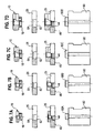
- FIGS. 6A to 6D which basically show the same thing as the one in each case Figures 4B and 4C , but together with the rivet matrix used 80. It can be seen that according to the FIG. 4C the Nietbördel 44 just above the bottom 46 of the sheet metal part 25 comes to an end. One also sees from a comparison of the drawings of the Figs.
- the rivet die has in each case a die projection 80A, 80B, 80C and 80D, which serve for the beading, ie the widening and Deformation of the rivet portion 18 of the element is designed, the die projection 80A to the thread size M8, the die projection 80B to the thread size M 10, the projection 80C to the thread size M 12 and the die projection 80D is adapted to the thread size M 14.
- the invention is by no means limited to these thread sizes, but other thread sizes can be processed in the same way, ie also elements with thread sizes of M20 and more.
- FIG. 7 shows then the same procedure with a thicker sheet metal part where the widened rivet flange 44 now significantly above the bottom plate 46 comes to an end, since just the sheet metal part 25 is here significantly thicker than the sheet metal part 25 of the FIGS. 6A to 6D ,
- the matrices for the thread sizes M8, M 10, M 12 and M 14 are shown. It can be seen that the die protrusion 80A, 80B, 80C and 80D here, although a similar shape as in the embodiment according to FIGS. 6A to 6D has, however, a greater axial height, so that the widening of the rivet portion of the fastener 10 in the desired manner can be made.
- the show Figs. 5A to 5D the dies used for the thread sizes M8, M10, M12 and M14 to form the rivet crimp 44 within the larger diameter hole portion 54 at a stepped hole 50.
- the fasteners are chosen so that the shank portion 14 fails relatively short. If the shaft part is made even shorter, this embodiment can also be used for the thinnest metal sheets, ie, for example, of 3 mm or slightly larger, for example, 4.5 mm thick, so that it is possible to prevent the rivet bead from reaching the lower side 46 of the sheet metal part 25 protrudes.
- the rivet matrices for the thread sizes M8, M 10, M 12 and M 14 are shown.
- thread size cover with one element a wide range of sheet thicknesses, for example from 3 mm to 20 mm or even more. In this way, despite the rather small numbers required for example for trucks, but overall larger numbers of items achieved, so that they can be produced inexpensively. Also, the storage of the elements simplified in this way.
- anti-rotation features described and / or claimed in this application could be performed not only by surveys, but also by depressions on the fastener. In this case, the fastener or the nut member must have a slight excess over the bore. It would also be possible to use a mixture of elevated and past anti-rotation features, for example a sequence of alternating anti-rotation noses and recesses which are located around the circumference of the shaft part and / or on the sheet-metal shoulder and preferably, as well as the antirotation features described so far, at regular intervals are arranged.
- the total number of anti-rotation features is not critical and may be readily provided around the longitudinal axis of the fastener, without limitation, from 2 to 18 and preferably 3 to 12 anti-rotation features.
- the fasteners all materials can be mentioned, which reach the strength values of Class 8 according to ISO standard or higher in the context of cold working, for example a 35B2 alloy according to DIN 1654.
- the fasteners thus formed are suitable i.a.
- steel materials for drawable sheet metal parts as well as for aluminum or its alloys.
- aluminum alloys, especially those with high strength, may be used for the fasteners, e.g. AlMg5.
- fasteners made of higher-strength magnesium alloys such as AM50 come into question.
Abstract
Description
Die vorliegende Erfindung betrifft ein Zusammenbauteil bestehend aus einem Befestigungselement und einem Blechteil sowie ein Verfahren zur Herstellung eines solchen Zusammenbauteils. Bei der Herstellung von PKW-Karosserien und -teilen ist es gang und gäbe mit Befestigungselementen zu arbeiten, die in Form von Nietelementen, Stanz- und Nietelementen oder Einpresselementen vorliegen.The present invention relates to an assembly part consisting of a fastening element and a sheet metal part and a method for producing such a component assembly. In the production of car bodies and parts, it is commonplace to work with fasteners that are in the form of rivet elements, punching and riveting or pressing elements.
Bei einem Nietelement wird das Element in einem vorgelochten Blechteil eingesetzt und durch Umbördeln des Nietabschnitts des Befestigungselements am Blechteil vernietet. Das Befestigungselement selbst hat ein Befestigungsteil, d.h. entweder ein Innengewinde oder einen Bolzenschaft mit Außengewinde, wodurch ein weiteres Bauteil an das Blechteil unter Anwendung einer Schraube bzw. einer Mutter befestigt werden kann. Stanz- und Nietelemente sind selbststanzend ausgebildet, d.h. das Element schneidet selbst das Loch im Blechteil und wird anschließend mit dem Blechteil vernietet. Bei Einpresselementen wird das Blechteil wiederum auch vorgelocht und das Element dann durch das Loch hindurch geführt und mit dem Blechteil verpresst, so dass Blechmaterial in Hinterschneidungen des Einpresselementes hineinfließt und das Einpresselement gegenüber dem Blechteil verriegelt, so dass es fest am Blechteil befestigt ist und nicht ohne weiteres aus dem Blechteil herausgepresst werden kann.In a rivet element, the element is inserted in a pre-punched sheet metal part and riveted by crimping the rivet portion of the fastener on the sheet metal part. The fastener itself has a fastener, ie, either an internal thread or a male threaded stud stem, whereby another component can be secured to the metal sheet member using a nut. Punching and riveting elements are self-piercing, ie the element itself cuts the hole in the sheet metal part and is then riveted to the sheet metal part. In press-in elements, the sheet metal part is in turn also pre-perforated and then passed through the hole and pressed with the sheet metal part, so that sheet material flows into undercuts of the press-in and locks the press-in against the sheet metal part, so that it is firmly attached to the sheet metal part and not without Another can be pressed out of the sheet metal part.
Solche Befestigungselemente haben im PKW-Bau zum Großteil Schweißelemente verdrängt, die bisher an Karosserieblechen und dergleichen angeschweißt wurden. Das Anschweißen von Elementen lässt sich einerseits schlecht in die Herstellung der einzelnen Blechteile durch mechanische Verformung integrieren und führt aber auch zu einer ungewollten Verschmutzung des Blechteils. Ferner können Schweißelemente und kann auch mit verschiedenen Blechteilen nicht verwendet werden, beispielsweise dann, wenn diese vorlackiert sind oder aus zwei Blechteillagen bestehen, gegebenenfalls mit einer dazwischen gelegten Kunststoffmembran. Sie können auch dann nicht verwendet werden, wenn es sich bei dem Blechteil um ein hochfestes Teil handelt, da die mit der Anschweißung einhergehende Wärme zu einer unannehmbaren Herabsetzung der Blecheigenschaften im Bereich der Anschweißstelle führt. Bei der Herstellung von Blechteilen für PKWs werden große Stückzahlen benötigt und die in Frage kommenden Blechteildicken liegen üblicherweise im Bereich von 0,6 mm bis 2,5 mm, gelegentlich darüber hinaus bis 3 mm oder etwas mehr.Such fasteners have largely displaced welding elements in car construction, which were previously welded to body panels and the like. On the one hand, the welding of elements can be poorly integrated into the production of the individual sheet-metal parts by mechanical deformation, but also leads to unwanted contamination of the sheet-metal part. Furthermore, welding elements and can not be used with different sheet metal parts, for example, if they are pre-painted or consist of two sheet metal sections, optionally with an interposed plastic membrane. They can not be used even if the sheet metal part is a high strength part because the heat associated with the weld results in unacceptable degradation of the sheet properties around the weld point. In the production of sheet metal parts for cars, large quantities are required and the sheet metal thicknesses in question are usually in the range of 0.6 mm to 2.5 mm, occasionally beyond to 3 mm or slightly more.
Aus der
Ein Befestigungselement dieser Art wird entsprechend dem genannten US-Patent mittels des so genannten Klemmlochnietverfahrens am Blechteil angebracht. Zu diesem Zweck wird das Blechteil vorgelocht und der Bereich um die Vorlochung zu einer konusförmigen Ausformung bzw. zu einem konusförmigen Bund verformt. Bei der Durchführung des Nietabschnitts des Elements durch das Blechteil, die von der Seite der konusförmigen Ausformung erfolgt, wird der Nietabschnitt umgebördelt und geweitet und es wird gleichzeitig die konusförmige Ausformung zumindest teilweise rückgängig gemacht, wodurch das Loch der konusförmigen Ausformung im Durchmesser verkleinert wird. Es erfolgt eine Art Würgegriff zwischen dem Blechteil und dem Befestigungselement, der für ausgezeichnete, mechanische Eigenschaften der Verbindung zwischen dem Befestigungselement und dem Blechteil sorgt. Die konusförmige Ausformung des Blechteils wird für unterschiedliche Blechdicken unterschiedlich gestaltet, so dass es gelingt, mit einem Element verschiedene Blechdicken abzudecken.A fastener of this type is according to said US Patent by means of the so-called Klemmlochnietverfahrens on sheet metal part appropriate. For this purpose, the sheet metal part is pre-perforated and deformed the area around the pre-perforation to a conical shape or to a cone-shaped collar. When the rivet portion of the member is passed through the sheet member from the side of the cone-shaped formation, the rivet portion is crimped and widened and at the same time the cone-shaped formation is at least partially reversed, thereby reducing the diameter of the hole of the cone-shaped formation. There is a kind of choke grip between the sheet metal part and the fastener, which provides excellent, mechanical properties of the connection between the fastener and the sheet metal part. The conical shape of the sheet metal part is designed differently for different sheet thicknesses, so that it is possible to cover different sheet thicknesses with one element.
In der Patentschrift wird zum Ausdruck gebracht, dass das Element mit Blechteildicken bis zum 4 mm verwendet werden kann, wobei, wie oben gesagt, Blechteildicken oberhalb von 3 mm im PKW-Bau relativ selten sind.In the patent it is stated that the element can be used with sheet metal thicknesses up to 4 mm, which, as stated above, sheet metal thicknesses above 3 mm in the car construction are relatively rare.
Nietelemente finden auch bei der Herstellung von LKWs Anwendung, jedoch in einem weitaus geringeren Ausmaß. Im Wesentlichen ist nur die Anwendung von Nietelementen aus der PKW-Herstellung bekannt, die auch in dünnen Blechteilen von LKWs, beispielsweise im Bereich der Fahrerkabine, zur Anwendung gelangen. Stabilere Blechteile der LKWs, d.h. mit Blechdicken größer als 3 mm und üblicherweise von 4 mm und noch größer, sind - wenn überhaupt - nur in den seltensten Fällen mit Nietelementen versehen, da die verfügbaren Nietelemente eben nicht für solche dicken Blechteile ausgelegt sind. Ferner werden weitaus weniger LKWs im Vergleich zu PKWs hergestellt. Die bei der LKW-Herstellung verwendeten Verfahren führen dazu, dass Schweißelemente dort dominieren.Rivet elements are also used in the manufacture of trucks, but to a much lesser extent. Essentially, only the application of rivet elements from the manufacture of cars is known, which are also used in thin sheet metal parts of trucks, for example in the area of the driver's cab. Stable sheet metal parts of trucks, ie with sheet thicknesses greater than 3 mm and usually 4 mm and even larger, are - if at all - only in the rarest cases provided with rivet elements, since the available rivet elements are just not designed for such thick sheet metal parts. Furthermore, far fewer trucks are being used Made compared to cars. The processes used in truck production mean that welding elements dominate there.
Die Aufgabe der vorliegenden Erfindung ist es, ein Zusammenbauteil bestehend aus einem Nietelement und einem Blechteil sowie ein Verfahren zur Herstellung eines solchen Zusammenbauteils vorzuschlagen, das selbst bei geringeren Stückzahlen eine kostengünstige Lösung darstellt und rationell verwendet werden kann.The object of the present invention is to propose an assembly component consisting of a rivet element and a sheet metal part as well as a method for producing such an assembly component, which represents a cost-effective solution even with smaller quantities and can be used efficiently.
Zur Lösung dieser Aufgabe wird erfindungsgemäß ein Zusammenbauteil der oben genannten Art vorgeschlagen, dass sich dadurch auszeichnet, dass das Befestigungselement zur Anwendung mit Blechteilen mit Dicken im Bereich von 3 mm und größer ausgelegt ist, und dass das Blechteil zumindest im Bereich der Anbringung des Befestigungselements vor und nach Anbringung des Befestigungselements in einer Ebene liegt und
- a) bei relativ dünnen Blechteilen das Blechteil eine glatt gelochte zylindrische Öffnung aufweist, die einen Durchmesser hat, der zumindest im Wesentlichen dem Durchmesser des Schaftteils entspricht, wobei der zylindrische Nietabschnitt zu einem Nietbördel umgeformt ist, das auf der der Blechanlageschulter abgewandten Seite des Blechteils anliegt, oder
- b) bei Blechteilen mittlerer Dicke das Blechteil ein gestuftes Loch aufweist mit einem zylindrischen, der Blechanlageschulter zugewandten Lochteil kleineren Durchmessers, der dem Durchmesser des Schaftteils zumindest im Wesentlichen entspricht und mit einem Lochbereich größeren Durchmessers, der den zu einem Nietbördel umgebördelten Nietabschnitt aufnimmt, oder
- c) bei relativ dicken Blechteilen, bei denen das Blechteil eine Dicke aufweist, die zumindest im Wesentlichen der Gesamtlänge des Schaftteils und des Nietabschnitts entspricht oder dicker ist, das Blechteil mit einer konusförmigen Lochung vorgesehen ist, die in Richtung von der die Blechanlageschulter zugewanden Seite des Blechteils zu der dieser abgewandten Seite hin divergiert, wobei der zylindrische Nietabschnitt zu einem konusförmigen Nietbördel umgeformt ist, das in der konusförmig divergierenden Lochung verkeilt ist.
- a) at relatively thin sheet metal parts, the sheet metal part has a smooth perforated cylindrical opening which has a diameter which corresponds at least substantially to the diameter of the shaft portion, wherein the cylindrical rivet portion is formed into a Nietbördel which rests on the sheet metal bearing shoulder facing away from the sheet metal part , or
- b) in sheet metal parts of medium thickness, the sheet metal part has a stepped hole with a cylindrical, the sheet metal bearing shoulder facing hole portion of smaller diameter, which corresponds to the diameter of the shaft portion at least substantially and with a hole area of larger diameter, which accommodates the riveted to a Nietbördel rivet, or
- c) in relatively thick sheet metal parts, wherein the sheet metal part has a thickness which is at least substantially the total length of the shank portion and the rivet portion or thicker, the sheet metal part is provided with a cone-shaped perforation, in the direction of the Blechchanlageschulter zugewanden side of the sheet metal part to the opposite side diverges, wherein the cylindrical rivet portion is formed into a cone-shaped Nietbördel which is keyed in the cone-shaped diverging hole.
Es wird somit ein Befestigungselement vorgeschlagen, das zwar eine Grundform hat, die an sich bekannt ist, dass aber durchaus auch zur Anwendung mit Blechteilen dicker als 3 mm verwendet werden kann, wenn das Blechteil entsprechend vorbearbeitet wird.It is thus proposed a fastener, which indeed has a basic shape, which is known per se, but that can also be used for use with sheet metal parts thicker than 3 mm, when the sheet metal part is prepared accordingly.
Es ist zunächst wesentlich, dass das Blechteil zumindest im Bereich der Anbringung des Befestigungselements sowohl vor als auch nach der Anbringung des Befestigungselements in einer Ebene liegt. D.h., das Blechteil wird nicht konusförmig angestellt wie beim Klemmlochnieten, sondern das Blech bleibt in einer Ebene, sowohl bei der Vorlochung als auch bei der Anbringung des Elements.It is first of all essential that the sheet metal part lies in a plane at least in the region of the attachment of the fastening element both before and after the attachment of the fastening element. That is, the sheet metal part is not employed in a cone shape as in the Klemmlochnieten, but the sheet remains in a plane, both in the pre-punching as well as in the attachment of the element.
Dies schließt zwar nicht aus, dass das Blech vor oder nach dem Lochvorgang zu einer Sicke umgeformt wird, wobei das Befestigungselement im planaren Bodenbereich der Sicke angebracht wird, sondern das bedeutet, dass das Blechteil sowohl im unmittelbaren Bereich der Anbringung des Befestigungselements als auch in radialen Richtungen benachbart zur Anbringungsstelle in einer Ebene liegt.Although this does not exclude that the sheet is formed into a bead before or after the hole process, wherein the fastener is mounted in the planar bottom portion of the bead, but that means that the sheet metal part both in the immediate area of attachment of the fastener as well as in radial Directions adjacent to the attachment point in a plane.
Bei relativ dünnen Blechteilen, die beispielsweise eine Dicke zwischen 3 mm und 4,5 mm aufweisen können, kann der Nietabschnitt der aus der Seite des Blechteils herausragt, die der Blechanlageschulter abgewandt ist, zu einem Nietbördel umgebördelt werden, wobei das Nietbördel dann sozusagen auf der Unterseite des Blechs anliegt, wenn die Blechanlageschulter des Flanschteils auf der Blechoberseite anliegt. Um eine planare Anschraubsituation zu erreichen, muss dann entweder mit einer Scheibe mit einem Loch, dass das Nietbördel aufnimmt, oder mit einer aufgeweiteten Bohrung im anzuschraubenden Bauteil gearbeitet werden.For relatively thin sheet metal parts, which may for example have a thickness between 3 mm and 4.5 mm, the rivet portion protruding from the side of the sheet metal part, which faces away from the sheet metal shoulder, are crimped to a Nietbördel, the Nietbördel then so to speak on the Bottom of the sheet rests when the sheet metal shoulder of the flange abuts the top of the sheet metal. To achieve a planar bolting situation, then either with a disc with a hole that receives the Nietbördel, or worked with a widened hole in the component to be screwed.
An sich ist der Gewindedurchmesser des Befestigungselements nicht auf irgendwelche bestimmten Größen beschränkt, nur werden beim LKW-Bau und gerade bei dickeren Blechen nur selten Schrauben verwendet, die Gewinde kleiner als M8 aufweisen, wobei Gewindegrößen von M20 und größer keine Seltenheit sind.In itself, the thread diameter of the fastener is not limited to any particular sizes, only in the truck construction and just in thicker sheets are rarely used screws that have threads smaller than M8, with thread sizes of M20 and larger are not uncommon.
Bei etwas dickeren Blechen, beispielsweise im Bereich zwischen 4,5 mm und 6,5 mm wird erfindungsgemäß vorzugsweise mit einem gestuften Loch im Blechteil gearbeitet, wobei das Nietbördel in den Lochbereich größeren Durchmessers aufgenommen wird, d.h. nicht aus der Unterseite des Blechteils hinausragt. Dies macht die Verwendung einer gesonderten Scheibe oder das Vorsehen einer gesonderten Ausnehmung im anzuschraubenden Bauteil überflüssig.In the case of somewhat thicker sheets, for example in the range between 4.5 mm and 6.5 mm, it is preferable according to the invention to work with a stepped hole in the sheet metal part, with the rivet bead being received in the hole area of larger diameter, i. does not protrude from the bottom of the sheet metal part. This makes the use of a separate disc or the provision of a separate recess in the component to be screwed superfluous.
Für dicke Blechteile, beispielsweise mit einer Dicke größer als 6,5 mm wird vorzugsweise durch einen Lochvorgang ein Loch im Blechteil erzeugt, das in Richtung von der Seite des Blechteils, die der Blechanlageschulter zugewandt ist zu der abgewandten Seite des Blechteils gehend konusförmig divergierend ausgebildet ist, und es wird der Nietabschnitt dann nicht zu einem umgelegten Nietbördel, sondern zu einer Konusform verformt, so dass der Nietabschnitt sich in der konusförmig divergierenden Lochung verkeilt und auf diese Weise verhindert, dass das Befestigungselement aus dem Blechteil herausgepresst wird.For thick sheet metal parts, for example, with a thickness greater than 6.5 mm, a hole in the sheet metal part is preferably produced by a punching process, which is in the direction of the side of the sheet metal part, which faces the sheet metal contact shoulder to the opposite side of the sheet metal part is divorced cone-shaped , And then the rivet portion is not deformed into a folded rivet, but to a cone shape, so that the rivet portion wedged in the cone-shaped diverging perforation and thus prevents the fastener is pressed out of the sheet metal part.
Das Befestigungselement ist normalerweise als Mutterelement ausgebildet, d.h. sowohl der Flanschteil als auch der Schaftteil sind hohl ausgebildet mit einem ein Innengewinde aufweisenden Hohlraum. Das Gewinde erstreckt sich jedoch nicht in den Nietabschnitt hinein, da es sonst durch die Umbördelung des Nietabschnitts verformt wird. Stattdessen geht der Nietabschnitt üblicherweise über eine Ringschulter und einen Einlaufkonus in der hohle Schaftteil, d.h. in das Gewinde hinein. Das Vorsehen einer solchen Ringschulter ermöglicht es einerseits, den Nietabschnitt in der radialen Dicke auf ein geeignetes Maß klein und gut verformbar zu halten, den Schaftteil aber dennoch ausreichend dick auszubilden, dass das Befestigungselement eine erhebliche Stabilität hat und damit der Verwendung in einem LKW gerecht wird.The fastening element is normally designed as a nut element, ie both the flange part and the shaft part are hollow with a cavity having an internal thread. However, the thread does not extend into the rivet section, otherwise it will pass through the flanging of the rivet section is deformed. Instead, the rivet section usually passes over an annular shoulder and an inlet cone in the hollow shaft part, ie in the thread. The provision of such an annular shoulder makes it possible, on the one hand, to keep the rivet section small and well deformable in the radial thickness to a suitable level, but nevertheless to make the shaft part sufficiently thick that the fastening element has a considerable stability and thus is suitable for use in a truck ,
Diese Ausführungsform ist besonders günstig, weil eine konusförmig divergierende Lochung dieser Art presstechnisch erfindungsgemäß relativ leicht erzeugt werden kann, und zwar auch über erhebliche Blechdicken, wobei das konusförmige Nietbördel an einer der Gesamtlänge des Schaftteils mit Nietabschnitt entsprechenden Stelle der Lochung erfolgt. Es ist lediglich erforderlich, eine für die jeweilige Blechdicke passende Matrize auszuwählen, um die Aufweitung des Nietabschnitts zu der Konusform zu erreichen.This embodiment is particularly advantageous because a conically diverging perforation of this type can be produced relatively easily according to the invention, and indeed over considerable plate thicknesses, wherein the conical Nietbördel takes place at one of the total length of the shaft portion with rivet portion corresponding point of the perforation. It is only necessary to select a suitable for the respective sheet thickness die to achieve the expansion of the rivet portion to the cone shape.
Bei der Anbringung des Befestigungselements an das jeweilige Blechteil werden etwaige Verdrehsicherungsnasen, die am Befestigungselement vorgesehen sind, in das Blechteil hineingepresst und bilden dort entsprechende Vertiefungen, die im Zusammenhang mit den Verdrehsicherungsnasen die erforderlich Verdrehsicherung erzeugen.When attaching the fastener to the respective sheet metal part any anti-rotation lugs, which are provided on the fastener, pressed into the sheet metal part and form there corresponding recesses, which generate the necessary rotation in conjunction with the anti-rotation lugs.
Die Verdrehsicherungsnasen erstrecken sich vorzugsweise in axialer Richtung des Schaftteils an diesem entlang und/oder sie erstrecken sich in radialen Richtungen an der Blechanlageschulter.The anti-rotation lugs preferably extend in the axial direction of the shaft part along this and / or they extend in radial directions on the sheet metal contact shoulder.
An dieser Stelle soll zum Ausdruck gebracht werden, dass es nicht zwingend erforderlich ist, das Element so auszulegen, dass dünnere Bleche im Bereich zwischen 3 bis 4,5 mm, Blechteile mittlerer Dicke eine Dicke im Bereich von 4,5 bis 6,5 mm und dickere Blechteile eine Dicke größer als 6,5 mm aufweisen.At this point, it should be emphasized that it is not absolutely necessary to design the element so that thinner sheets in the Range between 3 to 4.5 mm, medium thickness sheet metal parts have a thickness in the range of 4.5 to 6.5 mm and thicker sheet metal parts have a thickness greater than 6.5 mm.
Die Aussage, dass bei dünneren Blechteilen mit einer Dicke im Bereich von 3 bis 4,5 mm sich das Nietbördel sich auf der Unterseite des Blechteils befindet, bedeutet, dass der Schaftteil des Element so ausgelegt ist, dass er eine Länge von etwa 3 mm aufweist, während der Nietabschnitt ebenfalls eine axiale Lage von etwa 2,5 mm hat. Da die Gesamtlänge des Gewindes durch die axiale Höhe des Flanschteils und die axiale Länge des Schaftteils bestimmt ist, könnte die Flanschteilhöhe erhöht und Flanschteillänge verringert werden, wodurch das Nietbördel auf der Unterseite des Blechteils dann bei noch dünneren Blechen möglich wäre mit dem Ergebnis, dass Blechteile mittlerer Dicke dann bei niedrigen Stärken anfangen, beispielsweise jetzt bei 4 mm, da auch bei dieser Blechstärke ein gestuftes Loch hergestellt werden kann, bei dem der Lochbereich größeren Durchmessers auch geeignet ist, den umgebördelten Nietabschnitt aufzunehmen, so dass, wie oben erläutert, sich eine planare Anschraubfläche ergibt mit den daraus resultierenden Vorteilen. Es würde aber auch bedeuten, dass man für Blechteile mit einer Dicke von beispielsweise 5,5 mm dann eine Lochung vorbereiten könnte, die konusförmig divergiert, so dass das gestufte Loch, was in der Herstellung etwas komplizierter ist, gar nicht mehr erforderlich wäre.The statement that with thinner sheet metal parts having a thickness in the range of 3 to 4.5 mm, the Nietbördel is located on the underside of the sheet metal part, means that the shaft portion of the element is designed so that it has a length of about 3 mm while the rivet portion also has an axial position of about 2.5 mm. Since the total length of the thread is determined by the axial height of the flange portion and the axial length of the shank portion, the Flanschteilhöhe increased and flange pitch could be reduced, whereby the Nietbördel on the underside of the sheet metal part would then be possible with even thinner sheets with the result that sheet metal parts medium thickness then start at low strengths, for example, now at 4 mm, since even with this plate thickness a stepped hole can be produced in which the hole portion of larger diameter is also suitable to receive the flanged rivet section, so that, as explained above, a planar mounting surface yields with the resulting advantages. But it would also mean that for sheet metal parts with a thickness of, for example, 5.5 mm could then prepare a hole that diverges conically, so that the stepped hole, which is slightly more complicated in the production, would no longer be required.
Aus den obigen Erläuterungen geht hervor, dass man nicht alle drei erfindungsgemäßen Möglichkeiten haben muss, und dass besonders bei einer Lochung mit konusförmig divergierender Lochung sich besondere Vorteile ergeben, zumal eine solche Konusform relativ leicht herzustellen ist.From the above explanations, it is clear that not all three possibilities according to the invention must be available, and that special advantages arise in particular in the case of perforations with a conically diverging perforation, especially since such a cone shape is relatively easy to produce.
Der Flanschteil des Befestigungselements ist im radialen Querschnitt kreisrund. Das Element kann somit durch Kaltverformung vorteilhaft aus Rundstabmaterial hergestellt werden. Durch die Herstellung aus Rundstabmaterial kann der Flanschteil in Seitenansicht eine ballige Form aufweisen, die einerseits eine ausreichende Festigkeit des Flanschteils durch Kaltverformung und andererseits eine ausreichende radiale Erstreckung der Blechanlageschulter sicherstellt, so dass die Flächenpressung klein gehalten werden kann. Auch die Vermeidung von scharfen Kanten, die durch die ballige Form nicht vorkommen, ist von Vorteil.The flange of the fastener is circular in radial cross-section. The element can thus be advantageously made by cold deformation of round rod material. Due to the production of round rod material, the flange part in side view may have a crowned shape, which on the one hand ensures sufficient strength of the flange part by cold deformation and on the other hand sufficient radial extent of the sheet metal contact shoulder, so that the surface pressure can be kept small. The avoidance of sharp edges, which do not occur due to the spherical shape, is an advantage.
Man kann somit drei unterschiedliche Arten der Anbringung des Befestigungselements zur Herstellung des Zusammenbauteils ins Auge fassen. Mit einem dünneren Blechteil wird dieses mit einem Lochstempel vorgelocht, um eine glatt gelochte zylindrische Öffnung auszubilden, die einen Durchmesser hat, der zumindest im Wesentlichen dem Durchmesser des Schaftteils entspricht, wobei der Schafteil des Befestigungselements dann durch die zylindrische Lochung hindurchgepresst wird bis die Blechanlageschulter des Flanschteils an der einen Seite des Blechteils anliegt und die Verdrehsicherungsmerkmale bzw. -nasen sich in das Blechteil eingegraben haben und der zylindrische Nietabschnitt mittels einer geeigneten Matrize zu einem Nietbördel umgeformt ist, das auf der der Blechanlageschulter abgewandten Seite des Blechteils anliegt.It is thus possible to envisage three different ways of attaching the fastening element for producing the assembly part. With a thinner sheet metal part this is pre-perforated with a punch to form a smooth perforated cylindrical opening having a diameter which corresponds at least substantially to the diameter of the shaft portion, wherein the shaft portion of the fastener is then pressed through the cylindrical perforation until the sheet metal bearing shoulder of the Flange member abuts on one side of the sheet metal part and the anti-rotation features or -nasen have burrowed into the sheet metal part and the cylindrical rivet is formed by means of a suitable die to a Nietbördel which rests on the sheet metal bearing shoulder facing away from the sheet metal part.
Mit einem Blechteil mittlerer Dicke wird das Verfahren derart durchgeführt, dass ein gestuftes Loch im Blechteil angefertigt wird mit einem zylindrischen, der Blechanlageschulter zugewandten Lochteil kleineren Durchmessers, der dem Durchmesser des Schaftteils zumindest im Wesentlichen entspricht und mit einem Lochbereich größeren Durchmessers, wobei der Schafteil des Befestigungselements durch das Loch hindurchgepresst wird bis die Blechanlageschulter des Flanschteils an der einen Seite des Blechteils anliegt und die Verdrehsicherungsmerkmale bzw. - nasen sich in das Blechteil eingegraben haben, und der zylindrische Nietabschnitt mittels einer geeigneten Matrize zu einem Nietbördel umgeformt wird, das in den Lochbereich größeren Durchmessers aufgenommen wird.With a sheet metal part of medium thickness, the method is carried out such that a stepped hole in the sheet metal part is made with a cylindrical, the sheet metal bearing shoulder facing hole portion of smaller diameter, which corresponds to the diameter of the shaft portion at least substantially and with a hole area of larger diameter, wherein the sheep part of Fastener is pressed through the hole until the sheet metal bearing shoulder of the flange on the one Side of the sheet metal part rests and the anti-rotation features or - noses have buried in the sheet metal part, and the cylindrical rivet is formed by means of a suitable die to a Nietbördel which is received in the hole area of larger diameter.
Das gestufte Loch wird beispielsweise durch einen Bohrvorgang oder durch einen zweistufigen Pressvorgang hergestellt.The stepped hole is made, for example, by a boring process or by a two-stage pressing process.
Mit einem relativ dicken Blechteil wird so vorgegangen, dass dieses mit einem Lochstempel oder anderweitig vorgelocht wird, um eine konusförmigen Lochung auszubilden, die in Richtung von der der Blechanlageschulter zugewandten Seite des Blechteils zu der dieser abgewandten Seite hin divergiert, wobei die Lochung auf der der Blechanlageschulter zugewandten Seite einen Durchmesser hat, der zumindest im Wesentlichen dem Durchmesser des Schaftteils entspricht, wobei der Schafteil des Befestigungselements durch die Lochung hindurchgepresst wird bis die Blechanlageschulter des Flanschteils an der einen Seite des Blechteils anliegt und die Verdrehsicherungsmerkmale bzw. -nasen sich in das Blechteil eingegraben haben, und der zylindrische Nietabschnitt mittels einer geeigneten Matrize zu einem konusförmigen Nietbördel umgeformt wird, das sich in der konusförmig divergierenden Lochung verkeilt.With a relatively thick sheet metal part is such that this is pre-punched with a punch or otherwise to form a cone-shaped perforation, which diverges in the direction of the sheet metal bearing shoulder facing side of the sheet metal part to the side facing away from this, the perforation on the Blechanlageschulter facing side has a diameter which corresponds at least substantially to the diameter of the shaft portion, wherein the shaft portion of the fastener is pressed through the perforation until the sheet metal bearing shoulder of the flange abuts the one side of the sheet metal part and the anti-rotation features or -nasen itself in the sheet metal part and the cylindrical rivet section is reshaped by means of a suitable die to a cone-shaped rivet bead which wedges in the cone-shaped diverging perforation.
Besonders günstig ist es, wenn sich die konusförmig erstreckende Lochung an einen zylindrischen Bereich der Lochung anschließt, der benachbart zur Blechanlageschulter ausgebildet wird. Der zylindrische Bereich der zumindest im Wesentlichen den gleichen Durchmesser wie der Schaftteil aufweist, sorgt einerseits für eine saubere Führung des Schaftteils des Befestigungselements und andererseits dafür, dass eine möglichst große Verdrehsicherheit in diesem Bereich erzeugt wird, da die Verdrehsicherungsnasen dann über ihre gesamte radiale Tiefe entsprechende Furchen im Lochrand erzeugen.It is particularly favorable when the conically extending perforation adjoins a cylindrical region of the perforation, which is formed adjacent to the sheet-metal contact shoulder. The cylindrical region which has at least substantially the same diameter as the shaft part, on the one hand ensures a clean guidance of the shaft part of the fastening element and on the other hand ensures that the greatest possible security against rotation is generated in this region, since the anti-rotation lugs then create corresponding grooves in the hole edge over their entire radial depth.
Die konusförmige Lochung erfolgt vorzugsweise unter Anwendung einesThe cone-shaped perforation is preferably carried out using a
Lochstempels mit einem Durchmesser entsprechend dem Durchmesser des Schaftteils in Kombination mit einer Lochmatrize größeren Durchmessers. Eine solche Auslegung führt dazu, dass der Lochstempel im Anfangsbereich der Lochung ein glattwandiges Loch schneidet und anschließend einen konusförmigen Stanzbutzen aus der restlichen Dicke des Blechteils heraus bricht, wobei der maximale Durchmesser des Stanzbutzens durch den Durchmesser des Loches der Matrize bestimmt wird. Die Konizität des Stanzbutzens wird durch die Blechdicke, den Durchmesser des Lochstempels und dem Durchmesser des Loches der Matrize bestimmt.Punch with a diameter corresponding to the diameter of the shaft part in combination with a larger diameter perforated die. Such a design results in the punch puncturing a smooth-walled hole in the initial region of the perforation and subsequently breaking a cone-shaped punched billet out of the remaining thickness of the sheet-metal part, the maximum diameter of the punching orifice being determined by the diameter of the hole of the die. The conicity of the stamping is determined by the sheet thickness, the diameter of the punch and the diameter of the hole of the die.
Die Erfindung wird nachfolgend anhand von Ausführungsbeispielen und unter Bezugnahme auf die Zeichnungen näher erläutert, in welcher zeigen:
- Fig. 1A bis 1C
- ein Befestigungselement, das entsprechend der Erfindung mit einem Blechteil zu einem Zusammenbauteil kombiniert werden kann, und zwar in einer Stirnansicht auf den Nietabschnitt in
Fig. 1A in einer teilweise axial geschnittenen seitlichen Darstellung gemäßFig. 1B und in einer perspektivischen Darstellung gemäßFig. 1C , - Fig. 2A bis 2C
- eine Zeichnungsreihe zur Darstellung der Anbringung des Befestigungselements in einem dünneren Blechteil,
- Fig. 3A bis 3C
- eine Skizzenreihe zur Darstellung der Anbringung des Befestigungselements gemäß
Fig. 1A bis 1C an einem Blechteil mittlerer Dicke, - Fig. 4A bis 4D
- eine Zeichnungsreihe zur Darstellung der Anbringung des Befestigungselements gemäß
Fig. 1A bis 1C an einem Blechteil mittlerer Dicke bzw. größerer Dicke, - Fig. 5A bis 5D
- prinzipiell die gleiche Situation wie in
Fig. 3 , jedoch einschließlich der dafür verwendeten Matrize und für die Gewindegrößen M8 (Fig. 5A ), M10 (Fig. 5B ), M12 (Fig. 5C ), M 14 (Fig. 5D ), - Fig. 6A bis 6D
- prinzipiell die gleiche Situation wie in
Fig. 4 , jedoch einschließlich der dafür verwendeten Matrize und für die Gewindegrößen M8 (Fig. 6A ), M10 (Fig. 6B ), M12 (Fig. 6C ), M 14 (Fig. 6D ), - Fig. 7A bis 7D
- eine Zeichnungsreihe entsprechend den
Fig. 6A bis 6D , jedoch für die Anbringung des Befestigungselements gemäßFig. 1A bis 1C an ein einem dickeren Blechteil zusammen mit den dafür verwendeten Matrizen und für die Gewindegrößen M8 (Fig. 7A ), M10 (Fig. 7B ), M12 (Fig. 7C ), M14 (Fig. 7D ),
- Fig. 1A to 1C
- a fastener that can be combined according to the invention with a sheet metal part to an assembly component, in a front view of the rivet in
Fig. 1A in a partially axially sectioned lateral view according toFig. 1B and in a perspective view according toFig. 1C . - Fig. 2A to 2C
- a drawing series to illustrate the attachment of the fastener in a thinner sheet metal part,
- Figs. 3A to 3C
- a series of sketches to illustrate the attachment of the fastener according to
Fig. 1A to 1C on a sheet metal part of medium thickness, - Figs. 4A to 4D
- a series of drawings to illustrate the attachment of the fastener according to
Fig. 1A to 1C on a sheet metal part of medium thickness or greater thickness, - Figs. 5A to 5D
- in principle the same situation as in
Fig. 3 , but including the die used for it and for the thread sizes M8 (Fig. 5A ), M10 (Fig. 5B ), M12 (Fig. 5C ), M 14 (Fig. 5D ) - FIGS. 6A to 6D
- in principle the same situation as in
Fig. 4 , but including the die used for it and for the thread sizes M8 (Fig. 6A ), M10 (Fig. 6B ), M12 (Fig. 6C ), M 14 (Fig. 6D ) - Figs. 7A to 7D
- a series of drawings according to the
FIGS. 6A to 6D , but for the attachment of the fastener according toFig. 1A to 1C to a thicker sheet metal part together with the matrices used for it and for the thread sizes M8 (Fig. 7A ), M10 (Fig. 7B ), M12 (Fig. 7C ), M14 (Fig. 7D )
Das Befestigungselement 10 ist zur Anwendung mit Blechteilen mit Dicken im Bereich von 3 mm und größer ausgelegt.The
Die Anbringung an einem relativ dünnen Blechteil wird nunmehr anhand der
Es handelt sich bei dem hier gezeigten Befestigungselement um ein Mutterelement mit Innengewinde 28. Das Befestigungselement könnte gegebenenfalls auch als Bolzenelement ausgelegt werden. In diesem Falle wäre der Schaftteil 14 mit einem Gewindeteil verlängert und der zylindrische Nietabschnitt wäre dann in an sich bekannter weise als Rock ausgebildet, ähnlich wie beispielsweise in der eingangs genannten
Die Verdrehsicherungsmerkmale 24, die durch Verdrehsicherungsnasen gebildet sind, bilden bei Anbringung des Befestigungselements (wie in
Das Blechteil in der Ausführung gemäß
Es ist ferner aus
Ferner ist ersichlicht, dass das Befestigungselement 10 einen hohlen Schaftteil 14 aufweist und dass das mittlere Gewinde 28 sich durch den Flanschteil 12 und den Schaftteil 14 hindurch erstreckt und über einen konischen Gewindeeinlauf 34 und eine radiale Schulter 36 in den Nietabschnitt 18 übergeht.It is further understood that the
Das Zusammenbauteil nach den
Es soll darauf hingewiesen werden, dass es auch möglich wäre, die Matrize an der Zwischenplatte der Presse und den Stempel im oberen Werkzeug der Presse oder den Stempel am unteren Werkzeug der Presse und die Matrize oberhalb des Stempels am oberen Werkzeug der Presse oder an der Zwischenplatte der Presse anzubringen. Auch könnte der Stempel an der Zwischenplatte der Presse angebracht werden und die Matrize am oberen Werkzeug der Presse. Ferner bestünde die Möglichkeit, die Matrize und den Stempel in einem so genannten C-Gestell zu montieren und durch entsprechende hydraulische Belastung des einen oder anderen Teils, d.h. die Matrize oder den Stempel, die Lochung des Blechteils vorzunehmen.It should be noted that it would also be possible to use the die on the intermediate plate of the press and the punch in the upper die the press or the stamp on the lower tool of the press and the die above the punch on the upper tool of the press or to attach to the intermediate plate of the press. Also, the punch could be attached to the intermediate plate of the press and the die on the upper tool of the press. Furthermore, it would be possible to mount the die and the stamp in a so-called C-frame and make by appropriate hydraulic load of one or the other part, ie the die or the punch, the perforation of the sheet metal part.
Der Schafteil 14 des Befestigungselements 10 wird durch die zylindrische Lochung 40 hindurchgepresst bis die Blechanlageschulter 22 des Flanschteils 12 an der einen Seite 42 des Blechteils anliegt und die Verdrehsicherungsmerkmale bzw. -nasen 24 sich in das Blechteil eingegraben haben. Der zylindrische Nietabschnitt 18 wird mittels einer geeigneten Matrize (nicht gezeigt) zu einem Nietbördel 44 umgeformt, das auf der der Blechanlageschulter 22 abgewandten Seite 46 des Blechteils anliegt.The
Die Anbringung des Befestigungselements an das Blechteil erfolgt üblicherweise auch in einer Presse. Dafür wird das Befestigungselement 12 üblicherweise in einen Setzkopf aufgenommen, und es wird unterhalb des Blechteils eine Nietmatrize positioniert mit einem Stirnende mit einer Form komplementär zum Nietbördel 44 auf der Unterseite des Blechteils. Die Matrize kann beispielsweise eine Ringnut in der Stirnseite aufweisen, die im radialen Querschnitt einem Halbkreis ähnelt, wie auch das Nietbördel 44. D.h., die halbkreisförmige Ringnut in der Stirnseite der Matrize umringt einen Vorsprung, der im Bereich 46 radial innerhalb des Nietbördels 44 hineinpasst und an die Ringschulter 36 anstößt. Außerhalb der Ringnut liegt ebenfalls eine planare Fläche, die in Berührung mit der Unterseite 46 des Blechteils 25 gelangt. Durch Schließen der Presse wird das Befestigungselement von einer Stelle oberhalb des Blechteils 25 so bewegt, dass der Schaftteil 14 des Befestigungselements sich durch die Lochung 40 hindurchbewegt, bis der Nietabschnitt 18 mit der Ringnut der nicht gezeigten Matrize in Berührung gelangt und das Nietbördel entsprechend geformt wird. Die Presse liefert auch die erforderliche Kraft, um die Verdrehsicherungsnasen 24 durch die Seitenwand der Lochung hindurchzupressen, wodurch sich in axialer Richtung erstreckende Furchen in der zylindrischen Seitenwand der Lochung 40 durch die Verdrehsicherungsnasen 24 geformt werden.The attachment of the fastener to the sheet metal part is usually carried out in a press. For this, the
Auch hier kann die Nietmatrize am unteren Werkzeug der Presse und der Setzkopf am oberen Werkzeug der Presse oder an einer Zwischenplatte der Presse angebracht werden oder in einer umgekehrten Anordnung kann der Setzkopf am unteren Werkzeug der Presse oder an der Zwischenplatte der Presse angebracht werden, während die Nietmatrize an der Zwischenplatte bzw. am oberen Werkzeug der Presse montiert ist. Auch hier kann die Nietmatrize oder der Setzkopf von einer entsprechend Betätigungseinrichtung eines C-förmigen Gestells getragen werden.Again, the rivet can be attached to the lower tool of the press and the setting head on the upper tool of the press or on an intermediate plate of the press or in a reverse arrangement, the setting head can be attached to the lower tool of the press or on the intermediate plate of the press, while the Riveting die is mounted on the intermediate plate or on the upper tool of the press. Again, the Nietmatrize or the setting head can be supported by a corresponding actuator of a C-shaped frame.
Wenn eine Presse zur Anwendung gelangt, so können die entsprechenden Werkzeuge als Folgeverbundwerkzeuge ausgelegt werden, wobei in einer ersten Station die Lochung vorgenommen wird und in einer zweiten Station das Befestigungselement in die vorher erzeugte Lochung hineingeführt wird. Das Folgeverbundwerkzeug kann aber auch weitere Stationen haben, so dass auch weitere Arbeitsschritte in der Presse gleichzeitig vorgenommen werden. Eine solche Anordnung funktioniert so, dass das Blechteil kontinuierlich durch die Presse hindurch bewegt wird, so dass bei jedem Hub der Presse Bearbeitungsvorgänge am Blechstreifen in jeder Arbeitsstation der Presse gleichzeitig durchgeführt werden. Nach dem Verlassen der Presse oder in der Presse werden dann die einzelnen Blechteile voneinander bzw. vom Bleichstreifen getrennt.If a press is used, then the corresponding tools can be designed as progressive dies, wherein in a first station, the perforation is made and in a second station, the fastener is guided into the previously produced perforation. The follow-on composite tool can also have other stations, so that further steps in the press are made simultaneously. Such an arrangement works by continuously moving the sheet metal part through the press, so that machining operations on the sheet metal strip in each work station of the press are carried out simultaneously with each stroke of the press. After leaving In the press or in the press, the individual sheet metal parts are then separated from each other or from the bleaching strip.
Die Herstellung eines Zusammenbauteils mit einem Blechteil mittlerer Dicke wird nunmehr anhand der
Die Herstellung eines gestuften Loches der gezeigten Art mittels eines Fräswerkzeuges oder eines besonders geschliffenen Bohrers ist an sich gut bekannt. Durch Herstellung einer solchen Bohrung in einem zweistufigen Pressvorgang wird zunächst das Blechteil 25 mit einem Lochstempel und einer Matrize wie oben beschrieben gelocht, wobei das Blechteil etwas größer gelocht wird als erforderlich, d.h. mit einem Durchmesser, der geringfügig größer als D2 ist oder, wie unten näher erläutert, konusförmig gelocht, so dass eine divergierende konusförmige Lochung entsteht. Das Blechteil wird dann in einer weiteren Bearbeitungsstation mit einem zweiten Stempel auf der einen Seite (die Unterseite 46 in
Der Schaftteil 14 des Befestigungselements 10 wird dann wie bei der
Eine weitere Variante des Verfahrens zur Herstellung des erfindungsgemäßen Zusammenbauteils ist in den
Zur Erzeugung dieser konusförmig divergierenden Lochung 62 wird hier eine Matrize 66 verwendet, die eine kreisförmige Öffnung 68 aufweist mit einem Durchmesser D2 größer als der Durchmesser D2 des zylindrischen Lochstempels 60. Die mittlere Passage 69 der Matrize unterhalb der Öffnung 68 ist ebenfalls konusförmig (oder gestuft) ausgebildet, um den Stanzbutzen passieren zu lassen.In order to produce this conically diverging
Die Konizität der konusförmig divergierenden Bereich 62 der Lochung im Blechteil kann durch Wahl des Durchmessers D3 der Öffnung 68 der Matrize im Vergleich zu dem Durchmesser D1 des Stempels innerhalb der erforderlichen Grenzen gewählt werden. Vorzugsweise strebt man einen eingeschlossenen Konuswinkel von beispielsweise etwa 7° an.The taper of the cone-diverging
Der Stempel 60 und die Matrize 66 kommen, wie im Zusammenhang mit der Ausführung gemäß 2A bis 2C beschrieben, in einer Presse zur Anwendung (alternativ hierzu kann auch ein C-Gestell verwendet werden), wie ebenfalls oben beschrieben.The
Je dicker das Blechteil desto größer muss der Durchmesser D3 der Öffnung 68 sein, um eine Lochung mit der erwünschten Konusform zu erzeugen.The thicker the sheet metal part, the larger must the diameter D3 of the
Bei der Verwendung eines Lochstempels mit einer Lochmatrize größeren Durchmessers fängt zunächst das freie Stirnende des Stempels an einen Stanzbutzen aus dem Blechteil zu schneiden. Sobald die Schneidkräfte einen bestimmten Wert erreichen, bricht das Material, so dass ein konusförmiger Stanzbutzen aus dem Blechteil herausgedrückt wird. Diese Art des Entstehens führt dazu, dass der obere Bereich der Lochung, wie bei 64 gezeigt, die Form eines Kreiszylinders entsprechend der Form des Stempels 60 aufweist, während der in diesem Beispiel untere Bereich 62 die gewünschte Konusform erhält.When using a punch with a larger diameter dia- meter first begins to cut the free end of the punch to a punched slug from the sheet metal part. As soon as the cutting forces reach a certain value, the material breaks, so that a cone-shaped punching slug is pressed out of the sheet metal part. This manner of formation results in the top portion of the perforation, as shown at 64, being in the shape of a circular cylinder corresponding to the shape of the
Die Anbringung des Befestigungselements an das Blechteil erfolgt auch in einer Presse, d.h. in einer weiteren Station der gleichen Presse oder in einer getrennten Presse. Der Schaftteil 14 des Befestigungselements 10 wird durch die Lochung 62 hindurchgepresst bis die Blechanlageschulter 22 des Flanschteils 12 an der einen Seite 42 des Blechteils 25 anliegt und die Verdrehsicherungsmerkmale bzw. -nasen 24 sich in das Blechteil 25 eingegraben haben wie bei 30 angedeutet. Der zylindrische Nietabschnitt 18 wird mittels einer entsprechenden Nietmatrize zu einem konusförmigen Nietbördel 44 umgeformt, das sich in der konusförmig divergierenden Lochung 62 verkeilt.The attachment of the fastener to the sheet metal part also takes place in a press, ie in another station of the same press or in a separate press. The
Dadurch, dass der Nietabschnitt zu dem Nietbördel 44 aufgeweitet wird, erlangt dieser an der Außenseite 70 eine ebenfalls divergierende Konusform, die der Konusform der Lochung 62 angepasst ist. Man sieht, dass das Nietbördel 44 auch hier vollständig oberhalb der unteren Seite 46 des Blechteils 25 liegt, d.h. die Seite 46 bildet auch hier eine planare Anschraubseite.By widening the rivet section to the
Besonders vorteilhaft bei dieser Ausführung ist, dass die gleiche Befestigungsart mit ganz verschiedenen Blechteildicken verwendet werden kann, ohne dass die Auslegung des Befestigungselements geändert werden muss. Es ist lediglich erforderlich, die Auslegung der Nietmatrize an die jeweilige Dicke des Blechteils anzupassen. Die Nietmatrize muss auch an die jeweilige Größe des Gewindes des Befestigungselements, d.h. an das Befestigungselement selbst, angepasst werden.Particularly advantageous in this embodiment is that the same type of fastening can be used with very different sheet metal thicknesses, without the design of the fastener must be changed. It is only necessary to adapt the design of the rivet to the respective thickness of the sheet metal part. The rivet die must also conform to the respective size of the thread of the fastener, i. to the fastener itself, to be adjusted.
Um diesen Punkt näher zu erläutern, wird zunächst auf die
Die
Auch hier werden die Matrizen für die Gewindegrößen M8, M 10, M 12 und M 14 gezeigt. Man sieht, dass der Matrizenvorsprung 80A, 80B, 80C und 80D hier zwar eine ähnliche Form wie bei der Ausführung gemäß
Schließlich zeigen die
Es soll darauf hingewiesen werden, dass die Bezeichnung "dünnere Blechteile, Blechteile mittlerer Dicke und dickere Blechteile" relative Bezeichnungen sind, und dass die konkreten Abmessungen nicht fest vorgegeben werden können, sondern entsprechend der Auslegung des Befestigungselements gewählt werden. Dabei ist es wichtig, dass es für eine Gewindegröße möglich ist, mit einem Element eine breite Palette von Blechdicken abzudecken, beispielsweise von 3 mm bis 20 mm oder noch mehr. Auf diese Weise wird trotz der eher geringen Stückzahlen, die für beispielsweise LKWs benötigt werden, doch insgesamt größere Stückzahlen der Elemente erreicht, so dass diese preisgünstig hergestellt werden können. Auch vereinfacht sich die Lagerhaltung der Elemente auf diese Weise.It should be noted that the term "thinner sheet metal parts, sheet metal parts of medium thickness and thicker sheet metal parts" are relative terms, and that the specific dimensions can not be fixed, but are selected according to the design of the fastener. It is important that it is possible for a thread size to cover with one element a wide range of sheet thicknesses, for example from 3 mm to 20 mm or even more. In this way, despite the rather small numbers required for example for trucks, but overall larger numbers of items achieved, so that they can be produced inexpensively. Also, the storage of the elements simplified in this way.
Es soll zum Ausdruck gebracht werden, dass die in dieser Anmeldung beschriebenen und/oder beanspruchten Verdrehsicherungsmerkmale nicht nur durch Erhebungen, sondern auch durch Vertiefungen am Befestigungselement ausgeführt werden könnten. In diesem Fall muss das Befestigungselement bzw. das Mutterelement ein leichtes Übermaß gegenüber der Bohrung haben. Auch käme eine Mischung aus erhabenen und zurückliegenden Verdrehsicherungsmerkmalen in Frage, beispielsweise eine Reihenfolge von sich abwechselnden Verdrehsicherungsnasen und - vertiefungen, die sich um den Umfang des Schaftteils und/oder an der Blechanlageschulter befinden und vorzugsweise - wie auch die bisher beschriebenen Verdrehsicherungsmerkmale - in regelmäßigen Abständen angeordnet sind. Die Gesamtzahl der Verdrehsicherungsmerkmale ist unkritisch, es können ohne weiteres und ohne Einschränkung von 2 bis 18 und vorzugsweise 3 bis 12 Verdrehsicherungsmerkmale um die Längsachse des Befestigungselements herum vorgesehen werden.It should be expressed that the anti-rotation features described and / or claimed in this application could be performed not only by surveys, but also by depressions on the fastener. In this case, the fastener or the nut member must have a slight excess over the bore. It would also be possible to use a mixture of elevated and past anti-rotation features, for example a sequence of alternating anti-rotation noses and recesses which are located around the circumference of the shaft part and / or on the sheet-metal shoulder and preferably, as well as the antirotation features described so far, at regular intervals are arranged. The total number of anti-rotation features is not critical and may be readily provided around the longitudinal axis of the fastener, without limitation, from 2 to 18 and preferably 3 to 12 anti-rotation features.
Ferner soll erwähnt werden, dass das Anwendungsgebiet der hier beanspruchten Zusammenbauteile nicht auf die Herstellung von LKWs beschränkt ist, sondern alle Gebieten umfasst, wo Blechteile entsprechender Stärke verwendet werden, die mit Befestigungselementen versehen werden müssen.It should also be noted that the field of application of the assembly parts claimed here is not limited to the manufacture of trucks, but includes all areas where sheet metal parts of appropriate thickness are used, which must be provided with fasteners.
Bei allen Ausführungsformen können als Beispiel für den Werkstoff der Befestigungselemente alle Materialien genannt werden, die im Rahmen der Kaltverformung die Festigungswerte der Klasse 8 gemäß ISO-Standard oder höher erreichen, beispielsweise eine 35B2-Legierung gemäß DIN 1654. Die so gebildeten Befestigungselemente eignen sich u.a. für alle handelsüblichen Stahlwerkstoffe für ziehfähige Blechteile wie auch für Aluminium oder dessen Legierungen. Auch können Aluminiumlegierungen, insbesondere solche mit hoher Festigkeit, für die Befestigungselemente benutzt werden, z.B. AlMg5. Auch kommen Befestigungselemente aus höherfesten Magnesiumlegierungen wie beispielsweise AM50 in Frage.In all embodiments, as an example of the material of the fasteners all materials can be mentioned, which reach the strength values of Class 8 according to ISO standard or higher in the context of cold working, for example a 35B2 alloy according to DIN 1654. The fasteners thus formed are suitable i.a. For all commercially available steel materials for drawable sheet metal parts as well as for aluminum or its alloys. Also, aluminum alloys, especially those with high strength, may be used for the fasteners, e.g. AlMg5. Also, fasteners made of higher-strength magnesium alloys such as AM50 come into question.
Claims (14)
dadurch gekennzeichnet,
dass das Befestigungselement zur Anwendung mit Blechteilen (25) mit Dicken im Bereich von 3 mm und größer ausgelegt ist, und dass das Blechteil zumindest im Bereich der Anbringung des Befestigungselements vor und nach Anbringung des Befestigungselements in einer Ebene liegt und vorzugsweise
characterized,
in that the fastening element is designed for use with sheet metal parts (25) with thicknesses in the range of 3 mm and larger, and that the sheet metal part lies in a plane at least in the region of attachment of the fastening element before and after attachment of the fastening element, and preferably
Applications Claiming Priority (1)
| Application Number | Priority Date | Filing Date | Title |
|---|---|---|---|
| DE102008052383A DE102008052383A1 (en) | 2008-10-20 | 2008-10-20 | Assembly part consisting of a fastener and a sheet metal part and a method for producing such a component assembly |
Publications (3)
| Publication Number | Publication Date |
|---|---|
| EP2177776A2 true EP2177776A2 (en) | 2010-04-21 |
| EP2177776A3 EP2177776A3 (en) | 2015-05-27 |
| EP2177776B1 EP2177776B1 (en) | 2019-07-17 |
Family
ID=41563165
Family Applications (1)
| Application Number | Title | Priority Date | Filing Date |
|---|---|---|---|
| EP09013045.1A Active EP2177776B1 (en) | 2008-10-20 | 2009-10-15 | Assembly composed of an attachment element and a piece of sheet metal and a method for producing such an assembly |
Country Status (12)
| Country | Link |
|---|---|
| US (2) | US8221040B2 (en) |
| EP (1) | EP2177776B1 (en) |
| JP (1) | JP2010096351A (en) |
| KR (1) | KR20100044120A (en) |
| CN (1) | CN101725613B (en) |
| BR (1) | BRPI0904822A2 (en) |
| CA (1) | CA2683277C (en) |
| DE (1) | DE102008052383A1 (en) |
| ES (1) | ES2751172T3 (en) |
| MX (1) | MX2009011128A (en) |
| RU (1) | RU2512812C2 (en) |
| TR (1) | TR201911053T4 (en) |
Cited By (2)
| Publication number | Priority date | Publication date | Assignee | Title |
|---|---|---|---|---|
| DE102012003972A1 (en) | 2012-02-29 | 2013-08-29 | Profil Verbindungstechnik Gmbh & Co. Kg | Stamping element, pre-assembly, assembly part and method |
| CN108436392A (en) * | 2018-03-15 | 2018-08-24 | 江苏亿斯赛尔自动化科技有限公司 | Necking down mould hot insert hard alloy manufacture craft |
Families Citing this family (28)
| Publication number | Priority date | Publication date | Assignee | Title |
|---|---|---|---|---|
| DE102004017866A1 (en) * | 2004-04-13 | 2005-11-03 | Profil-Verbindungstechnik Gmbh & Co. Kg | Process for the production of hollow body elements, hollow body element, assembly component and follow-on composite tool for carrying out the method |
| DE102008052383A1 (en) | 2008-10-20 | 2010-04-22 | Profil Verbindungstechnik Gmbh & Co. Kg | Assembly part consisting of a fastener and a sheet metal part and a method for producing such a component assembly |
| DE102009042336A1 (en) | 2009-09-21 | 2011-03-24 | Profil Verbindungstechnik Gmbh & Co. Kg | Self-piercing hollow press-fit, assembly part consisting of a press-in element and a sheet metal part and a method for producing a self-piercing press-in nut and for attaching a self-piercing press-in nut |
| DE102010032866A1 (en) * | 2010-07-30 | 2012-02-02 | Profil Verbindungstechnik Gmbh & Co. Kg | Self-piercing nut member and assembly part consisting of the nut member and a sheet metal part |
| DE112011103175B4 (en) * | 2010-09-23 | 2021-10-28 | Schaeffler Technologies AG & Co. KG | Rivet for use with an angled fastener and method therefor |
| CN102173029A (en) * | 2010-12-29 | 2011-09-07 | 鸿富锦精密工业(深圳)有限公司 | Molding method and nut for same |
| DE102012001087A1 (en) * | 2012-01-20 | 2013-07-25 | Profil Verbindungstechnik Gmbh & Co. Kg | COMBINATION OF FUNCTIONAL ELEMENT AND PRESSURE DISC |
| DE102012001088A1 (en) * | 2012-01-20 | 2013-07-25 | Profil Verbindungstechnik Gmbh & Co. Kg | Two-piece nut element for plastic components |
| JP6007018B2 (en) * | 2012-07-31 | 2016-10-12 | 株式会社カネシン | Battledore bolt with nut |
| KR102131811B1 (en) * | 2013-03-13 | 2020-07-08 | 엘지전자 주식회사 | Solar cell module and photovoltaic power generation system including the same |
| KR101284244B1 (en) * | 2013-03-19 | 2013-07-09 | 희성전자 주식회사 | Nut assembling method for fixing the display panel |
| US9435362B2 (en) | 2014-03-05 | 2016-09-06 | Morgan Truck Body, Llc | Bolt and nut assembly with plastic cover for controlled sealing compression |
| CN104842127A (en) * | 2015-05-29 | 2015-08-19 | 东莞豪顺家具有限公司 | Fast machining method of rivet with bottom hole and for back plate |
| DE102016204619B4 (en) | 2016-03-21 | 2019-10-17 | Richard Bergner Verbindungstechnik Gmbh & Co. Kg | Press-in connection between a high-strength component and a press-in element, method for forming such a press-in connection and press-in element for such a press-in connection |
| CN106475737A (en) * | 2016-09-29 | 2017-03-08 | 菲斯达排放控制装置(苏州)有限公司 | Actuator housing and the fixing means of actuator base |
| DE102016119479A1 (en) * | 2016-10-12 | 2018-04-12 | Profil Verbindungstechnik Gmbh & Co. Kg | Functional element for fluid-tight attachment to a sheet metal part, assembly part and method |
| WO2018193937A1 (en) * | 2017-04-17 | 2018-10-25 | パナソニックIpマネジメント株式会社 | Rivet nut and manufacturing method therefor |
| TWI753162B (en) * | 2017-05-09 | 2022-01-21 | 美商賓工程工廠公司 | Clinch-in fastener and assembly of a clinch-in fastener and a workpiece |
| JP6891081B2 (en) * | 2017-09-20 | 2021-06-18 | プレス工業株式会社 | How to install caulking nuts, caulking tools for caulking nuts, and caulking nuts |
| EP3734124B1 (en) * | 2017-12-26 | 2023-12-06 | Asahi Yukizai Corporation | Pipe aligning mechanism for butterfly valve |
| WO2020084971A1 (en) * | 2018-10-23 | 2020-04-30 | 株式会社神戸製鋼所 | Arc welding method for joining dissimilar materials, joining assist member, dissimilar material welded joint, and plate material equipped with joining assist member |
| WO2021054744A1 (en) * | 2019-09-17 | 2021-03-25 | 주식회사 가우리안 | Press-fit nut for assembly, press-fit nut-bolt assembly, and method of constructing steel-concrete composite structure using same |
| JP6850847B2 (en) * | 2019-09-19 | 2021-03-31 | プレス工業株式会社 | Caulking nut mounting method and caulking tool |
| CN111173826A (en) * | 2020-02-25 | 2020-05-19 | 浙江邦利五金制品有限公司 | Nut and alloy material thereof |
| JP7332966B2 (en) * | 2020-07-03 | 2023-08-24 | 日本製鉄株式会社 | Joint manufacturing method, joint, and automobile part |
| CN112192148A (en) * | 2020-09-14 | 2021-01-08 | 苏州施必牢精密紧固件有限公司 | Processing method of pre-installed cap-shaped nut and assembling method of pre-installed cap-shaped nut in high-altitude tower |
| DE102021101366A1 (en) * | 2021-01-22 | 2022-07-28 | Profil Verbindungstechnik Gmbh & Co. Kg | Self-piercing functional element, assembly component and method for producing an assembly component |
| CN113369821B (en) * | 2021-06-28 | 2022-09-27 | 中通钢构股份有限公司 | Ceiling-circle-and-square-place construction process for waste heat recovery ventilation pipeline |
Citations (1)
| Publication number | Priority date | Publication date | Assignee | Title |
|---|---|---|---|---|
| US5251370A (en) | 1991-10-31 | 1993-10-12 | Profil Verbindungstechnik Gmbh & Co. | Method of attaching a fastening element to a panel |
Family Cites Families (37)
| Publication number | Priority date | Publication date | Assignee | Title |
|---|---|---|---|---|
| US2415695A (en) * | 1944-10-20 | 1947-02-11 | Cann Edward | Attaching nuts to plates |
| US3535678A (en) * | 1968-06-19 | 1970-10-20 | Deutsch Fastener Corp | Electrical terminal |
| US3938239A (en) | 1973-05-14 | 1976-02-17 | Lauth Fasteners Limited | Method of forming a self-flanging nut joint |
| US4186787A (en) * | 1977-12-28 | 1980-02-05 | Amerace Corporation | Floating anchor nut assembly and basket member component |
| JPS5576210A (en) * | 1978-12-04 | 1980-06-09 | Sutaufu Corp | Fixing method of nut on supporting plate |
| US5564873A (en) * | 1980-02-02 | 1996-10-15 | Multifastener Corporation | Self-attaching fastening element and method of attachment |
| JPS6052410U (en) * | 1983-09-19 | 1985-04-12 | 西精工株式会社 | curling nuts |
| JPH0328514A (en) * | 1989-04-27 | 1991-02-06 | Iwata Booruto Kogyo Kk | Clinch nut and its mounting method |
| JPH04237536A (en) * | 1991-01-17 | 1992-08-26 | Press Kogyo Kk | Method for rivetting |
| US5528812A (en) | 1991-10-31 | 1996-06-25 | Profil-Verbindungstechnik Gmbh & Co. Kg | Method of attaching a fastener to a plurality of panels |
| US5267832A (en) * | 1992-03-30 | 1993-12-07 | United Technologies Corporation | Flarable retainer |
| US5445483A (en) * | 1993-08-23 | 1995-08-29 | Emhart Inc. | Female clinch fastener with cold-formed locking flange and associated installation method |
| JPH07208439A (en) * | 1994-01-28 | 1995-08-11 | Watanabe Seisakusho:Kk | Simultaneous processing and assembling device for nut equipped with full automatic washer |
| US6125524A (en) * | 1994-03-25 | 2000-10-03 | Multifastener Corporation | Rivetable element, assembly, method of assembly and riveting die |
| DE29522323U1 (en) * | 1994-11-22 | 2001-09-06 | Profil Verbindungstechnik Gmbh | Fastener |
| EP0755749B2 (en) | 1995-06-07 | 2006-06-07 | PROFIL-Verbindungstechnik GmbH & Co. KG | Guiding and/or fixing device for elements, particularly fastening elements |
| US5611654A (en) * | 1995-08-02 | 1997-03-18 | Southco, Inc. | Captive nut |
| JP3293026B2 (en) * | 1996-09-30 | 2002-06-17 | 株式会社サンノハシ | Member having fitting portion, method of manufacturing and mounting method |
| RU2164630C1 (en) * | 2000-05-06 | 2001-03-27 | Открытое акционерное общество "Нормаль" | Self-locking anchor nut made of titanium alloys |
| US6318940B1 (en) * | 2000-06-21 | 2001-11-20 | Illinois Tool Works Inc. | Fastener for self-locking securement within a panel opening |
| US7124492B2 (en) * | 2001-07-19 | 2006-10-24 | Whitesell International Corporation | Fastener, method of attaching a fastener to a panel and fastener and panel assembly |
| US6543855B2 (en) * | 2001-08-24 | 2003-04-08 | Bae Industries, Inc. | Cup style spacer for attaching an upper arm to a seat frame forming a part of a seat integrated restraint mechanism |
| DE102004031379A1 (en) * | 2003-07-25 | 2005-02-10 | Profil Verbindungstechnik Gmbh & Co. Kg | Method for attaching a functional element to a bleaching part and assembly component |
| JP2005106183A (en) * | 2003-09-30 | 2005-04-21 | Anritsu Corp | Fastening support |
| CN100494310C (en) | 2003-11-06 | 2009-06-03 | 根本特殊化学株式会社 | Phosphorescent phosphor and method for producing the same |
| DE102004020676A1 (en) * | 2004-04-28 | 2005-11-24 | Profil-Verbindungstechnik Gmbh & Co. Kg | Method and device for attaching a fastener to a component, in particular to a sheet metal part |
| DE102004043688A1 (en) | 2004-06-23 | 2006-04-06 | Profil-Verbindungstechnik Gmbh & Co. Kg | Method for producing an assembly part consisting of a sheet metal part and a functional element attached thereto, sheet metal part and functional element |
| DE102004042478B4 (en) * | 2004-09-02 | 2008-05-29 | Richard Bergner Verbindungstechnik Gmbh & Co. Kg | Method for the rotationally secure attachment of a functional element in a component and connection between a component and a functional element |
| DE102004062391A1 (en) | 2004-12-23 | 2006-07-13 | Profil-Verbindungstechnik Gmbh & Co. Kg | An attachable by riveting to a sheet metal part element and assembly part and method for producing the assembly part |
| DE202005005536U1 (en) * | 2005-04-07 | 2005-06-09 | Böllhoff Verbindungstechnik GmbH | Rivet |
| US7480971B2 (en) * | 2005-04-28 | 2009-01-27 | Profile Verbindungstechnik Gmbh & Co., Kg | Method and device for mounting a fastener element on a part, particularly a sheet metal part |
| JP3121114U (en) * | 2006-02-03 | 2006-04-27 | 大阪製鐵株式会社 | Steel with fixed nuts |
| US7740436B2 (en) | 2006-03-22 | 2010-06-22 | R B & W Manufacturing Llc | Clinch nut |
| CN101086270B (en) * | 2006-06-05 | 2012-11-21 | 形状连接技术有限公司及两合公司 | Connecting element, part assembly and method for forming the part assembly |
| DE102007034987A1 (en) | 2007-07-26 | 2009-01-29 | Profil Verbindungstechnik Gmbh & Co. Kg | Press-in element for pressing into a non-perforated or perforated component and method for producing the press-in element |
| DE102008052383A1 (en) | 2008-10-20 | 2010-04-22 | Profil Verbindungstechnik Gmbh & Co. Kg | Assembly part consisting of a fastener and a sheet metal part and a method for producing such a component assembly |
| DE102010047636A1 (en) * | 2010-10-06 | 2012-04-12 | Profil Verbindungstechnik Gmbh & Co. Kg | Functional element for attachment to a plastic component, an assembly component, a die and method |
-
2008
- 2008-10-20 DE DE102008052383A patent/DE102008052383A1/en not_active Ceased
-
2009
- 2009-10-15 ES ES09013045T patent/ES2751172T3/en active Active
- 2009-10-15 TR TR2019/11053T patent/TR201911053T4/en unknown
- 2009-10-15 EP EP09013045.1A patent/EP2177776B1/en active Active
- 2009-10-15 MX MX2009011128A patent/MX2009011128A/en active IP Right Grant
- 2009-10-16 JP JP2009238814A patent/JP2010096351A/en active Pending
- 2009-10-16 BR BRPI0904822-7A patent/BRPI0904822A2/en not_active IP Right Cessation
- 2009-10-19 RU RU2009138603/12A patent/RU2512812C2/en not_active IP Right Cessation
- 2009-10-19 US US12/581,800 patent/US8221040B2/en active Active
- 2009-10-20 CN CN200910175175.5A patent/CN101725613B/en active Active
- 2009-10-20 CA CA2683277A patent/CA2683277C/en not_active Expired - Fee Related
- 2009-10-20 KR KR1020090099692A patent/KR20100044120A/en not_active Application Discontinuation
-
2012
- 2012-05-03 US US13/462,903 patent/US8646166B2/en active Active
Patent Citations (1)
| Publication number | Priority date | Publication date | Assignee | Title |
|---|---|---|---|---|
| US5251370A (en) | 1991-10-31 | 1993-10-12 | Profil Verbindungstechnik Gmbh & Co. | Method of attaching a fastening element to a panel |
Cited By (5)
| Publication number | Priority date | Publication date | Assignee | Title |
|---|---|---|---|---|
| DE102012003972A1 (en) | 2012-02-29 | 2013-08-29 | Profil Verbindungstechnik Gmbh & Co. Kg | Stamping element, pre-assembly, assembly part and method |
| EP2634437A1 (en) | 2012-02-29 | 2013-09-04 | Profil Verbindungstechnik GmbH & Co. KG | Punching element, preassembly component, assembly component and method |
| US8839486B2 (en) | 2012-02-29 | 2014-09-23 | Profil Verbindungstechnik Gmbh & Co. Kg | Press-in element, pre-installation component, component assembly and method |
| CN108436392A (en) * | 2018-03-15 | 2018-08-24 | 江苏亿斯赛尔自动化科技有限公司 | Necking down mould hot insert hard alloy manufacture craft |
| CN108436392B (en) * | 2018-03-15 | 2019-07-09 | 江苏九众九自动化科技有限公司 | Necking down mould hot insert hard alloy manufacture craft |
Also Published As
| Publication number | Publication date |
|---|---|
| CN101725613A (en) | 2010-06-09 |
| ES2751172T3 (en) | 2020-03-30 |
| BRPI0904822A2 (en) | 2011-03-15 |
| KR20100044120A (en) | 2010-04-29 |
| US20100129173A1 (en) | 2010-05-27 |
| CN101725613B (en) | 2014-05-07 |
| US8646166B2 (en) | 2014-02-11 |
| TR201911053T4 (en) | 2019-08-21 |
| CA2683277A1 (en) | 2010-04-20 |
| RU2009138603A (en) | 2011-04-27 |
| US8221040B2 (en) | 2012-07-17 |
| DE102008052383A1 (en) | 2010-04-22 |
| CA2683277C (en) | 2017-03-28 |
| EP2177776A3 (en) | 2015-05-27 |
| EP2177776B1 (en) | 2019-07-17 |
| RU2512812C2 (en) | 2014-04-10 |
| JP2010096351A (en) | 2010-04-30 |
| MX2009011128A (en) | 2010-05-14 |
| US20120216390A1 (en) | 2012-08-30 |
Similar Documents
| Publication | Publication Date | Title |
|---|---|---|
| EP2177776B1 (en) | Assembly composed of an attachment element and a piece of sheet metal and a method for producing such an assembly | |
| EP2980426B1 (en) | Assembled component comprising a force fitting element and a sheet metal part | |
| EP1806509B1 (en) | Functional element, assembly consisting of the functional element and a plate as well as procedure for the attachment of a functional element | |
| EP1269033B1 (en) | Functional element arrangement, functional element, auxiliary assembly element, assembled component and method for producing an assembled component | |
| EP2032282B1 (en) | Punch rivet and die | |
| EP2292940B1 (en) | Self-stamping nut element and assembly component comprising the nut element and a sheet metal section | |
| EP2549128B1 (en) | Functional element with anti-twist properties and assembly component comprising the functional element and a sheet metal section | |
| EP2412991B1 (en) | Self-stamping nut element and assembly component comprising the nut element and a sheet metal section | |
| WO1999049227A2 (en) | Method, tool and punch for joining components to a plate | |
| EP1690013B1 (en) | Functional element, assembling component consisting of the functional element combined with a metal sheet, method for producing the assembling component and method for producing the functional element | |
| WO2005099930A1 (en) | Method for the production of hollow elements, hollow element, assembly piece, and follow-on composite tool for carrying out said method | |
| EP1268103B1 (en) | Method for producing hollow bodies, hollow body, assembly and mold | |
| DE102006062073A1 (en) | Functional element e.g. bolt element for component assembly, has features of shape provided at rivet portion for co-movement of sheet metal portion during formation of rivet bead | |
| DE102013217640A1 (en) | Method of attaching a fastener to a workpiece, combining a disk with a die and die | |
| DE102013218548A1 (en) | Punch and method for punching a workpiece, which is present as a foam material and / or as a sandwich material, and method for producing the punch | |
| EP0759510B1 (en) | Hollow product, die for its use, method for the attachment of the hollow product to a plate-shaped element and mounting assembly | |
| EP3430277A1 (en) | Self-piercing press-in element, press-in connection, and method for producing such a press-in connection | |
| WO2002077468A1 (en) | Function element, assembly part consisting of a sheet metal part and a function element and method for attaching a function element to a sheet metal part | |
| EP1892427B1 (en) | Fastening element and method of mounting such fastening element to a sheet metal element | |
| DE202006013981U1 (en) | Punch rivet has hollow shaft whose outer surface and inner surface are connected by radial outer radius and radial inner radius which connect tangentially at angle to radial plane | |
| EP3564545B1 (en) | Assembly composed of a component and an element with a head and a collar mounted on one side of the head and method of manufacture | |
| EP2145116B1 (en) | Method for application of a joint or function element to a planar material rivet connection and joint or function element | |
| DE102019110635A1 (en) | Assembly part consisting of a component and an element with a head part and a collar arranged on one side of the head part and production method | |
| WO2002081145A2 (en) | Method for attaching a functional element to a component and tool associated therewith | |
| EP2042751B1 (en) | Method for installing a function element onto a piece of sheet metal and assembly |
Legal Events
| Date | Code | Title | Description |
|---|---|---|---|
| PUAI | Public reference made under article 153(3) epc to a published international application that has entered the european phase |
Free format text: ORIGINAL CODE: 0009012 |
|
| AK | Designated contracting states |
Kind code of ref document: A2 Designated state(s): AT BE BG CH CY CZ DE DK EE ES FI FR GB GR HR HU IE IS IT LI LT LU LV MC MK MT NL NO PL PT RO SE SI SK SM TR |
|
| AX | Request for extension of the european patent |
Extension state: AL BA RS |
|
| PUAL | Search report despatched |
Free format text: ORIGINAL CODE: 0009013 |
|
| AK | Designated contracting states |
Kind code of ref document: A3 Designated state(s): AT BE BG CH CY CZ DE DK EE ES FI FR GB GR HR HU IE IS IT LI LT LU LV MC MK MT NL NO PL PT RO SE SI SK SM TR |
|
| AX | Request for extension of the european patent |
Extension state: AL BA RS |
|
| RIC1 | Information provided on ipc code assigned before grant |
Ipc: F16B 37/06 20060101AFI20150422BHEP |
|
| 17P | Request for examination filed |
Effective date: 20150923 |
|
| RBV | Designated contracting states (corrected) |
Designated state(s): AT BE BG CH CY CZ DE DK EE ES FI FR GB GR HR HU IE IS IT LI LT LU LV MC MK MT NL NO PL PT RO SE SI SK SM TR |
|
| STAA | Information on the status of an ep patent application or granted ep patent |
Free format text: STATUS: EXAMINATION IS IN PROGRESS |
|
| 17Q | First examination report despatched |
Effective date: 20180111 |
|
| GRAP | Despatch of communication of intention to grant a patent |
Free format text: ORIGINAL CODE: EPIDOSNIGR1 |
|
| STAA | Information on the status of an ep patent application or granted ep patent |
Free format text: STATUS: GRANT OF PATENT IS INTENDED |
|
| INTG | Intention to grant announced |
Effective date: 20190131 |
|
| GRAS | Grant fee paid |
Free format text: ORIGINAL CODE: EPIDOSNIGR3 |
|
| GRAA | (expected) grant |
Free format text: ORIGINAL CODE: 0009210 |
|
| STAA | Information on the status of an ep patent application or granted ep patent |
Free format text: STATUS: THE PATENT HAS BEEN GRANTED |
|
| AK | Designated contracting states |
Kind code of ref document: B1 Designated state(s): AT BE BG CH CY CZ DE DK EE ES FI FR GB GR HR HU IE IS IT LI LT LU LV MC MK MT NL NO PL PT RO SE SI SK SM TR |
|
| REG | Reference to a national code |
Ref country code: GB Ref legal event code: FG4D Free format text: NOT ENGLISH |
|
| REG | Reference to a national code |
Ref country code: CH Ref legal event code: EP |
|
| REG | Reference to a national code |
Ref country code: IE Ref legal event code: FG4D Free format text: LANGUAGE OF EP DOCUMENT: GERMAN |
|
| REG | Reference to a national code |
Ref country code: DE Ref legal event code: R096 Ref document number: 502009015874 Country of ref document: DE |
|
| REG | Reference to a national code |
Ref country code: AT Ref legal event code: REF Ref document number: 1156108 Country of ref document: AT Kind code of ref document: T Effective date: 20190815 |
|
| REG | Reference to a national code |
Ref country code: NL Ref legal event code: MP Effective date: 20190717 |
|
| REG | Reference to a national code |
Ref country code: LT Ref legal event code: MG4D |
|
| PG25 | Lapsed in a contracting state [announced via postgrant information from national office to epo] |
Ref country code: SE Free format text: LAPSE BECAUSE OF FAILURE TO SUBMIT A TRANSLATION OF THE DESCRIPTION OR TO PAY THE FEE WITHIN THE PRESCRIBED TIME-LIMIT Effective date: 20190717 Ref country code: NO Free format text: LAPSE BECAUSE OF FAILURE TO SUBMIT A TRANSLATION OF THE DESCRIPTION OR TO PAY THE FEE WITHIN THE PRESCRIBED TIME-LIMIT Effective date: 20191017 Ref country code: FI Free format text: LAPSE BECAUSE OF FAILURE TO SUBMIT A TRANSLATION OF THE DESCRIPTION OR TO PAY THE FEE WITHIN THE PRESCRIBED TIME-LIMIT Effective date: 20190717 Ref country code: PT Free format text: LAPSE BECAUSE OF FAILURE TO SUBMIT A TRANSLATION OF THE DESCRIPTION OR TO PAY THE FEE WITHIN THE PRESCRIBED TIME-LIMIT Effective date: 20191118 Ref country code: HR Free format text: LAPSE BECAUSE OF FAILURE TO SUBMIT A TRANSLATION OF THE DESCRIPTION OR TO PAY THE FEE WITHIN THE PRESCRIBED TIME-LIMIT Effective date: 20190717 Ref country code: BG Free format text: LAPSE BECAUSE OF FAILURE TO SUBMIT A TRANSLATION OF THE DESCRIPTION OR TO PAY THE FEE WITHIN THE PRESCRIBED TIME-LIMIT Effective date: 20191017 Ref country code: NL Free format text: LAPSE BECAUSE OF FAILURE TO SUBMIT A TRANSLATION OF THE DESCRIPTION OR TO PAY THE FEE WITHIN THE PRESCRIBED TIME-LIMIT Effective date: 20190717 Ref country code: LT Free format text: LAPSE BECAUSE OF FAILURE TO SUBMIT A TRANSLATION OF THE DESCRIPTION OR TO PAY THE FEE WITHIN THE PRESCRIBED TIME-LIMIT Effective date: 20190717 |
|
| PG25 | Lapsed in a contracting state [announced via postgrant information from national office to epo] |
Ref country code: GR Free format text: LAPSE BECAUSE OF FAILURE TO SUBMIT A TRANSLATION OF THE DESCRIPTION OR TO PAY THE FEE WITHIN THE PRESCRIBED TIME-LIMIT Effective date: 20191018 Ref country code: LV Free format text: LAPSE BECAUSE OF FAILURE TO SUBMIT A TRANSLATION OF THE DESCRIPTION OR TO PAY THE FEE WITHIN THE PRESCRIBED TIME-LIMIT Effective date: 20190717 Ref country code: IS Free format text: LAPSE BECAUSE OF FAILURE TO SUBMIT A TRANSLATION OF THE DESCRIPTION OR TO PAY THE FEE WITHIN THE PRESCRIBED TIME-LIMIT Effective date: 20191117 |
|
| REG | Reference to a national code |
Ref country code: ES Ref legal event code: FG2A Ref document number: 2751172 Country of ref document: ES Kind code of ref document: T3 Effective date: 20200330 |
|
| PG25 | Lapsed in a contracting state [announced via postgrant information from national office to epo] |
Ref country code: RO Free format text: LAPSE BECAUSE OF FAILURE TO SUBMIT A TRANSLATION OF THE DESCRIPTION OR TO PAY THE FEE WITHIN THE PRESCRIBED TIME-LIMIT Effective date: 20190717 Ref country code: DK Free format text: LAPSE BECAUSE OF FAILURE TO SUBMIT A TRANSLATION OF THE DESCRIPTION OR TO PAY THE FEE WITHIN THE PRESCRIBED TIME-LIMIT Effective date: 20190717 Ref country code: PL Free format text: LAPSE BECAUSE OF FAILURE TO SUBMIT A TRANSLATION OF THE DESCRIPTION OR TO PAY THE FEE WITHIN THE PRESCRIBED TIME-LIMIT Effective date: 20190717 Ref country code: EE Free format text: LAPSE BECAUSE OF FAILURE TO SUBMIT A TRANSLATION OF THE DESCRIPTION OR TO PAY THE FEE WITHIN THE PRESCRIBED TIME-LIMIT Effective date: 20190717 |
|
| PG25 | Lapsed in a contracting state [announced via postgrant information from national office to epo] |
Ref country code: CZ Free format text: LAPSE BECAUSE OF FAILURE TO SUBMIT A TRANSLATION OF THE DESCRIPTION OR TO PAY THE FEE WITHIN THE PRESCRIBED TIME-LIMIT Effective date: 20190717 Ref country code: SM Free format text: LAPSE BECAUSE OF FAILURE TO SUBMIT A TRANSLATION OF THE DESCRIPTION OR TO PAY THE FEE WITHIN THE PRESCRIBED TIME-LIMIT Effective date: 20190717 Ref country code: IS Free format text: LAPSE BECAUSE OF FAILURE TO SUBMIT A TRANSLATION OF THE DESCRIPTION OR TO PAY THE FEE WITHIN THE PRESCRIBED TIME-LIMIT Effective date: 20200224 Ref country code: MC Free format text: LAPSE BECAUSE OF FAILURE TO SUBMIT A TRANSLATION OF THE DESCRIPTION OR TO PAY THE FEE WITHIN THE PRESCRIBED TIME-LIMIT Effective date: 20190717 Ref country code: SK Free format text: LAPSE BECAUSE OF FAILURE TO SUBMIT A TRANSLATION OF THE DESCRIPTION OR TO PAY THE FEE WITHIN THE PRESCRIBED TIME-LIMIT Effective date: 20190717 |
|
| REG | Reference to a national code |
Ref country code: CH Ref legal event code: PL |
|
| REG | Reference to a national code |
Ref country code: DE Ref legal event code: R097 Ref document number: 502009015874 Country of ref document: DE |
|
| PLBE | No opposition filed within time limit |
Free format text: ORIGINAL CODE: 0009261 |
|
| STAA | Information on the status of an ep patent application or granted ep patent |
Free format text: STATUS: NO OPPOSITION FILED WITHIN TIME LIMIT |
|
| PG2D | Information on lapse in contracting state deleted |
Ref country code: IS |
|
| PG25 | Lapsed in a contracting state [announced via postgrant information from national office to epo] |
Ref country code: LU Free format text: LAPSE BECAUSE OF NON-PAYMENT OF DUE FEES Effective date: 20191015 Ref country code: CH Free format text: LAPSE BECAUSE OF NON-PAYMENT OF DUE FEES Effective date: 20191031 Ref country code: LI Free format text: LAPSE BECAUSE OF NON-PAYMENT OF DUE FEES Effective date: 20191031 |
|
| 26N | No opposition filed |
Effective date: 20200603 |
|
| REG | Reference to a national code |
Ref country code: BE Ref legal event code: MM Effective date: 20191031 |
|
| PG25 | Lapsed in a contracting state [announced via postgrant information from national office to epo] |
Ref country code: BE Free format text: LAPSE BECAUSE OF NON-PAYMENT OF DUE FEES Effective date: 20191031 Ref country code: SI Free format text: LAPSE BECAUSE OF FAILURE TO SUBMIT A TRANSLATION OF THE DESCRIPTION OR TO PAY THE FEE WITHIN THE PRESCRIBED TIME-LIMIT Effective date: 20190717 |
|
| PG25 | Lapsed in a contracting state [announced via postgrant information from national office to epo] |
Ref country code: IE Free format text: LAPSE BECAUSE OF NON-PAYMENT OF DUE FEES Effective date: 20191015 |
|
| REG | Reference to a national code |
Ref country code: AT Ref legal event code: MM01 Ref document number: 1156108 Country of ref document: AT Kind code of ref document: T Effective date: 20191015 |
|
| PG25 | Lapsed in a contracting state [announced via postgrant information from national office to epo] |
Ref country code: AT Free format text: LAPSE BECAUSE OF NON-PAYMENT OF DUE FEES Effective date: 20191015 |
|
| PG25 | Lapsed in a contracting state [announced via postgrant information from national office to epo] |
Ref country code: CY Free format text: LAPSE BECAUSE OF FAILURE TO SUBMIT A TRANSLATION OF THE DESCRIPTION OR TO PAY THE FEE WITHIN THE PRESCRIBED TIME-LIMIT Effective date: 20190717 |
|
| PG25 | Lapsed in a contracting state [announced via postgrant information from national office to epo] |
Ref country code: MT Free format text: LAPSE BECAUSE OF FAILURE TO SUBMIT A TRANSLATION OF THE DESCRIPTION OR TO PAY THE FEE WITHIN THE PRESCRIBED TIME-LIMIT Effective date: 20190717 Ref country code: HU Free format text: LAPSE BECAUSE OF FAILURE TO SUBMIT A TRANSLATION OF THE DESCRIPTION OR TO PAY THE FEE WITHIN THE PRESCRIBED TIME-LIMIT; INVALID AB INITIO Effective date: 20091015 |
|
| PG25 | Lapsed in a contracting state [announced via postgrant information from national office to epo] |
Ref country code: MK Free format text: LAPSE BECAUSE OF FAILURE TO SUBMIT A TRANSLATION OF THE DESCRIPTION OR TO PAY THE FEE WITHIN THE PRESCRIBED TIME-LIMIT Effective date: 20190717 |
|
| PGFP | Annual fee paid to national office [announced via postgrant information from national office to epo] |
Ref country code: IT Payment date: 20230913 Year of fee payment: 15 Ref country code: GB Payment date: 20230824 Year of fee payment: 15 |
|
| PGFP | Annual fee paid to national office [announced via postgrant information from national office to epo] |
Ref country code: FR Payment date: 20230821 Year of fee payment: 15 |
|
| PGFP | Annual fee paid to national office [announced via postgrant information from national office to epo] |
Ref country code: ES Payment date: 20231108 Year of fee payment: 15 |
|
| PGFP | Annual fee paid to national office [announced via postgrant information from national office to epo] |
Ref country code: TR Payment date: 20231012 Year of fee payment: 15 Ref country code: DE Payment date: 20230822 Year of fee payment: 15 |