EP2177763A1 - Scroll compressor - Google Patents
Scroll compressor Download PDFInfo
- Publication number
- EP2177763A1 EP2177763A1 EP08791427A EP08791427A EP2177763A1 EP 2177763 A1 EP2177763 A1 EP 2177763A1 EP 08791427 A EP08791427 A EP 08791427A EP 08791427 A EP08791427 A EP 08791427A EP 2177763 A1 EP2177763 A1 EP 2177763A1
- Authority
- EP
- European Patent Office
- Prior art keywords
- piston
- hole
- scroll
- compression chamber
- fluid
- Prior art date
- Legal status (The legal status is an assumption and is not a legal conclusion. Google has not performed a legal analysis and makes no representation as to the accuracy of the status listed.)
- Withdrawn
Links
Images






Classifications
-
- F—MECHANICAL ENGINEERING; LIGHTING; HEATING; WEAPONS; BLASTING
- F04—POSITIVE - DISPLACEMENT MACHINES FOR LIQUIDS; PUMPS FOR LIQUIDS OR ELASTIC FLUIDS
- F04C—ROTARY-PISTON, OR OSCILLATING-PISTON, POSITIVE-DISPLACEMENT MACHINES FOR LIQUIDS; ROTARY-PISTON, OR OSCILLATING-PISTON, POSITIVE-DISPLACEMENT PUMPS
- F04C18/00—Rotary-piston pumps specially adapted for elastic fluids
- F04C18/02—Rotary-piston pumps specially adapted for elastic fluids of arcuate-engagement type, i.e. with circular translatory movement of co-operating members, each member having the same number of teeth or tooth-equivalents
- F04C18/0207—Rotary-piston pumps specially adapted for elastic fluids of arcuate-engagement type, i.e. with circular translatory movement of co-operating members, each member having the same number of teeth or tooth-equivalents both members having co-operating elements in spiral form
- F04C18/0215—Rotary-piston pumps specially adapted for elastic fluids of arcuate-engagement type, i.e. with circular translatory movement of co-operating members, each member having the same number of teeth or tooth-equivalents both members having co-operating elements in spiral form where only one member is moving
-
- F—MECHANICAL ENGINEERING; LIGHTING; HEATING; WEAPONS; BLASTING
- F04—POSITIVE - DISPLACEMENT MACHINES FOR LIQUIDS; PUMPS FOR LIQUIDS OR ELASTIC FLUIDS
- F04C—ROTARY-PISTON, OR OSCILLATING-PISTON, POSITIVE-DISPLACEMENT MACHINES FOR LIQUIDS; ROTARY-PISTON, OR OSCILLATING-PISTON, POSITIVE-DISPLACEMENT PUMPS
- F04C29/00—Component parts, details or accessories of pumps or pumping installations, not provided for in groups F04C18/00 - F04C28/00
- F04C29/12—Arrangements for admission or discharge of the working fluid, e.g. constructional features of the inlet or outlet
- F04C29/124—Arrangements for admission or discharge of the working fluid, e.g. constructional features of the inlet or outlet with inlet and outlet valves specially adapted for rotary or oscillating piston pumps
- F04C29/126—Arrangements for admission or discharge of the working fluid, e.g. constructional features of the inlet or outlet with inlet and outlet valves specially adapted for rotary or oscillating piston pumps of the non-return type
-
- F—MECHANICAL ENGINEERING; LIGHTING; HEATING; WEAPONS; BLASTING
- F04—POSITIVE - DISPLACEMENT MACHINES FOR LIQUIDS; PUMPS FOR LIQUIDS OR ELASTIC FLUIDS
- F04C—ROTARY-PISTON, OR OSCILLATING-PISTON, POSITIVE-DISPLACEMENT MACHINES FOR LIQUIDS; ROTARY-PISTON, OR OSCILLATING-PISTON, POSITIVE-DISPLACEMENT PUMPS
- F04C23/00—Combinations of two or more pumps, each being of rotary-piston or oscillating-piston type, specially adapted for elastic fluids; Pumping installations specially adapted for elastic fluids; Multi-stage pumps specially adapted for elastic fluids
- F04C23/008—Hermetic pumps
Definitions
- the present invention relates to a scroll compressor, and particularly to a scroll compressor capable of regulating its suction capacity.
- This suction capacity regulating mechanism is primarily composed of a through hole which penetrates through the end plate of the fixed scroll and opens at the bottom of a spiral groove of the fixed scroll, a fluid introducing passage which connects to the through hole, a piston which is inserted into the through hole, a biasing member which biases the piston toward a side of the fluid introducing passage in the through hole, and a metal piston ring which is fitted into an annular groove of the piston and which has a right-angled fitting end.
- the suction capacity regulating mechanism regulates a suction capacity of a scroll compressing mechanism by switching between a regulating operation condition involving a connection between "a first compression chamber formed between an inner circumferential surface of a wrap of the fixed scroll and an outer circumferential surface of a wrap of a movable scroll" and "a second compression chamber formed between an outer circumferential surface of the wrap of the fixed scroll and an inner circumferential surface of the wrap of the movable scroll” and a normal operation condition of shut-off between the first compression chamber and the second compression chamber (a condition that utilizes 100% of the suction capacity).
- An object of the present invention is to further suppress the flow of high-pressure fluid from the fluid introducing passage into a compression chamber and to suppress a power reduction of the scroll compressor under a normal operation, in a scroll compressor in which a suction capacity regulating mechanism is installed in an end plate of a fixed scroll.
- a scroll compressor comprises a first scroll member, a second scroll member, a casing, a fluid introducing pipe, a piston, and a piston ring having a step-like fitting end.
- the first scroll member has a first flat plate part, a first spiral wall part, a fluid inlet, and a first through hole.
- the first spiral wall part extends from an eleventh plate surface of the first flat plate part toward a direction substantially perpendicular to the eleventh plate surface while keeping a spiral shape.
- the fluid inlet is formed near an end of the first spiral wall part. Note that this fluid inlet may be provided in the first flat plate part.
- the first through hole is formed in the eleventh plate surface and extends so as to penetrate through the first flat plate part from a first opening which opens at a part of the eleventh plate surface located at a position apart from the fluid inlet for a predetermined length.
- the first through hole is sandwiched between a most outer wall of the first spiral wall part and an inner circumferential wall which is opposite to the most outer wall.
- the second scroll member has a second flat plate part and a second spiral wall part.
- the second spiral wall part extends from a twenty-first plate surface of the second flat plate part toward a direction substantially perpendicular to the twenty-first plate surface while keeping a spiral shape. And, the second spiral wall part meshes with the first spiral wall part.
- the casing houses the first scroll member and the second scroll member.
- the fluid introducing pipe penetrates and extends through the casing from an opening formed at a side opposite to the first opening of the first through hole. And, an inner space of the fluid introducing pipe connects to the first through hole.
- the piston has an annular groove and a second through hole.
- the annular groove is formed on a side surface of the piston.
- the second through hole opens on an end surface of the piston at a side of the fluid introducing pipe and a bottom surface of the annular groove. Note that in the second through hole, the number or arrangement of openings which open at an end surface of the piston on the side of the fluid introducing pipe, as well as the number or arrangement of openings which open at the bottom surface of the annular groove, can be appropriately determined.
- a cross-sectional area of the second through hole is preferably larger than a cross-sectional area of a gap between the piston and the first through hole.
- this piston is biased to a side of the fluid introducing pipe in the first through hole by a biasing member.
- This piston is configured so that the piston shuts the first opening when a fluid that applies a pressure larger than biasing force of the biasing member per unit area is introduced into the fluid introducing pipe and so that the piston forms a gap space on an upper part of the first opening when a fluid that applies a pressure smaller than the biasing force of the biasing member per unit area is introduced into the fluid introducing pipe.
- the piston ring having the step-like fitting end is fitted into the annular groove of the piston.
- the annular groove and the second through hole are formed in the piston, and further, the piston ring having the step-like fitting end is fitted into the annular groove. Therefore, in this scroll compressor, when a fluid that applies a pressure larger than biasing force of the biasing member per unit area is introduced into the fluid introducing pipe and the first opening is shut by the piston, the high-pressure fluid passes through the second through hole of the piston and pushes the piston ring having the step-like fitting end against a wall of the second through hole. Note that the piston ring expands slightly at this time; however, since the fitting end has a step-like structure, a gap is not formed in the piston ring and it is able to avoid a leak of the high-pressure fluid effectively.
- the high-pressure fluid flows through a minute gap between the piston and the second through hole.
- the piston ring is pushed against a side of the first opening. Therefore, in this scroll compressor, when a fluid that applies a pressure larger than biasing force of the biasing member per unit area is introduced into the fluid introducing pipe, it is able to effectively suppress the high-pressure fluid flowing into compression chambers formed by the first scroll member and the second scroll member. Therefore, in this scroll compressor, it is able to suppress a power reduction of the scroll compressor under a normal operation (at the time of an operation utilizing 100% of the suction capacity).
- a scroll compressor according to a second aspect of the present invention is the scroll compressor according to the first aspect of the present invention, wherein the first scroll member further has a third through hole which connects to the first through hole. Furthermore, the third through hole causes the first through hole to connect to a low-pressure space of the scroll compressor. And the piston shuts the first opening as well as an opening of a side of the piston in the second through hole when a fluid that applies a pressure larger than biasing force of the biasing member per unit area is introduced into the gas refrigerant introducing pipe. And, the piston connects the gap space and the second through hole when a fluid that applies a pressure smaller than the biasing force of the biasing member per unit area is introduced into the fluid introducing pipe.
- the scroll compressor according to the present invention when a fluid that applies a pressure larger than biasing force of the biasing member per unit area is introduced into the fluid introducing pipe, is able to effectively suppress the flow of the high-pressure fluid into the compression chamber formed by the first scroll member and the second scroll member. Therefore, in this scroll compressor, a power reduction of the scroll compressor under a normal operation (at the time of an operation utilizing 100% of the suction capacity) can be suppressed.
- the high pressure dome-type scroll compressor 1 can be used together with an evaporator, a condenser, an expansion mechanism, and the like to constitute a refrigerant circuit.
- the high pressure dome-type scroll compressor 1 takes on a role of compressing a low pressure gas refrigerant in the refrigerant circuit so as to produce a high pressure gas refrigerant, and is primarily composed of a hermetically sealed dome-type casing 10, a scroll compression mechanism 20, a suction capacity regulating mechanism 30, a drive motor 45, a crank shaft 40, a lower main bearing 48, a suction tube 14, and a discharge tube 15, as shown in FIG. 1 .
- the constituent elements of the high pressure dome-type scroll compressor 1 will be respectively described in detail below.
- the casing 10 includes a substantially cylindrical trunk shell 11, a bowl-shaped lid portion 12 which covers an upper end of the trunk shell 11, and a bowl-shaped bottom portion 13 which covers a lower end of the trunk shell 11. Furthermore, the trunk shell 11 and the lid portion 12, as well as the trunk shell 11 and the bottom portion 13, are welded in an airtight manner and thereby integrated so as to prevent a gas refrigerant from leaking. And, primarily accommodated in the casing 10 are the scroll compression mechanism 20 for compressing a gas refrigerant, and the drive motor 45 disposed below the scroll compression mechanism 20. Furthermore, the scroll compression mechanism 20 and the drive motor 45 are connected by the crank shaft 40 disposed so as to extend in the vertical direction inside the casing 10.
- the scroll compression mechanism 20 is primarily composed of a housing 23, a fixed scroll 21 provided in close contact above the housing 23, a movable scroll 22 for meshing with the fixed scroll 21, and an Oldham ring 24 for preventing the movable scroll 22 from rotating as shown in FIG. 1 .
- the constituent elements of this scroll compression mechanism 20 will be respectively described in detail below.
- the housing 23 is constructed primarily with a flange part 23a, a main body part 23b, and a bearing part 23c.
- the main body part 23b is designed to fit into the trunk shell 11 of the casing 10 and to couple with it.
- the flange part 23a protrudes radially outward from the main body part 23b at an upper end of the main body part 23b.
- the bearing part 23c is formed so as to have a smaller diameter than that of the main body part 23b and protrudes downward from a lower surface of the main body part 23b.
- This bearing part 23c rotatably supports a main shaft part 41 of the crank shaft 40 via a slide bearing 23d.
- the fixed scroll 21 is, as shown in FIG.1 , constructed primarily with an end plate 21a formed in a substantially disk-shape, a spiral (an involute-shaped) wrap 21b which is formed on a lower surface of the end plate 21a, and an edge portion 21 c.
- a discharge passage 26 that is in connection with a compression chamber formed by the fixed scroll 21 and the movable scroll 22, an enlarged concave portion 21g that is in connection with the discharge passage 26, and a communication hole 32 which is needed to constitute the suction capacity regulating mechanism 30 are formed in the end plate 21 a.
- the discharge passage 26 is formed so as to extend in the vertical direction in a center portion of the end plate 21a.
- the enlarged concave portion 21 g is formed from a concavity that is open on an upper surface of the end plate 21a.
- a lid body 27 is fastened and fixed on an upper surface of the fixed scroll 21 by a bolt (not shown) so as to close the opening of the enlarged concave portion 21g.
- the lid body 27 covers the enlarged concave portion 21g, thereby forming a discharge space 28. Furthermore, the end plate 21a and the lid body 27 are sealed together by being firmly joined together via a packing which is not shown. Furthermore, a gas refrigerant discharged to the above-mentioned discharge space 28 is introduced into a high-pressure space 16 in a lower portion of the housing 23 through a gas passage (not shown) formed on the fixed scroll 21 and the housing 23, and is then discharged from the discharge tube 15 to the outside of the casing 10. Further, in the casing 10, a space in a lower portion of the housing 23 corresponds to the high-pressure space 16, and a space in an upper portion of the housing (a space around the compressing mechanism 20) corresponds to a low-pressure space 17.
- the communicating hole 32 is a hole which penetrates through the end plate 21 a along a direction of thickness of the end plate 21a, and comprises a large diameter hole portion 32a and a small diameter hole portion 32b.
- the large diameter hole portion 32a opens at an upper surface of the end plate 21a.
- the small diameter hole portion 32b opens at the bottom of a spiral groove 21g located at a location which is shifted spirally inward for a predetermined distance from an end of the spiral groove 21g of the fixed scroll 21. Note that the opening of this small diameter hole portion 32b at the bottom of the spiral groove 21g is a circular hole having a larger diameter than a thickness of the wrap 22b of the movable scroll 22.
- the suction capacity regulating mechanism 30 is described in detail below.
- the number of turns of the wrap 21b is about a half-turn greater than that of the wrap 22b of the movable scroll 22 (that is, it constitutes an asymmetrical spiral structure).
- the outmost turn of this wrap 21b is not formed with an outer circumferential surface.
- This portion of the wrap 21b without the outer circumferential surface connects with the edge portion 21 c of the fixed scroll 21.
- the fixed side wrap 21 b ends in a way such that an end portion of an outer circumferential surface thereof and an end portion of an inner circumferential surface thereof, located at a location where the wrap 21 b continues for one more turn than the end portion of the outer circumferential side, face each other across the spiral groove 21g.
- An end portion of an outer circumferential surface (the end of the wrap) of the movable side wrap 22b is located near the end of the fixed side wrap 21 b.
- the edge portion 21c comprises a wall-like portion, which extends downward from an outer circumferential edge portion of the end plate 21a, and a flange-like portion, which protrudes radially outward from a lower end part of the wall-like portion and which is fastened to an upper surface of the flange part 23a of the housing 23 by a bolt.
- a suction port 29 is formed near the end of the wrap 21b. And, the suction tube 14 is fitted into this suction port 29. Moreover, a check valve (not shown) is disposed in this suction port 29. This check valve allows refrigerant to flow into the compression chamber formed by the fixed scroll 21 and the movable scroll 22 and shuts off a reverse flow of the refrigerant.
- the movable scroll 26 is, as shown in FIG. 1 , primarily composed of an end plate 22a, a spiral-shaped (an involute-shaped) wrap 22b formed on the upper surface of the end plate 22a, a bearing portion 22c formed on the lower surface of the end plate 22a, and a groove portion 22e formed in both ends of the end plate 22a.
- the end plate 22a is located in a first concave portion 23e disposed on an upper end surface of the housing 23.
- the bearing portion 22c is located in a second concave portion 23f disposed in a main body portion 23b of the housing 23.
- the wrap 22b is meshed with the wrap 21 b of the fixed scroll 21.
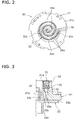
- a plurality of compression chambers 25a, 25b are formed between contact portions of the two wraps 21b, 22b, as shown in FIG.2 .
- the compression chamber 25a formed between an inner circumferential surface of the wrap 21b of the fixed scroll 21 and an outer circumferential surface of the wrap 22b of the movable scroll 22 is referred to as "a first compression chamber”
- the compression chamber 25b formed between an outer circumferential surface of the wrap 21b of the fixed scroll 21 and an inner circumferential surface of the movable side wrap 22b is referred to as "a second compression chamber”.
- a plurality of the first compression chambers 25a and the second compression chambers 25b are formed respectively. Further, in this embodiment, the number of turns of the wrap 21b is greater than the number of turns of the wrap 22b of the movable scroll 22. Thus, a maximum capacity of the first compression chamber 25a is larger than a maximum capacity of the second compression chamber 25b.
- an eccentric portion 42 of the crank shaft 40 is inserted into the bearing portion 22c via a sliding bearing 22d.
- the Oldham ring 24 is fitted into the groove portion 22e. Furthermore, the Oldham ring 24 is fitted into the Oldham grooves (not shown) formed in the housing 23, so that the movable scroll 22 is supported to the housing 23 via the Oldham ring 24.
- the movable scroll 22 orbits, without rotating, in the housing 23 around the shaft center of a main shaft portion 41as the center of its orbit due to the rotation of the crank shaft 40. Furthermore, the orbital radius of the movable scroll 22 is equal to an eccentric amount of the eccentric portion 42, that is, a distance from the shaft center of the main shaft portion 41 to the shaft center of the eccentric portion 42. And, in response to the orbital motion of the movable scroll 22, the volumes of the compression chambers 25a, 25b decrease as they move spirally inward toward the center of the orbit of the movable scroll 22. A gas refrigerant is, through this volume reduction arrangement, compressed in the high pressure dome-type scroll compressor 1 of this embodiment.
- the Oldham ring 24 is a member for preventing the movable scroll 22 from rotating, as described above, and is fitted into the Oldham grooves (not shown) formed in the housing 23. Furthermore, these Oldham grooves have an elliptical shape and are disposed at positions opposite to each other in the housing 23.
- the suction capacity regulating mechanism 30 is a mechanism for regulating the suction capacity by regulating shut-off positions of compression chambers 25a, 25b for suction in a suction step of the compression mechanism 20 (a position in which the suction step is completed and a compression step starts).
- the suction capacity regulating mechanism 30 is primarily composed of a communicating hole 32 formed in the end plate 21a of the fixed scroll 21, a gas refrigerant introducing pipe 50 whose inner space connects to the communicating hole 32, a lid body 27 which has an opening for receiving an end portion of the gas refrigerant introducing pipe 50 and supports the gas refrigerant introducing pipe 50 and covers an upper side of the communicating hole 32, a piston 33 inserted in the communicating hole 32, a compression coil spring 35 for biasing the piston 33 toward a side of the gas refrigerant introducing pipe, and a switching valve 36 for switching between "a condition of applying low pressure to the piston 33 through the gas refrigerant introducing pipe 50" and "a condition of applying high pressure to the piston 33 against a biasing force per unit area of the compression coil spring 35 through the gas refrigerant introducing pipe X".
- the piston 33 is primarily composed of a plug portion 33a having a size to fit in the small diameter hole portion 32b, a spring receiving portion 33b which has a diameter larger than that of the plug portion 33a and to which the compression coil spring 35 is attached on an outer circumferential surface, a seal attaching portion 33c having a diameter larger than that of the spring receiving portion 33b, an annular seal receiving groove 33d formed on an outer periphery of the seal attaching portion 33c, and a through hole 33f which opens at an upper end surface of the seal attaching portion 33c and a bottom surface of the seal receiving groove 33d.
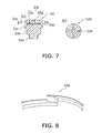
- a piston ring 33e made of synthetic resin is attached thereto, as shown in FIG.8 .
- a fitting end of this piston ring 33e has a step-like design as shown in FIG.8 , not a single right-angled fitting end.
- this piston 33 is movable between an opening position for opening the communicating hole 32 and a closing position for closing the communicating hole 32, via the compression coil spring 35 and the switching valve 36.
- the through hole 33f is, as shown in Fig. 7 , composed of a longitudinal hole 33g formed along a center shaft of the piston 33 and four lateral holes 33h, each of which extends radially from a lower end of the longitudinal hole to an outer circumferential surface of the piston 33.
- This suction capacity regulating mechanism 30 is able to switch between conditions of "communicate” and “shut-off” for the first compression chamber 25a and the second compression chamber 25b by means of the above-described configuration. Specifically, when a low pressure is applied to a rear end surface (upper end surface) of the piston 33 by the switching valve 36, a force exerted by the compression coil spring 35 to push up the piston 33 exceeds a force pushing down the piston 33. Accordingly, as shown in FIG.3 and FIG.9 , the above-described communicating hole 32 opens. As a result, a gap space SP is formed at a lower portion of the piston 33, so that the first compression chamber 25a and the second compression chamber 25b are in the "communicate" condition (refer to FIG.3 ).
- the refrigerant in the "communicate” condition, is compressed in the suction capacity to an extent less than the predetermined extent.
- a regulating operation an operation under this condition.
- a rotation speed of the drive motor 45 is faster than a rotation speed of the drive motor 45 under the normal operation.
- the drive motor 45 is a brushless DC motor capable of regulating a rotation speed variably by inverter control in this embodiment, and is primarily composed of an annular stator 46 secured to the inner wall surface of the casing 10, and a rotor 47 rotatably accommodated with a small gap (air gap channel) inside the stator 46.
- the drive motor 45 is disposed so that the upper end of a coil end 46a formed at the top side of the stator 46 is at substantially the same height as the lower end of the bearing portion 23c of the housing 23.
- a copper wire is wound around a tooth portion of the stator 46, and coil ends 46a are formed above and below the stator 46.
- the rotor 47 is connected to the movable scroll 22 of the scroll compression mechanism 20 via the crank shaft 40 disposed in the axial center of the trunk shell 11 so as to extend vertically.
- the crank shaft 40 is rotated in response to the rotation of this rotor 47.
- the crank shaft 40 is disposed in the axial center of the trunk shell 11 so as to extend vertically.
- This crank shaft 40 is primarily composed of a main shaft portion 41 and an eccentric portion 42.
- the eccentric portion 42 is formed so as to have a smaller diameter than that of the main shaft portion 41 and is formed on an upper end surface of the main shaft portion 41. And, this eccentric portion 42 is eccentric with respect to a shaft center of the main shaft portion 41 by a predetermined amount.
- an oil feed passage which extends vertically is formed. Further, in a lower end of the main shaft portion 41, an oil feed pump 43 is disposed. Through this oil feed pump 43, refrigerator oil is drawn up from a bottom portion of the casing 10. The refrigerator oil is supplied to sliding portions of the compression mechanism 20 and bearing portions for the crank shaft 40 through the oil feed passage of the crank shaft 40.
- the lower main bearing 48 is disposed in a lower space below the drive motor 45.
- the lower main bearing 45 is secured to the trunk shell 11 of the casing 10, and supports the lower end of the main shaft portion 41 of the crank shaft 40 rotatably via a sliding bearing 48a.
- the suction tube 14 is used for guiding the refrigerant of the refrigerant circuit to the scroll compression mechanism 15 and is provided in the fixed scroll 21 with an opening penetrating through the lid portion 12 of the casing 10.
- the discharge tube 15 is used for discharging the refrigerant inside the casing 10 to the outside of the casing 10, and is provided in the trunk shell 11 of the casing 10 with an opening penetrating through the trunk shell 11. An end portion of the discharge tube 15 is disposed so as to be located between the compression mechanism 20 and the drive motor 45 in the casing 10.
- each of the first compression chambers 25a and the second compression chambers 25b connects to the suction port 29 intermittently.
- each of the first compression chambers 25a and the second compression chambers 25b connects to the discharge passage 26 intermittently.
- the compressed refrigerant is discharged to the discharge space 28 through the discharge passage 26.
- the refrigerant discharged to the discharge space 28 then, flows into the high-pressure space 16 in a lower portion of the housing 23 through a gas passage which is not shown, and is supplied to the condenser of the refrigerant circuit from the discharge tube 15.
- the end of the wrap 22b of the movable scroll 22 is located between two turns of the wrap 21b of the fixed scroll 21.
- Both of the outermost first compression chamber 25a-0 and the outermost second compression chamber 25b-0 connect with the suction port 29 to be open to a low-pressure side.
- an outer circumferential surface of the movable side wrap 22b and an inner circumferential surface of the fixed side wrap 21b are substantially in contact with each other (note that "contact” used here means a condition in which a leak of the refrigerant does not matter because of an oil film formed in spite that a micron-order gap exists.).
- a first compression chamber 25a-1 located more spirally inward (the end of a scroll) than the contact position (seal point) P1 has already been in a compression step.
- the compression step of the second compression chamber 25b-1 and the suction step of the outermost first compression chamber 25a-0 further continue. Furthermore, at this time, a new second compression chamber 25b-0 is formed at an end of the wrap more spirally outward than the second compression chamber 25b-1, which is already in the middle of compression, and a suction step starts in the new second compression chamber.
- the suction step of the outermost second compression chamber 25b-0 continues and, on the other hand, the outer circumferential surface of the end of the wrap 22b of the movable scroll 22 is in contact with the inner circumferential surface of the wrap 21b of the fixed scroll 21.
- the contact point (seal point) P1 is the suction shut-off position of the first compression chamber 25b-1.
- a compression step of the first compression chamber 25a-1 formed in the fifth step proceeds, and the suction step of the outermost second compression chamber 25b-0 continues. And, when the movable scroll 22 further orbits clockwise, the step returns to the first step.
- a new first compression chamber 25a-0 is formed more spirally outward (the end of a scroll) than the first compression chamber 25a-1, which is in the middle of compression.
- the first compression chamber 25a-2 and the second compression chamber 25b-2 move to the innermost part of the spiral and their respective capacities reach a minimum, they are in contact with the discharge port 26. Thereafter, the refrigerant fully compressed in these two compression chambers 25a-2, 25b-2 is discharged from the compression mechanism 20.
- the end of the wrap 22b of the movable scroll 22 is located between two turns of the wrap 21 b of the fixed scroll 21.
- Both of the outermost first compression chamber 25a-0 and the outermost second compression chamber 25b-0 connect with the suction port 29 to be open to a low-pressure side.
- this first compression chamber 25a-1 is connected with the outermost second compression chamber 25b-0 which is in the middle of the suction step via the communicating hole 32. Therefore, the first compression chamber 25a-1 is still in a condition before the suction shut-off position is reached, and is in the middle of the same suction step as the second compression chamber 25b-0.
- the contact point P1 between the inner circumferential surface of the wrap 21b of the fixed scroll 21 and the outer circumferential surface of the wrap 22b of the movable scroll 22 is shifted to a position just after passing through the communicating hole 32. Therefore, the contact point (seal point) P1 at this time is the suction shut-off position of the first compression chamber 25a-1.
- the outermost second compression chamber 25b-1 to be shut off under the normal operation connects with the outermost first compression chamber 25a-0 formed at a scroll outer circumferential side of the first compression chamber 25a-1 turned to the compression step via the communicating hole 32.
- the second compression chamber 25b-1 is in a condition before the suction shut-off. Furthermore, this condition is similar to that in the third step (as shown in FIG. 13 ) and the fourth step (as shown in FIG.14 ).
- the third step the second compression chamber 25b-1 is in a condition before the suction shut-off. A seal point at the end of the wrap is not formed yet.
- the outermost first compression chamber 25a-0 is also in the middle of the suction step.
- a new second compression chamber 25b-0 starts being formed at the end of the scroll more spirally outward than the second compression chamber 25b-1.
- the contact point P2 between the outer circumferential surface of the wrap 21b of the fixed scroll 21 and the inner circumferential surface of the wrap 22b of the movable scroll 22 passes through the communicating hole 32. Therefore, the contact point P2 at this time is the seal point of the second compression chamber 25b-1.
- the compression step of the second compression chamber 25b-1 starts. Note that under the normal operation, in this step, the outermost first compression chamber 25a-1 is in a condition of shut-off. However, under the regulating operation, the outermost first compression chamber 25a-1 connects with the low-pressure side via the outermost second compression chamber 25b-0. Thus, the first compression chamber 25a-1 is still in the middle of the suction step. Furthermore, this condition is similar to that in the sixth step (as shown in FIG.16 ) and the first step (as shown in FIG.11 ).
- both suction capacities of the first compression chambers 25a and the second compression chambers 25b are smaller in comparison with them under the normal operation.
- the amount of gas in circulation is less than that under the normal operation, thereby resulting in a low-power operation.
- the rotation speed of the drive motor 45 is set so as to be faster than that under the normal operation.
- the seal receiving groove 33d and the through hole 33f are formed on the piston 33 in the suction capacity regulating mechanism 30. Further, the piston ring 33e having a step-like fitting end is fitted into the seal receiving groove 33d. Therefore, in this scroll compressor 1, when a gas refrigerant that applies a pressure larger than biasing force of the compression coil spring 35 for biasing the piston 33 per unit area is introduced into the gas refrigerant introducing pipe 50, the high-pressure gas refrigerant passes through the through hole 33f of the piston 33 and pushes the piston ring 33e against a wall of the through hole 33f. Then, the piston ring expands slightly at this time.
- the fitting end Since the fitting end has a step-like structure, it is able to suppress a leak of the high-pressure fluid effectively. Further, at the beginning of introducing the high-pressure gas refrigerant, the high-pressure gas refrigerant flows through a minute gap between the piston 33 and the communicating hole 32 of the fixed scroll 21. Thus, the piston ring 33e is pushed against a side of the compression chamber. Therefore, in this scroll compressor 1, when the high-pressure gas refrigerant that applies a pressure larger than biasing force of the compression coil spring 35 per unit area is introduced into the gas refrigerant introducing pipe 50, it is able to effectively suppress the high-pressure fluid flowing into compression chambers 25a, 25b. Therefore, in this scroll compressor 1, it is able to suppress a power reduction in the normal operation.
- the number of turns of the wrap 21 b of the fixed scroll 21 is about a half-turn greater than that of the wrap 22b of the movable scroll 22.
- the number of turns of the wrap 21 b of the fixed scroll 21 may be equal to the number of turns of the wrap 22b of the movable scroll 22.
- the operation is identical to examples of FIG. 11 to FIG.16 .
- the opening of the small diameter hole portion 32b of the communicating hole 32 is disposed at only one portion within one turn of the outer circumferential side of the scroll groove of the fixed scroll 21.
- openings of the communicating hole 32 may be disposed at plural locations. Further, in this case, plural communicating holes corresponding to the openings may be formed.
- the scroll compressor having the scroll compression mechanism 20 which combines the fixed scroll 21 with the movable scroll 22 is explained as one example.
- the present invention is applicable to a double-gear type scroll compressor or a scroll compressor in which both scroll members orbit.
- the communicating hole 32 formed in the fixed scroll 21 is composed of the large diameter hole portion 32a and the small diameter hole portion 32b.
- a communicating hole is not limited to such a design and may be formed in any appropriate shape.
- a high pressure dome-type scroll compressor 1 according to the second embodiment is the same as the high pressure dome-type scroll compressor 1 according to the first embodiment except for its suction capacity regulating mechanism. Therefore, hereinafter, only the suction capacity regulating mechanism is explained.
- a leak hole 132 which causes the low-pressure space 17 to connect to the small diameter hole portion 32b is disposed.
- the first compression chamber 25a and the second compression chamber 25b connect to each other and also, the first compression chamber 25a and the second compression chamber 25b connect to the low-pressure space 17.
- the first compression chamber 25a and the second compression chamber 25b are shut-off from each other and also, the first compression chamber 25a and the second compression chamber 25b are shut-off from the low-pressure space 17.
- the low-pressure space 17 and the small diameter hole portion 32b connect to each other through the leak hole 132.
- a leak hole may be formed so that a pipe of a suction side of the compression mechanism 20 and the small diameter hole portion 32b connect to each other.
- the leak hole may be formed so that the suction space and the small diameter hole portion 32b connect to each other.
- the communicating hole 32 and the leak hole 132 are formed so that, under the regulating operation, the first compression chamber 25a and the second compression chamber 25b connect to each other and also, the first compression chamber 25a and the second compression chamber 25b both connect to the low-pressure space 17.
- the communicating hole 32 and the leak hole 132 may be formed so that, under the regulating operation, only either the first compression chamber 25a or the second compression chamber 25b connects to the low-pressure space 17.
- the high pressure dome-type scroll compressor 1 according to the third embodiment is the same as the high pressure dome-type scroll compressor 1 according to the first embodiment except for its communicating hole. Therefore, hereinafter, only the communicating hole is explained.
- Two communicating holes 132a and 132b according to the third embodiment are formed as shown in FIG.19 .
- One of the communicating holes is formed for the first compression chamber 25a, and the other is formed for the second compression chamber 25b.
- the communicating hole referenced by a symbol 132a (hereinafter, referred to as "a first communicating hole") is for the first compression chamber 25a
- the communicating hole referenced by a symbol 132b (hereinafter, referred to as "a second communicating hole”) is for the second compression chamber 25b.
- these communicating holes 132a, 132b are holes independent from each other.
- openings of these communicating holes 132a, 132b have a circular arc shape as shown in FIG . 19 .
- the opening of the first communicating hole 132a extends along an inner circumferential surface of the wrap 21 b of the fixed scroll 21.
- the opening of the second communicating hole 132b extends along an outer circumferential surface of the wrap 21b of the fixed scroll 21.
- a suction capacity regulating mechanism is preferably similar to the suction capacity regulating mechanism 30 according to the first embodiment.
- a shape of the piston 33 needs to correspond to each communicating hole 132a, 132b.
- both of the compression chambers 25a, 25b are not shut-off until a contact point of wraps 21b and 22b passes through a position at which openings of the communicating holes 132a, 132b are located. That is, one of the first compression chamber 25a and the second compression chamber 25b is in a condition in which a portion of an inner circumferential side of the contact point connects with the suction side of the compression mechanism 20 via a portion of an outer circumferential side thereof, until the contact position passes through openings of the communicating holes 132a, 132b. A position just after the contact point passes through the openings of the communicating holes 132a, 132b is the suction shut-off point.
- the second compression chamber 25b-1 which would be shut-off under the normal operation is not shut-off under the regulating operation.
- the first compression chamber 25a-1 which would be shut-off under the normal operation is not shut-off under the regulating operation.
- the first communicating hole 132a for the first compression chamber 25a and the second communicating hole 132b for the second compression chamber 25b are disposed in the end plate of the fixed scroll.
- only the first communicating hole 132a for the first compression chamber 25a may be formed so as to decrease a suction capacity of only the first compression chamber 25a. By doing so, the difference of gas pressure between the first compression chamber 25a and the second compression chamber 25b can be decreased. Therefore, it is possible to reduce the effects of vibration due to imbalanced gas load or variation of a rotation torque of the scroll.
- balance of gas load has a relative relationship between the first compression chamber 25a and the second compression chamber 25b. Therefore, a regulating position of a suction capacity of the second compression chamber 25b may be shifted to a more spirally outward side (an end side) of a scroll than the regulating position of the suction capacity of the first compression chamber 25a so as to be able to regulate both of suction capacities of the first compression chamber 25a and the second compression chamber 25b.
- the scroll compressor according to the present invention has a characteristic that even if a fluid that applies a pressure larger than the biasing force of the biasing member per unit area is introduced into the fluid introducing pipe, it is able to effectively suppress the leak of high-pressure fluid into a compression chamber formed by the first scroll member and the second scroll member, and is available for a scroll compressor, especially for those scroll compressors that require a renewal.
Landscapes
- Engineering & Computer Science (AREA)
- Mechanical Engineering (AREA)
- General Engineering & Computer Science (AREA)
- Rotary Pumps (AREA)
- Applications Or Details Of Rotary Compressors (AREA)
Abstract
Description
- The present invention relates to a scroll compressor, and particularly to a scroll compressor capable of regulating its suction capacity.
- In the past, a technique has been introduced for providing a scroll compressor in which a suction capacity regulating mechanism is installed in an end plate of a fixed scroll (see
Patent Document 1, for example). - This suction capacity regulating mechanism is primarily composed of a through hole which penetrates through the end plate of the fixed scroll and opens at the bottom of a spiral groove of the fixed scroll, a fluid introducing passage which connects to the through hole, a piston which is inserted into the through hole, a biasing member which biases the piston toward a side of the fluid introducing passage in the through hole, and a metal piston ring which is fitted into an annular groove of the piston and which has a right-angled fitting end. The suction capacity regulating mechanism regulates a suction capacity of a scroll compressing mechanism by switching between a regulating operation condition involving a connection between "a first compression chamber formed between an inner circumferential surface of a wrap of the fixed scroll and an outer circumferential surface of a wrap of a movable scroll" and "a second compression chamber formed between an outer circumferential surface of the wrap of the fixed scroll and an inner circumferential surface of the wrap of the movable scroll" and a normal operation condition of shut-off between the first compression chamber and the second compression chamber (a condition that utilizes 100% of the suction capacity). Specifically, when a fluid that applies a pressure larger than biasing force of the biasing member per unit area is introduced into the fluid introducing passage, the piston is pushed down and a space at a lower end of the through hole is shut. The suction capacity regulating mechanism is turned to a condition of shut-off between the first compression chamber and the second compression chamber, that is, a normal operation condition. On the other hand, when a fluid that applies a pressure lower than biasing force of the biasing member per unit area is introduced into the fluid introducing passage, the piston is pushed up and the space at the lower end of the through hole is open. The suction capacity regulating mechanism is turned to a condition involving a connection between the first compression chamber and the second compression chamber, that is, a regulating operation condition.
<Patent Document 1>
Japanese Laid-open Patent Application No.2007-154761 - In the above suction capacity regulating mechanism, a minute gap exists between the through hole and the piston. Therefore, when a high-pressure fluid is introduced into the fluid introducing passage, the high-pressure fluid may undesirably flow into the compression chamber through the gap and the power of the scroll compressor under the normal operation may be reduced. In order to address this problem, in this suction capacity regulating mechanism, the metal piston ring which has a right-angled fitting end is fitted into the annular groove of the piston. This piston ring is tightly in contact with a wall surface of the through hole due to its resilient force so as to prevent the high-pressure fluid introduced into the fluid introducing passage from flowing into the compression chamber. However, in the metal piston ring having a right-angled fitting end, in a state that the piston ring is inserted into the through hole along with the piston, a slight gap exists at a part of the fitting end. Therefore, the above structure cannot perfectly prevent the high-pressure fluid introduced into the fluid introducing passage from flowing into the compression chamber.
- An object of the present invention is to further suppress the flow of high-pressure fluid from the fluid introducing passage into a compression chamber and to suppress a power reduction of the scroll compressor under a normal operation, in a scroll compressor in which a suction capacity regulating mechanism is installed in an end plate of a fixed scroll.
- A scroll compressor according to a first aspect of the present invention comprises a first scroll member, a second scroll member, a casing, a fluid introducing pipe, a piston, and a piston ring having a step-like fitting end. The first scroll member has a first flat plate part, a first spiral wall part, a fluid inlet, and a first through hole. The first spiral wall part extends from an eleventh plate surface of the first flat plate part toward a direction substantially perpendicular to the eleventh plate surface while keeping a spiral shape. The fluid inlet is formed near an end of the first spiral wall part. Note that this fluid inlet may be provided in the first flat plate part. The first through hole is formed in the eleventh plate surface and extends so as to penetrate through the first flat plate part from a first opening which opens at a part of the eleventh plate surface located at a position apart from the fluid inlet for a predetermined length. The first through hole is sandwiched between a most outer wall of the first spiral wall part and an inner circumferential wall which is opposite to the most outer wall. The second scroll member has a second flat plate part and a second spiral wall part. The second spiral wall part extends from a twenty-first plate surface of the second flat plate part toward a direction substantially perpendicular to the twenty-first plate surface while keeping a spiral shape. And, the second spiral wall part meshes with the first spiral wall part. The casing houses the first scroll member and the second scroll member. The fluid introducing pipe penetrates and extends through the casing from an opening formed at a side opposite to the first opening of the first through hole. And, an inner space of the fluid introducing pipe connects to the first through hole. The piston has an annular groove and a second through hole. The annular groove is formed on a side surface of the piston. The second through hole opens on an end surface of the piston at a side of the fluid introducing pipe and a bottom surface of the annular groove. Note that in the second through hole, the number or arrangement of openings which open at an end surface of the piston on the side of the fluid introducing pipe, as well as the number or arrangement of openings which open at the bottom surface of the annular groove, can be appropriately determined. Moreover, a cross-sectional area of the second through hole is preferably larger than a cross-sectional area of a gap between the piston and the first through hole. And, this piston is biased to a side of the fluid introducing pipe in the first through hole by a biasing member. This piston is configured so that the piston shuts the first opening when a fluid that applies a pressure larger than biasing force of the biasing member per unit area is introduced into the fluid introducing pipe and so that the piston forms a gap space on an upper part of the first opening when a fluid that applies a pressure smaller than the biasing force of the biasing member per unit area is introduced into the fluid introducing pipe. The piston ring having the step-like fitting end is fitted into the annular groove of the piston.
- In this scroll compressor, the annular groove and the second through hole are formed in the piston, and further, the piston ring having the step-like fitting end is fitted into the annular groove. Therefore, in this scroll compressor, when a fluid that applies a pressure larger than biasing force of the biasing member per unit area is introduced into the fluid introducing pipe and the first opening is shut by the piston, the high-pressure fluid passes through the second through hole of the piston and pushes the piston ring having the step-like fitting end against a wall of the second through hole. Note that the piston ring expands slightly at this time; however, since the fitting end has a step-like structure, a gap is not formed in the piston ring and it is able to avoid a leak of the high-pressure fluid effectively. Further, at this time, the high-pressure fluid flows through a minute gap between the piston and the second through hole. Thus, the piston ring is pushed against a side of the first opening. Therefore, in this scroll compressor, when a fluid that applies a pressure larger than biasing force of the biasing member per unit area is introduced into the fluid introducing pipe, it is able to effectively suppress the high-pressure fluid flowing into compression chambers formed by the first scroll member and the second scroll member. Therefore, in this scroll compressor, it is able to suppress a power reduction of the scroll compressor under a normal operation (at the time of an operation utilizing 100% of the suction capacity).
- A scroll compressor according to a second aspect of the present invention is the scroll compressor according to the first aspect of the present invention, wherein the first scroll member further has a third through hole which connects to the first through hole. Furthermore, the third through hole causes the first through hole to connect to a low-pressure space of the scroll compressor. And the piston shuts the first opening as well as an opening of a side of the piston in the second through hole when a fluid that applies a pressure larger than biasing force of the biasing member per unit area is introduced into the gas refrigerant introducing pipe. And, the piston connects the gap space and the second through hole when a fluid that applies a pressure smaller than the biasing force of the biasing member per unit area is introduced into the fluid introducing pipe.
- The scroll compressor according to the present invention, when a fluid that applies a pressure larger than biasing force of the biasing member per unit area is introduced into the fluid introducing pipe, is able to effectively suppress the flow of the high-pressure fluid into the compression chamber formed by the first scroll member and the second scroll member. Therefore, in this scroll compressor, a power reduction of the scroll compressor under a normal operation (at the time of an operation utilizing 100% of the suction capacity) can be suppressed.
-
-
FIG. 1 is a longitudinal sectional view of a scroll compressor according to the first embodiment. -
FIG. 2 is a cross-sectional view along the line II-II ofFIG. 1 . -
FIG. 3 is a longitudinal sectional view of a suction capacity regulating mechanism. -
FIG 4 is a bottom plane view of a fixed scroll. -
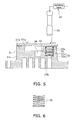
FIG 5 is a longitudinal sectional view showing a subassembly of the fixed scroll. -
FIG. 6 is a longitudinal sectional view of a compression coil spring for constituting the suction capacity regulating mechanism. -
FIG 7 (a) is a longitudinal sectional view of a piston for constituting the suction capacity regulating mechanism, andFIG. 7(b) is a cross-sectional view along the line III-III of the piston shown inFIG. 7 (a) . -
FIG. 8 is an exterior perspective view of a piston ring. -
FIG 9 is a longitudinal sectional view showing a condition of the piston under a regulating operation. -
FIG. 10 is a longitudinal sectional view showing a condition of the piston under a normal operation. -
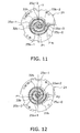
FIG. 11 is a transverse sectional view showing a condition in a first step of a compressing mechanism. -
FIG. 12 is a transverse sectional view showing a condition in a second step of the compressing mechanism. -
FIG. 13 is a transverse sectional view showing a condition in a third step of the compressing mechanism. -
FIG. 14 is a transverse sectional view showing a condition in a fourth step of the compressing mechanism. -
FIG. 15 is a transverse sectional view showing a condition in a fifth step of the compressing mechanism. -
FIG. 16 is a transverse sectional view showing a condition in a sixth step of the compressing mechanism. -
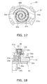
FIG 17 is a transverse sectional view of a compressing mechanism according to a variation of the first embodiment. -
FIG. 18 is a longitudinal sectional view of a suction capacity regulating mechanism according to the second embodiment. -
FIG 19 is a transverse sectional view showing a condition in a first step of a compressing mechanism according to the third embodiment. -
FIG 20 is a transverse sectional view showing a condition in a second step of the compressing mechanism according to the third embodiment. -
- 1
- scroll compressor
- 10
- casing
- 20
- compressing mechanism
- 21
- fixed scroll (first scroll member)
- 21a
- end plate
- 21b
- wrap
- 21 c
- edge portion (outmost wall)
- 22
- movable scroll (second scroll member)
- 22a
- end plate
- 22b
- wrap
- 29
- suction port (fluid inlet)
- 32
- communicating hole (first through hole)
- 33
- piston
- 33c
- annular groove
- 33e
- piston ring
- 33f
- through hole (second through hole)
- 35
- compression coil spring (biasing member)
- 50
- gas refrigerant introducing pipe (fluid introducing pipe)
- SP
- gap space
- The high pressure dome-
type scroll compressor 1 according to the first embodiment can be used together with an evaporator, a condenser, an expansion mechanism, and the like to constitute a refrigerant circuit. The high pressure dome-type scroll compressor 1 takes on a role of compressing a low pressure gas refrigerant in the refrigerant circuit so as to produce a high pressure gas refrigerant, and is primarily composed of a hermetically sealed dome-type casing 10, ascroll compression mechanism 20, a suctioncapacity regulating mechanism 30, adrive motor 45, acrank shaft 40, a lower main bearing 48, asuction tube 14, and adischarge tube 15, as shown inFIG. 1 . The constituent elements of the high pressure dome-type scroll compressor 1 will be respectively described in detail below. - The
casing 10 includes a substantiallycylindrical trunk shell 11, a bowl-shapedlid portion 12 which covers an upper end of thetrunk shell 11, and a bowl-shapedbottom portion 13 which covers a lower end of thetrunk shell 11. Furthermore, thetrunk shell 11 and thelid portion 12, as well as thetrunk shell 11 and thebottom portion 13, are welded in an airtight manner and thereby integrated so as to prevent a gas refrigerant from leaking. And, primarily accommodated in thecasing 10 are thescroll compression mechanism 20 for compressing a gas refrigerant, and thedrive motor 45 disposed below thescroll compression mechanism 20. Furthermore, thescroll compression mechanism 20 and thedrive motor 45 are connected by thecrank shaft 40 disposed so as to extend in the vertical direction inside thecasing 10. - The
scroll compression mechanism 20 is primarily composed of ahousing 23, a fixedscroll 21 provided in close contact above thehousing 23, amovable scroll 22 for meshing with the fixedscroll 21, and anOldham ring 24 for preventing themovable scroll 22 from rotating as shown inFIG. 1 . The constituent elements of thisscroll compression mechanism 20 will be respectively described in detail below. - The
housing 23 is constructed primarily with aflange part 23a, amain body part 23b, and a bearing part 23c. Themain body part 23b is designed to fit into thetrunk shell 11 of thecasing 10 and to couple with it. Theflange part 23a protrudes radially outward from themain body part 23b at an upper end of themain body part 23b. The bearing part 23c is formed so as to have a smaller diameter than that of themain body part 23b and protrudes downward from a lower surface of themain body part 23b. This bearing part 23c rotatably supports amain shaft part 41 of thecrank shaft 40 via aslide bearing 23d. - The fixed
scroll 21 is, as shown inFIG.1 , constructed primarily with anend plate 21a formed in a substantially disk-shape, a spiral (an involute-shaped)wrap 21b which is formed on a lower surface of theend plate 21a, and anedge portion 21 c. - A
discharge passage 26 that is in connection with a compression chamber formed by the fixedscroll 21 and themovable scroll 22, an enlargedconcave portion 21g that is in connection with thedischarge passage 26, and acommunication hole 32 which is needed to constitute the suctioncapacity regulating mechanism 30 are formed in theend plate 21 a. Thedischarge passage 26 is formed so as to extend in the vertical direction in a center portion of theend plate 21a. The enlargedconcave portion 21 g is formed from a concavity that is open on an upper surface of theend plate 21a. Alid body 27 is fastened and fixed on an upper surface of the fixedscroll 21 by a bolt (not shown) so as to close the opening of the enlargedconcave portion 21g. Thelid body 27 covers the enlargedconcave portion 21g, thereby forming adischarge space 28. Furthermore, theend plate 21a and thelid body 27 are sealed together by being firmly joined together via a packing which is not shown. Furthermore, a gas refrigerant discharged to the above-mentioneddischarge space 28 is introduced into a high-pressure space 16 in a lower portion of thehousing 23 through a gas passage (not shown) formed on the fixedscroll 21 and thehousing 23, and is then discharged from thedischarge tube 15 to the outside of thecasing 10. Further, in thecasing 10, a space in a lower portion of thehousing 23 corresponds to the high-pressure space 16, and a space in an upper portion of the housing (a space around the compressing mechanism 20) corresponds to a low-pressure space 17. The communicatinghole 32 is a hole which penetrates through theend plate 21 a along a direction of thickness of theend plate 21a, and comprises a largediameter hole portion 32a and a smalldiameter hole portion 32b. The largediameter hole portion 32a opens at an upper surface of theend plate 21a. The smalldiameter hole portion 32b opens at the bottom of aspiral groove 21g located at a location which is shifted spirally inward for a predetermined distance from an end of thespiral groove 21g of the fixedscroll 21. Note that the opening of this smalldiameter hole portion 32b at the bottom of thespiral groove 21g is a circular hole having a larger diameter than a thickness of thewrap 22b of themovable scroll 22. The suctioncapacity regulating mechanism 30 is described in detail below. - The number of turns of the
wrap 21b is about a half-turn greater than that of thewrap 22b of the movable scroll 22 (that is, it constitutes an asymmetrical spiral structure). However, the outmost turn of thiswrap 21b is not formed with an outer circumferential surface. This portion of thewrap 21b without the outer circumferential surface connects with theedge portion 21 c of the fixedscroll 21. And, the fixed side wrap 21 b ends in a way such that an end portion of an outer circumferential surface thereof and an end portion of an inner circumferential surface thereof, located at a location where thewrap 21 b continues for one more turn than the end portion of the outer circumferential side, face each other across thespiral groove 21g. An end portion of an outer circumferential surface (the end of the wrap) of themovable side wrap 22b is located near the end of the fixed side wrap 21 b. - The
edge portion 21c comprises a wall-like portion, which extends downward from an outer circumferential edge portion of theend plate 21a, and a flange-like portion, which protrudes radially outward from a lower end part of the wall-like portion and which is fastened to an upper surface of theflange part 23a of thehousing 23 by a bolt. - Further, in this fixed
scroll 21, asuction port 29 is formed near the end of thewrap 21b. And, thesuction tube 14 is fitted into thissuction port 29. Moreover, a check valve (not shown) is disposed in thissuction port 29. This check valve allows refrigerant to flow into the compression chamber formed by the fixedscroll 21 and themovable scroll 22 and shuts off a reverse flow of the refrigerant. - The
movable scroll 26 is, as shown inFIG. 1 , primarily composed of anend plate 22a, a spiral-shaped (an involute-shaped) wrap 22b formed on the upper surface of theend plate 22a, a bearingportion 22c formed on the lower surface of theend plate 22a, and agroove portion 22e formed in both ends of theend plate 22a. - The
end plate 22a is located in a firstconcave portion 23e disposed on an upper end surface of thehousing 23. - The bearing
portion 22c is located in a secondconcave portion 23f disposed in amain body portion 23b of thehousing 23. - The
wrap 22b is meshed with thewrap 21 b of the fixedscroll 21. As a result, a plurality ofcompression chambers wraps FIG.2 . Note that in this embodiment, for convenience of explanation, thecompression chamber 25a formed between an inner circumferential surface of thewrap 21b of the fixedscroll 21 and an outer circumferential surface of thewrap 22b of themovable scroll 22 is referred to as "a first compression chamber", and thecompression chamber 25b formed between an outer circumferential surface of thewrap 21b of the fixedscroll 21 and an inner circumferential surface of themovable side wrap 22b is referred to as "a second compression chamber". Furthermore, in thescroll compression mechanism 20, a plurality of thefirst compression chambers 25a and thesecond compression chambers 25b are formed respectively. Further, in this embodiment, the number of turns of thewrap 21b is greater than the number of turns of thewrap 22b of themovable scroll 22. Thus, a maximum capacity of thefirst compression chamber 25a is larger than a maximum capacity of thesecond compression chamber 25b. And, aneccentric portion 42 of thecrank shaft 40 is inserted into the bearingportion 22c via a slidingbearing 22d. TheOldham ring 24 is fitted into thegroove portion 22e. Furthermore, theOldham ring 24 is fitted into the Oldham grooves (not shown) formed in thehousing 23, so that themovable scroll 22 is supported to thehousing 23 via theOldham ring 24. And, by means of themovable scroll 22 being incorporated into thescroll compression mechanism 20 in this manner, themovable scroll 22 orbits, without rotating, in thehousing 23 around the shaft center of a main shaft portion 41as the center of its orbit due to the rotation of thecrank shaft 40. Furthermore, the orbital radius of themovable scroll 22 is equal to an eccentric amount of theeccentric portion 42, that is, a distance from the shaft center of themain shaft portion 41 to the shaft center of theeccentric portion 42. And, in response to the orbital motion of themovable scroll 22, the volumes of thecompression chambers movable scroll 22. A gas refrigerant is, through this volume reduction arrangement, compressed in the high pressure dome-type scroll compressor 1 of this embodiment. - The
Oldham ring 24 is a member for preventing themovable scroll 22 from rotating, as described above, and is fitted into the Oldham grooves (not shown) formed in thehousing 23. Furthermore, these Oldham grooves have an elliptical shape and are disposed at positions opposite to each other in thehousing 23. - The suction
capacity regulating mechanism 30 is a mechanism for regulating the suction capacity by regulating shut-off positions ofcompression chambers FIG.3 , the suctioncapacity regulating mechanism 30 is primarily composed of a communicatinghole 32 formed in theend plate 21a of the fixedscroll 21, a gasrefrigerant introducing pipe 50 whose inner space connects to the communicatinghole 32, alid body 27 which has an opening for receiving an end portion of the gasrefrigerant introducing pipe 50 and supports the gasrefrigerant introducing pipe 50 and covers an upper side of the communicatinghole 32, apiston 33 inserted in the communicatinghole 32, acompression coil spring 35 for biasing thepiston 33 toward a side of the gas refrigerant introducing pipe, and a switchingvalve 36 for switching between "a condition of applying low pressure to thepiston 33 through the gasrefrigerant introducing pipe 50" and "a condition of applying high pressure to thepiston 33 against a biasing force per unit area of thecompression coil spring 35 through the gas refrigerant introducing pipe X". - As shown in
FIG.7 , thepiston 33 is primarily composed of aplug portion 33a having a size to fit in the smalldiameter hole portion 32b, aspring receiving portion 33b which has a diameter larger than that of theplug portion 33a and to which thecompression coil spring 35 is attached on an outer circumferential surface, aseal attaching portion 33c having a diameter larger than that of thespring receiving portion 33b, an annularseal receiving groove 33d formed on an outer periphery of theseal attaching portion 33c, and a throughhole 33f which opens at an upper end surface of theseal attaching portion 33c and a bottom surface of theseal receiving groove 33d. Furthermore, in theseal receiving groove 33d, apiston ring 33e made of synthetic resin is attached thereto, as shown inFIG.8 . Further, a fitting end of thispiston ring 33e has a step-like design as shown inFIG.8 , not a single right-angled fitting end. And, thispiston 33 is movable between an opening position for opening the communicatinghole 32 and a closing position for closing the communicatinghole 32, via thecompression coil spring 35 and the switchingvalve 36. Further, the throughhole 33f is, as shown inFig. 7 , composed of alongitudinal hole 33g formed along a center shaft of thepiston 33 and fourlateral holes 33h, each of which extends radially from a lower end of the longitudinal hole to an outer circumferential surface of thepiston 33. - This suction
capacity regulating mechanism 30 is able to switch between conditions of "communicate" and "shut-off" for thefirst compression chamber 25a and thesecond compression chamber 25b by means of the above-described configuration. Specifically, when a low pressure is applied to a rear end surface (upper end surface) of thepiston 33 by the switchingvalve 36, a force exerted by thecompression coil spring 35 to push up thepiston 33 exceeds a force pushing down thepiston 33. Accordingly, as shown inFIG.3 andFIG.9 , the above-described communicatinghole 32 opens. As a result, a gap space SP is formed at a lower portion of thepiston 33, so that thefirst compression chamber 25a and thesecond compression chamber 25b are in the "communicate" condition (refer toFIG.3 ). On the other hand, when a high pressure is applied to a rear end surface of thepiston 33 by the switchingvalve 36, a force exerted by thecompression coil spring 35 to push down thepiston 33 exceeds a force by thecompression coil spring 35 to push up thepiston 33. Accordingly, as shown inFIG.10 , the communicatinghole 32 is shut, so that thefirst compression chamber 25a and thesecond compression chamber 25b are in the "shut-of' condition. Furthermore, in the "shut-off" condition, a refrigerant is compressed to a predetermined extent in a suction capacity. Note that hereinbelow, an operation under this condition is referred to as "a normal operation". Moreover, in the "communicate" condition, the refrigerant is compressed in the suction capacity to an extent less than the predetermined extent. Note that hereinbelow, an operation under this condition is referred to as "a regulating operation". Furthermore, in this embodiment, when the regulating operation is carried out, a rotation speed of thedrive motor 45 is faster than a rotation speed of thedrive motor 45 under the normal operation. - The
drive motor 45 is a brushless DC motor capable of regulating a rotation speed variably by inverter control in this embodiment, and is primarily composed of anannular stator 46 secured to the inner wall surface of thecasing 10, and arotor 47 rotatably accommodated with a small gap (air gap channel) inside thestator 46. Thedrive motor 45 is disposed so that the upper end of acoil end 46a formed at the top side of thestator 46 is at substantially the same height as the lower end of the bearing portion 23c of thehousing 23. - A copper wire is wound around a tooth portion of the
stator 46, and coil ends 46a are formed above and below thestator 46. - The
rotor 47 is connected to themovable scroll 22 of thescroll compression mechanism 20 via thecrank shaft 40 disposed in the axial center of thetrunk shell 11 so as to extend vertically. Thecrank shaft 40 is rotated in response to the rotation of thisrotor 47. - The
crank shaft 40 is disposed in the axial center of thetrunk shell 11 so as to extend vertically. This crankshaft 40 is primarily composed of amain shaft portion 41 and aneccentric portion 42. Theeccentric portion 42 is formed so as to have a smaller diameter than that of themain shaft portion 41 and is formed on an upper end surface of themain shaft portion 41. And, thiseccentric portion 42 is eccentric with respect to a shaft center of themain shaft portion 41 by a predetermined amount. - Furthermore, within the
crank shaft 40, an oil feed passage which extends vertically is formed. Further, in a lower end of themain shaft portion 41, anoil feed pump 43 is disposed. Through thisoil feed pump 43, refrigerator oil is drawn up from a bottom portion of thecasing 10. The refrigerator oil is supplied to sliding portions of thecompression mechanism 20 and bearing portions for thecrank shaft 40 through the oil feed passage of thecrank shaft 40. - The lower main bearing 48 is disposed in a lower space below the
drive motor 45. The lowermain bearing 45 is secured to thetrunk shell 11 of thecasing 10, and supports the lower end of themain shaft portion 41 of thecrank shaft 40 rotatably via a slidingbearing 48a. - The
suction tube 14 is used for guiding the refrigerant of the refrigerant circuit to thescroll compression mechanism 15 and is provided in the fixedscroll 21 with an opening penetrating through thelid portion 12 of thecasing 10. - The
discharge tube 15 is used for discharging the refrigerant inside thecasing 10 to the outside of thecasing 10, and is provided in thetrunk shell 11 of thecasing 10 with an opening penetrating through thetrunk shell 11. An end portion of thedischarge tube 15 is disposed so as to be located between thecompression mechanism 20 and thedrive motor 45 in thecasing 10. - When the
drive motor 45 is driven, thecrank shaft 40 rotates and themovable scroll 22 orbits with respect to the fixedscroll 21. At this time, themovable scroll 22 is prevented from rotating by theOldham ring 24. Along with the orbital motion of themovable scroll 22, volumes of thecompression chambers suction tube 14 to thecompression chambers suction port 29 when the volume of a portion connected to thesuction port 29 increases, and the refrigerant is compressed when the volume of a portion whose suction side is shut off decreases. Furthermore, along with the orbital motion of themovable scroll 22, each of thefirst compression chambers 25a and thesecond compression chambers 25b connects to thesuction port 29 intermittently. At the same time, each of thefirst compression chambers 25a and thesecond compression chambers 25b connects to thedischarge passage 26 intermittently. The compressed refrigerant is discharged to thedischarge space 28 through thedischarge passage 26. The refrigerant discharged to thedischarge space 28, then, flows into the high-pressure space 16 in a lower portion of thehousing 23 through a gas passage which is not shown, and is supplied to the condenser of the refrigerant circuit from thedischarge tube 15. - Here, refrigerant suction operation and refrigerant compression operation of the
compression mechanism 20 under normal operation are explained with reference toFIG. 11 to FIG.16 . Under the normal operation, thepiston 33 is located in a closing position, and the communicatinghole 32 is shut. Therefore, thefirst compression chambers 25a and thesecond compression chambers 25b are in the" shut-off" condition. Note that inFIG.11 to FIG.16 , operation conditions of thecompression mechanism 20 are shown in six separate steps. Furthermore, these figures represent a case in which themovable scroll 22 is orbiting clockwise with a predetermined angular gap. - Firstly, in the first step (as shown in
FIG.11 ), the end of thewrap 22b of themovable scroll 22 is located between two turns of thewrap 21b of the fixedscroll 21. Both of the outermostfirst compression chamber 25a-0 and the outermostsecond compression chamber 25b-0 connect with thesuction port 29 to be open to a low-pressure side. Furthermore, at a point P1 on a center line Y in the figure, an outer circumferential surface of themovable side wrap 22b and an inner circumferential surface of the fixedside wrap 21b are substantially in contact with each other (note that "contact" used here means a condition in which a leak of the refrigerant does not matter because of an oil film formed in spite that a micron-order gap exists.). Afirst compression chamber 25a-1 located more spirally inward (the end of a scroll) than the contact position (seal point) P1 has already been in a compression step. - When the
movable scroll 22 further orbits clockwise from the first step to enter the second step (as shown inFIG. 12 ), an inner circumferential surface of an end of thewrap 22b of themovable scroll 22 is in contact with an outer circumferential surface of thewrap 21b of the fixedscroll 21. The contact point (seal point) P2 is the suction shut-off position of thesecond compression chamber 25b-1. At this time, the outermostfirst compression chamber 25a-0 is in the middle of a suction step in which a capacity thereof increases. A seal point at the end of thisfirst compression chamber 25a-0 is not formed yet. - When the
movable scroll 22 further orbits clockwise from the second step to enter the third step (as shown inFIG. 13 ), the capacity of thesecond compression chamber 25b-1 decreases and compression step of refrigerant in thissecond compression chamber 25b-1 starts. The capacity of the outermostfirst compression chamber 25a-0 further increases and the suction step continues. - When the
movable scroll 22 further orbits clockwise from the third step to enter the fourth step (as shown inFIG.14 ), the compression step of thesecond compression chamber 25b-1 and the suction step of the outermostfirst compression chamber 25a-0 further continue. Furthermore, at this time, a newsecond compression chamber 25b-0 is formed at an end of the wrap more spirally outward than thesecond compression chamber 25b-1, which is already in the middle of compression, and a suction step starts in the new second compression chamber. - When the
movable scroll 22 further orbits clockwise from the fourth step to enter the fifth step (as shown inFIG.15 ), the suction step of the outermostsecond compression chamber 25b-0 continues and, on the other hand, the outer circumferential surface of the end of thewrap 22b of themovable scroll 22 is in contact with the inner circumferential surface of thewrap 21b of the fixedscroll 21. The contact point (seal point) P1 is the suction shut-off position of thefirst compression chamber 25b-1. - When the
movable scroll 22 further orbits clockwise from the fifth step to enter the sixth step (as shown inFIG. 16 ), a compression step of thefirst compression chamber 25a-1 formed in the fifth step proceeds, and the suction step of the outermostsecond compression chamber 25b-0 continues. And, when themovable scroll 22 further orbits clockwise, the step returns to the first step. A newfirst compression chamber 25a-0 is formed more spirally outward (the end of a scroll) than thefirst compression chamber 25a-1, which is in the middle of compression. And, when thefirst compression chamber 25a-2 and thesecond compression chamber 25b-2 move to the innermost part of the spiral and their respective capacities reach a minimum, they are in contact with thedischarge port 26. Thereafter, the refrigerant fully compressed in these twocompression chambers 25a-2, 25b-2 is discharged from thecompression mechanism 20. - Here, refrigerant suction operation and refrigerant compression operation of the
compression mechanism 20 under regulating operation are explained with reference toFIG.11 to FIG.16 in the same way as above. Under the regulating operation, thepiston 33 is in an opening position, and thesmall diameter portion 32b of the communicatinghole 32 is open. Therefore, thefirst compression chambers 25a and thesecond compression chambers 25b are in the "communicate" condition. - Firstly, in the first step (as shown in
FIG. 11 ), as is under the normal operation, the end of thewrap 22b of themovable scroll 22 is located between two turns of thewrap 21 b of the fixedscroll 21. Both of the outermostfirst compression chamber 25a-0 and the outermostsecond compression chamber 25b-0 connect with thesuction port 29 to be open to a low-pressure side. However, under the regulating operation, thisfirst compression chamber 25a-1 is connected with the outermostsecond compression chamber 25b-0 which is in the middle of the suction step via the communicatinghole 32. Therefore, thefirst compression chamber 25a-1 is still in a condition before the suction shut-off position is reached, and is in the middle of the same suction step as thesecond compression chamber 25b-0. - When the
movable scroll 22 orbits clockwise from the first step to enter the second step (as shown inFIG.12 ), the contact point P1 between the inner circumferential surface of thewrap 21b of the fixedscroll 21 and the outer circumferential surface of thewrap 22b of themovable scroll 22 is shifted to a position just after passing through the communicatinghole 32. Therefore, the contact point (seal point) P1 at this time is the suction shut-off position of thefirst compression chamber 25a-1. On the other hand, under this condition, the outermostsecond compression chamber 25b-1 to be shut off under the normal operation connects with the outermostfirst compression chamber 25a-0 formed at a scroll outer circumferential side of thefirst compression chamber 25a-1 turned to the compression step via the communicatinghole 32. And, as this outermostfirst compression chamber 25a-0 is in the middle of the suction step, thesecond compression chamber 25b-1 is in a condition before the suction shut-off. Furthermore, this condition is similar to that in the third step (as shown inFIG. 13 ) and the fourth step (as shown inFIG.14 ). In the third step, thesecond compression chamber 25b-1 is in a condition before the suction shut-off. A seal point at the end of the wrap is not formed yet. Further, at this time, the outermostfirst compression chamber 25a-0 is also in the middle of the suction step. Furthermore, in the fourth step, a newsecond compression chamber 25b-0 starts being formed at the end of the scroll more spirally outward than thesecond compression chamber 25b-1. - When the
movable scroll 22 further orbits clockwise from the fourth step to enter the fifth step (as shown inFIG.15 ), the contact point P2 between the outer circumferential surface of thewrap 21b of the fixedscroll 21 and the inner circumferential surface of thewrap 22b of themovable scroll 22 passes through the communicatinghole 32. Therefore, the contact point P2 at this time is the seal point of thesecond compression chamber 25b-1. The compression step of thesecond compression chamber 25b-1 starts. Note that under the normal operation, in this step, the outermostfirst compression chamber 25a-1 is in a condition of shut-off. However, under the regulating operation, the outermostfirst compression chamber 25a-1 connects with the low-pressure side via the outermostsecond compression chamber 25b-0. Thus, thefirst compression chamber 25a-1 is still in the middle of the suction step. Furthermore, this condition is similar to that in the sixth step (as shown inFIG.16 ) and the first step (as shown inFIG.11 ). - As such, when the communicating
hole 32 is open, both suction capacities of thefirst compression chambers 25a and thesecond compression chambers 25b are smaller in comparison with them under the normal operation. As a result, under the regulating operation, the amount of gas in circulation is less than that under the normal operation, thereby resulting in a low-power operation. Furthermore, in this embodiment, when the regulating operation is carried out, the rotation speed of thedrive motor 45 is set so as to be faster than that under the normal operation. Thus, a power under the regulating operation can be maintained so as to be equal to the power under the normal operation. - In the high pressure dome-
type scroll compressor 1 according to this embodiment, theseal receiving groove 33d and the throughhole 33f are formed on thepiston 33 in the suctioncapacity regulating mechanism 30. Further, thepiston ring 33e having a step-like fitting end is fitted into theseal receiving groove 33d. Therefore, in thisscroll compressor 1, when a gas refrigerant that applies a pressure larger than biasing force of thecompression coil spring 35 for biasing thepiston 33 per unit area is introduced into the gasrefrigerant introducing pipe 50, the high-pressure gas refrigerant passes through the throughhole 33f of thepiston 33 and pushes thepiston ring 33e against a wall of the throughhole 33f. Then, the piston ring expands slightly at this time. Since the fitting end has a step-like structure, it is able to suppress a leak of the high-pressure fluid effectively. Further, at the beginning of introducing the high-pressure gas refrigerant, the high-pressure gas refrigerant flows through a minute gap between thepiston 33 and the communicatinghole 32 of the fixedscroll 21. Thus, thepiston ring 33e is pushed against a side of the compression chamber. Therefore, in thisscroll compressor 1, when the high-pressure gas refrigerant that applies a pressure larger than biasing force of thecompression coil spring 35 per unit area is introduced into the gasrefrigerant introducing pipe 50, it is able to effectively suppress the high-pressure fluid flowing intocompression chambers scroll compressor 1, it is able to suppress a power reduction in the normal operation. - In the high pressure dome-
type scroll compressor 1 according to the first embodiment, the number of turns of thewrap 21 b of the fixedscroll 21 is about a half-turn greater than that of thewrap 22b of themovable scroll 22. However, as shown inFIG.17 , the number of turns of thewrap 21 b of the fixedscroll 21 may be equal to the number of turns of thewrap 22b of themovable scroll 22. Furthermore, in this case, the operation is identical to examples ofFIG. 11 to FIG.16 . - In the high pressure dome-
type scroll compressor 1 according to the first embodiment, the opening of the smalldiameter hole portion 32b of the communicatinghole 32 is disposed at only one portion within one turn of the outer circumferential side of the scroll groove of the fixedscroll 21. However, openings of the communicatinghole 32 may be disposed at plural locations. Further, in this case, plural communicating holes corresponding to the openings may be formed. By doing so, the scroll compressor is able to regulate the suction capacity of thecompression mechanism 20 in a step-by-step manner. Therefore, it is possible to carry out finer control according to an operation condition of the refrigerant circuit. - In the first embodiment, the scroll compressor having the
scroll compression mechanism 20 which combines the fixedscroll 21 with themovable scroll 22, is explained as one example. However, the present invention is applicable to a double-gear type scroll compressor or a scroll compressor in which both scroll members orbit. - In the high pressure dome-
type scroll compressor 1 according to the first embodiment, the communicatinghole 32 formed in the fixedscroll 21 is composed of the largediameter hole portion 32a and the smalldiameter hole portion 32b. However, a communicating hole is not limited to such a design and may be formed in any appropriate shape. - A high pressure dome-
type scroll compressor 1 according to the second embodiment is the same as the high pressure dome-type scroll compressor 1 according to the first embodiment except for its suction capacity regulating mechanism. Therefore, hereinafter, only the suction capacity regulating mechanism is explained. - In a suction
capacity regulating mechanism 130 according to the second embodiment, in addition to the constituent elements of the suctioncapacity regulating mechanism 30 according to the first embodiment, aleak hole 132 which causes the low-pressure space 17 to connect to the smalldiameter hole portion 32b is disposed. In this embodiment, with such structure of the suctioncapacity regulating mechanism 130, under the regulating operation, thefirst compression chamber 25a and thesecond compression chamber 25b connect to each other and also, thefirst compression chamber 25a and thesecond compression chamber 25b connect to the low-pressure space 17. Furthermore, under the normal operation, thefirst compression chamber 25a and thesecond compression chamber 25b are shut-off from each other and also, thefirst compression chamber 25a and thesecond compression chamber 25b are shut-off from the low-pressure space 17. - In the high pressure dome-
type scroll compressor 1 according to the second embodiment, the low-pressure space 17 and the smalldiameter hole portion 32b connect to each other through theleak hole 132. However, a leak hole may be formed so that a pipe of a suction side of thecompression mechanism 20 and the smalldiameter hole portion 32b connect to each other. And further, if a suction space is provided, the leak hole may be formed so that the suction space and the smalldiameter hole portion 32b connect to each other. - In the high pressure dome-
type scroll compressor 1 according to the second embodiment, the communicatinghole 32 and theleak hole 132 are formed so that, under the regulating operation, thefirst compression chamber 25a and thesecond compression chamber 25b connect to each other and also, thefirst compression chamber 25a and thesecond compression chamber 25b both connect to the low-pressure space 17. However, the communicatinghole 32 and theleak hole 132 may be formed so that, under the regulating operation, only either thefirst compression chamber 25a or thesecond compression chamber 25b connects to the low-pressure space 17. - The high pressure dome-
type scroll compressor 1 according to the third embodiment is the same as the high pressure dome-type scroll compressor 1 according to the first embodiment except for its communicating hole. Therefore, hereinafter, only the communicating hole is explained. - Two communicating
holes FIG.19 . One of the communicating holes is formed for thefirst compression chamber 25a, and the other is formed for thesecond compression chamber 25b. Furthermore, here, the communicating hole referenced by asymbol 132a (hereinafter, referred to as "a first communicating hole") is for thefirst compression chamber 25a, and the communicating hole referenced by asymbol 132b (hereinafter, referred to as "a second communicating hole") is for thesecond compression chamber 25b. Further, in this embodiment, these communicatingholes holes FIG.19 . The opening of the first communicatinghole 132a extends along an inner circumferential surface of thewrap 21 b of the fixedscroll 21. The opening of the second communicatinghole 132b extends along an outer circumferential surface of thewrap 21b of the fixedscroll 21. - In this case, a suction capacity regulating mechanism is preferably similar to the suction
capacity regulating mechanism 30 according to the first embodiment. However, a shape of thepiston 33 needs to correspond to each communicatinghole - In this embodiment, under the normal operation, as similar to the first embodiment and the second embodiment, a point at which the
wraps first compression chamber 25a and thesecond compression chamber 25b are formed. - On the other hand, under the regulating operation, both of the
compression chambers wraps holes first compression chamber 25a and thesecond compression chamber 25b is in a condition in which a portion of an inner circumferential side of the contact point connects with the suction side of thecompression mechanism 20 via a portion of an outer circumferential side thereof, until the contact position passes through openings of the communicatingholes holes FIG.20 , in a step shown inFIG.19 , thesecond compression chamber 25b-1 which would be shut-off under the normal operation, is not shut-off under the regulating operation. Further, in a step shown inFIG.20 , similar to the step shown inFIG.19 , thefirst compression chamber 25a-1 which would be shut-off under the normal operation, is not shut-off under the regulating operation. - Therefore, the size of a suction capacity can be regulated even in a scroll compressor according to this embodiment.
- In the scroll compressor according to the third embodiment, the first communicating
hole 132a for thefirst compression chamber 25a and the second communicatinghole 132b for thesecond compression chamber 25b are disposed in the end plate of the fixed scroll. However, only the first communicatinghole 132a for thefirst compression chamber 25a may be formed so as to decrease a suction capacity of only thefirst compression chamber 25a. By doing so, the difference of gas pressure between thefirst compression chamber 25a and thesecond compression chamber 25b can be decreased. Therefore, it is possible to reduce the effects of vibration due to imbalanced gas load or variation of a rotation torque of the scroll. - While not referred to specifically in the third embodiment, balance of gas load has a relative relationship between the
first compression chamber 25a and thesecond compression chamber 25b. Therefore, a regulating position of a suction capacity of thesecond compression chamber 25b may be shifted to a more spirally outward side (an end side) of a scroll than the regulating position of the suction capacity of thefirst compression chamber 25a so as to be able to regulate both of suction capacities of thefirst compression chamber 25a and thesecond compression chamber 25b. - The scroll compressor according to the present invention has a characteristic that even if a fluid that applies a pressure larger than the biasing force of the biasing member per unit area is introduced into the fluid introducing pipe, it is able to effectively suppress the leak of high-pressure fluid into a compression chamber formed by the first scroll member and the second scroll member, and is available for a scroll compressor, especially for those scroll compressors that require a renewal.
Claims (2)
- A scroll compressor (1) comprising:a first scroll member (21) having a first flat plate part (21 a), a first spiral wall part (21b) configured to extend from an eleventh plate surface of the first flat plate part (21a) toward a direction substantially perpendicular to the eleventh plate surface while keeping a spiral shape, a fluid inlet (29) formed near an end of the first spiral wall part (21b), a first through hole (32) formed in the eleventh plate surface and configured to extend so as to penetrate the first flat plate part from a first opening which opens at a part of the eleventh plate surface located at a position apart from the fluid inlet for a predetermined length, the first through hole (32) being sandwiched between a most outer wall (21c) of the first spiral wall part and an inner circumferential wall arranged to be opposite to the most outer wall;a second scroll member (22) having a second flat plate part (22a), and a second spiral wall part (22b) configured to extend from a twenty-first plate surface of the second flat plate part (22a) toward a direction substantially perpendicular to the twenty-first plate surface while keeping a spiral shape and configured to mesh with the first spiral wall part;a casing (10) configured to house the first scroll member and the second scroll member;a fluid introducing pipe (50) configured to penetrate and extend through the casing from an opening formed at a side opposite to the first opening of the first through hole and whose inner space is configured to connect to the first through hole;a piston (33) configured to be biased to a side of the fluid introducing pipe in the first through hole by a biasing member (35) and having an annular groove (33d) formed on a side surface of the piston and a second through hole (33f) opening on an end surface of a side of the fluid introducing pipe and a bottom surface of the annular groove, and configured such that the piston shuts the first opening when a fluid that applies a pressure larger than biasing force of the biasing member per unit area is introduced into the fluid introducing pipe and such that the piston forms a gap space (SP) on an upper part of the first opening when a fluid that applies a pressure smaller than the biasing force of the biasing member per unit area is introduced into the fluid introducing pipe; anda piston ring (33e) configured to be fitted into the annular groove of the piston and having a step-like fitting end.
- The scroll compressor according to claim 1, wherein
the first scroll member further has a third through hole (132) configured to connect to the first through hole; and wherein
the piston shuts the first opening as well as an opening of a side of the piston in the third through hole when a fluid that applies a pressure larger than biasing force of the biasing member per unit area is introduced into the fluid introducing pipe, and the piston connects the gap space and the third through hole when a fluid that applies a pressure smaller than the biasing force of the biasing member per unit area is introduced into the fluid introducing pipe.
Applications Claiming Priority (2)
| Application Number | Priority Date | Filing Date | Title |
|---|---|---|---|
| JP2007193277A JP2009030469A (en) | 2007-07-25 | 2007-07-25 | Scroll compressor |
| PCT/JP2008/063146 WO2009014128A1 (en) | 2007-07-25 | 2008-07-23 | Scroll compressor |
Publications (2)
| Publication Number | Publication Date |
|---|---|
| EP2177763A1 true EP2177763A1 (en) | 2010-04-21 |
| EP2177763A4 EP2177763A4 (en) | 2014-10-29 |
Family
ID=40281379
Family Applications (1)
| Application Number | Title | Priority Date | Filing Date |
|---|---|---|---|
| EP08791427.1A Withdrawn EP2177763A4 (en) | 2007-07-25 | 2008-07-23 | SPIRAL COMPRESSOR |
Country Status (5)
| Country | Link |
|---|---|
| US (1) | US8622723B2 (en) |
| EP (1) | EP2177763A4 (en) |
| JP (1) | JP2009030469A (en) |
| CN (1) | CN101772646A (en) |
| WO (1) | WO2009014128A1 (en) |
Families Citing this family (12)
| Publication number | Priority date | Publication date | Assignee | Title |
|---|---|---|---|---|
| JP5357800B2 (en) | 2009-02-12 | 2013-12-04 | キヤノン株式会社 | Electronic device and control method thereof |
| US20150004039A1 (en) * | 2013-06-28 | 2015-01-01 | Emerson Climate Technologies, Inc. | Capacity-modulated scroll compressor |
| CN104912795B (en) * | 2014-03-10 | 2017-06-30 | 珠海格力节能环保制冷技术研究中心有限公司 | Varying capacity screw compressor |
| CN105317675B (en) * | 2014-06-30 | 2017-11-14 | 珠海格力节能环保制冷技术研究中心有限公司 | Varying capacity screw compressor |
| US20160017894A1 (en) * | 2014-07-15 | 2016-01-21 | Borgwarner Inc. | Coolant pump with heat sinking to coolant |
| DE102015207909A1 (en) * | 2015-04-29 | 2016-11-03 | Mahle International Gmbh | axial piston |
| CN105275804B (en) * | 2015-10-15 | 2017-10-10 | 珠海格力节能环保制冷技术研究中心有限公司 | The displacement-variable device and screw compressor of screw compressor |
| WO2019138553A1 (en) * | 2018-01-12 | 2019-07-18 | 日立ジョンソンコントロールズ空調株式会社 | Scroll compressor |
| CN114222862B (en) * | 2019-08-30 | 2023-07-25 | 大金工业株式会社 | scroll compressor |
| WO2021088467A1 (en) * | 2019-11-04 | 2021-05-14 | 艾默生环境优化技术(苏州)有限公司 | Scroll compressor |
| CN113007093B (en) * | 2019-12-20 | 2023-12-22 | 谷轮环境科技(苏州)有限公司 | Scroll compressor having a rotor with a rotor shaft having a rotor shaft with a |
| KR20220015237A (en) * | 2020-07-30 | 2022-02-08 | 엘지전자 주식회사 | Scroll compressor |
Family Cites Families (14)
| Publication number | Priority date | Publication date | Assignee | Title |
|---|---|---|---|---|
| JPS5743369U (en) | 1980-08-22 | 1982-03-09 | ||
| JPH0361681A (en) | 1989-04-07 | 1991-03-18 | Fuji Electric Co Ltd | Compressor for refrigerator |
| JPH03189382A (en) * | 1989-12-19 | 1991-08-19 | Tokico Ltd | reciprocating compressor |
| JP2890174B2 (en) * | 1995-03-31 | 1999-05-10 | 東京瓦斯株式会社 | Piston for high pressure gas compressor |
| JPH1037857A (en) | 1996-07-23 | 1998-02-13 | Tokico Ltd | Reciprocating compressor |
| JP3874469B2 (en) * | 1996-10-04 | 2007-01-31 | 株式会社日立製作所 | Scroll compressor |
| US6138923A (en) * | 1997-03-25 | 2000-10-31 | Isuzu Motors Limited | Injector |
| US6146119A (en) * | 1997-11-18 | 2000-11-14 | Carrier Corporation | Pressure actuated seal |
| JP4193333B2 (en) * | 2000-06-02 | 2008-12-10 | 株式会社Inax | Single shaft type valve |
| KR100557057B1 (en) * | 2003-07-26 | 2006-03-03 | 엘지전자 주식회사 | Scroll compressor with volume regulating capability |
| KR100664058B1 (en) * | 2004-11-04 | 2007-01-03 | 엘지전자 주식회사 | Variable Capacity of Scroll Compressor |
| JP4488222B2 (en) * | 2005-05-20 | 2010-06-23 | 株式会社富士通ゼネラル | Scroll compressor |
| JP2007154761A (en) | 2005-12-05 | 2007-06-21 | Daikin Ind Ltd | Scroll compressor |
| JP2007154762A (en) | 2005-12-05 | 2007-06-21 | Daikin Ind Ltd | Scroll compressor |
-
2007
- 2007-07-25 JP JP2007193277A patent/JP2009030469A/en active Pending
-
2008
- 2008-07-23 EP EP08791427.1A patent/EP2177763A4/en not_active Withdrawn
- 2008-07-23 US US12/669,240 patent/US8622723B2/en not_active Expired - Fee Related
- 2008-07-23 WO PCT/JP2008/063146 patent/WO2009014128A1/en not_active Ceased
- 2008-07-23 CN CN200880100335A patent/CN101772646A/en active Pending
Also Published As
| Publication number | Publication date |
|---|---|
| WO2009014128A1 (en) | 2009-01-29 |
| US8622723B2 (en) | 2014-01-07 |
| JP2009030469A (en) | 2009-02-12 |
| US20100189585A1 (en) | 2010-07-29 |
| EP2177763A4 (en) | 2014-10-29 |
| CN101772646A (en) | 2010-07-07 |
Similar Documents
| Publication | Publication Date | Title |
|---|---|---|
| US8622723B2 (en) | Scroll compressor | |
| US8517703B2 (en) | Compressor including valve assembly | |
| US9267501B2 (en) | Compressor including biasing passage located relative to bypass porting | |
| US10718330B2 (en) | Co-rotating compressor with multiple compression mechanisms | |
| US9651044B2 (en) | Electric compressor | |
| US9441630B2 (en) | Horizontal type scroll compressor having discharge guide between a main scroll and a motor housing | |
| US11293442B2 (en) | Scroll compressor having discharge cover providing a space to guide a discharge flow from a discharge port to a discharge passgae formed by a plurality of discharge holes | |
| WO2014178189A1 (en) | Scroll compressor | |
| JP6555543B2 (en) | Scroll compressor | |
| CN108779774A (en) | Scroll compressor | |
| EP3415764B1 (en) | Scroll compressor | |
| CN104105881B (en) | scroll compressor | |
| US20130219950A1 (en) | Scroll Compressor and Air Conditioner | |
| JP4844642B2 (en) | Scroll compressor | |
| US11988206B2 (en) | Scroll compressor with grooves and auxiliary discharge ports | |
| JP7764806B2 (en) | Scroll type electric compressor | |
| JP2020045778A (en) | Compressor | |
| JP4604968B2 (en) | Scroll compressor | |
| JP4301122B2 (en) | Scroll compressor | |
| US20250297608A1 (en) | Scroll compressor | |
| JP4301120B2 (en) | Scroll compressor | |
| JP2011127462A (en) | Compressor | |
| JP2006336543A (en) | Scroll compressor | |
| EP3992461B1 (en) | Scroll compressor | |
| WO2018021058A1 (en) | Scroll compressor |
Legal Events
| Date | Code | Title | Description |
|---|---|---|---|
| PUAI | Public reference made under article 153(3) epc to a published international application that has entered the european phase |
Free format text: ORIGINAL CODE: 0009012 |
|
| 17P | Request for examination filed |
Effective date: 20100122 |
|
| AK | Designated contracting states |
Kind code of ref document: A1 Designated state(s): AT BE BG CH CY CZ DE DK EE ES FI FR GB GR HR HU IE IS IT LI LT LU LV MC MT NL NO PL PT RO SE SI SK TR |
|
| AX | Request for extension of the european patent |
Extension state: AL BA MK RS |
|
| DAX | Request for extension of the european patent (deleted) | ||
| A4 | Supplementary search report drawn up and despatched |
Effective date: 20140929 |
|
| RIC1 | Information provided on ipc code assigned before grant |
Ipc: F04C 18/02 20060101AFI20140923BHEP |
|
| STAA | Information on the status of an ep patent application or granted ep patent |
Free format text: STATUS: REQUEST FOR EXAMINATION WAS MADE |
|
| STAA | Information on the status of an ep patent application or granted ep patent |
Free format text: STATUS: THE APPLICATION IS DEEMED TO BE WITHDRAWN |
|
| 18D | Application deemed to be withdrawn |
Effective date: 20180201 |