EP2177733A1 - Controlled nucleate boiling sensor - Google Patents
Controlled nucleate boiling sensor Download PDFInfo
- Publication number
- EP2177733A1 EP2177733A1 EP08166816A EP08166816A EP2177733A1 EP 2177733 A1 EP2177733 A1 EP 2177733A1 EP 08166816 A EP08166816 A EP 08166816A EP 08166816 A EP08166816 A EP 08166816A EP 2177733 A1 EP2177733 A1 EP 2177733A1
- Authority
- EP
- European Patent Office
- Prior art keywords
- sensor
- nucleate boiling
- controlled
- cavity
- zone
- Prior art date
- Legal status (The legal status is an assumption and is not a legal conclusion. Google has not performed a legal analysis and makes no representation as to the accuracy of the status listed.)
- Withdrawn
Links
Images



Classifications
-
- F—MECHANICAL ENGINEERING; LIGHTING; HEATING; WEAPONS; BLASTING
- F01—MACHINES OR ENGINES IN GENERAL; ENGINE PLANTS IN GENERAL; STEAM ENGINES
- F01P—COOLING OF MACHINES OR ENGINES IN GENERAL; COOLING OF INTERNAL-COMBUSTION ENGINES
- F01P11/00—Component parts, details, or accessories not provided for in, or of interest apart from, groups F01P1/00 - F01P9/00
- F01P11/14—Indicating devices; Other safety devices
- F01P11/16—Indicating devices; Other safety devices concerning coolant temperature
Definitions
- This patent disclosure relates generally to a temperature measurement arrangement of a cooling circuit and a related method in which a sensing device may monitor a surface temperature in a cooling circuit, detect nucleate boiling or control the boiling state of a liquid coolant circulating in the cooling circuit.
- This patent disclosure relates generally to the field of cooling systems for high-temperature generating apparatuses, such as vehicle engines, and to the field of low pressure, low temperature boiling systems, for instance in air conditioning (HVAC) and heating ventilation systems.
- HVAC air conditioning
- the engine may be kept in operative mode by using a cooling circuit wherein a liquid coolant circulates inside the cooling circuit.
- a liquid coolant circulating inside the cooling circuit may transport the heat away from a heat source in order to prevent overheating of the engine.
- thermal exchange may be increased by providing cavities in a surface of the cooling system in contact with the liquid coolant. At a certain wall superheat temperature, bubbles may form and depart from the cavities and transport the heat away from the surface of the cooling system.
- the cooling system may be influenced to alter the rate of nucleate boiling. This may be done by activation of external ventilation units to reduce coolant temperature, increasing the speed of the coolant flow for transporting the heat away from the heat source, or any other suitable procedures to alter the boiling state .
- a sensor may be used to measure the temperature of the cooling circuit wall to detect bubble departure. In case a measured temperature exceeds a pre-defined alerting value, measures could be taken to prevent any damage to the cooling system, including derating or stopping the engine until it has cooled down or activating additional cooling systems, e.g. a fan unit, for providing further cooling.
- additional cooling systems e.g. a fan unit
- known sensor arrangements may provide temperature indication, they may not measure the temperature accurately, may not provide information quickly enough or measure the temperature at a suitable location to fully control a nucleate boiling state.
- nucleate boiling sensor arrangement which is adapted to react quickly, preferably in real-time, to keep a liquid coolant in a nucleation boiling state
- This patent disclosure relates generally to a nucleate boiling sensor arrangement for liquid cooling systems, comprising a sensor positioned in a support structure; and at least one nucleation cavity in a support structure, said nucleation cavity having a zone of bubble formation, a portion of the sensor positioned at the zone of bubble formation so as to detect initiation of a nucleate boiling state.
- a method of measuring a nucleate boiling temperature of a surface having at least one nucleation cavity in liquid cooling systems comprising the steps of positioning a portion of a sensor at a zone of bubble formation of at least one cavity and monitoring a temperature at said zone of bubble formation to detect initiation of nucleate boiling state.
- the disclosure describes a nucleate boiling sensor arrangement adapted to measure a temperature of said liquid coolant in a same plane spanned by said surface.
- This disclosure generally relates to a controlled nucleate boiling sensor arrangement for liquid cooling systems. Particularly, it relates to a sensor arrangement and process for accurate detection of initiation of a nucleate boiling state and monitoring thereof.
- Fig. 1 illustrates a cavity 12 which may be located in a liquid cooling system for instance in a cooling circuit of a vehicle.
- Cavity 12 may be formed within a support structure 18 of the cooling circuit.
- bubbles may form in cavity 12 and depart therefrom.
- a bubble may form within a zone of bubble formation 13 prior to bubble departure.
- the zone of bubble formation 13 includes the hollow of the cavity 12 and the proximate region around the aperture of cavity 12 on surface 11. In the absence of a bubble said areas may be in contact with a coolant liquid that may circulate through the coolant circuit. During bubble formation and prior to bubble departure said areas may be contact with the vapour of the bubble. Monitoring the temperature at the zone of bubble formation 13 provides an accurate gauge of bubble formation to thereby accurately detect changes in the boiling state.
- the zone of bubble formation 13 may include the periphery 14 around the cavity 12 in support structure 18. Temperature changes within the cavity 12 may be accurately detected within the periphery 14.
- each cavity may have a zone of bubble formation 13 such that the plurality of zones may merge to form a single combined zone of bubble formation 13.
- Fig. 2 illustrates a first embodiment of a controlled nucleate boiling sensor for a controlled nucleate boiling sensor arrangement according to the present disclosure.
- a sensor 2 may be constituted by three sections.
- a first section 3 having the largest diameter of the sensor may be in contact with the liquid coolant.
- Attached to the second section 4 may be a third section 5.
- a connection element 6 may be connected to third section 5. The connection element 6 enables the sensor 2 to be electrically connected to a control system for further processing of the measurements taken by the sensor 2.
- Section 3 may be formed in any suitable shape.
- first section 3 may have a generally cylindrical shape.
- First section 3 may comprise an external layer which may include a junction 7 and an insulation shield 10.
- Insulation shield 10 may be thermally or electrically insulating.
- first section 3 may be connected to second section 4 and, in an embodiment, at the other end the first section 3 may comprise the junction 7.
- Junction 7 may be a thin plate and may be in contact with a surface or a substance, for instance a coolant liquid, for monitoring the temperature thereof.
- the first section 3 may be enclosed on its entire circumference by an insulation shield 10.
- the insulation shield 10 may protect the sensor from damage when the sensor is installed into the surface of the cooling circuit.
- the insulation shield 10 may also act as a fastening element when mounted into surface of the cooling circuit.
- the insulation shield 10 may be slightly larger in diameter in respect to a hole 16 into which sensor 2 is to be installed so as to press fit the sensor 2 into the hole 16.
- the outer surface of the insulation shield 10 may also have a structure to further provide for a tight fit, such as threads or a knurled structure.
- the first section 3 may be constituted by two different conducting materials 8 and 9, for instance metals.
- the first material 9 may occupy the entire volume of section 3 except for an annular centre area.
- the centre area may be constituted by a second material 8.
- the first 8 and second 9 material may aid in monitoring a surface or a substance through a portion of sensor 2 based on a thermoelectric effect between the two materials.
- Sensor 2 may detect initiation of a nucleate boiling state at the zone of bubble formation 13 or a combined zone of bubble formation. In an embodiment, initiation of a nucleate boiling state may be detected through a portion of sensor 2. The portion of sensor 2 may be junction 7 or a portion of junction 7.
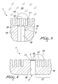
- Fig. 3 illustrates a first embodiment of a controlled nucleate boiling sensor arrangement 1 for measuring a temperature in a cooling circuit.
- a sensor 2 may be inserted into the support structure 18 of a cooling circuit.
- the sensor may be inserted in a hole 16 provided in the support structure 18 of a cooling circuit.
- the hole 16 may be shaped to accommodate sensor 2.
- the hole 16 may be sized so as to accommodate the sensor 2 in a press-fit manner.
- the mounting of the sensor 2 may be achieved by pressing it into the hole 16 with force so that the sensor 2 may be arranged so as to be substantially part of the support structure 18.
- hole 16 may be provided with threading for receiving and mounting sensor 2.
- the hole 16 may have a closed end which may be located in support structure 18.
- a plurality of cavities 12 may be formed in the support structure 18 extending into the surface 11.
- the closed end 33 of the hole 16 may be positioned in the periphery 14.
- the periphery 14 may include a border 35.
- the border 35 may lie between the closed end 33 and the bottom of the cavities 12.
- a suitable metal may constitute the support structure 18. Any suitable form-shaping process, such as laser treatment or stamping or any other suitable forming process may be used to obtain the cavity 12 or the plurality of cavities 12.
- the sensor 2 In operative position the sensor 2 may be inserted in the hole 16 and junction 7 of the sensor 2 may abut the closed end 33.
- the junction 7 may be within the periphery 14.
- Surface 11 may be substantially plane in the region wherein cavities 12 may not be present.
- a liquid coolant 34 may be in contact with the surface 11 and the interior of the cavities 12.
- a bubble 15 may form at the zone of bubble formation 13 and bubble departure may signal that a state of nucleate boiling is reached.
- the sensor 2 abutting the border 35 may accurately monitor the periphery 14 within the zone of bubble formation and thereby detect initiating of the nucleate boiling state.
- the material used for the parts of a cooling system must be suitable to withstand heat and must be corrosion-resistant due to the contact with the liquid coolant. Certain metals, like steel and aluminium fulfil these requirements. Certain polymers or any other material having similar characteristics as the metal described above can be used.
- Fig. 4 illustrates a second embodiment of the controlled nucleate boiling sensor arrangement 1 comprising the sensor 2 in an operative position wherein the sensor 2 may be mounted in the coolant circuit.
- the sensor arrangement 1 may include the sensor 2, which may be mounted in a hole 16 of a support structure 18 of a cooling circuit.
- the hole 16 may be sized so as to accommodate the sensor 2 in a press-fit manner.
- the mounting of the sensor 2 may be achieved by pressing it into the hole 16 with force so that the sensor 2 may be arranged so as to be substantially part of the support structure 18.
- Surface 11 of support structure 18 may be flush with junction 7.
- the support structure 18 may have a plurality of cavities 12 on the surface 11.
- Each of the cavities 12 may be shaped to be substantially cylindrical with an opening at the surface 11.
- each of the opening may have a diameter which may be lesser in magnitude than the depth of the cavities 12
- the plurality of cavities 12 may be spaced apart from the junction 7 so as to form a cluster 17 of cavities 12. Within the cluster 17 the cavities 12 may be arranged randomly or in regular distances from each other at the surface 11 of the support structure 18.
- a bubble 15 may form in the zone of bubble formation 13.
- the junction 7 may be positioned so that at least a part of the bubble 15 may contact the junction 7 of the sensor 2.
- the junction 7 may be adapted to monitor the temperature of the coolant at surface 11 and detect initiation of nucleate boiling, i.e. when one or more bubbles 15 start departing from the cavities 12.
- the junction 7 may also be in contact with the fluid coolant, vapour of a forming bubble or residual vapour of a departed bubble for measuring the actual temperature at that location.
- Fig. 5 illustrates a third embodiment of the controlled nucleate boiling sensor arrangement comprising the sensor 2 according to the disclosure.
- the sensor 2 may be arranged below the cavities 12 of the support structure 18 of the cooling circuit. Cavities 12 may extend through support structure 18 to a hole 16 for receiving sensor 2.
- the junction 7 of the sensor 2 may be arranged so as to be in immediate contact with the bottom of cavities 12 wherein junction 7 may form a bottom surface 19 of the cavities 12.
- the bottom surface 19 may be in direct contact with the zone of bubble formation 13 and with the fluid coolant, vapour of a forming bubble or residual vapour of a departed bubble for measuring the actual temperature at that location.
- the plurality of cavities 12 present in the surface 11 of the support structure 18 may be arranged in regular distances to each other.
- Fig. 6 illustrates a fourth embodiment of the controlled nucleate boiling sensor arrangement.
- the controlled nucleate boiling sensor 2 may be positioned at the zone of bubble formation 13 of a single cavity.
- the junction 7 of the sensor 2 may form the bottom surface 19 of a single cavity.
- Fig. 7 illustrates a second embodiment of the controlled nucleate boiling sensor.
- a sensor 20, which may comprise two-parts. One part may be first section 21, which may be substantially cylindrical and may have an edge 27 at one end. At the other end of first section 21 may be a junction 23 covering a part of the sensor 20, which may be in contact with a liquid coolant during operation of the sensor 20. At the surface 26 of the junction 23 may be a cavities 24 dispersed thereon.
- Fig. 8 illustrates a third embodiment of the controlled nucleate boiling sensor.
- At the surface 26 of the sensor 20 may be a plurality of clusters 28 comprising cavities 24.
- Sensor 20 may fit into a hole 16 of support structure 18. Sensor 20 may detect initiation of a nucleate boiling state at the zone of bubble formation 13 of cavity 24 or at the combined zone of bubble formation. Initiation of a nucleate boiling state may be detected through a portion of sensor 20. The portion of sensor 20 may be junction 23 or a portion of junction 23.
- the cluster 28 may be arranged so as to build a regular pattern having the equal distances to each other or may be arranged in a random configuration.
- a bubble 25 may build up at a cluster 28 so as to cover at least a portion of the cluster 28 or cavity 24 at the surface 26.
- Junction 12 may be adapted to measure a temperature when the bubble 25 begins to depart from the surface 26.
- the junction 23 may be in direct contact with zones of the bubble formation of the cavities 24 or the combined zone of bubble formation of the cavities.
- the junction 23 may also be in contact with the fluid coolant, vapour of a forming bubble or residual vapour of a departed bubble for measuring the actual temperature at that location.
- junction 23 is damaged or cavities 24 are corroded.
- sensor 20 may be exchanged with a new junction 23.
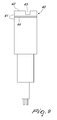
- Fig. 9 illustrates a fourth embodiment of the controlled nucleate boiling sensor.
- Sensor 40 may comprise a first section 41.
- First section 41 may comprise a surface 42.
- Surface 42 may comprise a cavity 43 or a plurality of cavities 43.
- the cavities may be arranged in clusters. Cavities may be formed by machining into first section 41.
- First section 41 may comprise a junction 44 positioned below the cavity 43.
- the junction may be embedded in first section 41 and may be positioned up to 1mm from the surface 42.
- the junction 44 may be in direct contact with zones of the bubble formation of the cavity 43 or the combined zone of bubble formation of a plurality of cavities 43.
- Sensor 40 may detect initiation of a nucleate boiling state at the zone of bubble formation 13 of cavity 43. Initiation of a nucleate boiling state may be detected through a portion of sensor 40.
- the portion of sensor 40 may be junction 44 or a portion of junction 44.
- the layer of first section 41 provided on junction 44 may be removably mounted to the sensor 40.
- the layer of first section 41 may be welded, screwed or pressed on the sensor 40.
- Sensor 40 may be mounted into a hole 16 of support structure 18 by press-fitting or by threading.
- This disclosure describes a controlled nucleate boiling sensor arrangement, wherein the controlled nucleate boiling sensor is arranged in close vicinity to the nucleation cavities and in direct contact with a bubble forming at said cavities.
- the industrial applicability of the controlled nucleate boiling sensor manufactured as part of a cooling system or temperature controlled process or as an add-on element as described herein will be readily appreciated from the foregoing discussion.
- the sensor with the cavities thereon can easily be replaced keeping maintenance low and downtime of the machine to a minimum.
- the present disclosure is applicable to cooling systems for, but not limited to, internal combustion engines.
Landscapes
- Engineering & Computer Science (AREA)
- Chemical & Material Sciences (AREA)
- Combustion & Propulsion (AREA)
- Mechanical Engineering (AREA)
- General Engineering & Computer Science (AREA)
- Cooling Or The Like Of Semiconductors Or Solid State Devices (AREA)
Abstract
Description
- This patent disclosure relates generally to a temperature measurement arrangement of a cooling circuit and a related method in which a sensing device may monitor a surface temperature in a cooling circuit, detect nucleate boiling or control the boiling state of a liquid coolant circulating in the cooling circuit.
- This patent disclosure relates generally to the field of cooling systems for high-temperature generating apparatuses, such as vehicle engines, and to the field of low pressure, low temperature boiling systems, for instance in air conditioning (HVAC) and heating ventilation systems. During operation of the engine, the engine may be kept in operative mode by using a cooling circuit wherein a liquid coolant circulates inside the cooling circuit. A liquid coolant circulating inside the cooling circuit may transport the heat away from a heat source in order to prevent overheating of the engine.
- It is often desirable to prevent or control a nucleate boiling state of the liquid coolant in the cooling circuit, which may enhance the cooling effect significantly. However, an effect known as "film boiling" may occur when bubbles merge and a coolant vapour layer forms at the heated surface. This coolant vapour layer separates the liquid coolant from the heated surface and can act as an insulator. At the point where film boiling initiates, thermal exchange between the surface of the cooling circuit and the coolant inside the circuit may rapidly decrease. The temperature of the heated surface in the region where film boiling occurs may thus escalate to a temperature multiple times higher than the saturation temperature of the coolant. This effect may result in a surface temperature high enough to cause damage to or failure of the heated surface material or structure.
- It is known that thermal exchange may be increased by providing cavities in a surface of the cooling system in contact with the liquid coolant. At a certain wall superheat temperature, bubbles may form and depart from the cavities and transport the heat away from the surface of the cooling system.
- Additionally, in order to control the nucleate boiling state, the cooling system may be influenced to alter the rate of nucleate boiling. This may be done by activation of external ventilation units to reduce coolant temperature, increasing the speed of the coolant flow for transporting the heat away from the heat source, or any other suitable procedures to alter the boiling state .
- In order to control the cooling system, a sensor may be used to measure the temperature of the cooling circuit wall to detect bubble departure. In case a measured temperature exceeds a pre-defined alerting value, measures could be taken to prevent any damage to the cooling system, including derating or stopping the engine until it has cooled down or activating additional cooling systems, e.g. a fan unit, for providing further cooling.
- Although known sensor arrangements may provide temperature indication, they may not measure the temperature accurately, may not provide information quickly enough or measure the temperature at a suitable location to fully control a nucleate boiling state.
- There is a desire to precisely measure the temperature of the cooling circuit heated surface during bubble formation and departure and to identify when nucleate boiling occurs, so as to maintain the circuit in a controlled nucleate boiling state.
- There is also a need for a nucleate boiling sensor arrangement which is adapted to react quickly, preferably in real-time, to keep a liquid coolant in a nucleation boiling state
- This patent disclosure relates generally to a nucleate boiling sensor arrangement for liquid cooling systems, comprising a sensor positioned in a support structure; and at least one nucleation cavity in a support structure, said nucleation cavity having a zone of bubble formation, a portion of the sensor positioned at the zone of bubble formation so as to detect initiation of a nucleate boiling state.
- According to another aspect of the present disclosure, a method of measuring a nucleate boiling temperature of a surface having at least one nucleation cavity in liquid cooling systems, comprising the steps of positioning a portion of a sensor at a zone of bubble formation of at least one cavity and monitoring a temperature at said zone of bubble formation to detect initiation of nucleate boiling state.
- Yet in another aspect of the present disclosure, the disclosure describes a nucleate boiling sensor arrangement adapted to measure a temperature of said liquid coolant in a same plane spanned by said surface.
- The foregoing and other features and advantages of the present disclosure will be more fully understood from the following description of various embodiments, when read together with the accompanying drawings, in which:
-
Fig. 1 is an illustration of a zone of bubble formation of a cavity according to the present disclosure; -
Fig. 2 is a sectional view of a first embodiment of a controlled nucleate boiling sensor of a controlled nucleate boiling sensor arrangement according to the present disclosure; -
Fig. 3 is a sectional view of a first embodiment of a controlled nucleate boiling sensor arrangement according to the present disclosure; -
Fig. 4 is a sectional view of a second embodiment of the controlled nucleate boiling sensor arrangement according to the present disclosure; -
Fig. 5 is a sectional view of a third embodiment of the controlled nucleate boiling sensor arrangement according to the present disclosure; -
Fig. 6 is a sectional view of a fourth embodiment of the controlled nucleate boiling sensor arrangement according to the present disclosure; -
Fig. 7 is an isometric view of a second embodiment of the controlled nucleate boiling sensor of a controlled nucleate boiling sensor arrangement according to the present disclosure; -
Fig. 8 is an isometric view of a third embodiment of the controlled nucleate boiling sensor of a controlled nucleate boiling sensor arrangement according to the present disclosure; and -
Fig. 9 is a side cross section view of a fourth embodiment of the controlled nucleate boiling sensor of a controlled nucleate boiling sensor arrangement according to the present disclosure. - This disclosure generally relates to a controlled nucleate boiling sensor arrangement for liquid cooling systems. Particularly, it relates to a sensor arrangement and process for accurate detection of initiation of a nucleate boiling state and monitoring thereof.
-
Fig. 1 illustrates acavity 12 which may be located in a liquid cooling system for instance in a cooling circuit of a vehicle.Cavity 12 may be formed within asupport structure 18 of the cooling circuit. At a nucleate boiling state bubbles may form incavity 12 and depart therefrom. A bubble may form within a zone ofbubble formation 13 prior to bubble departure. The zone ofbubble formation 13 includes the hollow of thecavity 12 and the proximate region around the aperture ofcavity 12 onsurface 11. In the absence of a bubble said areas may be in contact with a coolant liquid that may circulate through the coolant circuit. During bubble formation and prior to bubble departure said areas may be contact with the vapour of the bubble. Monitoring the temperature at the zone ofbubble formation 13 provides an accurate gauge of bubble formation to thereby accurately detect changes in the boiling state. - In an embodiment the zone of
bubble formation 13 may include theperiphery 14 around thecavity 12 insupport structure 18. Temperature changes within thecavity 12 may be accurately detected within theperiphery 14. - In another embodiment having a plurality of
cavities 12 each cavity may have a zone ofbubble formation 13 such that the plurality of zones may merge to form a single combined zone ofbubble formation 13. -
Fig. 2 illustrates a first embodiment of a controlled nucleate boiling sensor for a controlled nucleate boiling sensor arrangement according to the present disclosure. Asensor 2 may be constituted by three sections. Afirst section 3 having the largest diameter of the sensor may be in contact with the liquid coolant. In direct contact with thefirst section 3 may be asecond section 4, which has a smaller diameter than thefirst section 3. Attached to thesecond section 4 may be athird section 5. Aconnection element 6 may be connected tothird section 5. Theconnection element 6 enables thesensor 2 to be electrically connected to a control system for further processing of the measurements taken by thesensor 2. -
Section 3 may be formed in any suitable shape. In an embodiment,first section 3 may have a generally cylindrical shape.First section 3 may comprise an external layer which may include ajunction 7 and aninsulation shield 10.Insulation shield 10 may be thermally or electrically insulating. At an end,first section 3 may be connected tosecond section 4 and, in an embodiment, at the other end thefirst section 3 may comprise thejunction 7.Junction 7 may be a thin plate and may be in contact with a surface or a substance, for instance a coolant liquid, for monitoring the temperature thereof. Thefirst section 3 may be enclosed on its entire circumference by aninsulation shield 10. Theinsulation shield 10 may protect the sensor from damage when the sensor is installed into the surface of the cooling circuit. Theinsulation shield 10 may also act as a fastening element when mounted into surface of the cooling circuit. Theinsulation shield 10 may be slightly larger in diameter in respect to ahole 16 into whichsensor 2 is to be installed so as to press fit thesensor 2 into thehole 16. The outer surface of theinsulation shield 10 may also have a structure to further provide for a tight fit, such as threads or a knurled structure. - The
first section 3 may be constituted by twodifferent conducting materials first material 9 may occupy the entire volume ofsection 3 except for an annular centre area. The centre area may be constituted by asecond material 8. The first 8 and second 9 material may aid in monitoring a surface or a substance through a portion ofsensor 2 based on a thermoelectric effect between the two materials. -
Sensor 2 may detect initiation of a nucleate boiling state at the zone ofbubble formation 13 or a combined zone of bubble formation. In an embodiment, initiation of a nucleate boiling state may be detected through a portion ofsensor 2. The portion ofsensor 2 may bejunction 7 or a portion ofjunction 7. -
Fig. 3 illustrates a first embodiment of a controlled nucleate boilingsensor arrangement 1 for measuring a temperature in a cooling circuit. In such an arrangement asensor 2 may be inserted into thesupport structure 18 of a cooling circuit. The sensor may be inserted in ahole 16 provided in thesupport structure 18 of a cooling circuit. Thehole 16 may be shaped to accommodatesensor 2. Thehole 16 may be sized so as to accommodate thesensor 2 in a press-fit manner. The mounting of thesensor 2 may be achieved by pressing it into thehole 16 with force so that thesensor 2 may be arranged so as to be substantially part of thesupport structure 18. In an embodiment,hole 16 may be provided with threading for receiving and mountingsensor 2. Thehole 16 may have a closed end which may be located insupport structure 18. A plurality ofcavities 12 may be formed in thesupport structure 18 extending into thesurface 11. Theclosed end 33 of thehole 16 may be positioned in theperiphery 14. Theperiphery 14 may include aborder 35. Theborder 35 may lie between theclosed end 33 and the bottom of thecavities 12. A suitable metal may constitute thesupport structure 18. Any suitable form-shaping process, such as laser treatment or stamping or any other suitable forming process may be used to obtain thecavity 12 or the plurality ofcavities 12. - In operative position the
sensor 2 may be inserted in thehole 16 andjunction 7 of thesensor 2 may abut theclosed end 33. Thejunction 7 may be within theperiphery 14.Surface 11 may be substantially plane in the region whereincavities 12 may not be present. Aliquid coolant 34 may be in contact with thesurface 11 and the interior of thecavities 12. Abubble 15 may form at the zone ofbubble formation 13 and bubble departure may signal that a state of nucleate boiling is reached. Thesensor 2 abutting theborder 35 may accurately monitor theperiphery 14 within the zone of bubble formation and thereby detect initiating of the nucleate boiling state. The material used for the parts of a cooling system must be suitable to withstand heat and must be corrosion-resistant due to the contact with the liquid coolant. Certain metals, like steel and aluminium fulfil these requirements. Certain polymers or any other material having similar characteristics as the metal described above can be used. -
Fig. 4 illustrates a second embodiment of the controlled nucleate boilingsensor arrangement 1 comprising thesensor 2 in an operative position wherein thesensor 2 may be mounted in the coolant circuit. - The
sensor arrangement 1 may include thesensor 2, which may be mounted in ahole 16 of asupport structure 18 of a cooling circuit. Thehole 16 may be sized so as to accommodate thesensor 2 in a press-fit manner. The mounting of thesensor 2 may be achieved by pressing it into thehole 16 with force so that thesensor 2 may be arranged so as to be substantially part of thesupport structure 18.Surface 11 ofsupport structure 18 may be flush withjunction 7. By press-fitting the sensor into thesupport structure 18 of the cooling system no coolant, which circulates at thesurface 11 of thesupport structure 18, may escape from the cooling system through the region of abutment betweenjunction 7 andsurface 11. - The
support structure 18 may have a plurality ofcavities 12 on thesurface 11. Each of thecavities 12 may be shaped to be substantially cylindrical with an opening at thesurface 11. In an embodiment, each of the opening may have a diameter which may be lesser in magnitude than the depth of thecavities 12 - The plurality of
cavities 12 may be spaced apart from thejunction 7 so as to form acluster 17 ofcavities 12. Within thecluster 17 thecavities 12 may be arranged randomly or in regular distances from each other at thesurface 11 of thesupport structure 18. - In a nucleate boiling state of the coolant, a
bubble 15 may form in the zone ofbubble formation 13. Thejunction 7 may be positioned so that at least a part of thebubble 15 may contact thejunction 7 of thesensor 2. Thejunction 7 may be adapted to monitor the temperature of the coolant atsurface 11 and detect initiation of nucleate boiling, i.e. when one ormore bubbles 15 start departing from thecavities 12. Thejunction 7 may also be in contact with the fluid coolant, vapour of a forming bubble or residual vapour of a departed bubble for measuring the actual temperature at that location. -
Fig. 5 illustrates a third embodiment of the controlled nucleate boiling sensor arrangement comprising thesensor 2 according to the disclosure. In this embodiment, thesensor 2 may be arranged below thecavities 12 of thesupport structure 18 of the cooling circuit.Cavities 12 may extend throughsupport structure 18 to ahole 16 for receivingsensor 2. Thejunction 7 of thesensor 2 may be arranged so as to be in immediate contact with the bottom ofcavities 12 whereinjunction 7 may form abottom surface 19 of thecavities 12. Thebottom surface 19 may be in direct contact with the zone ofbubble formation 13 and with the fluid coolant, vapour of a forming bubble or residual vapour of a departed bubble for measuring the actual temperature at that location. The plurality ofcavities 12 present in thesurface 11 of thesupport structure 18 may be arranged in regular distances to each other. -
Fig. 6 illustrates a fourth embodiment of the controlled nucleate boiling sensor arrangement. The controlled nucleate boilingsensor 2 may be positioned at the zone ofbubble formation 13 of a single cavity. In another embodiment, thejunction 7 of thesensor 2 may form thebottom surface 19 of a single cavity. -
Fig. 7 illustrates a second embodiment of the controlled nucleate boiling sensor. Asensor 20, which may comprise two-parts. One part may befirst section 21, which may be substantially cylindrical and may have anedge 27 at one end. At the other end offirst section 21 may be ajunction 23 covering a part of thesensor 20, which may be in contact with a liquid coolant during operation of thesensor 20. At thesurface 26 of thejunction 23 may be acavities 24 dispersed thereon. -
Fig. 8 illustrates a third embodiment of the controlled nucleate boiling sensor. At thesurface 26 of thesensor 20 may be a plurality ofclusters 28 comprisingcavities 24. -
Sensor 20 may fit into ahole 16 ofsupport structure 18.Sensor 20 may detect initiation of a nucleate boiling state at the zone ofbubble formation 13 ofcavity 24 or at the combined zone of bubble formation. Initiation of a nucleate boiling state may be detected through a portion ofsensor 20. The portion ofsensor 20 may bejunction 23 or a portion ofjunction 23. - The
cluster 28 may be arranged so as to build a regular pattern having the equal distances to each other or may be arranged in a random configuration. During initiation of nucleate boiling abubble 25 may build up at acluster 28 so as to cover at least a portion of thecluster 28 orcavity 24 at thesurface 26.Junction 12 may be adapted to measure a temperature when thebubble 25 begins to depart from thesurface 26. Thejunction 23 may be in direct contact with zones of the bubble formation of thecavities 24 or the combined zone of bubble formation of the cavities. Thejunction 23 may also be in contact with the fluid coolant, vapour of a forming bubble or residual vapour of a departed bubble for measuring the actual temperature at that location. - An accurate temperature measurement may not be possible if
junction 23 is damaged orcavities 24 are corroded. In such anevent sensor 20 may be exchanged with anew junction 23. -
Fig. 9 illustrates a fourth embodiment of the controlled nucleate boiling sensor.Sensor 40 may comprise afirst section 41.First section 41 may comprise asurface 42.Surface 42 may comprise acavity 43 or a plurality ofcavities 43. The cavities may be arranged in clusters. Cavities may be formed by machining intofirst section 41. -
First section 41 may comprise ajunction 44 positioned below thecavity 43. The junction may be embedded infirst section 41 and may be positioned up to 1mm from thesurface 42. Thejunction 44 may be in direct contact with zones of the bubble formation of thecavity 43 or the combined zone of bubble formation of a plurality ofcavities 43. -
Sensor 40 may detect initiation of a nucleate boiling state at the zone ofbubble formation 13 ofcavity 43. Initiation of a nucleate boiling state may be detected through a portion ofsensor 40. The portion ofsensor 40 may bejunction 44 or a portion ofjunction 44. - In an embodiment, the layer of
first section 41 provided onjunction 44 may be removably mounted to thesensor 40. The layer offirst section 41 may be welded, screwed or pressed on thesensor 40. -
Sensor 40 may be mounted into ahole 16 ofsupport structure 18 by press-fitting or by threading. - Existing coolant systems may be easily upgraded with a nucleate boiling sensor arrangement according to the present disclosure.
- This disclosure describes a controlled nucleate boiling sensor arrangement, wherein the controlled nucleate boiling sensor is arranged in close vicinity to the nucleation cavities and in direct contact with a bubble forming at said cavities.
- The industrial applicability of the controlled nucleate boiling sensor manufactured as part of a cooling system or temperature controlled process or as an add-on element as described herein will be readily appreciated from the foregoing discussion. In case a sensor breaks or the cavities corrode, the sensor with the cavities thereon can easily be replaced keeping maintenance low and downtime of the machine to a minimum. The present disclosure is applicable to cooling systems for, but not limited to, internal combustion engines.
- Accordingly, this invention includes all modifications and equivalents of the subject matter recited in the claims appended hereto as permitted by applicable law. Moreover, any combination of the above-described elements in all possible variations thereof is encompassed by the invention unless otherwise indicated herein.
- Where reference signs follow technical features mentioned in any claim, the reference signs have been included for the sole purpose of increasing the intelligibility of the claims. Neither the reference signs nor their absence have any limiting effect on the technical features as described above or on the scope of any claim elements.
- One skilled in the art will realize the invention may be embodied in other specific forms without departing from the invention or essential characteristics thereof. The foregoing embodiments are therefore to be considered in all respects illustrative rather than limiting of the invention described herein. The scope of the invention is thus indicated by the appended claims, rather than by the foregoing description. Moreover, all changes that come within the meaning and range of equivalence of the claims are therefore intended to be embraced therein.
Claims (14)
- A controlled nucleate boiling sensor arrangement (1) for liquid cooling systems, comprising:a sensor (2, 20, 40) positioned in a support structure (18); andat least one nucleation cavity (12, 24, 43) having a zone of bubble formation (13); wherein at least a portion of the sensor (2, 20) is positioned at the zone of bubble formation (13).
- The controlled nucleate boiling sensor arrangement according to claim 1, wherein said portion of said sensor (2, 20, 40) is flush with a surface (11) of support structure (18).
- The controlled nucleate boiling sensor arrangement according to claim 2, wherein said support structure (18) includes a hole (16) for accommodating the sensor (2, 20, 40).
- The controlled nucleate boiling sensor arrangement according to claims 2 or 3, wherein the nucleation cavity (12) is spaced apart from the portion of sensor (2) and positioned on said support structure (18).
- The controlled nucleate boiling sensor arrangement according to claims 1, 2 or 3, wherein the nucleation cavity is formed on the portion of sensor ( 20, 40).
- The controlled nucleate boiling sensor arrangement according to claim 5, wherein said the portion of sensor (20) is removably mounted on a first section (21).
- The controlled nucleate boiling sensor arrangement according to claim 1, wherein said the portion of sensor (2, 20, 40) is positioned at the base of the nucleation cavity (12, 24, 43).
- The controlled nucleate boiling sensor arrangement according to any one of the preceding claims comprising a plurality of nucleation cavities.
- The controlled nucleate boiling sensor arrangement according to claim 8, wherein the plurality of cavities (24) are grouped in clusters (28).
- The controlled nucleate boiling sensor arrangement according to any one of the preceding claims wherein the portion of said sensor is junction (7, 23, 44).
- A method of measuring a nucleate boiling temperature of a surface (11, 26, 42) having at least one nucleation cavity in liquid cooling systems, comprising the steps of:- positioning at least portion of a sensor (2, 20, 49) at a zone of bubble formation (13) of at least one cavity (12, 24, 43); and- monitoring a temperature at said zone of bubble formation (13).
- The method of measuring a nucleate boiling temperature of a surface (11, 26, 42) in liquid cooling systems according to claim 11, wherein said portion of sensor is arranged so as to substantially form part of a support structure (18).
- The method of claim 11 wherein the nucleation cavity (12) is spaced apart from the portion of sensor (2).
- The method of claim 11 wherein the nucleation cavity (12) is integral with the portion of sensor (2).
Priority Applications (1)
| Application Number | Priority Date | Filing Date | Title |
|---|---|---|---|
| EP08166816A EP2177733A1 (en) | 2008-10-16 | 2008-10-16 | Controlled nucleate boiling sensor |
Applications Claiming Priority (1)
| Application Number | Priority Date | Filing Date | Title |
|---|---|---|---|
| EP08166816A EP2177733A1 (en) | 2008-10-16 | 2008-10-16 | Controlled nucleate boiling sensor |
Publications (1)
| Publication Number | Publication Date |
|---|---|
| EP2177733A1 true EP2177733A1 (en) | 2010-04-21 |
Family
ID=40524837
Family Applications (1)
| Application Number | Title | Priority Date | Filing Date |
|---|---|---|---|
| EP08166816A Withdrawn EP2177733A1 (en) | 2008-10-16 | 2008-10-16 | Controlled nucleate boiling sensor |
Country Status (1)
| Country | Link |
|---|---|
| EP (1) | EP2177733A1 (en) |
Citations (4)
| Publication number | Priority date | Publication date | Assignee | Title |
|---|---|---|---|---|
| JPH02115755A (en) * | 1988-10-26 | 1990-04-27 | Toshiba Corp | Abnormality detector for cooling water circulating system of rotating electric machinery |
| DE4113294C1 (en) * | 1991-04-24 | 1992-06-17 | Fa. Carl Freudenberg, 6940 Weinheim, De | |
| US20020049015A1 (en) * | 1997-06-16 | 2002-04-25 | Akitaka Suzuki | Exhaust and control for watercraft engine |
| WO2003038251A1 (en) * | 2001-10-22 | 2003-05-08 | Robert Bosch Gmbh | Method, computer program and control and/or regulation device, for operating an internal combustion engine, as well as an internal combustion engine |
-
2008
- 2008-10-16 EP EP08166816A patent/EP2177733A1/en not_active Withdrawn
Patent Citations (4)
| Publication number | Priority date | Publication date | Assignee | Title |
|---|---|---|---|---|
| JPH02115755A (en) * | 1988-10-26 | 1990-04-27 | Toshiba Corp | Abnormality detector for cooling water circulating system of rotating electric machinery |
| DE4113294C1 (en) * | 1991-04-24 | 1992-06-17 | Fa. Carl Freudenberg, 6940 Weinheim, De | |
| US20020049015A1 (en) * | 1997-06-16 | 2002-04-25 | Akitaka Suzuki | Exhaust and control for watercraft engine |
| WO2003038251A1 (en) * | 2001-10-22 | 2003-05-08 | Robert Bosch Gmbh | Method, computer program and control and/or regulation device, for operating an internal combustion engine, as well as an internal combustion engine |
Similar Documents
| Publication | Publication Date | Title |
|---|---|---|
| US11125830B2 (en) | Motor driving device and detection method for detecting malfunction in heat radiation performance of heatsink | |
| CA2648816A1 (en) | A transformer and a method of monitoring an operation property of the transformer | |
| US20190154517A1 (en) | Heat flux meter and abnormality diagnosis device | |
| JP6602717B2 (en) | Maintenance method of refrigeration unit | |
| US20160103020A1 (en) | Measuring device, in particular for use in the process measurement technology, comprising a cylindrical sensor tip | |
| US7473868B2 (en) | Fail safe HVAC temperature and medium presence sensor | |
| EP2493275A2 (en) | Dew-condensation detecting apparatus, electronic equipment cooling system, and dew-condensation detecting method | |
| JP6830333B2 (en) | Unit system with temperature control function | |
| EP2177733A1 (en) | Controlled nucleate boiling sensor | |
| JP5732826B2 (en) | Casting inspection method | |
| EP3220108B1 (en) | Liquid level sensor, method for controlling the same and reactor with the same | |
| US20130133854A1 (en) | Heat exchange apparatus | |
| CN113251705A (en) | Temperature sensor mounting on microchannel heat exchanger | |
| JPH04225126A (en) | Resin-temperature measuring apparatus | |
| JP2765157B2 (en) | Bearing abnormality monitoring device | |
| JP6027955B2 (en) | Hygrometer component, hygrometer, and environmental test device | |
| KR20140055169A (en) | Cold water tank | |
| CN223756180U (en) | Dry type temperature calibrator | |
| JP2003149053A (en) | Method and apparatus for measurement of temperature change of pipe, etc | |
| JPWO2018092828A1 (en) | Thermometer and joint for thermometer | |
| JP2004209509A (en) | Thermometer for metallic mold cooling water and metallic mold cooling system | |
| SU513555A1 (en) | Apparatus for monitoring slag and metal level in electroslag melting | |
| CN106441959A (en) | IGBT module heat radiation performance assessment method | |
| JP2010008211A (en) | Temperature-monitoring device | |
| KR101606747B1 (en) | device for surface heat flux measurement and manufacturing method thereof |
Legal Events
| Date | Code | Title | Description |
|---|---|---|---|
| PUAI | Public reference made under article 153(3) epc to a published international application that has entered the european phase |
Free format text: ORIGINAL CODE: 0009012 |
|
| AK | Designated contracting states |
Kind code of ref document: A1 Designated state(s): AT BE BG CH CY CZ DE DK EE ES FI FR GB GR HR HU IE IS IT LI LT LU LV MC MT NL NO PL PT RO SE SI SK TR |
|
| AX | Request for extension of the european patent |
Extension state: AL BA MK RS |
|
| 17P | Request for examination filed |
Effective date: 20101020 |
|
| 17Q | First examination report despatched |
Effective date: 20101118 |
|
| AKX | Designation fees paid |
Designated state(s): AT BE BG CH CY CZ DE DK EE ES FI FR GB GR HR HU IE IS IT LI LT LU LV MC MT NL NO PL PT RO SE SI SK TR |
|
| STAA | Information on the status of an ep patent application or granted ep patent |
Free format text: STATUS: THE APPLICATION IS DEEMED TO BE WITHDRAWN |
|
| 18D | Application deemed to be withdrawn |
Effective date: 20140501 |