EP2177705A2 - Schattenspendende Anordnung mit versteckter Befestigungsvorrichtung - Google Patents
Schattenspendende Anordnung mit versteckter Befestigungsvorrichtung Download PDFInfo
- Publication number
- EP2177705A2 EP2177705A2 EP09252384A EP09252384A EP2177705A2 EP 2177705 A2 EP2177705 A2 EP 2177705A2 EP 09252384 A EP09252384 A EP 09252384A EP 09252384 A EP09252384 A EP 09252384A EP 2177705 A2 EP2177705 A2 EP 2177705A2
- Authority
- EP
- European Patent Office
- Prior art keywords
- solar
- bracket
- louver member
- shading assembly
- fastening device
- Prior art date
- Legal status (The legal status is an assumption and is not a legal conclusion. Google has not performed a legal analysis and makes no representation as to the accuracy of the status listed.)
- Withdrawn
Links
- 239000002184 metal Substances 0.000 description 3
- 230000000712 assembly Effects 0.000 description 2
- 238000000429 assembly Methods 0.000 description 2
- 229920003023 plastic Polymers 0.000 description 2
- 239000004033 plastic Substances 0.000 description 2
- 238000001125 extrusion Methods 0.000 description 1
- 238000004519 manufacturing process Methods 0.000 description 1
- 238000012986 modification Methods 0.000 description 1
- 230000004048 modification Effects 0.000 description 1
Images


Classifications
-
- E—FIXED CONSTRUCTIONS
- E04—BUILDING
- E04F—FINISHING WORK ON BUILDINGS, e.g. STAIRS, FLOORS
- E04F10/00—Sunshades, e.g. Florentine blinds or jalousies; Outside screens; Awnings or baldachins
- E04F10/08—Sunshades, e.g. Florentine blinds or jalousies; Outside screens; Awnings or baldachins of a plurality of similar rigid parts, e.g. slabs, lamellae
-
- E—FIXED CONSTRUCTIONS
- E06—DOORS, WINDOWS, SHUTTERS, OR ROLLER BLINDS IN GENERAL; LADDERS
- E06B—FIXED OR MOVABLE CLOSURES FOR OPENINGS IN BUILDINGS, VEHICLES, FENCES OR LIKE ENCLOSURES IN GENERAL, e.g. DOORS, WINDOWS, BLINDS, GATES
- E06B7/00—Special arrangements or measures in connection with doors or windows
- E06B7/02—Special arrangements or measures in connection with doors or windows for providing ventilation, e.g. through double windows; Arrangement of ventilation roses
-
- E—FIXED CONSTRUCTIONS
- E06—DOORS, WINDOWS, SHUTTERS, OR ROLLER BLINDS IN GENERAL; LADDERS
- E06B—FIXED OR MOVABLE CLOSURES FOR OPENINGS IN BUILDINGS, VEHICLES, FENCES OR LIKE ENCLOSURES IN GENERAL, e.g. DOORS, WINDOWS, BLINDS, GATES
- E06B7/00—Special arrangements or measures in connection with doors or windows
- E06B7/02—Special arrangements or measures in connection with doors or windows for providing ventilation, e.g. through double windows; Arrangement of ventilation roses
- E06B7/08—Louvre doors, windows or grilles
- E06B7/082—Louvre doors, windows or grilles with rigid or slidable lamellae
-
- E—FIXED CONSTRUCTIONS
- E06—DOORS, WINDOWS, SHUTTERS, OR ROLLER BLINDS IN GENERAL; LADDERS
- E06B—FIXED OR MOVABLE CLOSURES FOR OPENINGS IN BUILDINGS, VEHICLES, FENCES OR LIKE ENCLOSURES IN GENERAL, e.g. DOORS, WINDOWS, BLINDS, GATES
- E06B9/00—Screening or protective devices for wall or similar openings, with or without operating or securing mechanisms; Closures of similar construction
- E06B9/24—Screens or other constructions affording protection against light, especially against sunshine; Similar screens for privacy or appearance; Slat blinds
- E06B9/26—Lamellar or like blinds, e.g. venetian blinds
- E06B9/38—Other details
- E06B9/386—Details of lamellae
-
- F—MECHANICAL ENGINEERING; LIGHTING; HEATING; WEAPONS; BLASTING
- F24—HEATING; RANGES; VENTILATING
- F24F—AIR-CONDITIONING; AIR-HUMIDIFICATION; VENTILATION; USE OF AIR CURRENTS FOR SCREENING
- F24F13/00—Details common to, or for air-conditioning, air-humidification, ventilation or use of air currents for screening
- F24F13/08—Air-flow control members, e.g. louvres, grilles, flaps or guide plates
Definitions
- the present invention relates to a solar-shading assembly for fastening to a support mullion, the assembly having a hidden fastening device.
- Solar-shading is known, and is frequently used on the exterior of a building to prevent or limit directly incident solar energy on windows. Louvers are known which are supported at their lateral ends, and which can also be supported along their edge lengths.
- brackets and fastenings are fully visible. From an aesthetic point of view, architects prefer to have as few of the fixings and fasteners on view as possible.
- the rotational load is such that bracket locations must necessarily be very close to prevent catastrophic mechanical failure.
- the present invention seeks to provide a solution to these problems.
- a solar-shading assembly for fastening to a support mullion, the assembly comprising an elongate louver member having longitudinal front and rear edges, an elongate cap element for extending along and covering the rear edge, a bracket which is connectable to the support mullion, and a fastening device for connecting the bracket to the rear edge of the louver member, the in use fastening device being coverable by the cap element so as to hide the fastening device from view.
- a support mullion in combination with a solar-shading assembly according to the first aspect of the invention, wherein the bracket holds the louver member and cap element in close proximity whereby a lateral end edge of the cap element is abuttable with the support mullion.
- a support mullion in combination with a solar-shading assembly in accordance with the first aspect of the invention, wherein the bracket holds the louver member and cap element spaced from the support mullion.
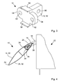
- FIG. 1 to 3 of the drawings there is shown a first embodiment of a solar-shading assembly 10 and a support mullion 12, typically fixed to project externally of a building.
- the solar-shading assembly 10 includes an elongate louver member 14, an elongate cap element 16, a bracket 18 for attachment to the support mullion 12, and a fastening device 20 for fastening the bracket 18 to the louver member 14.
- the louver member 14 in this case, is one-piece and may be, for example, an extrusion from plastics or metal.
- the louver member 14 may be two-pieces, for example, an upper part and a lower part, connected together via snap-fitting and/or one or more screw-threaded fasteners.
- the louver member 14 has an elongate body 22 with longitudinal parallel front and rear edges 24, 26, lateral end sides 28 which, if free, are typically capped, and upper and lower surfaces 30, 32 which span between the front and rear edges 24, 26 and end sides 28.
- a longitudinal extent of the louver member 14 is straight or rectilinear, but it may be curved in some cases.
- the upper surface 30 and a lower surface 32 of the louver member 14 have arcuate lateral extents which converge to a narrow edge to form the longitudinal front edge 24.
- the upper and lower surfaces 30, 32 taper towards each other, but remain spaced thereby providing a deep blunt longitudinal rear edge 26.
- the rear edge 26 includes a channel 34 which is parallel with the front edge 24, and which runs the entire longitudinal extent of the louver member 14.
- the channel 34 includes a bottom surface 36 and two opposing side walls 38 which are adjacent to edges 40 of the upper and lower surfaces 30, 32 of the louver member 14.
- An opening 42 of the channel 34 faces away from the front edge 24.
- Leading edges of the side walls 38 have in-turned leading edge portions 44 which extend along the longitudinal extent of the louver member 14, whereby the channel 34 has a C-shaped or substantially C-shaped lateral cross-section.
- Leading edges of the side walls 38 also have out-turned leading edge portions 46 which extend along the longitudinal extent of the louver member 14, and in parallel with the in-turned leading edge portions 44.
- the cap element 16 has a V-shaped or substantially V-shaped lateral cross-section, and may be plastics or metal. Free leading edges 48 of the cap element 16 include in-turned edge portions 50 for snap-fit connection with the out-turned leading edge portions 46 of the louver member 14. With the cap element 16 connected to the rear edge 26 of the louver member 14, a louver having a symmetrical elliptical or substantially elliptical lateral cross-section is defined. A lateral cross-sectional shape of the cap element 16 matches or substantially matches a lateral shape of a front portion of the louver member 14 which includes the front edge 24.
- the bracket 18 is best seen in Figure 3 , and comprises a mullion connector 52 and two arms, tabs or wings 54 which extend laterally in opposite directions from an end of the mullion connector 52.
- the bracket 18 is beneficially one-piece, preferably being cast or moulded metal, and also includes spaced forwardly-projecting upper and lower lips 56, 58 which extend from the mullion connector 52, between the wings 54.
- the mullion connector 52 includes at least one aperture 60 at one end opposite the end with the wings 54 for connection with the support mullion 12.
- the wings 54 also each include at least one aperture 62 to enable connection with the fastening device 20.
- the fastening device 20 includes an anchor element 64 (shown in Figure 5 ) which is slidable in the channel 34 of the louver member 14.
- the anchor element 64 spans and overlaps the opening 42 of the channel 34 so as to engage the in-turned leading edge portions 44.
- the anchor element 64 includes two spaced apertures therethrough for receiving two separate screw-threaded fasteners 68.
- the heads of the fasteners 68 may be recessed into the anchor element 64.
- the recesses may be complimentarily shaped to match non-circular heads of the fasteners 68 and thereby prevent rotation.
- the threaded shafts 70 project from the anchor element 64 and also from the channel 34.
- the anchor element 64 is slidably received in the channel 34 in the rear edge 26 of the louver member 14, typically by being inserted from one end of the channel 34 and slid therealong.
- the bracket 18 is loosely connected using nuts to the screw-threaded shafts 70 of the fasteners 68 projecting from the anchor element 64 and the channel 34.
- the louver member 14 is offered up to the support mullion 12, typically into a channel 72 of the support mullion 12, and the mullion connector 52 is connected thereto, for example, by a fastener which passes through the support mullion 12 and the mullion connector 52 therein.
- the wings 54 of the fastening device 20 are tightened to the anchor element 64 in the channel 34 of the rear edge 26, which effectively draws the louver member 14 into contact with or closely adjacent to the support mullion 12.
- the forwardly projecting lips 56, 58 of the bracket 18 overlap the rear edge 26 to abut edges 40 of the upper and lower surfaces 30, 32 of the louver member 14.
- the cap element 16 is preferably cut to length by the installer so as to fit closely between two adjacent support mullions 12.
- Each cap element 16 is then snap-fitted to the rear edge 26 of the louver member 14, so that the entire longitudinal extent of the rear edge 26 is covered and hidden by the cap elements 16, except for gaps which allow the mullion connectors 52 to project. Due to the lateral end sides 76 of the cap element 16 abutting or substantially abutting the support mullions 12, the wings 54 of the brackets 18, and thus also the fastening devices 20, are fully covered and hidden from view by the cap elements 16.
- a second embodiment of the solar-shading assembly 10 is shown. Like references refer to like parts, and further detailed description is omitted.
- a longitudinal extent of the mullion connector 52 of the bracket 18 is greater, allowing the louver member 14 and cap element 16 to be spaced from the support mullion 12.
- Each lateral end side 76 of the cap element 16 therefore abuts or substantially abuts the respective mullion connector 52 of the bracket 18, instead of the support mullion 12.
- the cap element 16 covers the wings 54 of the brackets 18 at each end, and thus also the fastening devices 20. The fastening devices 20 are thus again fully covered and hidden from view.
- the mullion connectors of the brackets may be straight or rectilinear, as in the first embodiment, or curved or arcuate as in the second embodiment. In either case, the mullion connector may be short enough to hold the louver member against or substantially against a front edge of the associated support mullion, whereby the lateral end side of the cap element abuts the side of the support mullion, or may be long enough to space the louver member and cap element away from the support mullion, so that the lateral end side of the cap element abuts the side of the mullion connector.
- anchor element having two threaded fasteners extending therefrom
- the anchor element could simply be the head of a fastener or bolt, providing the channel opening defined by the in-turned leading edge portions of the sides of the channel is narrow enough.
- the anchor element may be integrally formed as one-piece with one or more screw-threaded shafts.
- the anchor element may also be a block having one or more screw-threaded openings to receive a threaded shaft of a bolt or other fastener.
- the anchor element may also include a coil spring on its back side to bias the anchor body against the in-turned leading edge portions of the sides of the channel.
- each wing extends at right angles to the mullion connector. However, other angles can be envisaged, for example, if the louver member and the cap element are to extend around a corner.
- the cap element is a snap fit, but may be fastened by additional or alternative means, such as bonding or screw-threaded fasteners.
- the cap element is preferably V-shaped, to match a front edge portion of the louver member, but may be other shapes providing the fastening device can be hidden from view.
- the louver member is preferably one-piece, but may comprise a main middle section with a secondary cap element being provided to form a tapering front edge.
- the rear edge cap element and the front edge cap element may be substantially the same as each other. This would enable louvers of greater lateral dimensions to be produced and installed.
- louver is elliptical, other shapes are feasible.
- a plurality of cap elements is used to cover the rear edge of the louver member.
- the bracket and fastening device are resilient and compact, and therefore cost-effective to produce.
- the fastening device is held internally within the louver, which comprises the louver member and the cap element, and can thus be hidden from view.
- the bracket extends from between two adjacent cap elements, whereby the rear edge of the louver member is covered and hidden from view.
- the louver member is also one-piece or two-pieces, thereby reducing parts, increasing lightness, and increasing cost-effectiveness.
Landscapes
- Engineering & Computer Science (AREA)
- Structural Engineering (AREA)
- Architecture (AREA)
- Civil Engineering (AREA)
- Chemical & Material Sciences (AREA)
- Combustion & Propulsion (AREA)
- Mechanical Engineering (AREA)
- General Engineering & Computer Science (AREA)
- Load-Bearing And Curtain Walls (AREA)
- Roof Covering Using Slabs Or Stiff Sheets (AREA)
- Blinds (AREA)
Applications Claiming Priority (1)
| Application Number | Priority Date | Filing Date | Title |
|---|---|---|---|
| GB0818750.2A GB2464454B (en) | 2008-10-14 | 2008-10-14 | Solar-shading assembly with hidden fastening device |
Publications (2)
| Publication Number | Publication Date |
|---|---|
| EP2177705A2 true EP2177705A2 (de) | 2010-04-21 |
| EP2177705A3 EP2177705A3 (de) | 2011-02-23 |
Family
ID=40083951
Family Applications (1)
| Application Number | Title | Priority Date | Filing Date |
|---|---|---|---|
| EP09252384A Withdrawn EP2177705A3 (de) | 2008-10-14 | 2009-10-08 | Schattenspendende Anordnung mit versteckter Befestigungsvorrichtung |
Country Status (3)
| Country | Link |
|---|---|
| US (1) | US8256167B2 (de) |
| EP (1) | EP2177705A3 (de) |
| GB (2) | GB2464454B (de) |
Cited By (1)
| Publication number | Priority date | Publication date | Assignee | Title |
|---|---|---|---|---|
| WO2012032396A2 (en) | 2010-09-07 | 2012-03-15 | Renson Sunprotection Projects Nv | Slat profile for holding an led strip and slat wall comprising such a slat profile |
Families Citing this family (3)
| Publication number | Priority date | Publication date | Assignee | Title |
|---|---|---|---|---|
| US8331028B2 (en) * | 2011-04-21 | 2012-12-11 | Alcoa Inc. | Light shelf for buildings |
| US9416590B2 (en) | 2014-11-04 | 2016-08-16 | Extech/Exterior Technologies, Inc. | Building envelope solar heat and daylighting control system |
| AU2020339851A1 (en) * | 2019-08-27 | 2022-03-31 | Valmont Australia Pty Ltd | Screening element, screen assembly and mounting system |
Citations (3)
| Publication number | Priority date | Publication date | Assignee | Title |
|---|---|---|---|---|
| WO1990005602A1 (en) * | 1988-11-17 | 1990-05-31 | Hydro Aluminium Tønder A/S | A method of joining stiff plate profile members into broad lamellae or panels and a lamella or panel element or product produced by that method |
| US5548925A (en) * | 1995-06-14 | 1996-08-27 | Marocco; Norbert | Toggle connector for shutter control bar |
| GB2370598A (en) | 2000-12-23 | 2002-07-03 | Levolux At Ltd | Louvre assemblies for mounting on buildings |
Family Cites Families (14)
| Publication number | Priority date | Publication date | Assignee | Title |
|---|---|---|---|---|
| US1340252A (en) * | 1919-09-05 | 1920-05-18 | Niels C Rasmussen | Blind-slat attachment |
| US3004306A (en) * | 1959-08-11 | 1961-10-17 | Edward C Hallock | Bracket assembly for airfoil type louver blade |
| US3438167A (en) * | 1967-03-09 | 1969-04-15 | Airotec Inc | Solar shade apparatus with splicing means |
| DK158104C (da) * | 1981-09-28 | 1990-08-20 | Alusol Dasolas Ab | Skaermkonstruktion med gennemgaaende skaermlameller, der med en fodflange er fastholdt i indbyrdes adskilte baerekonsoller |
| GB2135044B (en) * | 1983-02-08 | 1986-06-11 | John Sidney Jordan | Louvre and mullion system |
| US5187896A (en) * | 1992-03-30 | 1993-02-23 | Dominion Plastics Inc. | Pivot rod connector for moveable shutters |
| NZ328726A (en) * | 1997-09-12 | 2000-09-29 | Interlock Group Ltd | Removable blade mountings for louvre windows |
| US6250012B1 (en) * | 1997-11-28 | 2001-06-26 | Ricci Tools Inc. | Louver assembly with multi-position louver adjusting control rod having clamping connecting arms |
| GB2374376B (en) * | 2001-04-11 | 2004-04-28 | Levolux At Ltd | A louvre system |
| CA2350537C (en) * | 2001-06-14 | 2006-03-14 | Hunter Douglas Canada, Inc. | Louver control bar with bendable louver attachment members |
| US6901988B2 (en) * | 2001-07-16 | 2005-06-07 | Hunter Douglas Inc. | Shutter-like covering and hardware for architectural opening |
| DE102006005238A1 (de) * | 2006-02-06 | 2007-08-16 | Hydro Building Systems Gmbh | Lamellenanordnung für Gebäudefassaden und dergleichen |
| US7544893B2 (en) * | 2007-07-25 | 2009-06-09 | Thomas & Betts International, Inc. | Extruded wire duct end cap |
| US7607261B2 (en) * | 2007-11-14 | 2009-10-27 | Mario M Marocco | Toggle bar and shutter |
-
2008
- 2008-10-14 GB GB0818750.2A patent/GB2464454B/en active Active
- 2008-10-14 GB GB1311359.2A patent/GB2500838B/en active Active
-
2009
- 2009-10-01 US US12/571,784 patent/US8256167B2/en active Active
- 2009-10-08 EP EP09252384A patent/EP2177705A3/de not_active Withdrawn
Patent Citations (3)
| Publication number | Priority date | Publication date | Assignee | Title |
|---|---|---|---|---|
| WO1990005602A1 (en) * | 1988-11-17 | 1990-05-31 | Hydro Aluminium Tønder A/S | A method of joining stiff plate profile members into broad lamellae or panels and a lamella or panel element or product produced by that method |
| US5548925A (en) * | 1995-06-14 | 1996-08-27 | Marocco; Norbert | Toggle connector for shutter control bar |
| GB2370598A (en) | 2000-12-23 | 2002-07-03 | Levolux At Ltd | Louvre assemblies for mounting on buildings |
Cited By (4)
| Publication number | Priority date | Publication date | Assignee | Title |
|---|---|---|---|---|
| WO2012032396A2 (en) | 2010-09-07 | 2012-03-15 | Renson Sunprotection Projects Nv | Slat profile for holding an led strip and slat wall comprising such a slat profile |
| BE1019475A5 (nl) * | 2010-09-07 | 2012-07-03 | Renson Sunprot Projects Nv | Lamellenprofiel voor het houden van ledstrip en lamellenwand omvattende een dergelijk lamellenprofiel. |
| WO2012032396A3 (en) * | 2010-09-07 | 2012-10-18 | Renson Sunprotection Projects Nv | Slat profile for holding an led strip and slat wall comprising such a slat profile |
| US8858014B2 (en) | 2010-09-07 | 2014-10-14 | Renson Sunprotection Projects Nv | Slat profile for holding an LED strip and slat wall comprising such a slat profile |
Also Published As
| Publication number | Publication date |
|---|---|
| GB2464454B (en) | 2013-08-07 |
| GB201311359D0 (en) | 2013-08-14 |
| GB2500838A (en) | 2013-10-02 |
| US20100088960A1 (en) | 2010-04-15 |
| EP2177705A3 (de) | 2011-02-23 |
| GB2500838B (en) | 2013-12-25 |
| US8256167B2 (en) | 2012-09-04 |
| GB2464454A (en) | 2010-04-21 |
| GB0818750D0 (en) | 2008-11-19 |
Similar Documents
| Publication | Publication Date | Title |
|---|---|---|
| US6827471B1 (en) | Recessed light fixture | |
| US8833015B2 (en) | System for mounting wall panels to a wall structure | |
| US8256167B2 (en) | Solar-shading assembly with hidden fastening device | |
| CA2514829A1 (en) | Construction unit mounting system | |
| US20080203247A1 (en) | Clip | |
| CA2985004A1 (en) | Rain gutter cover and rain gutter including same | |
| AU2011340799A1 (en) | Frame connection | |
| EP2948704B1 (de) | Drahtmanagementsystem | |
| US20160053791A1 (en) | Attachment element | |
| CN104519770A (zh) | 抽屉 | |
| EP2292856A3 (de) | Verbinder | |
| SE535583C2 (sv) | Kantlist för montering av väggskiva | |
| KR20190138281A (ko) | 차량의 내부 구성요소 | |
| CN210738352U (zh) | 新型装配式窗系统 | |
| CA2896926A1 (en) | Improved wall panel trim system and method | |
| WO2011127518A1 (en) | Improved screening device and system | |
| GB2454006A (en) | A support structure | |
| US20140090326A1 (en) | Aesthetic wall facade systems, devices, and methods | |
| US9187893B2 (en) | Method and apparatus for under mounted skirt for a mobile home | |
| EP2942451A1 (de) | Befestigungssystem für profilabschnitt | |
| US9862354B2 (en) | Wiper blade device | |
| US20240060310A1 (en) | A multipart bracket and rainscreen cladding mount system including same | |
| WO2012009743A1 (en) | A clamp assembly for an improved screening device | |
| EP4459065B1 (de) | Gebäudelamellenanordnung | |
| CA3186046A1 (en) | Lamella wall system |
Legal Events
| Date | Code | Title | Description |
|---|---|---|---|
| PUAI | Public reference made under article 153(3) epc to a published international application that has entered the european phase |
Free format text: ORIGINAL CODE: 0009012 |
|
| AK | Designated contracting states |
Kind code of ref document: A2 Designated state(s): AT BE BG CH CY CZ DE DK EE ES FI FR GB GR HR HU IE IS IT LI LT LU LV MC MK MT NL NO PL PT RO SE SI SK SM TR |
|
| AX | Request for extension of the european patent |
Extension state: AL BA RS |
|
| PUAL | Search report despatched |
Free format text: ORIGINAL CODE: 0009013 |
|
| AK | Designated contracting states |
Kind code of ref document: A3 Designated state(s): AT BE BG CH CY CZ DE DK EE ES FI FR GB GR HR HU IE IS IT LI LT LU LV MC MK MT NL NO PL PT RO SE SI SK SM TR |
|
| AX | Request for extension of the european patent |
Extension state: AL BA RS |
|
| RIC1 | Information provided on ipc code assigned before grant |
Ipc: E06B 7/082 20060101ALI20110120BHEP Ipc: E04F 10/08 20060101ALI20110120BHEP Ipc: E06B 7/08 20060101AFI20100312BHEP |
|
| 17P | Request for examination filed |
Effective date: 20110823 |
|
| TPAC | Observations filed by third parties |
Free format text: ORIGINAL CODE: EPIDOSNTIPA |
|
| 17Q | First examination report despatched |
Effective date: 20150410 |
|
| STAA | Information on the status of an ep patent application or granted ep patent |
Free format text: STATUS: THE APPLICATION IS DEEMED TO BE WITHDRAWN |
|
| 18D | Application deemed to be withdrawn |
Effective date: 20150821 |