EP2177674B1 - Pulverizing screw for food waste treatment apparatus - Google Patents
Pulverizing screw for food waste treatment apparatus Download PDFInfo
- Publication number
- EP2177674B1 EP2177674B1 EP09008586A EP09008586A EP2177674B1 EP 2177674 B1 EP2177674 B1 EP 2177674B1 EP 09008586 A EP09008586 A EP 09008586A EP 09008586 A EP09008586 A EP 09008586A EP 2177674 B1 EP2177674 B1 EP 2177674B1
- Authority
- EP
- European Patent Office
- Prior art keywords
- pulverizing
- rotating shaft
- food waste
- drive blade
- casing
- Prior art date
- Legal status (The legal status is an assumption and is not a legal conclusion. Google has not performed a legal analysis and makes no representation as to the accuracy of the status listed.)
- Not-in-force
Links
- 238000010298 pulverizing process Methods 0.000 title claims abstract description 164
- 239000010794 food waste Substances 0.000 title claims description 79
- 238000005520 cutting process Methods 0.000 claims description 35
- 238000001035 drying Methods 0.000 claims description 8
- 238000000034 method Methods 0.000 description 7
- ZOKXTWBITQBERF-UHFFFAOYSA-N Molybdenum Chemical compound [Mo] ZOKXTWBITQBERF-UHFFFAOYSA-N 0.000 description 6
- 229910052750 molybdenum Inorganic materials 0.000 description 6
- 239000011733 molybdenum Substances 0.000 description 6
- 239000000463 material Substances 0.000 description 5
- 230000008569 process Effects 0.000 description 5
- 230000001965 increasing effect Effects 0.000 description 4
- 238000000465 moulding Methods 0.000 description 4
- 230000009471 action Effects 0.000 description 2
- 230000008901 benefit Effects 0.000 description 2
- 238000010276 construction Methods 0.000 description 2
- 230000002708 enhancing effect Effects 0.000 description 2
- 238000009434 installation Methods 0.000 description 2
- 238000004519 manufacturing process Methods 0.000 description 2
- 238000012856 packing Methods 0.000 description 2
- 239000010935 stainless steel Substances 0.000 description 2
- 229910001220 stainless steel Inorganic materials 0.000 description 2
- XLYOFNOQVPJJNP-UHFFFAOYSA-N water Substances O XLYOFNOQVPJJNP-UHFFFAOYSA-N 0.000 description 2
- 238000007792 addition Methods 0.000 description 1
- 238000013019 agitation Methods 0.000 description 1
- 229910045601 alloy Inorganic materials 0.000 description 1
- 239000000956 alloy Substances 0.000 description 1
- 239000011248 coating agent Substances 0.000 description 1
- 238000000576 coating method Methods 0.000 description 1
- 230000008878 coupling Effects 0.000 description 1
- 238000010168 coupling process Methods 0.000 description 1
- 238000005859 coupling reaction Methods 0.000 description 1
- 230000018044 dehydration Effects 0.000 description 1
- 238000006297 dehydration reaction Methods 0.000 description 1
- 238000013461 design Methods 0.000 description 1
- 238000011161 development Methods 0.000 description 1
- 238000010981 drying operation Methods 0.000 description 1
- 230000003203 everyday effect Effects 0.000 description 1
- 238000010438 heat treatment Methods 0.000 description 1
- 239000011796 hollow space material Substances 0.000 description 1
- 230000001788 irregular Effects 0.000 description 1
- 229910052751 metal Inorganic materials 0.000 description 1
- 239000002184 metal Substances 0.000 description 1
- 230000004048 modification Effects 0.000 description 1
- 238000012986 modification Methods 0.000 description 1
- 235000019645 odor Nutrition 0.000 description 1
- 239000000126 substance Substances 0.000 description 1
- 238000006467 substitution reaction Methods 0.000 description 1
- 238000012546 transfer Methods 0.000 description 1
Images




Classifications
-
- B—PERFORMING OPERATIONS; TRANSPORTING
- B02—CRUSHING, PULVERISING, OR DISINTEGRATING; PREPARATORY TREATMENT OF GRAIN FOR MILLING
- B02C—CRUSHING, PULVERISING, OR DISINTEGRATING IN GENERAL; MILLING GRAIN
- B02C19/00—Other disintegrating devices or methods
-
- E—FIXED CONSTRUCTIONS
- E03—WATER SUPPLY; SEWERAGE
- E03C—DOMESTIC PLUMBING INSTALLATIONS FOR FRESH WATER OR WASTE WATER; SINKS
- E03C1/00—Domestic plumbing installations for fresh water or waste water; Sinks
- E03C1/12—Plumbing installations for waste water; Basins or fountains connected thereto; Sinks
- E03C1/26—Object-catching inserts or similar devices for waste pipes or outlets
- E03C1/266—Arrangement of disintegrating apparatus in waste pipes or outlets; Disintegrating apparatus specially adapted for installation in waste pipes or outlets
-
- B—PERFORMING OPERATIONS; TRANSPORTING
- B02—CRUSHING, PULVERISING, OR DISINTEGRATING; PREPARATORY TREATMENT OF GRAIN FOR MILLING
- B02C—CRUSHING, PULVERISING, OR DISINTEGRATING IN GENERAL; MILLING GRAIN
- B02C18/00—Disintegrating by knives or other cutting or tearing members which chop material into fragments
- B02C18/0084—Disintegrating by knives or other cutting or tearing members which chop material into fragments specially adapted for disintegrating garbage, waste or sewage
-
- B—PERFORMING OPERATIONS; TRANSPORTING
- B02—CRUSHING, PULVERISING, OR DISINTEGRATING; PREPARATORY TREATMENT OF GRAIN FOR MILLING
- B02C—CRUSHING, PULVERISING, OR DISINTEGRATING IN GENERAL; MILLING GRAIN
- B02C19/00—Other disintegrating devices or methods
- B02C19/22—Crushing mills with screw-shaped crushing means
-
- B—PERFORMING OPERATIONS; TRANSPORTING
- B09—DISPOSAL OF SOLID WASTE; RECLAMATION OF CONTAMINATED SOIL
- B09B—DISPOSAL OF SOLID WASTE NOT OTHERWISE PROVIDED FOR
- B09B3/00—Destroying solid waste or transforming solid waste into something useful or harmless
Definitions
- the present invention relates to a pulverizing screw for a food waste treatment apparatus in accordance with the pre-characterizing part of claim 1.
- every house, restaurant, etc. discharges a predetermined amount of food waste everyday.
- food waste is dumped after only water is removed from the food waste using a filter or the like.
- This conventional food waste treatment method increases the amount of food waste. If dumped food waste is not frequently treated, odors may result, with the result that the surrounding air is polluted.
- a food waste treatment apparatus which is coupled to the domestic sink of a kitchen counter removes water from food waste and reduces the volume of the food waste through a series of processes including dehydration, cutting and drying, thus reducing the amount of food waste discharged.
- Food waste treatment apparatuses are classified into a variety of different kinds according to the method of treating food waste, and they are classified into a variety of different kinds according to the use thereof.
- the vertical cylindrical type pulverizer when treating food waste, a relatively low load is applied to a motor which operates a pulverizing screw to pulverize the food waste. Hence, a low-noise design can be realized.
- the pulverizing screw is provided on the lower portion of the apparatus, food waste may not be evenly agitated or pulverized, with the result that a grain size of pulverized food waste is relatively large and food waste undesirably lumps at the central portion of the pulverizing screw and thus may not be pulverized.
- a heater for drying food waste is provided in the lower portion of the apparatus, pulverizing and drying performance is reduced.
- the ratio of the volume occupied by the pulverizing screw is low, so that the amount of input food waste in relation to the overall size of the apparatus can be increased.
- a pulverizing screw for pulverizing food waste extends for the entire length of a pulverizer, food waste can be satisfactorily agitated and pulverized. Furthermore, a heater for drying food waste is provided along the cylindrical surface of the pulverizer, so that heat can be efficiently transferred to the food waste, thus increasing the efficiency of drying.
- pulverization of food waste is focused on both ends of the pulverizing screw (that is, on both ends of the pulverizer).
- a large quantity of food waste is compressed by the rotation of the pulverizing screw. Thereby, an overload is applied to the pulverizing screw, with the result that it may become stopped. Furthermore, there is a disadvantage in that the amount of food waste which can be input into the pulverizer is reduced because of the large volume ratio occupied by the pulverizing screw related to the volume of the pulverizer.
- an object of the present invention is to provide a pulverizing screw for a food waste treatment apparatus which can effectively pulverize and agitate food waste which is input into the pulverizer.
- the present invention provides a pulverizing screw of a food waste treatment apparatus having a pulverizing casing, the food waste treatment apparatus pulverizing, agitating and drying food waste input into the pulverizing casing, the pulverizing screw being provided in the pulverizing casing so as to be rotatable and including: a rotating shaft; and at least one drive blade extending from the rotating shaft in a spiral shape.
- the drive blade rotates in the pulverizing casing in such a manner as to maintain a predetermined distance between the drive blade and an inner surface of the pulverizing casing to prevent the drive blade from being impeded by the inner surface of the pulverizing casing, and the drive blade extends from a circumferential outer surface of a first end of the rotating shaft in a spiral shape surrounding the rotating shaft in a clockwise or counterclockwise direction and is connected to a circumferential outer surface of a second end of the rotating shaft.
- the drive blade may extend continuously from the outer surface of the first end of the rotating shaft to the outer surface of the second end thereof.
- a space is defined between the drive blade and the rotating shaft in a radial direction.
- a medial portion of the drive blade may be farther from the rotating shaft than are other portions thereof.
- the pulverizing screw may further include a support bar provided on a medial portion of the rotating shaft to support the pulverizing screw.
- a cutting piece may be provided on an outer cutting edge of the drive blade in the radial direction of the rotating shaft.
- the cutting piece may have a predetermined thickness.
- the pulverizing casing comprises a spherical body having a hollow space therein.
- One or more pulverizing ribs may protrude from a circumferential inner surface of the spherical body.
- the pulverizing ribs may be spaced apart from each other, and each pulverizing rib may have depressions therein.
- An imaginary line connecting the depressions of the pulverizing ribs to each other may form an arc line on the circumferential inner surface of the spherical body in a direction which makes an angle with the pulverizing ribs.
- a hollow cylindrical input port may extend from an upper portion of the spherical body.
- the input port may be parallel to a support surface.
- the drive blade rotates in the spherical body in such a manner as to maintain a predetermined distance between the drive blade and an inner surface of the spherical body to prevent the drive blade from being impeded by the inner surface of the spherical body.
- the drive blade may extend continuously from the outer surface of the first end of the rotating shaft to the outer surface of the second end thereof, and a medial portion of the drive blade may be farther from the rotating shaft than are other portions thereof.
- a cutting piece having a predetermined thickness may be provided on an outer cutting edge of the drive blade in the radial direction of the spherical body, so that when the drive blade rotates, food waste is pulverized by reciprocal action between the cutting piece and the inner surface of the spherical body.
- One or more pulverizing ribs having predetermined lengths may protrude from a circumferential inner surface of the spherical body.
- the cutting piece may be movable on the circumferential inner surface of the spherical body along the imaginary line connecting the depressions of the pulverizing ribs.
- a hollow cylindrical input port may extend from an upper portion of the spherical body.
- the input port may be parallel to a support surface.
- an outlet may be formed in a lower end of a central portion of the spherical body.
- the outlet may be closed so as to be openable to discharge food waste from the spherical body.
- the outlet may be openably closed by a valve door.
- a circumferential bent portion may be formed by a junction between the input port and the upper portion of the spherical body.
- the outer cutting edge of the drive blade may pass over the circumferential bent portion in such a manner as to maintain a predetermined distance therebetween to cut the food waste.
- a cutting notch having a predetermined depth may be formed in an outer cutting edge of the drive blade in a radial direction of the spherical body, and a pulverizing protrusion may be provided on the inner surface of the spherical body, so that when the drive blade rotates, food waste is pulverized by reciprocal action between the cutting notch and the pulverizing protrusion.
- FIG. 1 is a partially broken perspective view of a pulverizer for food waste treatment apparatuses, according to the first embodiment of the present invention.
- FIG. 2 is an exploded perspective view of the pulverizer of FIG. 1 .
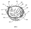
- FIG. 3 is a perspective view of the pulverizer of FIG. 1 from which an upper pulverizing casing 210 was removed.
- the pulverizer for food waste treatment apparatuses includes a pulverizing casing 200 having a hollow structure, and a pulverizing screw 100 which is installed in the pulverizing casing 200 so as to be rotatable.
- the pulverizing screw 100 pulverizes food waste input into the pulverizing casing 200.
- a drying heater may be provided on the circumferential outer surface or the upper end of the pulverizing casing 200 to dry food waste while it is being pulverized.
- the pulverizing casing 200 is a hollow unit which has an internal space of predetermined volume so as to contain a predetermined amount of food waste input thereinto.
- the pulverizing casing 200 has a spherical shape.
- the pulverizing casing 200 is divided into the upper pulverizing casing 210 and a lower pulverizing casing 220 to facilitate the installation of the pulverizing screw 100.
- the upper and lower pulverizing casings 210 and 220 be manufactured in hemispherical shapes for convenience of manufacture. Typically, they can be formed by molding to ensure the solidity.
- the upper pulverizing casing 210 includes an upper body 211 having a hemispheric shape, and a hollow cylindrical input port 216 which extends a predetermined length upwards from the upper end of the upper body 211. Furthermore, a circumferential bent portion 214 is formed by the junction between the input port 216 and the upper body 211. The bent portion 214, along with a drive blade 120, functions to cut food waste in such a way that the drive blade 120 crosses over the bent portion 214 in a state of being spaced apart from the bent portion 214 by a predetermined distance.
- the lower pulverizing casing 220 comprises a lower body 221 having a hemispheric shape.
- a circular seating depression 223 is formed in the surface of the junction of the lower pulverizing casing 220 with the upper pulverizing casing 210.
- a packing 230 is inserted into the seating depression 223. The packing 230 functions to seal the upper and lower pulverizing casings 210 and 220 after they are assembled with each other, thus preventing food waste from leaking from the pulverizing casing 200.
- first fastening parts 217 are provided around the circumference of the upper pulverizing casing 210 at positions spaced apart from each other at regular intervals
- second fastening parts 227 are provided around the circumference of the lower pulverizing casing 220 at positions spaced apart from each other at regular intervals.
- an inlet 210a is formed in the upper end of the outer surface of the upper pulverizing casing 210.
- an outlet 224 may be formed in the lower portion of the outer surface of the lower pulverizing casing 220.
- the outlet 224 may be configured so as to be openable using a door (not shown). In this case, the door may be electrically operated.
- the inlet 210a has an appropriate size and is formed in the upper end of the pulverizing casing 200 which is parallel to the support surface.
- Pulverizing ribs 222 protrude inwards from the circumferential inner surface of the pulverizing casing 200.
- the pulverizing ribs 222 function to pulverize food waste together with the pulverizing screw 100.
- the pulverizing ribs 222 are evenly distributed on the inner surfaces of the upper and lower pulverizing casings 210 and 220.
- Each pulverizing rib 222 may have a plate shape which has a predetermined thickness and sharp edges.
- the shape of the pulverizing rib 222 is not limited to the above-mentioned shape but may adopt other structures.
- the pulverizing casing 200 is made of metal which has a relatively high heat transfer rate and is manufactured by molding.
- stainless steel can be used as the material of the pulverizing casing 200.
- the pulverizing casing 200 may be coated with molybdenum to prevent remnants of food waste from getting stuck to the surface thereof.
- Molybdenum is used in anodes, as a grid or a support of an electron tube, a contact point of an electric circuit, a high-temperature resistance portion of a heat-resistance substance, a special alloy, a heating wire, coating material, etc.
- Molybdenum is mechanically very strong under conditions of very low or high temperature as well as at room temperature, and the use of molybdenum as a material applied to stainless steel is increasing lately.
- the material applied to the pulverizing casing 200 is not limited to molybdenum. That is, the pulverizing casing 200 can be coated with any material, so long as it can prevent remnants of food waste from sticking to the surface of the pulverizing casing 200. Furthermore, the pulverizing screw 100 is also coated with molybdenum such that remnants of food waste are prevented from being stuck thereto. Therefore, the treatment operation of the pulverizer can be more reliably conducted.
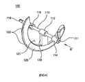
- FIG. 4 is a perspective view illustrating the pulverizing screw 100 according to the first embodiment of the present invention.
- FIG. 5 is a front view of FIG. 4 seen along the A axis.
- FIG. 6 is a right side view of FIG. 4 seen along the B axis.
- the pulverizing screw 100 includes a rotating shaft 110 and at least one drive blade 120 which extends from the rotating shaft 110 in a spiral shape.
- the drive blade 120 rotates in the spherical pulverizing casing 200 in such a manner as to maintain a state of being spaced apart from the inner surface of the pulverizing casing 200 by a predetermined distance to prevent the drive blade 120 from being impeded by the pulverizing casing 200.
- the drive blade 120 extends from a circumferential outer surface of a first end of the rotating shaft 110 in a shape surrounding the rotating shaft 110 in a clockwise or counterclockwise direction and is connected to a circumferential outer surface of a second end of the rotating shaft 110.
- the drive blade 120 surrounds the rotating shaft 110 in a spiral shape at an angle of 360°.
- a space 121 is defined between the rotating shaft 110 and the drive blade 120.
- Cylindrical rotating bodies 112, 114 and 116 are fitted over the circumferential outer surface of the rotating shaft 110.
- the medial rotating body 112 is disposed at the medial position of the rotating shaft 110.
- the first side rotating body 114 and the second side rotating body 116 are respectively disposed at the first and second ends 111 and 119 of the rotating shaft 110.
- a hole is formed through each of the rotating bodies 112, 114 and 116 along a longitudinal central axis thereof, so that the rotating shaft 110 is inserted into the holes of the rotating bodies 112, 114 and 116.
- the drive blade 120 extends from the outer surface of the first side rotating body 114 to the outer surface of the second side rotating body 116.
- the drive blade 120 is configured such that it is continuous from the outer surface of the first end of the rotating shaft 110 to the outer surface of the second end thereof.
- a support bar 130 extends from the medial rotating body 112 in the radial direction of the rotating shaft 110.
- the support bar 130 functions to stably support the drive blade 120 on the rotating shaft 110. That is, the support bar 130 is provided on the medial portion of the rotating shaft 110 and serves to support the entire pulverizing screw 100.
- the rotating shaft 110 and the rotating bodies 112, 114 and 116 may be integrally formed into a single body or, alternatively, they may be manufactured through separate processes and assembled to each other so as to be separable. In the case of the integrated structure, they may be formed by molding. In the separable structure, the production cost is reduced, and even if a part is damaged, it can be easily replaced with a new one.
- the drive blade 120 and the support bar 130 may be also integrally formed with the rotating bodies 112, 114 and 116 or, alternatively, they may be manufactured through separate processes and be separably assembled to each other. In the same manner, in the integrated structure, they may be formed by molding.
- Cutting pieces 122 are provided on an outer cutting edge of the drive blade 120. Each cutting piece 122 has a predetermined thickness and extends a predetermined length in the radial direction of the rotating shaft 110. The cutting pieces 122 serve to evenly pulverize food waste together with the inner surface of the pulverizing casing 200.
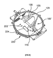
- FIG. 7 is a perspective view of the lower pulverizing casing 220 illustrating the internal construction of the pulverizer according to the present invention.
- the relationship between the drive blade 120 and the inner surface of the pulverizing casing 200 will be explained with reference to FIGS. 5 through 7 .
- the pulverizing ribs 222 are provided on the inner surface of the lower pulverizing casing 220.
- the pulverizing ribs 222 protrude inwards from the inner surface of the lower pulverizing casing 220 and are spaced apart from each other at regular intervals.
- a first depression 225a extending a predetermined distance is formed in the first pulverizing rib 222a.
- a second depression 225b extending a predetermined distance is formed in the second pulverizing rib 222b.
- several depressions 225a, 225b are formed in each pulverizing rib 222a, 222b.
- an imaginary line connecting the centers of the depressions 225a and 225b to each other forms an arc line on the circumferential inner surface of the lower body in the direction angled to the pulverizing ribs 222a and 222b. That is, as can be understood from the imaginary line 226, the first depressions 225a and the second depressions 225b are located at positions misaligned from each other.
- the cutting pieces 122 of the drive blade 120 conduct circular orbital motion along the imaginary lines 226.
- the cutting pieces 122 scrape remnants of food waste off between the pulverizing ribs 222 while the pulverizer is in operation.
- the drying operation can also be conducted while pulverizing food waste.
- the cutting pieces 122 must maintain the state of being spaced apart from the pulverizing ribs 222 by predetermined distances to avoid interference therebetween. While the drive blade 120 rotates, the outer cutting edge and cutting pieces 122 of the drive blade 120 cross over the inner surface of the pulverizing casing 200, thus pulverizing food waste.
- the medial portion of the drive blade 120 is farther from the rotating shaft 110 than are other portions.
- the distance between the drive blade 120 and the rotating shaft 110 is increased from the first end of the drive blade 120 to the medial portion thereof, and the distance therebetween is reduced again from the medial portion of the drive blade 120 to the second end thereof.
- the reference numeral 140 denotes the distance from the central axis of the rotating shaft 110 to the medial portion of the drive blade 120.
- the medial portion of the drive blade 120 holds and lifts food waste which is at the lowermost position in the lower body 221.
- food waste which is gathered on the lower portion in the pulverizing casing 200 can be continuously moved upwards by the pulverizing screw 100, thus being evenly agitated. Therefore, the pulverization and agitation of food waste in the pulverizing casing 200 can be smoothly and reliably conducted.
- the space 121 is defined between the drive blade 120 and the rotating shaft 110, when the drive blade 120 holds and lifts food waste, food waste over a proper amount naturally falls onto the lower portion of the lower body 221 through the space 121. Thereby, overload is prevented from being applied to a power supply means (not shown) for driving the drive blade 120.
- a first support mount 228 is provided on the lower pulverizing casing 220 at a first end of the junction surface thereof with the upper pulverizing casing 210
- a second support mount 229 is provided on the lower pulverizing casing 220 at a second end of the junction surface.
- the first end 111 and the second end 119 of the rotating shaft 110 are respectively inserted so as to be rotatable into insert holes formed in the first and second support mounts 228 and 229.
- a bearing may be provided in each insert hole of the first and second support mounts 228 and 229 to ensure smooth rotation.
- the power supply means (not shown), such as a motor, is connected to the second end 119 of the rotating shaft 110 to supply power thereto.
- the rotating shaft 110 receives power from the power supply means (not shown) and transmits the rotating force to the drive blade 120 such that the pulverizing screw 100 is able to rotate in the pulverizing casing 200.
- FIG. 8 is a perspective view of a pulverizing screw 100' and a lower pulverizing casing 220' of a pulverizer, according to a second embodiment of the present invention.
- the pulverizing screw 100' and the lower pulverizing casing 220' according to the second embodiment will be described in detail with reference to FIG. 8 .
- cutting notches 125 having predetermined depths are formed in an outer cutting edge of a drive blade 120 constituting the pulverizing screw 100'.
- the shape of each cutting notch 125 is determined along a circumference of an imaginary circle which is defined around the central axis of a rotating shaft 110 and has a predetermined radius.
- various numbers of cutting notches 125 may be formed in the drive blade 120 along the circumferences of imaginary concentric circles which are formed around the central axis of the rotating shaft 110 and have different radii.
- Pulverizing protrusions 222' corresponding to the cutting notches 125 of the drive blade 120 are provided on the circumferential inner surface of the lower pulverizing casing 220'.
- the pulverizing protrusions 222' are provided on at least one concentric circle at positions spaced apart from each other at regular or irregular intervals.
- the pulverizing protrusions 222' pass through the cutting notches 125.
- the pulverizing protrusions 222' are on the moving track of the cutting notches 125, food waste which is held by the cutting notches 125 can be reliably pulverized by the rotation of the pulverizing screw 100'.
- cutting edges may be formed on the inner surface of the cutting notches 125.
- a pulverizing screw having a spiral blade is installed in a spherical pulverizing casing, so that food waste input into the pulverizer can be evenly distributed and pulverized, thus enhancing the operational efficiency of the pulverizer, and reducing power consumption.
- the present invention provides a functional combination type pulverizer which takes advantage of the vertical type pulverizer and the horizontal type pulverizer, thus solving the problems of the conventional pulverizers.
- the present invention can minimize the problems of remnants of food waste being stuck to the inner surface of the pulverizer or some of the food waste remaining in the pulverizer after the food waste is discharged therefrom, which are problems which commonly result from using the conventional vertical type pulverizer and the conventional horizontal type pulverizer.
- the present invention can optimize the efficiency with which food waste is agitated, pulverized and carried.
- a load applied to the pulverizing screw can be reduced, thus enhancing the durability thereof.
- remnants of food waste which are present in the pulverizer can be minimized. Therefore, the present invention can meet the needs of consumers.
Landscapes
- Engineering & Computer Science (AREA)
- Food Science & Technology (AREA)
- Environmental & Geological Engineering (AREA)
- Health & Medical Sciences (AREA)
- Life Sciences & Earth Sciences (AREA)
- Hydrology & Water Resources (AREA)
- Public Health (AREA)
- Water Supply & Treatment (AREA)
- Crushing And Pulverization Processes (AREA)
- Processing Of Solid Wastes (AREA)
Abstract
Description
- The present invention relates to a pulverizing screw for a food waste treatment apparatus in accordance with the pre-characterizing part of claim 1.
- Generally, every house, restaurant, etc. discharges a predetermined amount of food waste everyday. Typically, such food waste is dumped after only water is removed from the food waste using a filter or the like. This conventional food waste treatment method increases the amount of food waste. If dumped food waste is not frequently treated, odors may result, with the result that the surrounding air is polluted.
- To effectively reduce and recycle food waste, the development of a food waste treatment apparatus for home use which can solve the above problems is in demand. Generally, a food waste treatment apparatus which is coupled to the domestic sink of a kitchen counter removes water from food waste and reduces the volume of the food waste through a series of processes including dehydration, cutting and drying, thus reducing the amount of food waste discharged.
- Food waste treatment apparatuses are classified into a variety of different kinds according to the method of treating food waste, and they are classified into a variety of different kinds according to the use thereof.
- Furthermore, in conventional food waste treatment apparatuses, according to the orientation of a rotating shaft and the shape of a pulverizer, they may be classified into the vertical cylindrical type pulverizer and the horizontal cylindrical type pulverizer.
- In the case of the vertical cylindrical type pulverizer, when treating food waste, a relatively low load is applied to a motor which operates a pulverizing screw to pulverize the food waste. Hence, a low-noise design can be realized. However, because the pulverizing screw is provided on the lower portion of the apparatus, food waste may not be evenly agitated or pulverized, with the result that a grain size of pulverized food waste is relatively large and food waste undesirably lumps at the central portion of the pulverizing screw and thus may not be pulverized. Furthermore, since a heater for drying food waste is provided in the lower portion of the apparatus, pulverizing and drying performance is reduced. On the other hand, the ratio of the volume occupied by the pulverizing screw is low, so that the amount of input food waste in relation to the overall size of the apparatus can be increased.
- In the horizontal cylindrical type pulverizer, because a pulverizing screw for pulverizing food waste extends for the entire length of a pulverizer, food waste can be satisfactorily agitated and pulverized. Furthermore, a heater for drying food waste is provided along the cylindrical surface of the pulverizer, so that heat can be efficiently transferred to the food waste, thus increasing the efficiency of drying. However, pulverization of food waste is focused on both ends of the pulverizing screw (that is, on both ends of the pulverizer). In addition, a large quantity of food waste is compressed by the rotation of the pulverizing screw. Thereby, an overload is applied to the pulverizing screw, with the result that it may become stopped. Furthermore, there is a disadvantage in that the amount of food waste which can be input into the pulverizer is reduced because of the large volume ratio occupied by the pulverizing screw related to the volume of the pulverizer.
- Accordingly, the present invention has been made keeping in mind the above problems occurring in the prior art, and an object of the present invention is to provide a pulverizing screw for a food waste treatment apparatus which can effectively pulverize and agitate food waste which is input into the pulverizer.
- The present invention provides a pulverizing screw of a food waste treatment apparatus having a pulverizing casing, the food waste treatment apparatus pulverizing, agitating and drying food waste input into the pulverizing casing, the pulverizing screw being provided in the pulverizing casing so as to be rotatable and including: a rotating shaft; and at least one drive blade extending from the rotating shaft in a spiral shape.
- The drive blade rotates in the pulverizing casing in such a manner as to maintain a predetermined distance between the drive blade and an inner surface of the pulverizing casing to prevent the drive blade from being impeded by the inner surface of the pulverizing casing, and the drive blade extends from a circumferential outer surface of a first end of the rotating shaft in a spiral shape surrounding the rotating shaft in a clockwise or counterclockwise direction and is connected to a circumferential outer surface of a second end of the rotating shaft.
- The drive blade may extend continuously from the outer surface of the first end of the rotating shaft to the outer surface of the second end thereof.
- Furthermore, a space is defined between the drive blade and the rotating shaft in a radial direction.
- In addition, a medial portion of the drive blade may be farther from the rotating shaft than are other portions thereof.
- The pulverizing screw may further include a support bar provided on a medial portion of the rotating shaft to support the pulverizing screw.
- As well, a cutting piece may be provided on an outer cutting edge of the drive blade in the radial direction of the rotating shaft. The cutting piece may have a predetermined thickness.
- Preferably, the pulverizing casing comprises a spherical body having a hollow space therein.
- One or more pulverizing ribs may protrude from a circumferential inner surface of the spherical body.
- The pulverizing ribs may be spaced apart from each other, and each pulverizing rib may have depressions therein. An imaginary line connecting the depressions of the pulverizing ribs to each other may form an arc line on the circumferential inner surface of the spherical body in a direction which makes an angle with the pulverizing ribs.
- Furthermore, a hollow cylindrical input port may extend from an upper portion of the spherical body. The input port may be parallel to a support surface.
- The drive blade rotates in the spherical body in such a manner as to maintain a predetermined distance between the drive blade and an inner surface of the spherical body to prevent the drive blade from being impeded by the inner surface of the spherical body.
- The drive blade may extend continuously from the outer surface of the first end of the rotating shaft to the outer surface of the second end thereof, and a medial portion of the drive blade may be farther from the rotating shaft than are other portions thereof.
- As well, a cutting piece having a predetermined thickness may be provided on an outer cutting edge of the drive blade in the radial direction of the spherical body, so that when the drive blade rotates, food waste is pulverized by reciprocal action between the cutting piece and the inner surface of the spherical body.
- One or more pulverizing ribs having predetermined lengths may protrude from a circumferential inner surface of the spherical body.
- The cutting piece may be movable on the circumferential inner surface of the spherical body along the imaginary line connecting the depressions of the pulverizing ribs.
- Furthermore, a hollow cylindrical input port may extend from an upper portion of the spherical body. The input port may be parallel to a support surface.
- In addition, an outlet may be formed in a lower end of a central portion of the spherical body. The outlet may be closed so as to be openable to discharge food waste from the spherical body.
- The outlet may be openably closed by a valve door.
- As well, a circumferential bent portion may be formed by a junction between the input port and the upper portion of the spherical body. The outer cutting edge of the drive blade may pass over the circumferential bent portion in such a manner as to maintain a predetermined distance therebetween to cut the food waste.
- Moreover, a cutting notch having a predetermined depth may be formed in an outer cutting edge of the drive blade in a radial direction of the spherical body, and a pulverizing protrusion may be provided on the inner surface of the spherical body, so that when the drive blade rotates, food waste is pulverized by reciprocal action between the cutting notch and the pulverizing protrusion.
- The above and other objects, features and advantages of the present invention will be more clearly understood from the following detailed description taken in conjunction with the accompanying drawings, in which:
-
FIG. 1 is a partially broken perspective view of a pulverizer for a food waste treatment apparatus, according to a first embodiment of the present invention; -
FIG. 2 is an exploded perspective view of the pulverizer ofFIG. 1 ; -
FIG. 3 is a perspective view of the pulverizer ofFIG. 1 from which an upper pulverizing casing was removed; -
FIG. 4 is a perspective view illustrating a pulverizing screw according to the first embodiment of the present invention; -
FIG. 5 is a front view ofFIG. 4 seen along the A axis; -
FIG. 6 is a right side view ofFIG. 4 seen along the B axis; -
FIG. 7 is a perspective view of a lower pulverizing casing which illustrates the internal construction of the pulverizer according to the present invention; and -
FIG. 8 is a perspective view of a pulverizing screw and a lower pulverizing casing of a pulverizer, according to a second embodiment of the present invention. - Hereinafter, a pulverizing screw, a pulverizing casing and a pulverizer for food waste treatment apparatuses having the same according to preferred embodiments of the present invention will be described in detail with reference to the attached drawings.
- A first embodiment of the present invention will be described in detail with reference to the related drawings.
-
FIG. 1 is a partially broken perspective view of a pulverizer for food waste treatment apparatuses, according to the first embodiment of the present invention.FIG. 2 is an exploded perspective view of the pulverizer ofFIG. 1 .FIG. 3 is a perspective view of the pulverizer ofFIG. 1 from which anupper pulverizing casing 210 was removed. - Referring to
FIGS. 1 through 3 , the pulverizer for food waste treatment apparatuses according to the first embodiment of the present invention includes a pulverizingcasing 200 having a hollow structure, and a pulverizingscrew 100 which is installed in the pulverizingcasing 200 so as to be rotatable. - In the pulverizer for food waste treatment apparatuses according to the present invention, the pulverizing
screw 100 pulverizes food waste input into the pulverizingcasing 200. A drying heater may be provided on the circumferential outer surface or the upper end of the pulverizingcasing 200 to dry food waste while it is being pulverized. - The pulverizing
casing 200 is a hollow unit which has an internal space of predetermined volume so as to contain a predetermined amount of food waste input thereinto. Preferably, the pulverizingcasing 200 has a spherical shape. The pulverizingcasing 200 is divided into theupper pulverizing casing 210 and alower pulverizing casing 220 to facilitate the installation of the pulverizingscrew 100. Furthermore, it is preferable that the upper and lower pulverizingcasings - The
upper pulverizing casing 210 includes anupper body 211 having a hemispheric shape, and a hollowcylindrical input port 216 which extends a predetermined length upwards from the upper end of theupper body 211. Furthermore, a circumferentialbent portion 214 is formed by the junction between theinput port 216 and theupper body 211. Thebent portion 214, along with adrive blade 120, functions to cut food waste in such a way that thedrive blade 120 crosses over thebent portion 214 in a state of being spaced apart from thebent portion 214 by a predetermined distance. - The
lower pulverizing casing 220 comprises alower body 221 having a hemispheric shape. Acircular seating depression 223 is formed in the surface of the junction of thelower pulverizing casing 220 with theupper pulverizing casing 210. A packing 230 is inserted into theseating depression 223. The packing 230 functions to seal the upper and lower pulverizingcasings casing 200. - On the junction between the upper and lower pulverizing
casings first fastening parts 217 are provided around the circumference of theupper pulverizing casing 210 at positions spaced apart from each other at regular intervals, andsecond fastening parts 227 are provided around the circumference of thelower pulverizing casing 220 at positions spaced apart from each other at regular intervals. To couple the upper and lower pulverizingcasings fastening parts - Meanwhile, an
inlet 210a is formed in the upper end of the outer surface of theupper pulverizing casing 210. As necessary, anoutlet 224 may be formed in the lower portion of the outer surface of thelower pulverizing casing 220. Theoutlet 224 may be configured so as to be openable using a door (not shown). In this case, the door may be electrically operated. - To enable a user to easily input dehydrated and cut food waste into the pulverizing
casing 200, theinlet 210a has an appropriate size and is formed in the upper end of the pulverizingcasing 200 which is parallel to the support surface. Pulverizingribs 222 protrude inwards from the circumferential inner surface of the pulverizingcasing 200. The pulverizingribs 222 function to pulverize food waste together with the pulverizingscrew 100. The pulverizingribs 222 are evenly distributed on the inner surfaces of the upper and lower pulverizingcasings rib 222 may have a plate shape which has a predetermined thickness and sharp edges. The shape of the pulverizingrib 222 is not limited to the above-mentioned shape but may adopt other structures. - Preferably, the pulverizing
casing 200 is made of metal which has a relatively high heat transfer rate and is manufactured by molding. Typically, stainless steel can be used as the material of the pulverizingcasing 200. More preferably, the pulverizingcasing 200 may be coated with molybdenum to prevent remnants of food waste from getting stuck to the surface thereof. Molybdenum is used in anodes, as a grid or a support of an electron tube, a contact point of an electric circuit, a high-temperature resistance portion of a heat-resistance substance, a special alloy, a heating wire, coating material, etc. Molybdenum is mechanically very strong under conditions of very low or high temperature as well as at room temperature, and the use of molybdenum as a material applied to stainless steel is increasing lately. - Here, of course, the material applied to the pulverizing
casing 200 is not limited to molybdenum. That is, the pulverizingcasing 200 can be coated with any material, so long as it can prevent remnants of food waste from sticking to the surface of the pulverizingcasing 200. Furthermore, the pulverizingscrew 100 is also coated with molybdenum such that remnants of food waste are prevented from being stuck thereto. Therefore, the treatment operation of the pulverizer can be more reliably conducted. -
FIG. 4 is a perspective view illustrating the pulverizingscrew 100 according to the first embodiment of the present invention.FIG. 5 is a front view ofFIG. 4 seen along the A axis.FIG. 6 is a right side view ofFIG. 4 seen along the B axis. - Hereinafter, the pulverizing
screw 100 which is the critical part of the present invention will be described in detail with reference toFIGS. 4 through 6 . - The pulverizing
screw 100 includes arotating shaft 110 and at least onedrive blade 120 which extends from therotating shaft 110 in a spiral shape. Thedrive blade 120 rotates in thespherical pulverizing casing 200 in such a manner as to maintain a state of being spaced apart from the inner surface of the pulverizingcasing 200 by a predetermined distance to prevent thedrive blade 120 from being impeded by the pulverizingcasing 200. In detail, thedrive blade 120 extends from a circumferential outer surface of a first end of therotating shaft 110 in a shape surrounding therotating shaft 110 in a clockwise or counterclockwise direction and is connected to a circumferential outer surface of a second end of therotating shaft 110. In the embodiment, thedrive blade 120 surrounds therotating shaft 110 in a spiral shape at an angle of 360°. In the installation of thedrive blade 120, aspace 121 is defined between therotating shaft 110 and thedrive blade 120. - Cylindrical
rotating bodies rotating shaft 110. The medialrotating body 112 is disposed at the medial position of therotating shaft 110. The firstside rotating body 114 and the secondside rotating body 116 are respectively disposed at the first and second ends 111 and 119 of therotating shaft 110. A hole is formed through each of therotating bodies rotating shaft 110 is inserted into the holes of therotating bodies - The
drive blade 120 extends from the outer surface of the firstside rotating body 114 to the outer surface of the secondside rotating body 116. In other words, thedrive blade 120 is configured such that it is continuous from the outer surface of the first end of therotating shaft 110 to the outer surface of the second end thereof. Asupport bar 130 extends from the medialrotating body 112 in the radial direction of therotating shaft 110. Thesupport bar 130 functions to stably support thedrive blade 120 on therotating shaft 110. That is, thesupport bar 130 is provided on the medial portion of therotating shaft 110 and serves to support the entire pulverizingscrew 100. - The
rotating shaft 110 and therotating bodies drive blade 120 and thesupport bar 130 may be also integrally formed with therotating bodies - Cutting
pieces 122 are provided on an outer cutting edge of thedrive blade 120. Each cuttingpiece 122 has a predetermined thickness and extends a predetermined length in the radial direction of therotating shaft 110. The cuttingpieces 122 serve to evenly pulverize food waste together with the inner surface of the pulverizingcasing 200. -
FIG. 7 is a perspective view of thelower pulverizing casing 220 illustrating the internal construction of the pulverizer according to the present invention. Hereinafter, the relationship between thedrive blade 120 and the inner surface of the pulverizingcasing 200 will be explained with reference toFIGS. 5 through 7 . - Referring to
FIG. 7 , the pulverizingribs 222 are provided on the inner surface of thelower pulverizing casing 220. Preferably, the pulverizingribs 222 protrude inwards from the inner surface of thelower pulverizing casing 220 and are spaced apart from each other at regular intervals. - Two adjacent pulverizing
ribs first depression 225a extending a predetermined distance is formed in thefirst pulverizing rib 222a. Asecond depression 225b extending a predetermined distance is formed in thesecond pulverizing rib 222b. Preferably,several depressions rib reference numeral 226, an imaginary line connecting the centers of thedepressions ribs imaginary line 226, thefirst depressions 225a and thesecond depressions 225b are located at positions misaligned from each other. - When the pulverizing
screw 100 rotates in the pulverizingcasing 200, the cuttingpieces 122 of thedrive blade 120 conduct circular orbital motion along theimaginary lines 226. In this process, the cuttingpieces 122 scrape remnants of food waste off between the pulverizingribs 222 while the pulverizer is in operation. Furthermore, the drying operation can also be conducted while pulverizing food waste. Thus, because the cuttingpieces 122 scrape food waste while or after the food waste is dried, the food waste which has been stuck to the inner surface of the pulverizingcasing 200 can more easily and reliably removed therefrom. - The cutting
pieces 122 must maintain the state of being spaced apart from the pulverizingribs 222 by predetermined distances to avoid interference therebetween. While thedrive blade 120 rotates, the outer cutting edge and cuttingpieces 122 of thedrive blade 120 cross over the inner surface of the pulverizingcasing 200, thus pulverizing food waste. - As shown in
FIGS. 5 and6 , the medial portion of thedrive blade 120 is farther from therotating shaft 110 than are other portions. In other words, with regard to the shape in which thedrive blade 120 extends from therotating shaft 110 in a spiral shape, the distance between thedrive blade 120 and therotating shaft 110 is increased from the first end of thedrive blade 120 to the medial portion thereof, and the distance therebetween is reduced again from the medial portion of thedrive blade 120 to the second end thereof. In the drawing, thereference numeral 140 denotes the distance from the central axis of therotating shaft 110 to the medial portion of thedrive blade 120. - Due to the structural characteristics of the pulverizing
screw 100, when the pulverizingscrew 100 rotates, the medial portion of thedrive blade 120 holds and lifts food waste which is at the lowermost position in thelower body 221. As such, in the process of treating food waste, food waste which is gathered on the lower portion in the pulverizingcasing 200 can be continuously moved upwards by the pulverizingscrew 100, thus being evenly agitated. Therefore, the pulverization and agitation of food waste in the pulverizingcasing 200 can be smoothly and reliably conducted. Furthermore, because thespace 121 is defined between thedrive blade 120 and therotating shaft 110, when thedrive blade 120 holds and lifts food waste, food waste over a proper amount naturally falls onto the lower portion of thelower body 221 through thespace 121. Thereby, overload is prevented from being applied to a power supply means (not shown) for driving thedrive blade 120. - Meanwhile, to install the pulverizing
screw 100 in thelower pulverizing casing 220, afirst support mount 228 is provided on thelower pulverizing casing 220 at a first end of the junction surface thereof with theupper pulverizing casing 210, and asecond support mount 229 is provided on thelower pulverizing casing 220 at a second end of the junction surface. Thefirst end 111 and thesecond end 119 of therotating shaft 110 are respectively inserted so as to be rotatable into insert holes formed in the first and second support mounts 228 and 229. A bearing may be provided in each insert hole of the first and second support mounts 228 and 229 to ensure smooth rotation. In addition, the power supply means (not shown), such as a motor, is connected to thesecond end 119 of therotating shaft 110 to supply power thereto. - The
rotating shaft 110 receives power from the power supply means (not shown) and transmits the rotating force to thedrive blade 120 such that the pulverizingscrew 100 is able to rotate in the pulverizingcasing 200. -
FIG. 8 is a perspective view of a pulverizing screw 100' and a lower pulverizing casing 220' of a pulverizer, according to a second embodiment of the present invention. Hereinafter, the pulverizing screw 100' and the lower pulverizing casing 220' according to the second embodiment will be described in detail with reference toFIG. 8 . - In the second embodiment, cutting
notches 125 having predetermined depths are formed in an outer cutting edge of adrive blade 120 constituting the pulverizing screw 100'. The shape of each cuttingnotch 125 is determined along a circumference of an imaginary circle which is defined around the central axis of arotating shaft 110 and has a predetermined radius. In other words, according to the intended purposes of a designer, various numbers of cuttingnotches 125 may be formed in thedrive blade 120 along the circumferences of imaginary concentric circles which are formed around the central axis of therotating shaft 110 and have different radii. - Pulverizing protrusions 222' corresponding to the cutting
notches 125 of thedrive blade 120 are provided on the circumferential inner surface of the lower pulverizing casing 220'. The pulverizing protrusions 222' are provided on at least one concentric circle at positions spaced apart from each other at regular or irregular intervals. - When the pulverizing screw 100' rotates in the pulverizing
casing 200, the pulverizing protrusions 222' pass through the cuttingnotches 125. As such, because the pulverizing protrusions 222' are on the moving track of the cuttingnotches 125, food waste which is held by the cuttingnotches 125 can be reliably pulverized by the rotation of the pulverizing screw 100'. Preferably, cutting edges may be formed on the inner surface of the cuttingnotches 125. - As described above, in the pulverizer for food waste treatment apparatuses according to the present invention, a pulverizing screw having a spiral blade is installed in a spherical pulverizing casing, so that food waste input into the pulverizer can be evenly distributed and pulverized, thus enhancing the operational efficiency of the pulverizer, and reducing power consumption.
- Furthermore, the present invention provides a functional combination type pulverizer which takes advantage of the vertical type pulverizer and the horizontal type pulverizer, thus solving the problems of the conventional pulverizers. In other words, the present invention can minimize the problems of remnants of food waste being stuck to the inner surface of the pulverizer or some of the food waste remaining in the pulverizer after the food waste is discharged therefrom, which are problems which commonly result from using the conventional vertical type pulverizer and the conventional horizontal type pulverizer.
- In brief, the present invention can optimize the efficiency with which food waste is agitated, pulverized and carried. In addition, a load applied to the pulverizing screw can be reduced, thus enhancing the durability thereof. As well, remnants of food waste which are present in the pulverizer can be minimized. Therefore, the present invention can meet the needs of consumers.
- Although the preferred embodiments of the present invention have been disclosed for illustrative purposes, those skilled in the art will appreciate that various modifications, additions and substitutions are possible, without departing from the scope the invention as disclosed in the accompanying claims.
Claims (5)
- A pulverizing screw (100) suitable to be used in a food waste treatment apparatus having a pulverizing casing (200),the food waste treatment apparatus pulverizing, agitating and the drying food waste input into the pulverizing casing, the pulverizing screw (100) being provided in the pulverizing casing (200) so as to be rotatable and comprising:a rotating shaft (110); andat least one drive blade (120) extending from the rotating shaft (110) in a spiral shape,wherein the drive blade (120) rotates in the pulverizing casing (200) in such a manner as to maintain a predetermined distance between the drive blade (120) and an inner surface of the pulverizing casing (200) to prevent the drive blade (120) from being impeded by the inner surface of the pulverizing casing,characterized in that the drive blade (120) extends from a circumferential outer surface of a first end (111) of the rotating shaft in a spiral shape surrounding the rotating shaft (110) in a clockwise or counterclockwise direction and is connected to a circumferential outer surface of a second end (119) of the rotating shaft (110),
wherein a space (121) is defined between the drive blade (120) and the rotating shaft (110) in a radial direction. - The pulverizing screw as set forth in claim 1, wherein the drive blade (120) extends continuously from the outer surface of the first end (111) of the rotating shaft (110) to the outer surface of the second end (119) thereof.
- The pulverizing screw as set forth on claim 2, wherein a medial portion of the drive blade (120) is farther from the rotating shaft (110) than are other portions thereof.
- The pulverizing screw as set forth in claim 3, further comprising:a support bar (130) provided on a medial portion of the rotating shaft (110) to support the pulverizing screw (100).
- The pulverizing screw as set forth in claim 3, wherein a cutting piece (122) is provided on an outer cutting edge of the drive blade (120) in the radial direction of the rotating shaft (110), the cutting piece (122) having a predetermined thickness.
Priority Applications (1)
| Application Number | Priority Date | Filing Date | Title |
|---|---|---|---|
| EP11001016A EP2317019A2 (en) | 2008-10-14 | 2009-06-30 | Pulverizing casing and pulverizer for food waste treatment apparatus having the same |
Applications Claiming Priority (1)
| Application Number | Priority Date | Filing Date | Title |
|---|---|---|---|
| KR1020080100874A KR101108738B1 (en) | 2008-10-14 | 2008-10-14 | Pulverizing Screw, Pulverizing Drum and A Pulverizer of Food Treatment System having the Pulverizing Screw and the Pulverizing Drum |
Related Child Applications (1)
| Application Number | Title | Priority Date | Filing Date |
|---|---|---|---|
| EP11001016.2 Division-Into | 2011-02-08 |
Publications (3)
| Publication Number | Publication Date |
|---|---|
| EP2177674A2 EP2177674A2 (en) | 2010-04-21 |
| EP2177674A3 EP2177674A3 (en) | 2010-07-21 |
| EP2177674B1 true EP2177674B1 (en) | 2011-10-19 |
Family
ID=41668386
Family Applications (2)
| Application Number | Title | Priority Date | Filing Date |
|---|---|---|---|
| EP09008586A Not-in-force EP2177674B1 (en) | 2008-10-14 | 2009-06-30 | Pulverizing screw for food waste treatment apparatus |
| EP11001016A Withdrawn EP2317019A2 (en) | 2008-10-14 | 2009-06-30 | Pulverizing casing and pulverizer for food waste treatment apparatus having the same |
Family Applications After (1)
| Application Number | Title | Priority Date | Filing Date |
|---|---|---|---|
| EP11001016A Withdrawn EP2317019A2 (en) | 2008-10-14 | 2009-06-30 | Pulverizing casing and pulverizer for food waste treatment apparatus having the same |
Country Status (6)
| Country | Link |
|---|---|
| US (2) | US8191811B2 (en) |
| EP (2) | EP2177674B1 (en) |
| JP (1) | JP5128549B2 (en) |
| KR (1) | KR101108738B1 (en) |
| CN (1) | CN101722091B (en) |
| AT (1) | ATE529573T1 (en) |
Families Citing this family (17)
| Publication number | Priority date | Publication date | Assignee | Title |
|---|---|---|---|---|
| KR101049350B1 (en) * | 2008-10-14 | 2011-07-13 | 웅진코웨이주식회사 | Grinding Furnace Of Food Processor |
| KR101069240B1 (en) * | 2011-03-08 | 2011-10-04 | 주식회사 세인이엔지 | Food Waste Disposal Device |
| CN102813468B (en) * | 2011-11-01 | 2015-11-18 | 宁波厨聚厨房科技有限公司 | Mill |
| EP2628542A1 (en) * | 2012-02-15 | 2013-08-21 | Ta Ya Kitchen Utensil Co., Ltd. | Grinder assembly for a waste disposal device |
| ITMI20120836A1 (en) * | 2012-05-15 | 2013-11-16 | Rinaldo Franceschini | DEHYDRATION EQUIPMENT FOR CENTRIFUGATION OF FOOD WASTE |
| CN203076044U (en) * | 2013-02-20 | 2013-07-24 | 东莞合力电器制品有限公司 | Cutting tool of food processor |
| KR101432650B1 (en) | 2014-01-03 | 2014-08-25 | 인덕대학교 산학협력단 | The Crushing Device for Disposing of Food waste |
| US9615604B2 (en) | 2014-02-06 | 2017-04-11 | David Russick | Food waste dehydrator |
| KR101669921B1 (en) | 2015-12-17 | 2016-10-31 | 정창현 | Polymerization device for stirring polymer and cleaning residual monomer easily |
| JP2018117102A (en) * | 2017-01-20 | 2018-07-26 | ソニーセミコンダクタソリューションズ株式会社 | Semiconductor device |
| CN107021789A (en) * | 2017-06-07 | 2017-08-08 | 绿地集团森茂园林有限公司 | A kind of garden waste material machine |
| CN107702554B (en) * | 2017-10-30 | 2024-09-03 | 上海肩并肩电子科技有限公司 | Intelligent cement kiln inner cleaning system |
| CN108745630B (en) * | 2018-06-13 | 2019-10-18 | 合肥久多农业科技有限公司 | An agricultural recycling fertilizer grinder |
| CN109113142A (en) * | 2018-10-18 | 2019-01-01 | 合肥峰腾节能科技有限公司 | A kind of environment-protection wastewater pretreatment unit for kitchen sink |
| CN112452471B (en) * | 2020-11-10 | 2022-09-27 | 湖南玉和园食品有限公司 | Automatic food processing machinery's crushing mechanism |
| CN115351031B (en) * | 2022-08-16 | 2024-01-26 | 长沙雷邦环保科技有限公司 | Multifunctional kitchen waste treatment equipment and kitchen waste treatment method |
| CN116689116B (en) * | 2023-08-05 | 2024-06-07 | 株洲辉文工贸有限公司 | Material batch conveying crusher |
Family Cites Families (30)
| Publication number | Priority date | Publication date | Assignee | Title |
|---|---|---|---|---|
| US1732775A (en) | 1929-10-22 | Refuse dispenser | ||
| GB602862A (en) | 1946-01-12 | 1948-06-03 | British Thomson Houston Co Ltd | Improvements in waste disposal apparatus for attachment to a sink |
| JPS5746952A (en) * | 1980-09-04 | 1982-03-17 | Chisso Corp | 4'-(beta-alkyloxyethoxy)-4-cyanobiphenyl |
| US4983046A (en) * | 1987-09-04 | 1991-01-08 | Nisshin Flour Milling Co., Ltd. | Mixer |
| JP2987461B2 (en) * | 1990-04-20 | 1999-12-06 | 伸洋産業株式会社 | Garbage decomposition equipment |
| JPH078031Y2 (en) * | 1990-07-23 | 1995-03-01 | 株式会社クボタ | Grinding equipment |
| FR2666247B1 (en) | 1990-08-28 | 1992-11-27 | Audureau Sa | SCREW MIXER. |
| US5148999A (en) * | 1991-01-11 | 1992-09-22 | Farm Shop, Inc. | Animal feed mixing system |
| JPH054885A (en) * | 1991-06-26 | 1993-01-14 | Yanmar Agricult Equip Co Ltd | Fermenter for household garbage processing machine |
| KR930006962A (en) | 1991-09-25 | 1993-04-22 | 이헌조 | Structure of MESFET |
| KR930006962Y1 (en) * | 1991-12-17 | 1993-10-11 | 이주헌 | Fish Grinding Device for Fish Feed Maker |
| ATE144298T1 (en) * | 1992-12-05 | 1996-11-15 | Voith Gmbh J M | WASTE PAPER DIGESTER |
| JPH0775769A (en) * | 1993-09-08 | 1995-03-20 | Kinpachi Fujimura | Garbage processing equipment |
| JP3009489U (en) * | 1994-09-26 | 1995-04-04 | 株式会社ヨシダ鉄工 | Garbage processing equipment |
| JPH11128897A (en) * | 1996-11-28 | 1999-05-18 | Denso Corp | Garbage disposal equipment |
| CN2294113Y (en) * | 1997-04-07 | 1998-10-14 | 吕清源 | Universal disintegrating machine |
| CN2323869Y (en) * | 1997-12-17 | 1999-06-16 | 严亨远 | Garbage coarse crusher |
| JPH11285678A (en) * | 1998-04-01 | 1999-10-19 | Dainichi Co Ltd | Garbage processing machine |
| CN1255408A (en) * | 1998-11-30 | 2000-06-07 | 胡元强 | Knife-tooth cutting type breaking method for destroyer and its apparatus |
| JP3422947B2 (en) * | 1999-02-19 | 2003-07-07 | 株式会社テクニカルスチール | Garbage decomposition equipment |
| JP2000317420A (en) | 1999-05-12 | 2000-11-21 | Araco Corp | Garbage processing equipment |
| JP2001113194A (en) * | 1999-10-20 | 2001-04-24 | Ona Tekko:Kk | Grinding stirrer |
| JP2001145839A (en) * | 1999-11-22 | 2001-05-29 | Morishita Kikai Kk | Garbage crusher |
| KR200264897Y1 (en) * | 2001-10-30 | 2002-02-25 | 주식회사 가이아 | Agitator |
| KR100468599B1 (en) * | 2002-01-22 | 2005-02-02 | (주)선보정밀 | Apparatus for disposing garbage of food |
| KR100498249B1 (en) | 2002-04-12 | 2005-07-01 | 주식회사 가이아 | Agitator for disposal of food or orgarnic waste |
| KR100638372B1 (en) * | 2005-02-01 | 2006-10-25 | 김영기 | Food waste treatment device |
| JP4701351B2 (en) * | 2005-04-28 | 2011-06-15 | 国立大学法人岐阜大学 | Organic waste treatment equipment |
| CN2930860Y (en) * | 2006-03-21 | 2007-08-08 | 黎欧 | Crushing apparatus of kitchen waste treating machine |
| KR101049350B1 (en) * | 2008-10-14 | 2011-07-13 | 웅진코웨이주식회사 | Grinding Furnace Of Food Processor |
-
2008
- 2008-10-14 KR KR1020080100874A patent/KR101108738B1/en active Active
-
2009
- 2009-06-29 US US12/459,301 patent/US8191811B2/en not_active Expired - Fee Related
- 2009-06-30 EP EP09008586A patent/EP2177674B1/en not_active Not-in-force
- 2009-06-30 EP EP11001016A patent/EP2317019A2/en not_active Withdrawn
- 2009-06-30 JP JP2009155153A patent/JP5128549B2/en not_active Expired - Fee Related
- 2009-06-30 AT AT09008586T patent/ATE529573T1/en not_active IP Right Cessation
- 2009-06-30 CN CN2009101462948A patent/CN101722091B/en not_active Expired - Fee Related
-
2012
- 2012-05-08 US US13/466,737 patent/US8342436B2/en not_active Expired - Fee Related
Also Published As
| Publication number | Publication date |
|---|---|
| CN101722091A (en) | 2010-06-09 |
| KR101108738B1 (en) | 2012-03-14 |
| KR20100041610A (en) | 2010-04-22 |
| US8342436B2 (en) | 2013-01-01 |
| EP2177674A3 (en) | 2010-07-21 |
| US8191811B2 (en) | 2012-06-05 |
| US20100090046A1 (en) | 2010-04-15 |
| ATE529573T1 (en) | 2011-11-15 |
| CN101722091B (en) | 2013-03-13 |
| EP2177674A2 (en) | 2010-04-21 |
| JP2010094662A (en) | 2010-04-30 |
| US20120217332A1 (en) | 2012-08-30 |
| JP5128549B2 (en) | 2013-01-23 |
| EP2317019A2 (en) | 2011-05-04 |
Similar Documents
| Publication | Publication Date | Title |
|---|---|---|
| US8342436B2 (en) | Pulverizing screw, pulverizing casing and pulverizer for food waste treatment apparatus having the same | |
| EP2351889B1 (en) | Pulverizer for food waste treatment apparatus | |
| US8267339B2 (en) | Transfer unit having transfer rotor and food waste treatment apparatus using the same | |
| KR101418605B1 (en) | A drying furnace of a food processor equipped with a rotating screw | |
| JP5102391B2 (en) | Valve discharge device | |
| KR20080003682U (en) | Rotary blade for countertop food waste | |
| KR101578207B1 (en) | Pulverizing Screw and A Pulverizer of Food Treatment System having the Pulverizing Screw | |
| WO2009116709A1 (en) | Valve exhausting apparatus and a drier of food treatment system having it | |
| KR20100042177A (en) | A pulverizer of garbage disposing apparatus | |
| KR101176304B1 (en) | Pulverizing Screw, Pulverizing Drum and A Pulverizer of Food Treatment System having the Pulverizing Screw and the Pulverizing Drum | |
| KR101511750B1 (en) | Mixing and drying part for food disposer and food disposer including it | |
| KR101410140B1 (en) | Pulverizing Screw and A Pulverizer of Food Treatment System | |
| KR101711578B1 (en) | Pulverization structure of food waste disposer | |
| KR101511763B1 (en) | Mixing and drying part for food disposer and food disposer including it | |
| KR101511760B1 (en) | Mixing and drying part for food disposer and food disposer including it | |
| KR101175047B1 (en) | Pulverizing Screw and A Pulverizer of Food Treatment System | |
| KR20100036821A (en) | A drier of food treatment system | |
| JP2007093184A (en) | Food residue dryer, hern |
Legal Events
| Date | Code | Title | Description |
|---|---|---|---|
| PUAI | Public reference made under article 153(3) epc to a published international application that has entered the european phase |
Free format text: ORIGINAL CODE: 0009012 |
|
| 17P | Request for examination filed |
Effective date: 20100112 |
|
| AK | Designated contracting states |
Kind code of ref document: A2 Designated state(s): AT BE BG CH CY CZ DE DK EE ES FI FR GB GR HR HU IE IS IT LI LT LU LV MC MK MT NL NO PL PT RO SE SI SK TR |
|
| AX | Request for extension of the european patent |
Extension state: AL BA RS |
|
| PUAL | Search report despatched |
Free format text: ORIGINAL CODE: 0009013 |
|
| AK | Designated contracting states |
Kind code of ref document: A3 Designated state(s): AT BE BG CH CY CZ DE DK EE ES FI FR GB GR HR HU IE IS IT LI LT LU LV MC MK MT NL NO PL PT RO SE SI SK TR |
|
| AX | Request for extension of the european patent |
Extension state: AL BA RS |
|
| GRAP | Despatch of communication of intention to grant a patent |
Free format text: ORIGINAL CODE: EPIDOSNIGR1 |
|
| RIC1 | Information provided on ipc code assigned before grant |
Ipc: B02C 18/00 20060101ALN20110502BHEP Ipc: E03C 1/266 20060101AFI20110502BHEP |
|
| RTI1 | Title (correction) |
Free format text: PULVERIZING SCREW FOR FOOD WASTE TREATMENT APPARATUS |
|
| GRAS | Grant fee paid |
Free format text: ORIGINAL CODE: EPIDOSNIGR3 |
|
| GRAA | (expected) grant |
Free format text: ORIGINAL CODE: 0009210 |
|
| AK | Designated contracting states |
Kind code of ref document: B1 Designated state(s): AT BE BG CH CY CZ DE DK EE ES FI FR GB GR HR HU IE IS IT LI LT LU LV MC MK MT NL NO PL PT RO SE SI SK TR |
|
| REG | Reference to a national code |
Ref country code: GB Ref legal event code: FG4D |
|
| REG | Reference to a national code |
Ref country code: CH Ref legal event code: EP |
|
| REG | Reference to a national code |
Ref country code: IE Ref legal event code: FG4D |
|
| REG | Reference to a national code |
Ref country code: DE Ref legal event code: R096 Ref document number: 602009003123 Country of ref document: DE Effective date: 20120119 |
|
| REG | Reference to a national code |
Ref country code: NL Ref legal event code: VDEP Effective date: 20111019 |
|
| LTIE | Lt: invalidation of european patent or patent extension |
Effective date: 20111019 |
|
| REG | Reference to a national code |
Ref country code: AT Ref legal event code: MK05 Ref document number: 529573 Country of ref document: AT Kind code of ref document: T Effective date: 20111019 |
|
| PG25 | Lapsed in a contracting state [announced via postgrant information from national office to epo] |
Ref country code: LT Free format text: LAPSE BECAUSE OF FAILURE TO SUBMIT A TRANSLATION OF THE DESCRIPTION OR TO PAY THE FEE WITHIN THE PRESCRIBED TIME-LIMIT Effective date: 20111019 Ref country code: IS Free format text: LAPSE BECAUSE OF FAILURE TO SUBMIT A TRANSLATION OF THE DESCRIPTION OR TO PAY THE FEE WITHIN THE PRESCRIBED TIME-LIMIT Effective date: 20120219 Ref country code: NO Free format text: LAPSE BECAUSE OF FAILURE TO SUBMIT A TRANSLATION OF THE DESCRIPTION OR TO PAY THE FEE WITHIN THE PRESCRIBED TIME-LIMIT Effective date: 20120119 Ref country code: BE Free format text: LAPSE BECAUSE OF FAILURE TO SUBMIT A TRANSLATION OF THE DESCRIPTION OR TO PAY THE FEE WITHIN THE PRESCRIBED TIME-LIMIT Effective date: 20111019 |
|
| PG25 | Lapsed in a contracting state [announced via postgrant information from national office to epo] |
Ref country code: SI Free format text: LAPSE BECAUSE OF FAILURE TO SUBMIT A TRANSLATION OF THE DESCRIPTION OR TO PAY THE FEE WITHIN THE PRESCRIBED TIME-LIMIT Effective date: 20111019 Ref country code: GR Free format text: LAPSE BECAUSE OF FAILURE TO SUBMIT A TRANSLATION OF THE DESCRIPTION OR TO PAY THE FEE WITHIN THE PRESCRIBED TIME-LIMIT Effective date: 20120120 Ref country code: LV Free format text: LAPSE BECAUSE OF FAILURE TO SUBMIT A TRANSLATION OF THE DESCRIPTION OR TO PAY THE FEE WITHIN THE PRESCRIBED TIME-LIMIT Effective date: 20111019 Ref country code: HR Free format text: LAPSE BECAUSE OF FAILURE TO SUBMIT A TRANSLATION OF THE DESCRIPTION OR TO PAY THE FEE WITHIN THE PRESCRIBED TIME-LIMIT Effective date: 20111019 Ref country code: NL Free format text: LAPSE BECAUSE OF FAILURE TO SUBMIT A TRANSLATION OF THE DESCRIPTION OR TO PAY THE FEE WITHIN THE PRESCRIBED TIME-LIMIT Effective date: 20111019 Ref country code: PT Free format text: LAPSE BECAUSE OF FAILURE TO SUBMIT A TRANSLATION OF THE DESCRIPTION OR TO PAY THE FEE WITHIN THE PRESCRIBED TIME-LIMIT Effective date: 20120220 Ref country code: SE Free format text: LAPSE BECAUSE OF FAILURE TO SUBMIT A TRANSLATION OF THE DESCRIPTION OR TO PAY THE FEE WITHIN THE PRESCRIBED TIME-LIMIT Effective date: 20111019 |
|
| PG25 | Lapsed in a contracting state [announced via postgrant information from national office to epo] |
Ref country code: CY Free format text: LAPSE BECAUSE OF FAILURE TO SUBMIT A TRANSLATION OF THE DESCRIPTION OR TO PAY THE FEE WITHIN THE PRESCRIBED TIME-LIMIT Effective date: 20111019 |
|
| PG25 | Lapsed in a contracting state [announced via postgrant information from national office to epo] |
Ref country code: DK Free format text: LAPSE BECAUSE OF FAILURE TO SUBMIT A TRANSLATION OF THE DESCRIPTION OR TO PAY THE FEE WITHIN THE PRESCRIBED TIME-LIMIT Effective date: 20111019 Ref country code: EE Free format text: LAPSE BECAUSE OF FAILURE TO SUBMIT A TRANSLATION OF THE DESCRIPTION OR TO PAY THE FEE WITHIN THE PRESCRIBED TIME-LIMIT Effective date: 20111019 Ref country code: BG Free format text: LAPSE BECAUSE OF FAILURE TO SUBMIT A TRANSLATION OF THE DESCRIPTION OR TO PAY THE FEE WITHIN THE PRESCRIBED TIME-LIMIT Effective date: 20120119 Ref country code: SK Free format text: LAPSE BECAUSE OF FAILURE TO SUBMIT A TRANSLATION OF THE DESCRIPTION OR TO PAY THE FEE WITHIN THE PRESCRIBED TIME-LIMIT Effective date: 20111019 Ref country code: CZ Free format text: LAPSE BECAUSE OF FAILURE TO SUBMIT A TRANSLATION OF THE DESCRIPTION OR TO PAY THE FEE WITHIN THE PRESCRIBED TIME-LIMIT Effective date: 20111019 |
|
| PLBE | No opposition filed within time limit |
Free format text: ORIGINAL CODE: 0009261 |
|
| STAA | Information on the status of an ep patent application or granted ep patent |
Free format text: STATUS: NO OPPOSITION FILED WITHIN TIME LIMIT |
|
| PG25 | Lapsed in a contracting state [announced via postgrant information from national office to epo] |
Ref country code: PL Free format text: LAPSE BECAUSE OF FAILURE TO SUBMIT A TRANSLATION OF THE DESCRIPTION OR TO PAY THE FEE WITHIN THE PRESCRIBED TIME-LIMIT Effective date: 20111019 Ref country code: RO Free format text: LAPSE BECAUSE OF FAILURE TO SUBMIT A TRANSLATION OF THE DESCRIPTION OR TO PAY THE FEE WITHIN THE PRESCRIBED TIME-LIMIT Effective date: 20111019 |
|
| 26N | No opposition filed |
Effective date: 20120720 |
|
| REG | Reference to a national code |
Ref country code: DE Ref legal event code: R097 Ref document number: 602009003123 Country of ref document: DE Effective date: 20120720 |
|
| PG25 | Lapsed in a contracting state [announced via postgrant information from national office to epo] |
Ref country code: MC Free format text: LAPSE BECAUSE OF NON-PAYMENT OF DUE FEES Effective date: 20120630 Ref country code: AT Free format text: LAPSE BECAUSE OF FAILURE TO SUBMIT A TRANSLATION OF THE DESCRIPTION OR TO PAY THE FEE WITHIN THE PRESCRIBED TIME-LIMIT Effective date: 20111019 |
|
| PG25 | Lapsed in a contracting state [announced via postgrant information from national office to epo] |
Ref country code: MK Free format text: LAPSE BECAUSE OF FAILURE TO SUBMIT A TRANSLATION OF THE DESCRIPTION OR TO PAY THE FEE WITHIN THE PRESCRIBED TIME-LIMIT Effective date: 20111019 |
|
| REG | Reference to a national code |
Ref country code: IE Ref legal event code: MM4A |
|
| PG25 | Lapsed in a contracting state [announced via postgrant information from national office to epo] |
Ref country code: ES Free format text: LAPSE BECAUSE OF FAILURE TO SUBMIT A TRANSLATION OF THE DESCRIPTION OR TO PAY THE FEE WITHIN THE PRESCRIBED TIME-LIMIT Effective date: 20120130 Ref country code: IE Free format text: LAPSE BECAUSE OF NON-PAYMENT OF DUE FEES Effective date: 20120630 |
|
| PG25 | Lapsed in a contracting state [announced via postgrant information from national office to epo] |
Ref country code: FI Free format text: LAPSE BECAUSE OF FAILURE TO SUBMIT A TRANSLATION OF THE DESCRIPTION OR TO PAY THE FEE WITHIN THE PRESCRIBED TIME-LIMIT Effective date: 20111019 |
|
| PG25 | Lapsed in a contracting state [announced via postgrant information from national office to epo] |
Ref country code: MT Free format text: LAPSE BECAUSE OF FAILURE TO SUBMIT A TRANSLATION OF THE DESCRIPTION OR TO PAY THE FEE WITHIN THE PRESCRIBED TIME-LIMIT Effective date: 20111019 |
|
| PGFP | Annual fee paid to national office [announced via postgrant information from national office to epo] |
Ref country code: DE Payment date: 20130524 Year of fee payment: 5 Ref country code: GB Payment date: 20130530 Year of fee payment: 5 |
|
| PGFP | Annual fee paid to national office [announced via postgrant information from national office to epo] |
Ref country code: IT Payment date: 20130524 Year of fee payment: 5 Ref country code: FR Payment date: 20130606 Year of fee payment: 5 |
|
| REG | Reference to a national code |
Ref country code: CH Ref legal event code: PL |
|
| PG25 | Lapsed in a contracting state [announced via postgrant information from national office to epo] |
Ref country code: LI Free format text: LAPSE BECAUSE OF NON-PAYMENT OF DUE FEES Effective date: 20130630 Ref country code: CH Free format text: LAPSE BECAUSE OF NON-PAYMENT OF DUE FEES Effective date: 20130630 Ref country code: TR Free format text: LAPSE BECAUSE OF FAILURE TO SUBMIT A TRANSLATION OF THE DESCRIPTION OR TO PAY THE FEE WITHIN THE PRESCRIBED TIME-LIMIT Effective date: 20111019 |
|
| PG25 | Lapsed in a contracting state [announced via postgrant information from national office to epo] |
Ref country code: LU Free format text: LAPSE BECAUSE OF NON-PAYMENT OF DUE FEES Effective date: 20120630 |
|
| PG25 | Lapsed in a contracting state [announced via postgrant information from national office to epo] |
Ref country code: HU Free format text: LAPSE BECAUSE OF FAILURE TO SUBMIT A TRANSLATION OF THE DESCRIPTION OR TO PAY THE FEE WITHIN THE PRESCRIBED TIME-LIMIT Effective date: 20090630 |
|
| REG | Reference to a national code |
Ref country code: DE Ref legal event code: R119 Ref document number: 602009003123 Country of ref document: DE |
|
| GBPC | Gb: european patent ceased through non-payment of renewal fee |
Effective date: 20140630 |
|
| REG | Reference to a national code |
Ref country code: FR Ref legal event code: ST Effective date: 20150227 |
|
| REG | Reference to a national code |
Ref country code: DE Ref legal event code: R119 Ref document number: 602009003123 Country of ref document: DE Effective date: 20150101 |
|
| PG25 | Lapsed in a contracting state [announced via postgrant information from national office to epo] |
Ref country code: DE Free format text: LAPSE BECAUSE OF NON-PAYMENT OF DUE FEES Effective date: 20150101 Ref country code: IT Free format text: LAPSE BECAUSE OF NON-PAYMENT OF DUE FEES Effective date: 20140630 |
|
| PG25 | Lapsed in a contracting state [announced via postgrant information from national office to epo] |
Ref country code: FR Free format text: LAPSE BECAUSE OF NON-PAYMENT OF DUE FEES Effective date: 20140630 Ref country code: GB Free format text: LAPSE BECAUSE OF NON-PAYMENT OF DUE FEES Effective date: 20140630 |