EP2176837B2 - Transmission apparatus and method for transmitting a present position of a vehicle to an evaluation centre - Google Patents
Transmission apparatus and method for transmitting a present position of a vehicle to an evaluation centre Download PDFInfo
- Publication number
- EP2176837B2 EP2176837B2 EP08785917.9A EP08785917A EP2176837B2 EP 2176837 B2 EP2176837 B2 EP 2176837B2 EP 08785917 A EP08785917 A EP 08785917A EP 2176837 B2 EP2176837 B2 EP 2176837B2
- Authority
- EP
- European Patent Office
- Prior art keywords
- vehicle
- marking
- evaluation
- sensor
- information
- Prior art date
- Legal status (The legal status is an assumption and is not a legal conclusion. Google has not performed a legal analysis and makes no representation as to the accuracy of the status listed.)
- Active
Links
- 238000011156 evaluation Methods 0.000 title claims description 36
- 230000005540 biological transmission Effects 0.000 title claims description 33
- 238000000034 method Methods 0.000 title claims description 8
- 230000003287 optical effect Effects 0.000 claims description 15
- 238000012545 processing Methods 0.000 claims description 8
- 238000001514 detection method Methods 0.000 claims description 6
- 238000011161 development Methods 0.000 description 4
- 230000005672 electromagnetic field Effects 0.000 description 3
- 239000003550 marker Substances 0.000 description 2
- 239000013589 supplement Substances 0.000 description 2
- 208000012868 Overgrowth Diseases 0.000 description 1
- 238000004891 communication Methods 0.000 description 1
- 238000005516 engineering process Methods 0.000 description 1
- 230000007613 environmental effect Effects 0.000 description 1
- 238000004519 manufacturing process Methods 0.000 description 1
- 238000012552 review Methods 0.000 description 1
- 230000000007 visual effect Effects 0.000 description 1
Images

Classifications
-
- G—PHYSICS
- G07—CHECKING-DEVICES
- G07C—TIME OR ATTENDANCE REGISTERS; REGISTERING OR INDICATING THE WORKING OF MACHINES; GENERATING RANDOM NUMBERS; VOTING OR LOTTERY APPARATUS; ARRANGEMENTS, SYSTEMS OR APPARATUS FOR CHECKING NOT PROVIDED FOR ELSEWHERE
- G07C5/00—Registering or indicating the working of vehicles
- G07C5/008—Registering or indicating the working of vehicles communicating information to a remotely located station
-
- G—PHYSICS
- G07—CHECKING-DEVICES
- G07B—TICKET-ISSUING APPARATUS; FARE-REGISTERING APPARATUS; FRANKING APPARATUS
- G07B15/00—Arrangements or apparatus for collecting fares, tolls or entrance fees at one or more control points
- G07B15/06—Arrangements for road pricing or congestion charging of vehicles or vehicle users, e.g. automatic toll systems
- G07B15/063—Arrangements for road pricing or congestion charging of vehicles or vehicle users, e.g. automatic toll systems using wireless information transmission between the vehicle and a fixed station
Definitions
- the present invention relates to a transmission device and a method for transmitting a current position of a vehicle to an evaluation center according to the preamble of independent claim 1 or 7, as shown in DE 10 2005 058 033 A1 known.
- the WO 2004/027730 A describes a territorial overgrowth system that detects and analyzes license plates of motor vehicles.
- toll bollards are often referred to as toll bollards.
- electronic toll collection systems therefore include fixed control devices for recognizing and identifying toll bouncers.
- the stationary control devices are usually designed to detect the absence of an OBU unit or the incorrect functioning of an OBU unit on a toll vehicle in its immediate vicinity.
- the stationary control devices are designed as toll bridges.
- the invention provides a transmission device having the features of claim 1 and a method having the features of claim 7.
- the invention is based on the finding that toll bumpers are recognizable and identifiable without the use of stationary control devices by equipping a number of vehicles with a transmission device according to the invention which is designed to display an optical and electromagnetic marking from a foreign vehicle together with its own vehicle position to transmit an evaluation center.
- the evaluation center recognizes the identity of the foreign vehicle based on the information transmitted by the vehicle and queries which data is received by the detected foreign vehicle within a predetermined period of time. Subsequently, the evaluation center determines from the data the current own vehicle position specified by the foreign vehicle itself. The own vehicle position indicated by the foreign vehicle itself is compared with the reported position of the vehicle with the transmission device.
- the evaluation center determines a contradiction between the position transmitted by the vehicle with the transmission device and the current own vehicle position transmitted by the other vehicle, it notifies the toll operator.
- the other vehicle can then be checked by the toll operator in terms of a possible manipulation of the OBU unit.
- the position information may be a local coordinate, a road segment or a geographical zone.
- the position information can thus only be an approximate information about the current position of the control vehicle.
- a preferred embodiment of the invention has the advantage that a vehicle equipped with the transmission device according to the invention is not recognizable as such. An encounter with such a vehicle can therefore not be avoided by a toll-bumper. An enabled by the invention review of a toll vehicle is therefore time and place independent. This is an advantage over toll bridges whose location is quickly known to a driver and which are easily navigable with this knowledge.
- the vehicle equipped with the transmission device may also be indicated as such to other vehicles by markings such as special stickers, if necessary for reasons of data protection law.
- a transmission device not according to the invention in its simplest embodiment only has to have a sensor and / or evaluation device for reading an electromagnetic marking and a transmitting device for transmitting a long-distance signal, it can be produced inexpensively.
- the complex evaluation devices for identifying the foreign vehicle and for determining whether the foreign vehicle is a toll-bumper are arranged in this case only at the evaluation center. This makes it possible to equip a high number of vehicles in a cost effective manner with the transmission device.
- the sensor and / or evaluation device can only be an evaluation device.
- This evaluation device is then designed to evaluate data provided by a vehicle-specific sensor device, for example a video signal recorded by an on-board camera device, with regard to the marking of the foreign vehicle.
- the evaluation device receives the environmental data from a lane departure warning system (Lane Departure Warning System) and then evaluates them accordingly.
- a lane departure warning system LiD Warning System
- the equipment of a vehicle with the transmission device according to the invention is therefore cheaper with high road network coverage than the usual stationary toll bridges.
- the desired degree of coverage can be adjusted by the number of vehicles equipped with the transmission device and their region.
- any number of vehicles is equipped with the transmission device according to the invention, which allows reading the optical and electromagnetic mark and communication with the data center of the toll operator.
- the equipment of the vehicle with the transmission device can be executed as an extension to an existing on-vehicle OBU unit (on-board unit). This additionally reduces the cost of such a transmission device.
- the senor and / or evaluation device has a laser and detection device for the visual detection of at least one partial surface of the foreign vehicle.
- a sensor device can be produced in a cost-effective manner and is well suited for reading an optical marking of a foreign vehicle.
- the optical marking of the other vehicle is a license plate. Since vehicles must be conventionally equipped with a license plate, thus already recognizable for the transmission device marking on each other vehicle is present.
- the transmission device can be designed as an ANPR (Automatic Number Plate Recognition) system or as a simple camera with an image processing device. The described embodiment of the transmission device can thus be implemented inexpensively.
- the senor and / or evaluation device is additionally designed to determine a distance between the vehicle and the foreign vehicle and / or a speed of the foreign vehicle and a corresponding distance and / or speed signal to an on-board warning and / or control device To provide, for example, to a collision warning to a driver assistance system, to an emergency braking system and / or to an airbag deployment system.
- an on-board warning and / or control device To provide, for example, to a collision warning to a driver assistance system, to an emergency braking system and / or to an airbag deployment system.
- the senor and / or evaluation device is additionally designed to record an environment of the vehicle and to provide it as a video signal to an on-board display device, for example to a parking aid, a reversing aid and / or a blind spot display aid.
- an on-board display device for example to a parking aid, a reversing aid and / or a blind spot display aid.
- the senor and / or evaluation device can additionally be designed to record an environment of the vehicle and as a video signal to an on-board evaluation device for determining a reaction of the vehicle which is advantageous with regard to the environment, for example to a driver assistance system and / or to provide a lane departure warning device (lane departure warning). Due to the multi-functionality of the sensor and / or evaluation can be additionally saved space on the vehicle.
- the senor and / or evaluation device has a reading device for generating an alternating electromagnetic field for exciting an RFID transponder (Radio Frequency Identification) and for receiving a serial number transmitted by the excited RFID transponder.
- RFID is currently used in addition to the classic features of a vehicle in some countries Vehicle identification tested.
- RFID is used to identify vehicle components in the manufacture of vehicle components.
- Another advantage is that a reader for reading an RFID transponder and the RFID transponder itself can be produced inexpensively.
- the senor and / or evaluation device has an evaluation device for determining an identity of the foreign vehicle on the basis of the optical and / or electromagnetic marking.
- the identity of the foreign vehicle can already be determined on the vehicle itself.
- the evaluation center is a toll center.
- the toll center preferably identifies the foreign vehicle on the basis of the reported optical and / or electromagnetic marker and compares the reported position of the foreign vehicle with the positions of the foreign vehicle reported for toll collection. In this way, the toll center can quickly recognize a vehicle whose OBU unit is being manipulated to determine the toll to be paid or removed from the vehicle.
- an identity of the first vehicle is determined after receipt of the long-distance signal on the basis of the marking information, and the position information is compared with a location information and / or minimum toll transmitted by the first vehicle itself to the evaluation center.
- the long-distance signals of several vehicles can be used. If the first vehicle is reported at two locations, for example, within a predetermined period of time, the evaluation center checks whether the distance traveled by the first vehicle between the two locations is not greater than a distance traveled by the first vehicle itself. Similarly, the evaluation center may determine a minimum toll for the route between the two locations and check whether the toll to be paid reported by the first vehicle itself is at least equal to that amount.
- FIG. 1 a control vehicle with an embodiment of the transmission device when reading a mark from a foreign vehicle; and chen.
- the long-distance signals of several vehicles can be used. If the first vehicle is reported at two locations, for example, within a predetermined period of time, then the evaluation center checks whether the distance covered by the first vehicle between the two locations is not greater than a distance traveled by the first vehicle itself. Similarly, the evaluation center may determine a minimum toll for the route between the two locations and check whether the toll to be paid reported by the first vehicle itself is at least equal to that amount.
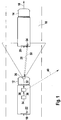
- FIG. 1 shows a control vehicle with an embodiment of the transmission device when reading a mark from a foreign vehicle. Shown is a roadway 10, on which two vehicles 12 and 14 drive one behind the other in a direction of travel 16. The control vehicle 12 drives behind the other vehicle 14. In the in FIG. 1 As shown, the control vehicle 12 is adapted to read markings from the preceding foreign vehicle 14. However, the present invention is not limited to that in FIG. 1 shown embodiment limited. Alternatively or in addition, the control vehicle 12 may also be configured to determine the markings of all vehicles within a certain perimeter.
- Both vehicles 12 and 14 have number plates 18 and 20 on their rear sides.
- both vehicles 12 and 14 are each equipped with an RFID transponder (Radio Frequency Identification) 22 and 24.
- RFID transponders 22 and 24 are disposed near the rear sides of the vehicles 12 and 14, respectively.
- the RFID transponders 22 and 24 may be attached to other mounting locations of the vehicles 12 and 14 as well.
- the control vehicle 12 has on its front side a sensor device 26 with which the license plate 20 and the RFID transponder 24 of the foreign vehicle 14 can be read.
- the sensor device 26 includes a camera with a connected image processing device.
- the image processing device evaluates a video signal provided by the camera with regard to the license plate shown on the license plate 20.
- the sensor device 26 has an interrogator (reader) for generating an electromagnetic field 28.
- the electromagnetic field 28 causes the RFID transponder 24 of the foreign vehicle 14 to emit its identification number as an electromagnetic signal 30.
- the interrogator of the sensor device 26 then receives the emitted from the RFID transponder 24 electromagnetic signal 30 with the identification number.
- the identification number is then output as marking information 32 together with the identification number of the license plate 20 of the foreign vehicle 14 determined by the image processing device.
- the control vehicle 12 is equipped with a position detection device 34, which determines a current position of the control vehicle 12 on the basis of a satellite signal. A determined by the position determining means 34 current position of the Control vehicle 12 is continuously output as position information 36 to a transmitting device 38.
- the position detection device 34 is also designed in a preferred embodiment to supply a navigation system of the control vehicle 12 with information about the current position of the control vehicle 12. This multifunctionality of the position detection device 34 is associated with cost savings for the driver of the control vehicle 12.
- the transmitting device 38 receives the output position information 36 together with the marking information 32 provided by the sensor device 26.
- the transmitting device 38 then sends a long-distance signal 40 to an evaluation station (not shown).
- the long-distance signal 40 contains information about the markings 20 and 24 of the foreign vehicle 14 and about the current position of the control vehicle 12.
- FIG. 2 shows the control vehicle 12 together with the preceding foreign vehicle 14.
- the control vehicle 12 is currently transmitting the long-distance signal 40 to an evaluation center 42.
- the evaluation center 42 is in the example off FIG. 2 assigned to a system for electronic toll collection. It determines the identity of the foreign vehicle 14 on the basis of the long-distance signal 40.
- the evaluation center 42 then compares the current position reported by the control vehicle 12 with the aid of the long-distance signal 40 with the positions which the foreign vehicle 14 itself has to determine a driver to pay for the foreign vehicle 14 Toll to the evaluation center 42 sends.
- the evaluation center 42 determines that the control vehicle 12 recognizes the markings 20 and 24 of the foreign vehicle 14 at a position which deviates significantly from the current position reported by the foreign vehicle 14 itself, it issues a corresponding message to the toll operator.
- the toll operator now has the option to check the other vehicle 14 specifically for the correctness of the data reported by the other vehicle 14.
- the other vehicle 14 may still be possible sent data are made. If the foreign vehicle 14 is detected at at least two different locations within a certain time, the toll center can check whether a correct minimum distance or a correct minimum toll amount has been reported to the toll center for the distance between the two locations from the other vehicle 14.
- the sensor device 26 can also output a video signal to a display device of the control vehicle 12.
- a corresponding display device is, for example, a parking aid, a reversing aid and / or a tote-angle display aid.
- the sensor device 26 may provide a video signal to a driver assistance system and / or to a lane departure warning device.
- the sensor device 26 may also be designed to determine a distance between the control vehicle 12 and the foreign vehicle 14 and / or a speed of the foreign vehicle 14 and a corresponding distance and / or speed signal to an on-board control device, for example to a driver assistance system, to an emergency brake system and / or to an airbag deployment system.
- Such a distance and / or speed signal can also be output by the sensor device 26 to an on-board warning device, for example to a collision warning.
- the sensor device 26 can perform other functions that improve the safety of the occupants and the ride comfort for the driver of the control vehicle 12 equipped therewith. Due to the multifunctionality of the sensor device 26 of the transmission device, the number of attached to the control vehicle 12 sensors can be reduced. This eliminates the cost of the saved sensors. In addition, the available space for other components of the control vehicle 12 space is increased.
Description
Die vorliegende Erfindung betrifft eine Übermittlungsvorrichtung und ein Verfahren zum Übermitteln einer aktuellen Position eines Fahrzeugs an eine Auswertezentrale gemäß dem Oberbegriff des unabhängigen Anspruchs 1 bzw. 7, wie aus der
Die
Häufig versuchen Fahrer von mautpflichtigen Fahrzeugen das zum Ermitteln der Maut an ihrem Fahrzeug angebrachte Gerät zu manipulieren. Beispielsweise entfernen manche Fahrer die OBU-Einheit (On-Bord-Unit) von ihrem Fahrzeug, um zu verhindern, dass diese beim Befahren einer bemauteten Straße eine entsprechende Information an das System zur elektronischen Mauterhebung aussendet. Man bezeichnet Fahrzeuge mit derartigen Manipulationen häufig als Mautpreller.Frequently, drivers of toll vehicles attempt to manipulate the device attached to determine the toll on their vehicle. For example, some drivers remove the on-board unit (OBU) from their vehicle to prevent it from transmitting appropriate information to the electronic toll collection system when driving on a tolled road. Vehicles with such manipulations are often referred to as toll bollards.
Herkömmlicherweise enthalten Systeme zur elektronischen Mauterhebung deshalb ortsfeste Kontrollvorrichtungen zum Erkennen und zum Identifizieren von Mautprellern. Die ortsfesten Kontrollvorrichtungen sind in der Regel dazu ausgebildet, das Fehlen einer OBU-Einheit oder die nicht korrekte Funktionsweise einer OBU-Einheit an einem mautpflichtigen Fahrzeug in ihrer näheren Umgebung zu erkennen. In der Regel sind die ortsfesten Kontrollvorrichtungen als Mautbrücken ausgebildet.Conventionally, electronic toll collection systems therefore include fixed control devices for recognizing and identifying toll bouncers. The stationary control devices are usually designed to detect the absence of an OBU unit or the incorrect functioning of an OBU unit on a toll vehicle in its immediate vicinity. In general, the stationary control devices are designed as toll bridges.
Der Nachteil dieser Mautbrücken liegt in den hohen Kosten, welche beim Errichten einer Mautbrücke anfallen. Zusätzlich sind die Mautbrücken eines herkömmlichen Systems zur elektronischen Mauterhebung nur dazu ausgelegt, Fahrzeuge in ihrer unmittelbaren Umgebung hinsichtlich einer vorhandenen und richtig arbeitenden OBU-Einheit zu überprüfen.The disadvantage of these toll bridges lies in the high costs that are incurred when building a toll bridge. In addition, the toll bridges of a conventional electronic toll collection system are designed only to check vehicles in their immediate vicinity for an existing and properly functioning OBU unit.
Um einen hohen Prozentsatz der Flächen aller bemauteten Straßen hinsichtlich eines Befahrens durch einen Mautpreller zu überprüfen muss deshalb eine relativ hohe Anzahl von Mautbrücken aufgebaut werden. Dies ist vor allem bei einer flächendeckenden Bemautung auf allen Straßen innerhalb eines Gebiets mit sehr hohen Kosten verbunden.In order to check a high percentage of the surfaces of all tolled roads with regard to driving through a toll bumper, a relatively high number of toll bridges must therefore be set up. This is particularly associated with a nationwide toll on all roads within an area with very high costs.
Wünschenswert wäre es deshalb, eine kostengünstige Möglichkeit zum Erkennen und Identifizieren von Mautprellern zu haben, welche eine hohe Abdeckungsrate der Flächen aller bemauteten Straßen ermöglicht.It would therefore be desirable to have a cost effective way of recognizing and identifying toll bouncers, which allows a high coverage rate of the areas of all tolled roads.
Die Erfindung schafft eine Übermittlungsvorrichtung mit den Merkmalen des Anspruchs 1 und ein Verfahren mit den Merkmalen des Anspruchs 7.The invention provides a transmission device having the features of
Der Erfindung liegt die Erkenntnis zugrunde, dass Mautpreller ohne den Einsatz stationärer Kontrollvorrichtungen erkennbar und identifizierbar sind, indem eine Anzahl von Fahrzeugen mit einer erfindungsgemäßen Übermittlungsvorrichtung ausgestattet werden, welche dazu ausgelegt ist, eine optische und elektromagnetische Markierung von einem Fremdfahrzeug zusammen mit der eigenen Fahrzeugposition an eine Auswertezentrale zu übermitteln. Die Auswertezentrale erkennt dann die Identität des Fremdfahrzeugs anhand der von dem Fahrzeug übermittelten Information und fragt ab, welche Daten von dem erkannten Fremdfahrzeug innerhalb einer vorgegebenen Zeitdauer empfangen werden. Anschließend ermittelt die Auswertezentrale aus den Daten die von dem Fremdfahrzeug selbst angegebene aktuelle eigene Fahrzeugposition. Die von dem Fremdfahrzeug selbst angegebene eigene Fahrzeugposition wird mit der gemeldeten Position des Fahrzeugs mit der Übermittlungsvorrichtung verglichen. Stellt die Auswertezentrale dabei einen Widerspruch zwischen der von dem Fahrzeug mit der Übermittlungsvorrichtung gesendeten Position und dem vom Fremdfahrzeug selbst übermittelten aktuellen eigenen Fahrzeugposition fest, so benachrichtigt sie den Mautbetreiber. Das Fremdfahrzeug kann anschließend durch den Mautbetreiber gezielt hinsichtlich einer möglichen Manipulation der OBU-Einheit überprüft werden.The invention is based on the finding that toll bumpers are recognizable and identifiable without the use of stationary control devices by equipping a number of vehicles with a transmission device according to the invention which is designed to display an optical and electromagnetic marking from a foreign vehicle together with its own vehicle position to transmit an evaluation center. The evaluation center then recognizes the identity of the foreign vehicle based on the information transmitted by the vehicle and queries which data is received by the detected foreign vehicle within a predetermined period of time. Subsequently, the evaluation center determines from the data the current own vehicle position specified by the foreign vehicle itself. The own vehicle position indicated by the foreign vehicle itself is compared with the reported position of the vehicle with the transmission device. If the evaluation center determines a contradiction between the position transmitted by the vehicle with the transmission device and the current own vehicle position transmitted by the other vehicle, it notifies the toll operator. The other vehicle can then be checked by the toll operator in terms of a possible manipulation of the OBU unit.
Dabei kann die Positionsinformation eine Ortkoordinate, ein Straßenabschnitt oder eine geographische Zone sein. Gehört das fahrzeugeigene Positionserfassungsgerät beispielsweise zu einem Navigationssystem, so ist es einfacher, einen Straßenabschnitt als Positionsinformation bereitzustellen. Die Positionsinformation kann damit auch nur eine ungefähre Information über die aktuelle Position des Kontrollfahrzeugs sein.The position information may be a local coordinate, a road segment or a geographical zone. For example, when the on-vehicle position detecting apparatus belongs to a navigation system, it is easier to provide a road section as position information. The position information can thus only be an approximate information about the current position of the control vehicle.
Dabei weist eine bevorzugte Ausführungsform der Erfindung den Vorteil auf, dass ein mit der erfindungsgemäßen Übermittlungsvorrichtung ausgestattetes Fahrzeug als solches nicht erkennbar ist. Eine Begegnung mit einem solchen Fahrzeug kann von einem Mautpreller deshalb nicht vermieden werden. Eine durch die Erfindung ermöglichte Überprüfung eines mautpflichtigen Fahrzeugs ist daher zeit- und ortsunabhängig. Dies stellt einen Vorteil gegenüber Mautbrücken dar, deren Lage einem Fahrer schnell bekannt ist und die mit diesem Wissen leicht umfahrbar sind. Als Alternative dazu kann das mit der Übermittlungsvorrichtung ausgestattete Fahrzeug auch durch Markierungen, beispielsweise durch spezielle Aufkleber, als solches anderen Fahrzeugen angezeigt werden, sofern dies aus datenschutzrechtlichen Gründen erforderlich ist.In this case, a preferred embodiment of the invention has the advantage that a vehicle equipped with the transmission device according to the invention is not recognizable as such. An encounter with such a vehicle can therefore not be avoided by a toll-bumper. An enabled by the invention review of a toll vehicle is therefore time and place independent. This is an advantage over toll bridges whose location is quickly known to a driver and which are easily navigable with this knowledge. Alternatively, the vehicle equipped with the transmission device may also be indicated as such to other vehicles by markings such as special stickers, if necessary for reasons of data protection law.
Da eine nicht erfindungsgemäße Übermittlungsvorrichtung in ihrer einfachsten Ausführungsform nur über eine Sensor- und/oder Auswerteeinrichtung zum Ablesen einer elektromagnetischen Markierung und über eine Sendeeinrichtung zum Aussenden eines Langstreckensignals verfügen muss, lässt sie sich kostengünstig herstellen. Die aufwändigen Auswertevorrichtungen zum Identifizieren des Fremdfahrzeugs und zum Ermitteln, ob es sich bei dem Fremdfahrzeug um einen Mautpreller handelt, sind in diesem Fall nur an der Auswertezentrale angeordnet. Damit lässt sich eine hohe Anzahl von Fahrzeugen auf kostengünstige Weise mit der Übermittlungsvorrichtung ausrüsten.Since a transmission device not according to the invention in its simplest embodiment only has to have a sensor and / or evaluation device for reading an electromagnetic marking and a transmitting device for transmitting a long-distance signal, it can be produced inexpensively. The complex evaluation devices for identifying the foreign vehicle and for determining whether the foreign vehicle is a toll-bumper are arranged in this case only at the evaluation center. This makes it possible to equip a high number of vehicles in a cost effective manner with the transmission device.
Als weitere Vereinfachung kann die Sensor- und/oder Auswerteeinrichtung nur eine Auswerteeinrichtung sein. Diese Auswerteeinrichtung ist dann dazu ausgelegt, von einer fahrzeugeigenen Sensoreinrichtung bereitgestellte Daten, beispielsweise ein von einer fahrzeugeigenen Kameraeinrichtung aufgenommenes Videosignal, hinsichtlich der Markierung des Fremdfahrzeugs auszuwerten. Beispielsweise erhält die Auswerteeinrichtung die Umgebungsdaten von einer Fahrspurhalte-Warneinrichtung (Lane Departure Warning System) und wertet diese dann entsprechend aus.As a further simplification, the sensor and / or evaluation device can only be an evaluation device. This evaluation device is then designed to evaluate data provided by a vehicle-specific sensor device, for example a video signal recorded by an on-board camera device, with regard to the marking of the foreign vehicle. For example, the evaluation device receives the environmental data from a lane departure warning system (Lane Departure Warning System) and then evaluates them accordingly.
Die Ausstattung eines Fahrzeugs mit der erfindungsgemäßen Übermittlungsvorrichtung ist deshalb bei hoher Straßennetzabdeckung günstiger als die üblichen stationären Mautbrücken. Der gewünschte Abdeckungsgrad lässt sich durch die Anzahl der mit der Übermittlungsvorrichtung ausgestatteten Fahrzeuge und deren Region anpassen.The equipment of a vehicle with the transmission device according to the invention is therefore cheaper with high road network coverage than the usual stationary toll bridges. The desired degree of coverage can be adjusted by the number of vehicles equipped with the transmission device and their region.
Zur Mautprellererkennung wird eine beliebige Anzahl von Fahrzeugen mit der erfindungsgemäßen Übermittlungsvorrichtung ausgestattet, die ein Ablesen der optischen und elektromagnetischen Markierung und eine Kommunikation mit dem Rechenzentrum des Mautbetreibers ermöglicht. Die Ausrüstung des Fahrzeugs mit der Übermittlungsvorrichtung kann als Erweiterung zu einer schon am Fahrzeug vorhandenen OBU-Einheit (On-Bord-Unit) ausgeführt werden. Dies reduziert die Kosten für eine derartige Übermittlungsvorrichtung zusätzlich.For Mautprellererkennung any number of vehicles is equipped with the transmission device according to the invention, which allows reading the optical and electromagnetic mark and communication with the data center of the toll operator. The equipment of the vehicle with the transmission device can be executed as an extension to an existing on-vehicle OBU unit (on-board unit). This additionally reduces the cost of such a transmission device.
In einer bevorzugten Ausführungsform der Übermittlungsvorrichtung weist die Sensor- und/oder Auswerteeinrichtung eine Laser- und Detektionseinrichtung zum visuellen Erfassen zumindest einer Teiloberfläche des Fremdfahrzeugs auf. Eine derartige Sensoreinrichtung lässt sich auf kostengünstige Weise herstellen und eignet sich gut zum Ablesen einer optischen Markierung eines Fremdfahrzeugs.In a preferred embodiment of the transmission device, the sensor and / or evaluation device has a laser and detection device for the visual detection of at least one partial surface of the foreign vehicle. Such a sensor device can be produced in a cost-effective manner and is well suited for reading an optical marking of a foreign vehicle.
Die optische Markierung des Fremdfahrzeugs ist ein Nummernschild. Da Fahrzeuge herkömmlicher Weise mit einem Nummernschild ausgestattet sein müssen, ist somit schon eine für die Übermittlungsvorrichtung erkennbare Markierung an jedem Fremdfahrzeug vorhanden. Die Übermittlungsvorrichtung kann in diesem Fall als ANPR-System (Automatic Number Plate Recognition) oder als einfache Kamera mit einer Bildverarbeitungseinrichtung ausgebildet sein. Die beschriebene Ausführungsform der Übermittlungsvorrichtung lässt sich damit kostengünstig realisieren.The optical marking of the other vehicle is a license plate. Since vehicles must be conventionally equipped with a license plate, thus already recognizable for the transmission device marking on each other vehicle is present. In this case, the transmission device can be designed as an ANPR (Automatic Number Plate Recognition) system or as a simple camera with an image processing device. The described embodiment of the transmission device can thus be implemented inexpensively.
In einer Weiterbildung ist die Sensor- und/oder Auswerteeinrichtung zusätzlich dazu ausgelegt, einen Abstand zwischen dem Fahrzeug und dem Fremdfahrzeug und/oder eine Geschwindigkeit des Fremdfahrzeugs zu ermitteln und ein entsprechendes Abstands-und/oder Geschwindigkeitssignal an ein fahrzeugeigenes Warn- und/oder Steuergerät, beispielsweise an eine Kollisions-Warnung, an ein Fahrerassistenzsystem, an ein Notbremssystem und/oder an ein Airbagauslösesystem, bereitzustellen. Durch diese Multifunktionalität der Sensor- und/oder Auswerteeinrichtung der Übermittlungsvorrichtung können weitere Sensoren am Fahrzeug eingespart werden.In one development, the sensor and / or evaluation device is additionally designed to determine a distance between the vehicle and the foreign vehicle and / or a speed of the foreign vehicle and a corresponding distance and / or speed signal to an on-board warning and / or control device To provide, for example, to a collision warning to a driver assistance system, to an emergency braking system and / or to an airbag deployment system. By this multi-functionality of the sensor and / or evaluation of the transmission device further sensors can be saved on the vehicle.
In einer bevorzugten Weiterbildung der Übermittlungsvorrichtung ist die Sensor- und/oder Auswerteeinrichtung zusätzlich dazu ausgelegt, eine Umgebung des Fahrzeugs aufzunehmen und als Videosignal an eine fahrzeugeigene Anzeigeeinrichtung, beispielsweise an eine Einparkhilfe, eine Rückfahrhilfe und/oder eine Tote-Winkel-Anzeigehilfe, bereitzustellen. Das Ausstatten eines Fahrzeugs mit der Übermittlungsvorrichtung führt damit zu einer Verbesserung des Fahrkomforts für den Fahrer des Fahrzeugs.In a preferred development of the transmission device, the sensor and / or evaluation device is additionally designed to record an environment of the vehicle and to provide it as a video signal to an on-board display device, for example to a parking aid, a reversing aid and / or a blind spot display aid. The provision of a vehicle with the transmission device thus leads to an improvement of the ride comfort for the driver of the vehicle.
Als Alternative oder als Ergänzung dazu kann die Sensor- und/oder Auswerteeinrichtung zusätzlich dazu ausgelegt sein, eine Umgebung des Fahrzeugs aufzunehmen und als Videosignal an eine fahrzeugeigene Auswerteeinrichtung zum Ermitteln einer hinsichtlich der Umgebung vorteilhaften Reaktion des Fahrzeugs, beispielsweise an ein Fahrerassistenzsystem und/oder an eine Fahrspur-Einhaltevorrichtung (Lane Departure Warnung), bereitzustellen. Durch die Multifunktionalität der Sensor- und/oder Auswerteeinrichtung kann zusätzlich Bauraum am Fahrzeug eingespart werden.As an alternative or as a supplement to this, the sensor and / or evaluation device can additionally be designed to record an environment of the vehicle and as a video signal to an on-board evaluation device for determining a reaction of the vehicle which is advantageous with regard to the environment, for example to a driver assistance system and / or to provide a lane departure warning device (lane departure warning). Due to the multi-functionality of the sensor and / or evaluation can be additionally saved space on the vehicle.
Erfindungsgemäß weist die Sensor- und/oder Auswerteeinrichtung ein Lesegerät zum Erzeugen eines elektromagnetischen Wechselfelds zum Anregen eines RFID-Transponders (Radio Frequency Identification) und zum Empfangen einer von dem angeregten RFID-Transponder ausgesendeten Seriennummer auf. RFID wird zurzeit in einigen Ländern zusätzlich zu den klassischen Kennzeichen eines Fahrzeugs als
Fahrzeugidentifikationsmittel erprobt. Zudem wird RFID zur Kennzeichnung von Fahrzeugbauteilen bei der Herstellung der Fahrzeugbauteile eingesetzt. Damit steht die zur Realisierung dieser Ausführungsform verwendete Technologie bereits zur Verfügung. Ein weiterer Vorteil liegt darin, dass sich ein Lesegerät zum Ablesen eines RFID-Transponders und der RFID-Transponder selbst kostengünstig herstellen lassen.According to the invention, the sensor and / or evaluation device has a reading device for generating an alternating electromagnetic field for exciting an RFID transponder (Radio Frequency Identification) and for receiving a serial number transmitted by the excited RFID transponder. RFID is currently used in addition to the classic features of a vehicle in some countries
Vehicle identification tested. In addition, RFID is used to identify vehicle components in the manufacture of vehicle components. Thus, the technology used to implement this embodiment is already available. Another advantage is that a reader for reading an RFID transponder and the RFID transponder itself can be produced inexpensively.
In einer Weiterbildung weist die Sensor- und/oder Auswerteeinrichtung eine Auswerteeinrichtung zum Ermitteln einer Identität des Fremdfahrzeugs anhand der optischen und/oder elektromagnetischen Markierung auf. Damit kann bereits am Fahrzeug selbst die Identität des Fremdfahrzeugs ermittelt werden.In a development, the sensor and / or evaluation device has an evaluation device for determining an identity of the foreign vehicle on the basis of the optical and / or electromagnetic marking. Thus, the identity of the foreign vehicle can already be determined on the vehicle itself.
Gemäß der Erfindung ist die Auswertezentrale eine Mautzentrale. Vorzugsweise identifiziert die Mautzentrale das Fremdfahrzeug anhand der gemeldeten optischen und/oder elektromagnetischen Markierung und vergleicht die gemeldete Position des Fremdfahrzeugs mit den zur Mauterhebung gemeldeten Positionen des Fremdfahrzeugs. Auf diese Weise kann die Mautzentrale schnell ein Fahrzeug, dessen OBU-Einheit zum Ermitteln der zu zahlenden Maut manipuliert oder vom Fahrzeug entfernt ist, erkennen.According to the invention, the evaluation center is a toll center. The toll center preferably identifies the foreign vehicle on the basis of the reported optical and / or electromagnetic marker and compares the reported position of the foreign vehicle with the positions of the foreign vehicle reported for toll collection. In this way, the toll center can quickly recognize a vehicle whose OBU unit is being manipulated to determine the toll to be paid or removed from the vehicle.
Die in den oberen Absätzen beschriebenen Vorteile der erfindungsgemäßen Übermittlungsvorrichtung sind auch durch ein entsprechendes Verfahren zum Übermitteln einer aktuellen Position eines ersten Fahrzeugs an eine Auswertezentrale gewährleistet.The ones described in the upper paragraphs Advantages of the transmission device according to the invention are also ensured by a corresponding method for transmitting a current position of a first vehicle to an evaluation center.
In einer bevorzugten Ausführungsform des Verfahrens wird nach einem Empfang des Langstreckensignals anhand der Markierungsinformation eine Identität des ersten Fahrzeugs ermittelt, und die Positionsinformation wird mit einer von dem ersten Fahrzeug selbst an die Auswertezentrale gesendeten Ortinformation und/oder Mindestmaut verglichen. Dabei können auch die Langstreckensignale mehrerer Fahrzeuge herangezogen werden. Wird das erste Fahrzeug beispielsweise innerhalb einer vorgegebenen Zeitdauer an zwei Orten gemeldet, so überprüft die Auswertezentrale, ob die von dem ersten Fahrzeug zurückgelegte Strecke zwischen den beiden Orten nicht größer ist als eine von dem ersten Fahrzeug selbst gemeldete zurückgelegte Wegstrecke. Ebenso kann die Auswertezentrale für die Strecke zwischen den beiden Orten eine Mindestmaut bestimmen und überprüfen, ob die von dem ersten Fahrzeug selbst gemeldete zu bezahlende Maut mindestens diesem Betrag entspricht.In a preferred embodiment of the method, an identity of the first vehicle is determined after receipt of the long-distance signal on the basis of the marking information, and the position information is compared with a location information and / or minimum toll transmitted by the first vehicle itself to the evaluation center. In this case, the long-distance signals of several vehicles can be used. If the first vehicle is reported at two locations, for example, within a predetermined period of time, the evaluation center checks whether the distance traveled by the first vehicle between the two locations is not greater than a distance traveled by the first vehicle itself. Similarly, the evaluation center may determine a minimum toll for the route between the two locations and check whether the toll to be paid reported by the first vehicle itself is at least equal to that amount.
Weitere Merkmale und Vorteile der vorliegenden Erfindung werden nachfolgend anhand der Figuren erläutert. Es zeigen:
chen. Dabei können auch die Langstreckensignale mehrerer Fahrzeuge herangezogen werden. Wird das erste Fahrzeug beispielsweise innerhalb einer vorgegebenen Zeitdauer an zwei Orten gemeldet, so überprüft die Auswertezentrale, ob die von dem ersten Fahrzeug zurückgelegte Strecke zwischen den beiden Orten nicht größer ist als eine von dem ersten Fahrzeug selbst gemeldete zurückgelegte Wegstrecke. Ebenso kann die Auswertezentrale für die Strecke zwischen den beiden Orten eine Mindestmaut bestimmen und überprüfen, ob die von dem ersten Fahrzeug selbst gemeldete zu bezahlende Maut mindestens diesem Betrag entspricht.Further features and advantages of the present invention will be explained below with reference to the figures. Show it:
chen. In this case, the long-distance signals of several vehicles can be used. If the first vehicle is reported at two locations, for example, within a predetermined period of time, then the evaluation center checks whether the distance covered by the first vehicle between the two locations is not greater than a distance traveled by the first vehicle itself. Similarly, the evaluation center may determine a minimum toll for the route between the two locations and check whether the toll to be paid reported by the first vehicle itself is at least equal to that amount.
Weitere Merkmale und Vorteile der vorliegenden Erfindung werden nachfolgend anhand der Figuren erläutert. Es zeigen:
-
Figur 1 -
Figur 2 dasKontrollfahrzeug der Figur 1 beim Senden an eine Auswertezentrale.
-
FIG. 1 a control vehicle having an embodiment of the transmission device when reading a marker from a foreign vehicle; and -
FIG. 2 the control vehicle ofFIG. 1 when sending to an evaluation center.
Beide Fahrzeuge 12 und 14 weisen an ihren Heckseiten Nummernschilder 18 und 20 auf. Zusätzlich sind beide Fahrzeuge 12 und 14 mit je einem RFID-Transponder (Radio Frequency Identification) 22 und 24 ausgestattet. In dem Beispiel aus
Das Kontrollfahrzeug 12 weist an seiner Frontseite eine Sensoreinrichtung 26 auf, mit welcher das Nummernschild 20 und der RFID-Transponder 24 des Fremdfahrzeugs 14 abgelesen werden können. Zum Ablesen des Nummernschildes 20 des Fremdfahrzeugs 14 umfasst die Sensoreinrichtung 26 eine Kamera mit einer angeschlossenen Bildverarbeitungseinrichtung. Die Bildverarbeitungseinrichtung wertet ein von der Kamera bereitgestelltes Videosignal hinsichtlich des auf dem Nummernschild 20 abgebildeten Kennzeichens aus.The
Des Weiteren weist die Sensoreinrichtung 26 ein Abfragegerät (Reader) zum Erzeugen eines elektromagnetischen Felds 28 auf Durch das elektromagnetische Feld 28 wird der RFID-Transponder 24 des Fremdfahrzeugs 14 dazu angelegt, seine Identifikationsnummer als elektromagnetisches Signal 30 auszusenden. Das Abfragegerät der Sensoreinrichtung 26 empfängt dann das von dem RFID-Transponder 24 ausgesendete elektromagnetische Signal 30 mit der Identifikationsnummer. Die Identifikationsnummer wird anschließend zusammen mit dem von der Bildverarbeitungseinrichtung ermittelten Kennzeichen des Nummernschilds 20 des Fremdfahrzeugs 14 als Markierungsinformation 32 ausgegeben.Furthermore, the
Es wird hier darauf hingewiesen, dass das Ablesen der am Fremdfahrzeug 14 angebrachten Markierungen 20 und 24 durch die Sensoreinrichtung 26 des Kontrollfahrzeugs 12 erfolgt, ohne dass der Fahrer des Fremdfahrzeugs 14 eine Möglichkeit hat, dies zu verhindern oder in den Ableseprozess aktiv einzugreifen. Nummernschilder 18 und 20 und RFID-Transponder 22 und 24 sind herkömmlicher Weise so ausgelegt, dass Manipulationen an ihnen kaum möglich sind.It is pointed out here that the reading of the
Das Kontrollfahrzeug 12 ist mit einer Positionserfassungseinrichtung 34 ausgestattet, welche eine aktuelle Position des Kontrollfahrzeugs 12 anhand eines Satellitensignals ermittelt. Eine von der Positionsbestimmungseinrichtung 34 ermittelte aktuelle Position des Kontrollfahrzeugs 12 wird fortlaufend als Positionsinformation 36 an eine Sendeeinrichtung 38 ausgegeben.The
Die Positionserfassungseinrichtung 34 ist in einer bevorzugten Ausführungsform auch dazu ausgelegt, ein Navigationssystem des Kontrollfahrzeugs 12 mit einer Information über die aktuelle Position des Kontrollfahrzeugs 12 zu versorgen. Diese Multifunktionalität der Positionserfassungseinrichtung 34 ist für den Fahrer des Kontrollfahrzeugs 12 mit Kosteneinsparungen verbunden.The
Die Sendeeinrichtung 38 empfängt die ausgegebene Positionsinformation 36 zusammen mit der von der Sensoreinrichtung 26 bereitgestellten Markierungsinformation 32. Anschließend sendet die Sendeeinrichtung 38 ein Langstreckensignal 40 an eine nicht skizzierte Auswertezentrale. Das Langstreckensignal 40 enthält dabei Informationen über die Markierungen 20 und 24 des Fremdfahrzeugs 14 und über die aktuelle Position des Kontrollfahrzeugs 12.The transmitting
Sollte das Fremdfahrzeug 14 beispielsweise aus Datenschutzgründen auf das Senden seiner Positionsinformation an eine Mautzentrale verzichten (thick-client-Konzept) und lediglich den OBU-internen ermittelten Mautbetrag oder die ermittelte zurückgelegte Distanz an die Mautzentrale übertragen, so kann dennoch eine Kontrolle der vom Fremdfahrzeug 14 gesendeten Daten vorgenommen werden. Wird das Fremdfahrzeug 14 an mindestens zwei unterschiedlichen Orten innerhalb einer bestimmten Zeit erfasst, so kann die Mautzentrale prüfen, ob für die Distanz zwischen den beiden Orten vom Fremdfahrzeug 14 eine korrekte Mindestdistanz oder ein korrekter Mindestmautbetrag an die Mautzentrale gemeldet wurde.Should the
In einer Weiterbildung kann die Sensoreinrichtung 26 auch ein Videosignal an ein Anzeigegerät des Kontrollfahrzeugs 12 ausgeben. Ein entsprechendes Anzeigegerät ist beispielsweise eine Einparkhilfe, eine Rückfahrhilfe und/oder eine Tote-Winkel-Anzeigehilfe. Ebenso kann die Sensoreinrichtung 26 ein Videosignal an ein Fahrerassistenzsystem und/oder an eine Fahrspur-Einhaltevorrichtung (Lane Departure Warnung) bereitzustellen. Als Alternative oder als Ergänzung dazu kann die Sensoreinrichtung 26 auch dazu ausgelegt sein, einen Abstand zwischen dem Kontrollfahrzeug 12 und dem Fremdfahrzeug 14 und/oder eine Geschwindigkeit des Fremdfahrzeugs 14 zu ermitteln und ein entsprechendes Abstands- und/oder Geschwindigkeitssignal an ein fahrzeugeigenes Steuergerät, beispielsweise an ein Fahrerassistenzsystem, an ein Notbremssystem und/oder an ein Airbagauslösesystem bereitstellen. Ein derartiges Abstands- und/oder Geschwindigkeitssignal kann von der Sensoreinrichtung 26 auch an eine fahrzeugeigene Warnvorrichtung, beispielsweise an eine Kollisions-Warnung, ausgegeben werden. Damit kann die Sensoreinrichtung 26 weitere Funktionen, welche die Sicherheit der Insassen und den Fahrkomfort für den Fahrer des damit ausgestatteten Kontrollfahrzeugs 12 verbessern, ausführen. Durch die Multifunktionalität der Sensoreinrichtung 26 der Übermittlungsvorrichtung kann die Anzahl der am Kontrollfahrzeug 12 angebrachten Sensoren reduziert werden. Auf diese Weise entfallen die Kosten für die eingesparten Sensoren. Zusätzlich wird so der für andere Komponenten des Kontrollfahrzeugs 12 zur Verfügung stehende Bauraum erhöht.In a development, the
Claims (8)
- Transmission apparatus for a vehicle (12) for transmitting a present position of another vehicle (14) to an evaluation centre (42) having- a sensor and/or an evaluation device (26) which is configured to read an optical and electromagnetic marking (20, 24) of the other vehicle (14) and to make available marking information (32) corresponding to the read optical and electromagnetic marking (20, 24); and- a transmitter device (38) which is configured to receive position information (36) which is made available by a vehicle-mounted position sensing device (34) and relates to a current position of the vehicle (12) and to receive the marking information (32) which is made available and to emit a long-distance signal (40) with the position information (36) which is made available and the marking information (32) which is made available, to the evaluation centre (42), characterized in that- the sensor and/or evaluation device (26) has a camera and image processing device for visually capturing at least part of the surface of the other vehicle (14) and a reading device for generating an electromagnetic alternating field for exciting an RFID transponder (24) of the other vehicle (14) as the electronic marking (24) and for receiving a serial number, emitted by the excited RFID transponder (24), as the marking information (32) which corresponds to the read electromagnetic marking (24), wherein the optical marking (20) of the other vehicle (14) is a number plate (20) and the serial number is output together with the registration number, obtained by the image processing device, of the number plate (20) of the other vehicle (14) as the marking information (32);
and- the evaluation centre (42) is a toll centre. - Transmission apparatus according to Claim 1, wherein the sensor and/or evaluation device (26) is configured additionally to read an optical marking (20) of the other vehicle (14) and to make available marking information (32) which corresponds to the read optical marking (20), and has a laser and detection device for visually capturing at least part of the surface of the other vehicle (14).
- Transmission apparatus according to Claim 1 or 2, wherein the sensor and/or evaluation device (26) is additionally configured to determine a distance between the vehicle (12) and the other vehicle (14) and/or a speed of the other vehicle (14) and to make available a corresponding distance and/or speed signal to a vehicle-mounted warning and/or control device, for example to a collision warning system, to a driver assistance system, to an emergency brake system and/or to an airbag triggering system.
- Transmission apparatus according to one of Claims 1 to 3, wherein the sensor and/or evaluation device (26) is additionally configured to record the surroundings of the vehicle (12) and make them available as a video signal to a vehicle-mounted display device, for example to a parking aid, a reversing aid and/or a blind spot display aid.
- Transmission apparatus according to one of Claims 1 to 3, wherein the sensor and/or evaluation device (26) is additionally configured to record the surroundings of the vehicle (12) and to make them available as a video signal to a vehicle-mounted evaluation device for determining a reaction of the vehicle (12), which is advantageous in terms of the surroundings, for example to a driver assistance system and/or to a lane keeping device (lane departure warning).
- Transmission apparatus according to Claim 1, wherein the sensor and/or evaluation device (26) has an evaluation device for determining an identity of the other vehicle (14) on the basis of the electromagnetic marking (24).
- Method for transmitting a current position of a first vehicle (14) to an evaluation centre (42), wherein the first vehicle (14) has an optical and electromagnetic marking (20, 24), comprising the steps:- reading the optical and electromagnetic marking (20, 24) of the first vehicle (14) by means of a sensor and/or evaluation device (26) of a second vehicle (12);- making available marking information (32), corresponding to the read optical and electromagnetic marking (20, 24), to a transmitter device (38) of the second vehicle (12);- making available position information (36) relating to a current position of the second vehicle (12) to the transmitter device (38); and- transmitting a long-distance signal (40) with the marking information (32) which is made available and the position information (36) which is made available, to the evaluation centre (42) by means of the transmitter device (38) of the second vehicle (12); characterized in that- the sensor and/or evaluation device (26) visually captures, by means of a camera and image processing device, at least part of the surface of the other vehicle (14) and excites, by means of a reading device for generating an electromagnetic alternating field, an RFID transponder (24) of the other vehicle (14) as the electronic marking (24), and receives a serial number, emitted by the excited RFID transponder (24), as the marking information (32) which corresponds to the read electromagnetic marking (24), wherein the optical marking (20) of the other vehicle (14) is a number plate (20) and the serial number is output together with the registration number, obtained by the image processing device, of the number plate (20) of the other vehicle (14) as the marking information (32); and- the evaluation centre (42) is a toll centre.
- Method according to Claim 7, wherein after a reception of the long-distance signal (40) an identity of the first vehicle is determined on the basis of the marking information (32), and the position information (36) is compared with location information and/or a minimum toll which is transmitted by the first vehicle itself to the evaluation centre (42).
Applications Claiming Priority (2)
| Application Number | Priority Date | Filing Date | Title |
|---|---|---|---|
| DE102007035738A DE102007035738A1 (en) | 2007-07-30 | 2007-07-30 | Transmission device and method for transmitting a current position of a vehicle to an evaluation center |
| PCT/EP2008/058657 WO2009015987A2 (en) | 2007-07-30 | 2008-07-04 | Transmission apparatus and method for transmitting a present position of a vehicle to an evaluation centre |
Publications (3)
| Publication Number | Publication Date |
|---|---|
| EP2176837A2 EP2176837A2 (en) | 2010-04-21 |
| EP2176837B1 EP2176837B1 (en) | 2016-09-07 |
| EP2176837B2 true EP2176837B2 (en) | 2019-09-04 |
Family
ID=39874867
Family Applications (1)
| Application Number | Title | Priority Date | Filing Date |
|---|---|---|---|
| EP08785917.9A Active EP2176837B2 (en) | 2007-07-30 | 2008-07-04 | Transmission apparatus and method for transmitting a present position of a vehicle to an evaluation centre |
Country Status (3)
| Country | Link |
|---|---|
| EP (1) | EP2176837B2 (en) |
| DE (1) | DE102007035738A1 (en) |
| WO (1) | WO2009015987A2 (en) |
Families Citing this family (6)
| Publication number | Priority date | Publication date | Assignee | Title |
|---|---|---|---|---|
| DK2312536T3 (en) * | 2009-10-15 | 2013-10-14 | Kapsch Trafficcom Ag | Vehicle apparatus for a toll system |
| GB201105385D0 (en) * | 2011-03-30 | 2011-05-11 | Act Wireless Ltd | Vehicle usuage verification system |
| EP2690602A3 (en) * | 2012-07-23 | 2017-10-04 | Toll Collect GmbH | Toll control method, toll control devices and toll system with such toll control devices |
| US20150279122A1 (en) * | 2012-10-17 | 2015-10-01 | Toll Collect Gmbh | Method and devices for collecting a traffic-related toll fee |
| DE102016225845A1 (en) * | 2016-12-21 | 2018-06-21 | Robert Bosch Gmbh | Toll control device |
| CN113393588B (en) * | 2020-03-12 | 2022-08-16 | 深圳市世纪本原科技股份有限公司 | Remote ETC load intelligent system based on mobile WiFi router |
Citations (4)
| Publication number | Priority date | Publication date | Assignee | Title |
|---|---|---|---|---|
| WO2001011572A1 (en) † | 1999-08-04 | 2001-02-15 | Vodafone Ag | Control unit for verifying proper functioning of toll devices installed in vehicles |
| DE10104502A1 (en) † | 2001-01-31 | 2002-08-14 | Daimler Chrysler Ag | Control procedure for road toll collection |
| US20050285743A1 (en) † | 2004-06-21 | 2005-12-29 | Weber Tory S | Method and device for detecting illegal operation of vehicles |
| US20070085704A1 (en) † | 2005-10-17 | 2007-04-19 | Cleverdevices, Inc. | Parking violation recording system and method |
Family Cites Families (3)
| Publication number | Priority date | Publication date | Assignee | Title |
|---|---|---|---|---|
| ITTO20020827A1 (en) | 2002-09-20 | 2004-03-21 | Elsag Spa | SYSTEM FOR SURVEILLANCE AND / OR SECURITY CONTROL |
| JP4823904B2 (en) | 2005-03-31 | 2011-11-24 | パナソニック株式会社 | Data encryption apparatus and data encryption method |
| DE102005058033A1 (en) * | 2005-12-05 | 2007-06-06 | Siemens Ag | Vehicle usage authorization verification method, involves exchanging information about presence of authorization between two vehicles, and displaying presence of authorization with vehicle identification on output unit of other vehicle |
-
2007
- 2007-07-30 DE DE102007035738A patent/DE102007035738A1/en not_active Ceased
-
2008
- 2008-07-04 WO PCT/EP2008/058657 patent/WO2009015987A2/en active Application Filing
- 2008-07-04 EP EP08785917.9A patent/EP2176837B2/en active Active
Patent Citations (4)
| Publication number | Priority date | Publication date | Assignee | Title |
|---|---|---|---|---|
| WO2001011572A1 (en) † | 1999-08-04 | 2001-02-15 | Vodafone Ag | Control unit for verifying proper functioning of toll devices installed in vehicles |
| DE10104502A1 (en) † | 2001-01-31 | 2002-08-14 | Daimler Chrysler Ag | Control procedure for road toll collection |
| US20050285743A1 (en) † | 2004-06-21 | 2005-12-29 | Weber Tory S | Method and device for detecting illegal operation of vehicles |
| US20070085704A1 (en) † | 2005-10-17 | 2007-04-19 | Cleverdevices, Inc. | Parking violation recording system and method |
Non-Patent Citations (4)
| Title |
|---|
| http://www.standards.its.dot.gov, beigefügt als Anlage 5 † |
| https://de.wikipedia.org/wiki/RFID, beigefügt als Anlage 7 † |
| Publikation der Europäischen Kommission, beigefügt als Anlage 8 † |
| RFID- Handbuch, ISBN 978-3-446-440398-7, beigefügt als Anlage 6 † |
Also Published As
| Publication number | Publication date |
|---|---|
| DE102007035738A1 (en) | 2009-02-05 |
| WO2009015987A3 (en) | 2009-04-09 |
| WO2009015987A2 (en) | 2009-02-05 |
| EP2176837A2 (en) | 2010-04-21 |
| EP2176837B1 (en) | 2016-09-07 |
Similar Documents
| Publication | Publication Date | Title |
|---|---|---|
| EP2312536B1 (en) | Vehicle device for a street toll system | |
| DE60025130T2 (en) | System for preventing collisions between vehicles and pedestrians | |
| DE19618922C2 (en) | Device and method for measuring the vehicle distance for motor vehicles | |
| EP2620929B1 (en) | Method and apparatus for detecting an exceptional traffic situation | |
| EP2054869B1 (en) | Method and apparatus for driver assistance through the production of lane information for supporting or replacing lane information from a video-based lane information device | |
| DE102014208673A1 (en) | Method and traffic monitoring device for detecting a wrong-way drive of a motor vehicle | |
| DE102006028625A1 (en) | Vehicle e.g. passenger car, measuring method, involves carrying out information exchange between sensor and driver assistance system, where exchange contains transmission of measuring data and/or vehicle parameter from sensor to vehicle | |
| EP2176837B2 (en) | Transmission apparatus and method for transmitting a present position of a vehicle to an evaluation centre | |
| DE102008010119A1 (en) | Device for detecting an object and system for communication between vehicles | |
| EP1446678B1 (en) | Method and device for detecting and classifying moving vehicles | |
| DE102011018159A1 (en) | Device and method for driver assistance | |
| WO2006037445A1 (en) | Method and device for warning a driver or actively intervening in the dynamics of vehicle movement in case the vehicle risks leaving a lane | |
| WO2008043842A2 (en) | Vehicle and method for identifying vehicles located in the surroundings of the vehicle | |
| DE19829162A1 (en) | Application of electronic camera and image recognition device in car for detecting traffic signs | |
| EP2193513B1 (en) | Device and method for detecting vehicles and the approach angles thereof | |
| DE202014003224U1 (en) | Driver assistance system for warning a driver of a collision with another road user | |
| WO2018054523A1 (en) | Method for warning a driver of a motor vehicle, taking into consideration the current range of vision of the driver, computing device and detection vehicle | |
| DE102022003175A1 (en) | Collision warning system for vehicles | |
| EP1084486A2 (en) | Device for improving road safety | |
| EP1094298B1 (en) | Method and device for driving using navigation support | |
| AT520261B1 (en) | Collision protection for rail vehicles | |
| DE102007021580A1 (en) | Device for detecting a road sign relevant for a vehicle comprises a first detector module for detecting lanes in the driving direction of the vehicle, a second detector module for detecting the road signs and a processing module | |
| DE102008039606A1 (en) | Motor vehicle with a distance sensor and an image acquisition system | |
| DE102017214497B4 (en) | Method of operating a motor vehicle, maneuvering device for a motor vehicle and motor vehicle | |
| WO2009015989A1 (en) | Method for checking a position message of a vehicle emitted from a vehicle and transmission and receiving device for use in a vehicle |
Legal Events
| Date | Code | Title | Description |
|---|---|---|---|
| PUAI | Public reference made under article 153(3) epc to a published international application that has entered the european phase |
Free format text: ORIGINAL CODE: 0009012 |
|
| 17P | Request for examination filed |
Effective date: 20100301 |
|
| AK | Designated contracting states |
Kind code of ref document: A2 Designated state(s): AT BE BG CH CY CZ DE DK EE ES FI FR GB GR HR HU IE IS IT LI LT LU LV MC MT NL NO PL PT RO SE SI SK TR |
|
| AX | Request for extension of the european patent |
Extension state: AL BA MK RS |
|
| DAX | Request for extension of the european patent (deleted) | ||
| 17Q | First examination report despatched |
Effective date: 20151005 |
|
| GRAP | Despatch of communication of intention to grant a patent |
Free format text: ORIGINAL CODE: EPIDOSNIGR1 |
|
| RIC1 | Information provided on ipc code assigned before grant |
Ipc: G07C 5/00 20060101ALI20160428BHEP Ipc: G07B 15/06 20110101ALI20160428BHEP Ipc: G07B 15/00 20110101AFI20160428BHEP |
|
| INTG | Intention to grant announced |
Effective date: 20160517 |
|
| GRAS | Grant fee paid |
Free format text: ORIGINAL CODE: EPIDOSNIGR3 |
|
| GRAA | (expected) grant |
Free format text: ORIGINAL CODE: 0009210 |
|
| AK | Designated contracting states |
Kind code of ref document: B1 Designated state(s): AT BE BG CH CY CZ DE DK EE ES FI FR GB GR HR HU IE IS IT LI LT LU LV MC MT NL NO PL PT RO SE SI SK TR |
|
| REG | Reference to a national code |
Ref country code: GB Ref legal event code: FG4D Free format text: NOT ENGLISH |
|
| REG | Reference to a national code |
Ref country code: CH Ref legal event code: EP |
|
| REG | Reference to a national code |
Ref country code: IE Ref legal event code: FG4D Free format text: LANGUAGE OF EP DOCUMENT: GERMAN |
|
| REG | Reference to a national code |
Ref country code: AT Ref legal event code: REF Ref document number: 827461 Country of ref document: AT Kind code of ref document: T Effective date: 20161015 |
|
| REG | Reference to a national code |
Ref country code: DE Ref legal event code: R096 Ref document number: 502008014615 Country of ref document: DE |
|
| REG | Reference to a national code |
Ref country code: NL Ref legal event code: FP |
|
| REG | Reference to a national code |
Ref country code: LT Ref legal event code: MG4D |
|
| PG25 | Lapsed in a contracting state [announced via postgrant information from national office to epo] |
Ref country code: LT Free format text: LAPSE BECAUSE OF FAILURE TO SUBMIT A TRANSLATION OF THE DESCRIPTION OR TO PAY THE FEE WITHIN THE PRESCRIBED TIME-LIMIT Effective date: 20160907 Ref country code: NO Free format text: LAPSE BECAUSE OF FAILURE TO SUBMIT A TRANSLATION OF THE DESCRIPTION OR TO PAY THE FEE WITHIN THE PRESCRIBED TIME-LIMIT Effective date: 20161207 Ref country code: FI Free format text: LAPSE BECAUSE OF FAILURE TO SUBMIT A TRANSLATION OF THE DESCRIPTION OR TO PAY THE FEE WITHIN THE PRESCRIBED TIME-LIMIT Effective date: 20160907 Ref country code: HR Free format text: LAPSE BECAUSE OF FAILURE TO SUBMIT A TRANSLATION OF THE DESCRIPTION OR TO PAY THE FEE WITHIN THE PRESCRIBED TIME-LIMIT Effective date: 20160907 |
|
| PG25 | Lapsed in a contracting state [announced via postgrant information from national office to epo] |
Ref country code: GR Free format text: LAPSE BECAUSE OF FAILURE TO SUBMIT A TRANSLATION OF THE DESCRIPTION OR TO PAY THE FEE WITHIN THE PRESCRIBED TIME-LIMIT Effective date: 20161208 Ref country code: SE Free format text: LAPSE BECAUSE OF FAILURE TO SUBMIT A TRANSLATION OF THE DESCRIPTION OR TO PAY THE FEE WITHIN THE PRESCRIBED TIME-LIMIT Effective date: 20160907 Ref country code: LV Free format text: LAPSE BECAUSE OF FAILURE TO SUBMIT A TRANSLATION OF THE DESCRIPTION OR TO PAY THE FEE WITHIN THE PRESCRIBED TIME-LIMIT Effective date: 20160907 Ref country code: ES Free format text: LAPSE BECAUSE OF FAILURE TO SUBMIT A TRANSLATION OF THE DESCRIPTION OR TO PAY THE FEE WITHIN THE PRESCRIBED TIME-LIMIT Effective date: 20160907 |
|
| PG25 | Lapsed in a contracting state [announced via postgrant information from national office to epo] |
Ref country code: EE Free format text: LAPSE BECAUSE OF FAILURE TO SUBMIT A TRANSLATION OF THE DESCRIPTION OR TO PAY THE FEE WITHIN THE PRESCRIBED TIME-LIMIT Effective date: 20160907 Ref country code: RO Free format text: LAPSE BECAUSE OF FAILURE TO SUBMIT A TRANSLATION OF THE DESCRIPTION OR TO PAY THE FEE WITHIN THE PRESCRIBED TIME-LIMIT Effective date: 20160907 |
|
| PG25 | Lapsed in a contracting state [announced via postgrant information from national office to epo] |
Ref country code: IS Free format text: LAPSE BECAUSE OF FAILURE TO SUBMIT A TRANSLATION OF THE DESCRIPTION OR TO PAY THE FEE WITHIN THE PRESCRIBED TIME-LIMIT Effective date: 20170107 Ref country code: PT Free format text: LAPSE BECAUSE OF FAILURE TO SUBMIT A TRANSLATION OF THE DESCRIPTION OR TO PAY THE FEE WITHIN THE PRESCRIBED TIME-LIMIT Effective date: 20170109 Ref country code: PL Free format text: LAPSE BECAUSE OF FAILURE TO SUBMIT A TRANSLATION OF THE DESCRIPTION OR TO PAY THE FEE WITHIN THE PRESCRIBED TIME-LIMIT Effective date: 20160907 Ref country code: CZ Free format text: LAPSE BECAUSE OF FAILURE TO SUBMIT A TRANSLATION OF THE DESCRIPTION OR TO PAY THE FEE WITHIN THE PRESCRIBED TIME-LIMIT Effective date: 20160907 Ref country code: SK Free format text: LAPSE BECAUSE OF FAILURE TO SUBMIT A TRANSLATION OF THE DESCRIPTION OR TO PAY THE FEE WITHIN THE PRESCRIBED TIME-LIMIT Effective date: 20160907 Ref country code: BG Free format text: LAPSE BECAUSE OF FAILURE TO SUBMIT A TRANSLATION OF THE DESCRIPTION OR TO PAY THE FEE WITHIN THE PRESCRIBED TIME-LIMIT Effective date: 20161207 |
|
| REG | Reference to a national code |
Ref country code: DE Ref legal event code: R026 Ref document number: 502008014615 Country of ref document: DE |
|
| PLBI | Opposition filed |
Free format text: ORIGINAL CODE: 0009260 |
|
| PLAX | Notice of opposition and request to file observation + time limit sent |
Free format text: ORIGINAL CODE: EPIDOSNOBS2 |
|
| 26 | Opposition filed |
Opponent name: TOLL COLLECT GMBH Effective date: 20170607 |
|
| REG | Reference to a national code |
Ref country code: FR Ref legal event code: PLFP Year of fee payment: 10 |
|
| PG25 | Lapsed in a contracting state [announced via postgrant information from national office to epo] |
Ref country code: DK Free format text: LAPSE BECAUSE OF FAILURE TO SUBMIT A TRANSLATION OF THE DESCRIPTION OR TO PAY THE FEE WITHIN THE PRESCRIBED TIME-LIMIT Effective date: 20160907 |
|
| PG25 | Lapsed in a contracting state [announced via postgrant information from national office to epo] |
Ref country code: SI Free format text: LAPSE BECAUSE OF FAILURE TO SUBMIT A TRANSLATION OF THE DESCRIPTION OR TO PAY THE FEE WITHIN THE PRESCRIBED TIME-LIMIT Effective date: 20160907 |
|
| PLBB | Reply of patent proprietor to notice(s) of opposition received |
Free format text: ORIGINAL CODE: EPIDOSNOBS3 |
|
| REG | Reference to a national code |
Ref country code: CH Ref legal event code: PL |
|
| PLAB | Opposition data, opponent's data or that of the opponent's representative modified |
Free format text: ORIGINAL CODE: 0009299OPPO |
|
| REG | Reference to a national code |
Ref country code: IE Ref legal event code: MM4A |
|
| R26 | Opposition filed (corrected) |
Opponent name: TOLL COLLECT GMBH Effective date: 20170607 |
|
| PG25 | Lapsed in a contracting state [announced via postgrant information from national office to epo] |
Ref country code: CH Free format text: LAPSE BECAUSE OF NON-PAYMENT OF DUE FEES Effective date: 20170731 Ref country code: LI Free format text: LAPSE BECAUSE OF NON-PAYMENT OF DUE FEES Effective date: 20170731 Ref country code: IE Free format text: LAPSE BECAUSE OF NON-PAYMENT OF DUE FEES Effective date: 20170704 |
|
| REG | Reference to a national code |
Ref country code: BE Ref legal event code: MM Effective date: 20170731 |
|
| PG25 | Lapsed in a contracting state [announced via postgrant information from national office to epo] |
Ref country code: LU Free format text: LAPSE BECAUSE OF NON-PAYMENT OF DUE FEES Effective date: 20170704 |
|
| REG | Reference to a national code |
Ref country code: FR Ref legal event code: PLFP Year of fee payment: 11 |
|
| PG25 | Lapsed in a contracting state [announced via postgrant information from national office to epo] |
Ref country code: BE Free format text: LAPSE BECAUSE OF NON-PAYMENT OF DUE FEES Effective date: 20170731 |
|
| REG | Reference to a national code |
Ref country code: AT Ref legal event code: MM01 Ref document number: 827461 Country of ref document: AT Kind code of ref document: T Effective date: 20170704 |
|
| PG25 | Lapsed in a contracting state [announced via postgrant information from national office to epo] |
Ref country code: MT Free format text: LAPSE BECAUSE OF FAILURE TO SUBMIT A TRANSLATION OF THE DESCRIPTION OR TO PAY THE FEE WITHIN THE PRESCRIBED TIME-LIMIT Effective date: 20160907 |
|
| PG25 | Lapsed in a contracting state [announced via postgrant information from national office to epo] |
Ref country code: AT Free format text: LAPSE BECAUSE OF NON-PAYMENT OF DUE FEES Effective date: 20170704 |
|
| APBM | Appeal reference recorded |
Free format text: ORIGINAL CODE: EPIDOSNREFNO |
|
| APBP | Date of receipt of notice of appeal recorded |
Free format text: ORIGINAL CODE: EPIDOSNNOA2O |
|
| APAH | Appeal reference modified |
Free format text: ORIGINAL CODE: EPIDOSCREFNO |
|
| APBU | Appeal procedure closed |
Free format text: ORIGINAL CODE: EPIDOSNNOA9O |
|
| PG25 | Lapsed in a contracting state [announced via postgrant information from national office to epo] |
Ref country code: MC Free format text: LAPSE BECAUSE OF FAILURE TO SUBMIT A TRANSLATION OF THE DESCRIPTION OR TO PAY THE FEE WITHIN THE PRESCRIBED TIME-LIMIT Effective date: 20160907 Ref country code: HU Free format text: LAPSE BECAUSE OF FAILURE TO SUBMIT A TRANSLATION OF THE DESCRIPTION OR TO PAY THE FEE WITHIN THE PRESCRIBED TIME-LIMIT; INVALID AB INITIO Effective date: 20080704 |
|
| PUAH | Patent maintained in amended form |
Free format text: ORIGINAL CODE: 0009272 |
|
| STAA | Information on the status of an ep patent application or granted ep patent |
Free format text: STATUS: PATENT MAINTAINED AS AMENDED |
|
| 27A | Patent maintained in amended form |
Effective date: 20190904 |
|
| AK | Designated contracting states |
Kind code of ref document: B2 Designated state(s): AT BE BG CH CY CZ DE DK EE ES FI FR GB GR HR HU IE IS IT LI LT LU LV MC MT NL NO PL PT RO SE SI SK TR |
|
| REG | Reference to a national code |
Ref country code: DE Ref legal event code: R102 Ref document number: 502008014615 Country of ref document: DE |
|
| PG25 | Lapsed in a contracting state [announced via postgrant information from national office to epo] |
Ref country code: CY Free format text: LAPSE BECAUSE OF NON-PAYMENT OF DUE FEES Effective date: 20160907 |
|
| REG | Reference to a national code |
Ref country code: NL Ref legal event code: FP |
|
| PG25 | Lapsed in a contracting state [announced via postgrant information from national office to epo] |
Ref country code: TR Free format text: LAPSE BECAUSE OF FAILURE TO SUBMIT A TRANSLATION OF THE DESCRIPTION OR TO PAY THE FEE WITHIN THE PRESCRIBED TIME-LIMIT Effective date: 20160907 |
|
| PGFP | Annual fee paid to national office [announced via postgrant information from national office to epo] |
Ref country code: IT Payment date: 20210730 Year of fee payment: 14 Ref country code: FR Payment date: 20210722 Year of fee payment: 14 |
|
| REG | Reference to a national code |
Ref country code: DE Ref legal event code: R084 Ref document number: 502008014615 Country of ref document: DE |
|
| PG25 | Lapsed in a contracting state [announced via postgrant information from national office to epo] |
Ref country code: FR Free format text: LAPSE BECAUSE OF NON-PAYMENT OF DUE FEES Effective date: 20220731 |
|
| PG25 | Lapsed in a contracting state [announced via postgrant information from national office to epo] |
Ref country code: IT Free format text: LAPSE BECAUSE OF NON-PAYMENT OF DUE FEES Effective date: 20220704 |
|
| PGFP | Annual fee paid to national office [announced via postgrant information from national office to epo] |
Ref country code: NL Payment date: 20230720 Year of fee payment: 16 |
|
| PGFP | Annual fee paid to national office [announced via postgrant information from national office to epo] |
Ref country code: GB Payment date: 20230724 Year of fee payment: 16 |
|
| PGFP | Annual fee paid to national office [announced via postgrant information from national office to epo] |
Ref country code: DE Payment date: 20230922 Year of fee payment: 16 |