EP2175302A1 - Microscope - Google Patents
Microscope Download PDFInfo
- Publication number
- EP2175302A1 EP2175302A1 EP08826893A EP08826893A EP2175302A1 EP 2175302 A1 EP2175302 A1 EP 2175302A1 EP 08826893 A EP08826893 A EP 08826893A EP 08826893 A EP08826893 A EP 08826893A EP 2175302 A1 EP2175302 A1 EP 2175302A1
- Authority
- EP
- European Patent Office
- Prior art keywords
- optical system
- optical path
- sample
- illumination
- optical
- Prior art date
- Legal status (The legal status is an assumption and is not a legal conclusion. Google has not performed a legal analysis and makes no representation as to the accuracy of the status listed.)
- Granted
Links
- 230000003287 optical effect Effects 0.000 claims abstract description 358
- 238000005286 illumination Methods 0.000 claims description 76
- 230000004907 flux Effects 0.000 claims description 36
- 230000003247 decreasing effect Effects 0.000 description 6
- 230000007423 decrease Effects 0.000 description 3
- 238000010586 diagram Methods 0.000 description 3
- 230000000694 effects Effects 0.000 description 3
- 238000009792 diffusion process Methods 0.000 description 2
- 230000001154 acute effect Effects 0.000 description 1
- 230000004075 alteration Effects 0.000 description 1
- 239000013065 commercial product Substances 0.000 description 1
- 238000001816 cooling Methods 0.000 description 1
- 230000009977 dual effect Effects 0.000 description 1
- 210000000887 face Anatomy 0.000 description 1
- 229910052736 halogen Inorganic materials 0.000 description 1
- 150000002367 halogens Chemical class 0.000 description 1
- 238000007689 inspection Methods 0.000 description 1
- 239000002184 metal Substances 0.000 description 1
- 238000000034 method Methods 0.000 description 1
- 230000000644 propagated effect Effects 0.000 description 1
- 210000001747 pupil Anatomy 0.000 description 1
- 230000000007 visual effect Effects 0.000 description 1
Images


Classifications
-
- G—PHYSICS
- G02—OPTICS
- G02B—OPTICAL ELEMENTS, SYSTEMS OR APPARATUS
- G02B21/00—Microscopes
- G02B21/0004—Microscopes specially adapted for specific applications
- G02B21/0088—Inverse microscopes
-
- G—PHYSICS
- G02—OPTICS
- G02B—OPTICAL ELEMENTS, SYSTEMS OR APPARATUS
- G02B21/00—Microscopes
- G02B21/24—Base structure
-
- G—PHYSICS
- G02—OPTICS
- G02B—OPTICAL ELEMENTS, SYSTEMS OR APPARATUS
- G02B21/00—Microscopes
- G02B21/36—Microscopes arranged for photographic purposes or projection purposes or digital imaging or video purposes including associated control and data processing arrangements
- G02B21/361—Optical details, e.g. image relay to the camera or image sensor
Definitions
- the present invention relates to a microscope, and more particularly to a microscope of which visibility, controllability and operability are improved.
- an optical axis of an objective lens hereafter referred to as an "objective optical axis”
- an optical axis constituting a part of an image forming optical path at a lens barrel side hereafter referred to as a “lens barrel optical axis”
- These objective optical axis and lens barrel optical axis are positioned at the center of the microscope unit (hereafter referred to as the "main body portion"), and are often disposed in parallel at the front and back when the side of an ocular is at the front (e.g. see Patent Document 1).
- inverted microscope which has a light source for illumination, so that the illumination light is guided from the light source to the illumination optical system, and illuminates a sample through an objective lens.
- Light from the sample is condensed by the object lens and is guided to the ocular via the image forming optical system.
- the user can observe the image of the sample through the occular (e.g. see Patent Document 2).
- An aperture is disposed in the middle of the illumination optical system, and the user adjusts the illumination state by controlling the aperture so that the sample is appropriately illuminated.
- the objective optical axis is inevitably disposed in the back of the main body portion.
- the stop which is in the middle of the illumination optical system, is also disposed behind the lens barrel support.
- a microscope of the present invention is a microscope having: an image forming optical system that condenses light from a sample, and guides it to an ocular optical system, and the ocular optical system that guides the light propagated on the optical path of the image forming optical system to a user, characterized in that the image forming optical system has an objective lens for condensing light from the sample, and a deflecting element for deflecting the light condensed by the objective lens, and the image forming optical system includes an optical axis of the objective lens, and includes at least a first optical path that is formed in parallel with the optical axis of the objective lens, and a second optical path that is formed by deflecting light, which propagates the first optical path, by the deflecting element, and is formed in a direction different from the first optical path, and the second optical path is formed roughly perpendicular to an emission direction of the light of the ocular optical system from the sample when viewed from the top.
- a microscope of the present invention is a microscope having an illumination optical system that guides luminous flux from a light source for illumination and illuminates a sample, and an image forming optical system that guides light from the sample to an ocular so that an image of the sample can be observed via an objective lens, characterized in that the illumination optical system has, at least on a part of thereof, an optical path that guides the luminous flux from the light source in a lateral direction when a longitudinal direction is a direction parallel with the optical path of the ocular optical system when the microscope is viewed from the top, and a stop element for limiting the luminous flux emitted from the light source is disposed on the optical path in the lateral direction.
- the illumination optical system has an optical path that guides the luminous flux from the light source in a lateral direction at least on a part of [the illumination optical system] when a longitudinal direction is a direction parallel with the optical path of the ocular optical system when the microscope is viewed from the top, and a stop for the illumination optical system is disposed on the optical path in the lateral direction.
- visibility, controllability and operability of the user improve compared with prior art.
- visibility of the objective lens, controllability of switching the objective lens, and operability of replacing and changing position of a sample improve.
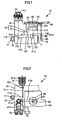
- Fig. 1 to Fig. 3 show a configuration of an embodiment of a microscope to which the present invention is applied.
- a revolver 62 is rotatably disposed at the upper right of the main body 61 of the microscope 51.
- Some objective lenses can be removably attached to this revolver 62, and the user can select an objective lens to be used by rotating the revolver 62 when necessary, and positioning a desired objective lens, out of the attached objective lenses, at a predetermined position.
- Fig. 1 shows a state where only one objective lens 120 is attached.
- a stationary plate 63 is horizontally disposed on the main body 61 above the revolver 62.
- Stages 64 and 65 are disposed along the X axis (horizontal direction in Fig. 2 ) and the Y axis (vertical direction in Fig. 2 ) respectively, with respect to the stationary plate 63, so as to be freely moved.
- an adjustment axis 68 which is disposed at the right of the revolver 62 extending downward, an adjustment element 69 and an adjustment element 70 are rotatably attached. If the user turns the adjustment element 69 or the adjustment element 70 clockwise or counterclockwise, the stage 64 or the stage 65 moves in the X axis direction or the Y axis direction respectively.
- a sample holder 60 is removably disposed on the stage 64.
- the user selects a predetermined one of the plurality of sample holders 66, according to a sample 90 to be observed, attaches the selected one onto the stage 64, and places the sample 90 thereon.
- a hole 67 is formed at the center of the sample holder 66, and luminous flux from the objective lens 120 is irradiated onto the sample 90 through this hole 67. Therefore the user can observe a predetermined position on a horizontal plane (xy plane) of the sample 90 disposed on the stage 64 by adjusting the adjustment element 69 and the adjustment element 70 by rotating.
- a focusing handle 71 is rotatably installed on the right side face of the main body 61, and a focusing handle 71' and a focusing handle 72 are rotatably installed on the left side face thereof respectively.
- the user finely moves the revolver 62, on which the objective lens 120 is attached, closer to or away from the sample 90 by turning the focusing handle 71 or the focusing handle 71' so that the focusing state by the objective lens 120 can be finely adjusted, and the user also coarsely moves the revolver 62 closer to or away from the sample 90 by turning the focusing handle 72, therefore focusing can be finely or coarsely adjusted.
- An adjustment element 75 including an adjustment element 73 for adjusting the aperture stop and an adjustment element 74 for adjusting the field stop, is rotatably installed at the lower right of the ocular 76 on the front face of the main body 61.
- the user can adjust the opening of the later mentioned stop element 117 (aperture stop 115 or field stop 116) by turning the adjustment element 75 (adjustment element 73 for adjusting the aperture stop or adjustment element 74 for adjusting the field stop).
- the ocular 76 is disposed at the upper left of the main body 61.
- the ocular 76 is located higher than the stage 64.
- the user can observe the image of the sample 90 through the ocular 76. And the user can also observe the sample 90 directly if away from the ocular 76.
- This ocular 76 may be an ocular optical system constituted by one [lens] or a plurality of lenses.
- the back of the left side face of the main body 61 is provided with a control unit 91, which is used when an optical element, such as a filter 151 and a deflecting element, which are described later with reference to Fig. 8 , is disposed on an optical path or is replaced.
- an optical element such as a filter 151 and a deflecting element, which are described later with reference to Fig. 8 .
- a housing unit 81 is disposed at the left rear of the back face of the main body 61.
- a light source 111 for illumination which is described with reference to Fig. 4 , is housed.
- a fin 81A for cooling is disposed on the side face of the housing unit 81 for releasing heat generated in the light source 111.
- the housing unit 81 is disposed in a location away from the sample holder 66 position on the stage 64 and the ocular 76, so that the heat generated from the light source 111 does not affect the sample 90, or does not cause discomfort to the user looking into the ocular 76.
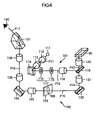
- Fig. 4 shows a configuration of an optical system inside the main body 61.
- This optical system has: an illumination optical system 101 that guides luminous flux from a light source 111 for illumination, and illuminates a sample through the objective lens 120, and an image forming optical system 102, which guides a reflected light from the sample to the ocular 76 so that the image of the sample 90 can be observed through the objective lens 120.
- the light source 111 constituted by a halogen lamp or the like emits luminous flux for illumination.
- the luminous flux for illumination travels in the sequence of a collector lens 112, relay optical system 113 and mirror 114, which are arranged in the direction of the optical path P11.
- the collector lens 112 converts divergent rays from the light source 111 into approximately parallel rays.
- the relay optical system 113 forms a light source image, which is an image of the light source 111, at a position of an aperture stop 115.
- the mirror 114 is disposed between the light source image and the relay optical system 113, and deflects the luminous flux, which travels on an optical path P11, which is directed from the light source 111 to the user (direction of the ocular 76 when viewed from the top) horizontally, to the right direction, so as to be luminous flux on an optical path P12.
- the optical path is deflected to the optical path P12 in the lateral direction when the longitudinal direction is a direction parallel with the optical path P11 closest to the light source 111, which directs downward parallel with the page face.
- the aperture stop 115, field stop 116, field lens group 118 and half mirror 119 are sequentially disposed on the optical path P12.
- the aperture stop 115 is disposed on a position of the optical path P12, where an image of the right source 111 is formed by the collector lens 112 and the relay optical system 113. If the position of the light source 111 is near the front side focal plane of the collector lens 112, the field stop 116 is roughly in a conjugate relationship with the rear side focal plane of the collector lens 112 on the optical path P12, and is disposed near a position where an image of the rear side focal plane of the collector lens 112 is formed by the relay optical system 113.
- the field lens group 118 is disposed such that the front side focal plane thereof overlaps with the field stop 116, in order to project the image of the field stop 116 on the observation surface of the sample 90.
- the half mirror 119 deflects the optical path P12 of the luminous flux for illumination from the field lens group 118 to the vertical direction (up direction in Fig. 1 ), that is an optical path P13 which is directed to the objective lens 120.
- This optical path P13 is an optical path having a center which matches the optical axis of the objective lens 120, and by the half mirror 119, the optical axis of the optical path for illumination P13, is matched with the optical axis of an optical path for observation P14, by the objective lens 120.
- the luminous flux deflected to the optical path P13 forms an image of the light source 111 at a pupil position of the objective lens 120, and becomes approximately parallel rays by the objective lens 120, and illuminates a sample 90, constituted by metal, for example.
- the image forming optical system 102 lights reflected or scattered by the sample 90 are condensed by the objective lens 120 so as to be luminous flux for observation, and the luminous flux from each point of the sample 90 becomes parallel luminous flux by the objective lens 120, and becomes the luminous flux of the optical path P14 close to the objective lens 120 which faces the direction vertically below the plane where the sample 90 is placed.
- This luminous flux is separated from the luminous flux for illumination by passing through the half mirror 119.
- the half mirror 119 and the objective lens 120 have dual functions of the illumination optical system 101 and the image forming optical system 102, and the optical path P13 becomes a common optical path of the illumination optical system 101 and the image forming optical system 102.
- a second objective lens 131 disposed on an optical path P14, converges the luminous flux transmitted through the half mirror 119, and forms an image 90I of the sample 90.
- a reticle 103 on which a scale or the like is written, so as to be viewed overlapping with the image of the sample 90, is replaceably attached.
- a mirror 132 deflects an approximately vertical optical path P14 to be approximately horizontal, that is the left direction in Fig. 1 and Fig. 4 , in order to be an optical path P15.
- a primary image which is an intermediate image of the sample formed by the second objective lens 131, is formed on the optical path P15, and the luminous flux which formed the intermediate image enters a mirror 134 via a relay lens 133, and is deflected approximately vertically in the upward direction by the mirror 134, and travels on an optical path P16.
- the relay lens 133 and relay lens 135 relay the image forming light so as to guide the primary image to the optical axis of the ocular 76.
- the luminous flux from the mirror 134 is relayed by the relay lens 133 disposed on the optical path P15 and the relay lens 135 disposed on the optical path P16 constituting the relay optical system, and enters an image forming lens 136 on the optical path P16.
- the luminous flux emitted from the image forming lens 136 is reflected by a prism 137, is split into two optical paths by an optical path dividing element, which is not illustrated, and enters the ocular 76 along an optical path P17. Therefore the user can observe an expanded image of the sample 90 via the ocular 76 with their eyes 140.
- the deflecting optical element constituted by a mirror may be constituted by a prism, not a mirror.
- the prism 137 may be constituted by a porro prism, roof prism or the like, or a mirror may be used for deflecting instead.
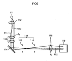
- Fig. 5 shows a relationship of the optical paths of the illumination optical system 101 and the image forming optical system 102 when viewed from the top.
- the optical path P11 for illumination and the optical path P17 of the ocular 76 are optical paths approximately parallel with the depth direction (vertical direction in Fig. 2 , horizontal direction in Fig. 3 ) of the microscope 51, and are optical paths directing from the light source 111 to the ocular 76 (the eyes of the user 140). Therefore in this configuration, the light source 111 can be disposed sufficiently distant from the user.
- the optical path P12 and the optical path P15 are optical paths approximately vertical to the optical path P11, that is, vertical to the optical path P17. Since the stage is disposed at the horizontal direction of the user, the user can easily reach the sample 90 disposed on the stage 64 while looking into the ocular 76.
- the optical path P17 may have an orthogonal relationship with the optical path P12 of the illumination optical system 101 or the optical path P15 of the image forming optical system 102 when the microscope 51 is viewed from the top, and this aspect corresponds to the present invention as well.
- the optical path P13 which is closest to the sample, of the illumination optical system 101 and the image forming optical system 102, is a common optical path [of the illumination optical system 101 and the image forming optical system 102], and can be used for vertical illumination. Therefore [the present microscope 51] is most appropriate for an inverted microscope in which a heavy sample can be easily placed on the stage, and the sample can be easily reached during microscopic observation.
- Fig. 6 shows a detailed positional relationship of the optical elements disposed on the optical path of the illumination optical system 101.
- the light source 111 and the aperture stop 115 are in a conjugate [relationship], and the rear side focal plane of the objective lens 120 in Fig. 4 is also approximately in a conjugate relationship.
- the focal plane F112 of the collector lens 112, on which lights emitted from the light source 111 parallel with the optical axis are converged by the collector lens 112, and the field stop 116, are approximately in a conjugate relationship.
- the focal plane F112 and the luminous flux that passes through the field stop 116, which is transformed into parallel rays by the field lens group 118, also enters a conjugate relationship with the observation plane of the sample 90 by the objective lens 120.
- the direction of the optical path P11 which is parallel with the optical path P17 of the ocular (vertical direction in Fig. 6 ), in other words, the direction the user faces when the user uses the microscope 51, is the longitudinal direction
- the luminous flux from the light source 111 is deflected to the lateral direction, that is the left and right directions of the user, by the mirror 114 as a deflecting element.
- the stop element 117 which is a stop element constituted by the aperture stop 115 and the field stop 116, is disposed on the optical path P12 in the lateral direction.
- the adjustment element 75 which adjusts the stop element 117 using a known structure, is disposed near the stop element 117.
- the adjustment element 75 for adjusting the stop element 117 (adjustment element 73 for adjusting the aperture stop and the adjustment element 74 for adjusting the field stop), can be disposed on the front face of the main body 61 (surface closest to the ocular 76 out of the four side faces of an approximately rectangular parallelopiped main body 61), so the user who works while keeping their eyes 140 close to the ocular 76 can easily manipulate the adjustment element.
- the depth can be decreased, and the control unit 91 can be disposed in a position close to the ocular 76, compared with the case of disposing the optical path P12 vertically on a same line with the optical path P11, which is closest to the light source 111. Therefore the user can easily execute control of such an operation as replacing a filter.
- the collector lens 112, relay optical system 113 and field lens group 118 which are disposed immediately after the light source for illumination, are combined so as to create positions to dispose the aperture stop 115, field stop 116 and filter 151.
- the objective lens 120 in order to efficiently guide light from a light source, having dimensions of a commercial product, to the objective lens 120 and illuminate a sample 90, 40 to 50 mm of an optical path length is required for the collector lens, 100 to 250 mm for the relay lens optical system, and 80 to 120 mm for the field lens group.
- about a 220 mm to 420 mm length is required for the optical paths.
- dimensions in certain directions must be taken to be very long in prior art, but according to the present invention, dimensions in all directions can be compact, while improving controllability.
- the angle between the optical path P17 closest to the ocular 76 (path P11 closest to the light source 111 that is parallel with the optical path P17) and the optical path P12, that is the angle in the lateral direction when the direction of the optical path P17 closest to the ocular 76 is the longitudinal direction, when viewed from the top, need not be exactly a right angle, but may be an obtuse or acute angle close to a right angle, only if the adjacent element 75 for adjusting the aperture stop 115 and the field stop 116 can be disposed on the front face of the main body 61 with that angle.
- the mirror 114 may be omitted, and the optical path P11 constituted by the light source 111, collector lens 112 and relay optical system 113, may be parallel with the optical path P12, in other words, the optical path of the illumination optical system 101 may be linear so that the entire system is disposed in a lateral direction (left and right direction) with respect to the optical path P17 of the ocular 76 as the longitudinal direction.
- the housing unit 81 of the light source 111 becomes close to the user. This increases the possibility for the user to touch the housing unit 81 of the light source 111 in error, and experience discomfort, so it is preferable to change the direction of the optical path so as to be the optical path P11 and the optical path P12, as shown in the present embodiment.
- the field stop 116 In order to dispose both the aperture stop 115 and the field stop 116 on the optical path P12, the field stop 116 must be close to the optical path P13 of the objective lens 120.
- the present inventor set the focal distance f1 and the distance L1 between a surface of the field lens group 118 that is most distant from the field stop 116, of the field lens group 118, and the surface of the field stop 116 along the optical axis, so as to satisfy the relationship of the following expression (1): 1 ⁇ L ⁇ 1 / f ⁇ 1 ⁇ 1.2
- the value of L1/f1 is smaller than the lower limit value, that is 1 or less, a strong telephoto ratio is demanded for the field lens group 118, and therefore aberrations, especially curvature of field, cannot be corrected.
- the curvature of field can be evaluated by a Petzval sum, but if this value exceeds ⁇ 0.015, the state of difference of the focus between the center and the edge can be visually recognized when a flat sample is observed. If the value L1/f1 is smaller than the lower limit value, it becomes difficult to maintain the value of the Petzval sum in a ⁇ 0.015 range.
- the value L1/f1 exceeds the upper limit value, that is 1.2 or more, the optical path length between the field stop 116 and the field lens group 118 becomes long, which is disadvantageous for downsizing.
- the arrangement of each component of the microscope is forced to be changed, and it becomes difficult to dispose both the aperture stop 115 and the field stop 116 on the optical path P12, and the control unit 91 becomes distant from the user, which worsens controllability.
- the value L1/f1 satisfies the relationship of expression (1).
- the mirror 114 In order to dispose the optical path P12 in a lateral direction with respect to the optical path P11 disposed in the longitudinal direction (depth direction), the mirror 114, as a deflecting element, must be disposed between the relay optical system 113 and the aperture stop 115.
- the focal distance f2 of the relay optical system 113 and the distance L2 between a surface, that is closest to the aperture stop 115, of the relay optical system 113 and the surface of the aperture stop 115 along the optical axis satisfy the relationship of the following expression (2): 0.70 ⁇ L ⁇ 2 / f ⁇ 2 ⁇ 1.0
- the aperture stop 115 is disposed at the position of the rear side focal point of the relay optical system 113, the distance between the surface, that is closest to the aperture stop 115, of the relay optical system 113 and the focal point, in other words the back focus, must be sufficiently long, in order to dispose the mirror 114 between the relay optical system 113 and the aperture stop 115. If the value L2/f2 does not reach the lower limit value, that is 0.70 or less, the space to insert the mirror 114 becomes small. This means that an effective diameter of the mirror 114 must be smaller, and as a result, the NA of illumination decreases.
- L2/f2 exceeds the upper limit value, that is 1.0 or more, on the other hand, the diameter of the luminous flux to satisfy the required illumination NA becomes too large, and aperture of the relay optical system 113 also increases. Therefore it is preferred that the value L2/f2 satisfies the relationship of expression (2).
- the value of the Petzval sum in this case is 0.014.
- a filter 151 is disposed between the collector lens 112 and the relay optical system 113, and a diffusion plate 152, for diffusing light, is disposed immediately before the aperture stop 115.
- the distance L2 is a sum of the distance L21 between the surface, that is closest to the mirror 114, of the relay optical system 113 and the mirror 114 along the center of the optical path, and the distance L22 between the mirror 114 and the aperture stop 115 along the center of the optical path.
- Fig. 9 is a diagram depicting the state of tracking rays when parallel rays are entered into the field lens group 118 shown in Fig. 8 from the half mirror 119, that is an opposite direction of the traveling direction of the illumination light.
- a lens that is distant from the field stop 116, having a surface s16 has a surface s11 which is located further from the field stop 116 and a surface s12 which is located closer to the field stop 116.
- the lens close to the field stop 116 has a surface s13 which is located further from the field stop 116, an intermediate surface s14 and a surface s15 which is located closer to the field stop 116.
- Table 1 shows the result of tracking rays in the field lens group 118 in Fig. 9 .
- the radius of curvature of the surface s11 to the surface s16 is: 60.000 mm, -60.000 mm, 35.000 mm, -40.000 mm, 75.521 mm and 0.000 mm respectively.
- the distance between the surface s11 and the adjacent surface s12 is 6 mm
- the distance between the surface s12 and the adjacent surface s13 is 0.5 mm
- the distance between the surface s13 and the adjacent surface s14 is 7.5 mm
- the distance between the surface s14 and the adjacent surface s15 is 1.5 mm
- the distance between the surface s15 and the adjacent surface s16 is 39.2 mm.
- the refractive index nd at the d-line (emission line when light source is an Na lamp) is 1.49782 in the surface s11 and surface s13, and 1.65412 in the surface s14.
- the Abbe number ⁇ d is 82.52 in the surface s11 and surface s13, and is 39.7 in the surface s14.
- Table 2 shows the lens data of the relay optical system 113 in Fig. 8 .
- the surface numbers are assigned sequentially from the surface closest to the aperture stop 115 to the light source 111.
- the lens distant from the aperture stop 115 has a surface s45 which is located further from the aperture stop 115, an intermediate surface s44 and a surface s43 which is located closer to the aperture stop 115.
- the lens closer to the aperture stop 115 has a surface s42 which is located further from the aperture stop 115, and a surface s41 which is located closer to the aperture stop 115.
- Table 2 shows the result of tracking rays in the relay optical system 113 in Fig. 8 .
- the radius of curvature and the surface distance are both in millimeter units.
- nd indicates a refractive index at the wavelength of the d-line, and ⁇ d indicates an Abbe number at the d-line as the central wavelength.
- the distance L21 between the surface closest to the mirror 114 in the relay optical system 113 and the mirror 114 along the center of the optical path is 26.4 mm, and the distance L22 between the mirror 114 and the aperture stop 115 along the center of the optical path is 30.0 mm.
- the value of the Petzval sum in this case is 0.009.
- Fig. 11 is a diagram depicting the state of tracking rays in the field lens group 118 in Fig. 10 .
- a lens that is distant from the field stop 116, having a surface s27 has a surface s21 which is located further from the field stop 116, an intermediate surface s22, and a surface s23 which is located closer to the field stop 116.
- the lens that is close to the field stop 116 has a surface s24 which is located further from the field stop 116, an intermediate surface s25, and a surface s26 which is located closer to the field stop 116.
- Table 3 shows the result of tracking rays in the field lens group 118 in Fig. 11 .
- the radius of curvature of the surface s21 to the surface s27 is: 34.800 mm, -32.300 mm, -64.922 mm, 23.120 mm, -33.500 mm, 26.450 mm and 0.000 mm respectively.
- the distance between the surface s21 and the adjacent surface s22 is 10 mm
- the distance between the surface s22 and the adjacent surface s23 is 5.0 mm
- the distance between the surface s23 and the adjacent surface s24 is 7.7 mm
- the distance between the surface s24 and the adjacent surface s25 is 12.0 mm
- the distance between the surface s25 and the adjacent surface s26 is 5 mm
- the distance between the surface s26 and the adjacent surface s27 is 18.2 mm.
- the reference index nd at the d-line is 1.49782 in the surface s21 and surface s24, 1.65412 in the surface s22 and 1.7725 in the surface s25.
- the Abbe number ⁇ d is 82.52 in the surface s21 and surface s24, and 39.7 in the surface s22 and 49.61 in the surface s25.
- Table 4 shows the lens data of the relay optical system 113 in Fig. 10 .
- the surface numbers are assigned sequentially from the surface closest to the aperture stop 115 to the light source 111.
- the lens most distant from the aperture stop 115 has a surface s58 which is located further from the aperture stop 115, and a surface s57 which is located closer to the aperture stop 115.
- the lens next distant from the aperture stop 115 has a surface s56 which is located further from the aperture stop 115, and a surface s55 which is located closer to the aperture stop 115.
- the lens second closest to the aperture stop 115 has a surface s54 which is located further from the aperture stop 115, and a surface s53 which is located closer to the aperture stop 115.
- the lens closest to the aperture stop 115 has a surface s52 which is located further from the aperture stop 115, and a surface s51 which is located closer to the aperture stop 115.
- Table 4 shows the result of tracking rays in the relay optical system 113 in Fig. 10 .
- the radius of curvature and the surface distance are both in millimeter units.
- nd indicates a refractive index at the wavelength of the d-line, and ⁇ d indicates an Abbe number at the d-line as the central wavelength.
- the distance L21 between the surface closest to the mirror 114 in the relay optical system 113 and the mirror 114 along the center of the optical path is 25.0 mm, and the distance L22 between the mirror 114 and the aperture stop 115 along the center of the optical path is 29.7 mm.
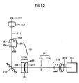
- the relay optical system 113 in Fig. 10 can be divided into a pre-stage optical system 113A and a post-stage optical system 113B, as shown in Fig. 12 , and a mirror 114 is disposed between the pre-stage optical system 113A and the post-stage optical system 113B. According to the configuration shown in Fig. 10 , however, the sample 90 and the ocular 76 can be closer, and the entire system can be more compact.
- the value of the Petzval sum in this case is 0.012.
- a filter 151 is disposed between the collector lens 112 and the relay optical system 113, and a diffusion plate 152, for diffusing light, is disposed immediately before the aperture stop 115.
- Fig. 14 is a diagram depicting the state of tracking rays in the field lens group 118 in Fig. 13 .
- a lens that is distant from the field stop 116, having a surface s36 has a surface s31 which is located further from the field stop 116, and a surface s32 which is located closer to the field stop 116.
- the lens that is close to the field stop 116 has a surface s33 which is located further from the field stop 116, an intermediate surface s34, and a surface s35 which is located closer to the field stop 116.
- Table 5 shows the result of tracking rays in the field lens group 118 in Fig. 14 .
- the radius of curvature of the surface s31 to the surface s36 is 71.000 mm, -71.000 mm, 59.000 mm, -41.500 mm, 263.308 mm and 0.000 mm respectively.
- the distance between the surface s31 and the adjacent surface s32 is 6 mm
- the distance between the surface s32 and the adjacent surface s33 is 0.5 mm
- the distance between the surface s33 and the adjacent surface s34 is 7.5 mm
- the distance between the surface s34 and the adjacent surface s35 is 1.5 mm
- the distance between the surface s35 and the adjacent surface s36 is 50.3 mm.
- the refractive index nd at the d-line is 1.49782 in the surface s31 and surface s33, and 1.654115 in the surface s34.
- the Abbe number ⁇ d is 82.52 in the surface s31 and surface s33, and 39.7 in the surface s34.
- Table 6 shows the lens data of the relay optical system 113 in Fig. 13 .
- the surface numbers are assigned sequentially from the surface closest to the aperture stop 115 to the light source 111.
- the lens that is distant from the aperture stop 115 has a surface s65 which is located further from the aperture stop 115, and an intermediate surface s64, and a surface s63 which is located closer to the aperture stop 115.
- the lens that is close to the aperture stop 115 has a surface s62 which is located further from the aperture stop 115, and a surface s61 which is located closer to the aperture stop 115.
- Table 6 shows the result of tracking rays in the relay optical system 113 in Fig. 13 .
- the radius of curvature and the surface distance are both in millimeter units.
- nd indicates a refractive index at the wavelength of the d-line, and ⁇ d indicates an Abbe number at the d-line as the central wavelength.
- the distance L21 between the surface close to the mirror 114 in the relay optical system 113 and the mirror 114 along the center of the optical path is 20.0 mm, and the distance L22 between the mirror 114 and the aperture stop 115 along the center of the optical path is 30.0 mm.
- the distances between the relay optical system 113 and the mirror 114 can be decreased in the configuration in Fig. 13 . Decreasing the distance between the relay optical system 113 and the mirror 114 means a decrease of the value L2/f2 in expression (2). If the relay optical system 113 is closer to the mirror 114, the diameter of the focused light, that is emitted from the relay optical system 113 to the aperture stop 115, can be decreased, so the diameter of the relay optical system 113 and the diameter of the mirror 114 can be decreased.
- the optical path P15 and the optical path P17 that passes through the ocular 76 are set so that these optical paths are approximately perpendicular to each other when viewed from the top. Therefore the direction of the light from the sample emitted from the ocular 76 to the user, and a part of the optical path of the image forming optical system 102, are approximately perpendicular to each other.
- the objective lens 120, revolver 62 and sample 90 are disposed at the right side to the eyes of the user. Therefore the user of the microscope 51 cannot only easily manipulate the adjustment element 75 and control element 91, but can also easily manipulate the focusing control and observation position adjustment control without moving the upper part of the body, and can also confirm [the sample] by a direct visual check.
- visibility of the objective lens 120 improves. Also controllability in switching the objective lens 120, that is accessibility to the revolver 62 for switching magnification, can be improved. Operability to replace or change the position of the sample 90 is also improved. Attachment/detachment of the reticle 103 is also easy. Since the optical element can be attached to/detached from the optical path on the front face of the main body unit 21, the upper part of the body of the user need not move when observation shifts to a replacement procedure. Therefore operability improves.
- the length of the optical path of the image forming optical system can be increased. Therefore even if a certain focal distance is required at the least, the length to sufficiently support this requirement can be secured.
- the intermediate image 90I is formed on the optical path P15, therefore the reticle 103 can be inserted into the optical path at the front face of the device. This dramatically improves controllability of the image forming optical system.
- the distance of the optical path P16 is set to be longer than the total distance of the optical path P13 and the optical path P14.
- the position of the ocular 76 can be higher than the stage 64, and the user can easily overlook the sample 90 placed on the stage 64 from above, if the view is shifted from the ocular 76, and fine adjustment of the position of the sample 90 can easily be checked visually, without changing the position of observing.
- An equivalent visibility, controllability and operability according to the present invention can be implemented when the object lens 120 is disposed at the left of the user' eyes, and is not limited to the right side.
- the optical path P13 and the optical path P14 are disposed in parallel at the right side of the optical axis of the optical path P16.
- the optical path P13 and the optical path P14 may be disposed in parallel at the left side of the optical path P16.
- each element and lens are inverted with respect to the dashed line, which indicates the center of the optical path P16, in the configuration in Fig. 1 .
- various optical elements including various filters (e.g. deflecting plate, fluorescent filter) which are not illustrated and are used for special observation, can be disposed on the optical path P12, that is a part of the optical path of the illumination optical system 101, at the front face side of the main body portion 21. Also various filters can be inserted into/removed from the optical path P14 of the image forming optical system 102 via the front face of the device. As a result, controllability of various optical elements improves.
- filters e.g. deflecting plate, fluorescent filter
- the optical paths are set to overlap on a same line.
- the space of the optical path must be secured only at one side when viewed from the optical axis direction of the objective lens 120.
- the space around the stages 64 and 65 can be saved, that is the main body portion 61 can be downsized in the lateral direction in Fig. 2 .
- the configuration of the optical system is not limited to the example shown in Fig. 1 to Fig. 4 , but is sufficient if the following is satisfied.
- the above mentioned effects can be implemented if there is a part of the optical path of the illumination optical system and an optical path of the image forming optical system that is formed approximately perpendicular to the direction of light from the sample that is emitted from the ocular 76 to the user (hereafter referred to as the "second optical path") when viewed from the top, if an optical path that is approximately parallel with the second optical path is provided also in a part of the optical path of the illumination optical system, and if the optical path of the illumination optical system is set so that at least a part of the optical path of the illumination optical system and at least a part of the second optical path overlap when viewed from a predetermined direction that is perpendicular to the above mentioned optical path [that is parallel with the second optical path] and the second optical path respectively.
- Embodiments of the present invention is not limited to the above mentioned embodiments, but can be modified in various ways within the scope not deviating from the spirit of the present invention.
- a microscope particularly an inverted microscope according to the present invention, is useful as an inspection apparatus for industrial use and as an observation apparatus for observing microstructures, and is suitable for usage for which controllability and space saving are demanded.
Abstract
Description
- The present invention relates to a microscope, and more particularly to a microscope of which visibility, controllability and operability are improved.
- Conventionally in an image forming optical system of an inverted microscope, there are an optical axis of an objective lens (hereafter referred to as an "objective optical axis"), and an optical axis constituting a part of an image forming optical path at a lens barrel side (hereafter referred to as a "lens barrel optical axis"). These objective optical axis and lens barrel optical axis are positioned at the center of the microscope unit (hereafter referred to as the "main body portion"), and are often disposed in parallel at the front and back when the side of an ocular is at the front (e.g. see Patent Document 1).
- There is a type of inverted microscope which has a light source for illumination, so that the illumination light is guided from the light source to the illumination optical system, and illuminates a sample through an objective lens. Light from the sample is condensed by the object lens and is guided to the ocular via the image forming optical system. The user can observe the image of the sample through the occular (e.g. see Patent Document 2).
- An aperture is disposed in the middle of the illumination optical system, and the user adjusts the illumination state by controlling the aperture so that the sample is appropriately illuminated.
-
- [Patent Document 1] Japanese Patent Application Laid-Open No.
2003-75726 - [Patent Document 2] Japanese Patent Application Laid-Open No.
2005-234279 - However according to the above mentioned conventional configuration of the inverted microscope, the objective optical axis is inevitably disposed in the back of the main body portion. The stop, which is in the middle of the illumination optical system, is also disposed behind the lens barrel support.
- In such a conventional inverted microscope, visibility, controllability and operability for the user are not very good. For example, it is difficult to see what kind of objective lens is currently installed. In other words, visibility of the objective lens is poor.
- Control of a revolver when magnification is changed, that is switching control of the objective lens, for example, is also difficult. Operability to replace samples or to change position of a sample is also not very good. In this way, if the optical path of the illumination optical system is positioned in the depth direction from the top view, the position of an element to control the stop is distant from the user, which makes operability poor when the user controls the stop while observing a sample through the ocular.
- With the foregoing in view, it is an object of the present invention to improve visibility, controllability and operability of an inverted microscope.
- A microscope of the present invention is a microscope having: an image forming optical system that condenses light from a sample, and guides it to an ocular optical system, and the ocular optical system that guides the light propagated on the optical path of the image forming optical system to a user, characterized in that the image forming optical system has an objective lens for condensing light from the sample, and a deflecting element for deflecting the light condensed by the objective lens, and the image forming optical system includes an optical axis of the objective lens, and includes at least a first optical path that is formed in parallel with the optical axis of the objective lens, and a second optical path that is formed by deflecting light, which propagates the first optical path, by the deflecting element, and is formed in a direction different from the first optical path, and the second optical path is formed roughly perpendicular to an emission direction of the light of the ocular optical system from the sample when viewed from the top.
- A microscope of the present invention is a microscope having an illumination optical system that guides luminous flux from a light source for illumination and illuminates a sample, and an image forming optical system that guides light from the sample to an ocular so that an image of the sample can be observed via an objective lens, characterized in that the illumination optical system has, at least on a part of thereof, an optical path that guides the luminous flux from the light source in a lateral direction when a longitudinal direction is a direction parallel with the optical path of the ocular optical system when the microscope is viewed from the top, and a stop element for limiting the luminous flux emitted from the light source is disposed on the optical path in the lateral direction.
- According to an aspect of the present invention, the illumination optical system has an optical path that guides the luminous flux from the light source in a lateral direction at least on a part of [the illumination optical system] when a longitudinal direction is a direction parallel with the optical path of the ocular optical system when the microscope is viewed from the top, and a stop for the illumination optical system is disposed on the optical path in the lateral direction.
- As described above, according to the present invention, visibility, controllability and operability of the user improve compared with prior art. For example, visibility of the objective lens, controllability of switching the objective lens, and operability of replacing and changing position of a sample improve.
-
-
Fig. 1 is a front view depicting a configuration of an embodiment of a microscope according to the present invention; -
Fig. 2 is a top view depicting the configuration of the embodiment of the microscope according to the present invention; -
Fig. 3 is a side view depicting the configuration of the embodiment of the microscope according to the present invention; -
Fig. 4 is a perspective view depicting a configuration of an illumination optical system and an image forming optical system according to the embodiment of the microscope of the present invention; -
Fig. 5 is a top view depicting a positional relationship of each optical path of the illumination optical system and the image forming optical system according to the embodiment of the microscope of the present invention; -
Fig. 6 is a top view depicting the configuration of the illumination optical system according to the embodiment of the microscope of the present invention; -
Fig. 7 is a top view depicting a positional relationship of the illumination optical system with respect to an optical path P17 according to the embodiment of the microscope of the present invention; -
Fig. 8 is a top view depicting a configuration of an illumination optical system according to an embodiment of the microscope of the present invention; -
Fig. 9 is a top view depicting a configuration of a field lens group and field stop for tracking rays; -
Fig. 10 is a top view depicting a configuration of an illumination optical system according to an embodiment of the microscope of the present invention; -
Fig. 11 is a top view depicting a configuration of a field lens group and a field stop for tracking rays; -
Fig. 12 is a top view depicting a configuration of an illumination optical system according to an embodiment of the microscope of the present invention; -
Fig. 13 is a top view depicting a configuration of an illumination optical system according to an embodiment of the microscope of the present invention; and -
Fig. 14 is a top view depicting a configuration of a field lens group and a field stop for tracking rays. -
- 51
- microscope
- 61
- main body
- 64, 65
- stage
- 71, 72
- focusing handle
- 73, 74
- adjustment element
- 76
- ocular
- 81
- housing portion
- 90
- sample
- 120
- objective lens
- 111
- light source
- 112
- collector lens
- 113
- relay optical system
- 114
- mirror
- 115
- aperture stop
- 116
- field stop
- 117
- stop element
- 118
- field lens group
- 119
- half mirror
- Embodiments of the present invention will now be described with reference to the drawings.
-
Fig. 1 to Fig. 3 show a configuration of an embodiment of a microscope to which the present invention is applied. Arevolver 62 is rotatably disposed at the upper right of themain body 61 of themicroscope 51. Some objective lenses can be removably attached to thisrevolver 62, and the user can select an objective lens to be used by rotating therevolver 62 when necessary, and positioning a desired objective lens, out of the attached objective lenses, at a predetermined position.Fig. 1 shows a state where only oneobjective lens 120 is attached. - A
stationary plate 63 is horizontally disposed on themain body 61 above therevolver 62.Stages Fig. 2 ) and the Y axis (vertical direction inFig. 2 ) respectively, with respect to thestationary plate 63, so as to be freely moved. At the bottom of anadjustment axis 68 which is disposed at the right of therevolver 62 extending downward, anadjustment element 69 and anadjustment element 70 are rotatably attached. If the user turns theadjustment element 69 or theadjustment element 70 clockwise or counterclockwise, thestage 64 or thestage 65 moves in the X axis direction or the Y axis direction respectively. - A sample holder 60 is removably disposed on the
stage 64. The user selects a predetermined one of the plurality ofsample holders 66, according to asample 90 to be observed, attaches the selected one onto thestage 64, and places thesample 90 thereon. Ahole 67 is formed at the center of thesample holder 66, and luminous flux from theobjective lens 120 is irradiated onto thesample 90 through thishole 67. Therefore the user can observe a predetermined position on a horizontal plane (xy plane) of thesample 90 disposed on thestage 64 by adjusting theadjustment element 69 and theadjustment element 70 by rotating. - A focusing
handle 71 is rotatably installed on the right side face of themain body 61, and a focusing handle 71' and a focusinghandle 72 are rotatably installed on the left side face thereof respectively. The user finely moves therevolver 62, on which theobjective lens 120 is attached, closer to or away from thesample 90 by turning the focusinghandle 71 or the focusing handle 71' so that the focusing state by theobjective lens 120 can be finely adjusted, and the user also coarsely moves therevolver 62 closer to or away from thesample 90 by turning the focusinghandle 72, therefore focusing can be finely or coarsely adjusted. - An
adjustment element 75, including anadjustment element 73 for adjusting the aperture stop and anadjustment element 74 for adjusting the field stop, is rotatably installed at the lower right of the ocular 76 on the front face of themain body 61. The user can adjust the opening of the later mentioned stop element 117 (aperture stop 115 or field stop 116) by turning the adjustment element 75 (adjustment element 73 for adjusting the aperture stop oradjustment element 74 for adjusting the field stop). A reticle attaching area for inserting/removing areticle 103, on which a scale is written so that the scale is visible overlapping with the image of thesample 90, is also disposed on the front face of themain body 61. - The ocular 76 is disposed at the upper left of the
main body 61. The ocular 76 is located higher than thestage 64. The user can observe the image of thesample 90 through the ocular 76. And the user can also observe thesample 90 directly if away from theocular 76. This ocular 76 may be an ocular optical system constituted by one [lens] or a plurality of lenses. - The back of the left side face of the
main body 61 is provided with acontrol unit 91, which is used when an optical element, such as afilter 151 and a deflecting element, which are described later with reference toFig. 8 , is disposed on an optical path or is replaced. - A
housing unit 81 is disposed at the left rear of the back face of themain body 61. In thehousing unit 81, alight source 111 for illumination, which is described with reference toFig. 4 , is housed. Afin 81A for cooling is disposed on the side face of thehousing unit 81 for releasing heat generated in thelight source 111. Thehousing unit 81 is disposed in a location away from thesample holder 66 position on thestage 64 and the ocular 76, so that the heat generated from thelight source 111 does not affect thesample 90, or does not cause discomfort to the user looking into theocular 76. -
Fig. 4 shows a configuration of an optical system inside themain body 61. This optical system has: an illuminationoptical system 101 that guides luminous flux from alight source 111 for illumination, and illuminates a sample through theobjective lens 120, and an image formingoptical system 102, which guides a reflected light from the sample to the ocular 76 so that the image of thesample 90 can be observed through theobjective lens 120. - In the illumination
optical system 101, thelight source 111 constituted by a halogen lamp or the like emits luminous flux for illumination. The luminous flux for illumination travels in the sequence of acollector lens 112, relayoptical system 113 andmirror 114, which are arranged in the direction of the optical path P11. Thecollector lens 112 converts divergent rays from thelight source 111 into approximately parallel rays. The relayoptical system 113 forms a light source image, which is an image of thelight source 111, at a position of anaperture stop 115. Themirror 114 is disposed between the light source image and the relayoptical system 113, and deflects the luminous flux, which travels on an optical path P11, which is directed from thelight source 111 to the user (direction of the ocular 76 when viewed from the top) horizontally, to the right direction, so as to be luminous flux on an optical path P12. In other words, in the case ofFig. 2 which is a top view of the microscope, the optical path is deflected to the optical path P12 in the lateral direction when the longitudinal direction is a direction parallel with the optical path P11 closest to thelight source 111, which directs downward parallel with the page face. - The
aperture stop 115,field stop 116,field lens group 118 andhalf mirror 119 are sequentially disposed on the optical path P12. Theaperture stop 115 is disposed on a position of the optical path P12, where an image of theright source 111 is formed by thecollector lens 112 and the relayoptical system 113. If the position of thelight source 111 is near the front side focal plane of thecollector lens 112, thefield stop 116 is roughly in a conjugate relationship with the rear side focal plane of thecollector lens 112 on the optical path P12, and is disposed near a position where an image of the rear side focal plane of thecollector lens 112 is formed by the relayoptical system 113. Thefield lens group 118 is disposed such that the front side focal plane thereof overlaps with thefield stop 116, in order to project the image of thefield stop 116 on the observation surface of thesample 90. - The
half mirror 119, as a luminous flux combining element, deflects the optical path P12 of the luminous flux for illumination from thefield lens group 118 to the vertical direction (up direction inFig. 1 ), that is an optical path P13 which is directed to theobjective lens 120. This optical path P13 is an optical path having a center which matches the optical axis of theobjective lens 120, and by thehalf mirror 119, the optical axis of the optical path for illumination P13, is matched with the optical axis of an optical path for observation P14, by theobjective lens 120. The luminous flux deflected to the optical path P13 forms an image of thelight source 111 at a pupil position of theobjective lens 120, and becomes approximately parallel rays by theobjective lens 120, and illuminates asample 90, constituted by metal, for example. - In the image forming
optical system 102, lights reflected or scattered by thesample 90 are condensed by theobjective lens 120 so as to be luminous flux for observation, and the luminous flux from each point of thesample 90 becomes parallel luminous flux by theobjective lens 120, and becomes the luminous flux of the optical path P14 close to theobjective lens 120 which faces the direction vertically below the plane where thesample 90 is placed. This luminous flux is separated from the luminous flux for illumination by passing through thehalf mirror 119. In other words, thehalf mirror 119 and theobjective lens 120 have dual functions of the illuminationoptical system 101 and the image formingoptical system 102, and the optical path P13 becomes a common optical path of the illuminationoptical system 101 and the image formingoptical system 102. A secondobjective lens 131, disposed on an optical path P14, converges the luminous flux transmitted through thehalf mirror 119, and forms an image 90I of thesample 90. At this position, areticle 103, on which a scale or the like is written, so as to be viewed overlapping with the image of thesample 90, is replaceably attached. - A
mirror 132 deflects an approximately vertical optical path P14 to be approximately horizontal, that is the left direction inFig. 1 andFig. 4 , in order to be an optical path P15. This means that the optical path P15 is approximately parallel with the optical path P12, and these paths are positioned on a same line from the top view, as shown inFig. 2 . - A primary image, which is an intermediate image of the sample formed by the second
objective lens 131, is formed on the optical path P15, and the luminous flux which formed the intermediate image enters amirror 134 via arelay lens 133, and is deflected approximately vertically in the upward direction by themirror 134, and travels on an optical path P16. Therelay lens 133 andrelay lens 135 relay the image forming light so as to guide the primary image to the optical axis of the ocular 76. The luminous flux from themirror 134 is relayed by therelay lens 133 disposed on the optical path P15 and therelay lens 135 disposed on the optical path P16 constituting the relay optical system, and enters animage forming lens 136 on the optical path P16. The luminous flux emitted from theimage forming lens 136 is reflected by aprism 137, is split into two optical paths by an optical path dividing element, which is not illustrated, and enters the ocular 76 along an optical path P17. Therefore the user can observe an expanded image of thesample 90 via the ocular 76 with theireyes 140. - As
Fig. 4 shows, the deflecting optical element constituted by a mirror may be constituted by a prism, not a mirror. Theprism 137 may be constituted by a porro prism, roof prism or the like, or a mirror may be used for deflecting instead. -
Fig. 5 shows a relationship of the optical paths of the illuminationoptical system 101 and the image formingoptical system 102 when viewed from the top. The optical path P11 for illumination and the optical path P17 of the ocular 76 are optical paths approximately parallel with the depth direction (vertical direction inFig. 2 , horizontal direction inFig. 3 ) of themicroscope 51, and are optical paths directing from thelight source 111 to the ocular 76 (the eyes of the user 140). Therefore in this configuration, thelight source 111 can be disposed sufficiently distant from the user. The optical path P12 and the optical path P15 are optical paths approximately vertical to the optical path P11, that is, vertical to the optical path P17. Since the stage is disposed at the horizontal direction of the user, the user can easily reach thesample 90 disposed on thestage 64 while looking into theocular 76. - If the ocular 76 can rotate the optical axis direction thereof with respect to the optical path P16, at least the optical path P17 may have an orthogonal relationship with the optical path P12 of the illumination
optical system 101 or the optical path P15 of the image formingoptical system 102 when themicroscope 51 is viewed from the top, and this aspect corresponds to the present invention as well. In thismicroscope 51, the optical path P13, which is closest to the sample, of the illuminationoptical system 101 and the image formingoptical system 102, is a common optical path [of the illuminationoptical system 101 and the image forming optical system 102], and can be used for vertical illumination. Therefore [the present microscope 51] is most appropriate for an inverted microscope in which a heavy sample can be easily placed on the stage, and the sample can be easily reached during microscopic observation. -
Fig. 6 shows a detailed positional relationship of the optical elements disposed on the optical path of the illuminationoptical system 101. Thelight source 111 and theaperture stop 115 are in a conjugate [relationship], and the rear side focal plane of theobjective lens 120 inFig. 4 is also approximately in a conjugate relationship. The focal plane F112 of thecollector lens 112, on which lights emitted from thelight source 111 parallel with the optical axis are converged by thecollector lens 112, and thefield stop 116, are approximately in a conjugate relationship. The focal plane F112 and the luminous flux that passes through thefield stop 116, which is transformed into parallel rays by thefield lens group 118, also enters a conjugate relationship with the observation plane of thesample 90 by theobjective lens 120. - In this way, according to the present embodiment, when the direction of the optical path P11, which is parallel with the optical path P17 of the ocular (vertical direction in
Fig. 6 ), in other words, the direction the user faces when the user uses themicroscope 51, is the longitudinal direction, the luminous flux from thelight source 111 is deflected to the lateral direction, that is the left and right directions of the user, by themirror 114 as a deflecting element. And thestop element 117, which is a stop element constituted by theaperture stop 115 and thefield stop 116, is disposed on the optical path P12 in the lateral direction. Theadjustment element 75, which adjusts thestop element 117 using a known structure, is disposed near thestop element 117. Therefore theadjustment element 75, for adjusting the stop element 117 (adjustment element 73 for adjusting the aperture stop and theadjustment element 74 for adjusting the field stop), can be disposed on the front face of the main body 61 (surface closest to the ocular 76 out of the four side faces of an approximately rectangular parallelopiped main body 61), so the user who works while keeping theireyes 140 close to the ocular 76 can easily manipulate the adjustment element. - Since the optical path P12 is disposed in the horizontal direction, the depth can be decreased, and the
control unit 91 can be disposed in a position close to the ocular 76, compared with the case of disposing the optical path P12 vertically on a same line with the optical path P11, which is closest to thelight source 111. Therefore the user can easily execute control of such an operation as replacing a filter. - In the illumination optical system, the
collector lens 112, relayoptical system 113 andfield lens group 118, which are disposed immediately after the light source for illumination, are combined so as to create positions to dispose theaperture stop 115,field stop 116 andfilter 151. Generally in order to efficiently guide light from a light source, having dimensions of a commercial product, to theobjective lens 120 and illuminate asample 90, 40 to 50 mm of an optical path length is required for the collector lens, 100 to 250 mm for the relay lens optical system, and 80 to 120 mm for the field lens group. As a result, about a 220 mm to 420 mm length is required for the optical paths. In order to secure such a long optical path length, dimensions in certain directions must be taken to be very long in prior art, but according to the present invention, dimensions in all directions can be compact, while improving controllability. - The angle between the optical path P17 closest to the ocular 76 (path P11 closest to the
light source 111 that is parallel with the optical path P17) and the optical path P12, that is the angle in the lateral direction when the direction of the optical path P17 closest to the ocular 76 is the longitudinal direction, when viewed from the top, need not be exactly a right angle, but may be an obtuse or acute angle close to a right angle, only if theadjacent element 75 for adjusting theaperture stop 115 and thefield stop 116 can be disposed on the front face of themain body 61 with that angle. - As
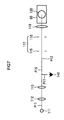
Fig. 7 shows, in the illuminationoptical system 101, themirror 114 may be omitted, and the optical path P11 constituted by thelight source 111,collector lens 112 and relayoptical system 113, may be parallel with the optical path P12, in other words, the optical path of the illuminationoptical system 101 may be linear so that the entire system is disposed in a lateral direction (left and right direction) with respect to the optical path P17 of the ocular 76 as the longitudinal direction. However if the optical path of the illuminationoptical system 101 is linear, thehousing unit 81 of thelight source 111 becomes close to the user. This increases the possibility for the user to touch thehousing unit 81 of thelight source 111 in error, and experience discomfort, so it is preferable to change the direction of the optical path so as to be the optical path P11 and the optical path P12, as shown in the present embodiment. - In order to dispose both the
aperture stop 115 and thefield stop 116 on the optical path P12, thefield stop 116 must be close to the optical path P13 of theobjective lens 120. For this, the present inventor set the focal distance f1 and the distance L1 between a surface of thefield lens group 118 that is most distant from thefield stop 116, of thefield lens group 118, and the surface of thefield stop 116 along the optical axis, so as to satisfy the relationship of the following expression (1):
- If the value of L1/f1 is smaller than the lower limit value, that is 1 or less, a strong telephoto ratio is demanded for the
field lens group 118, and therefore aberrations, especially curvature of field, cannot be corrected. In concrete terms, the curvature of field can be evaluated by a Petzval sum, but if this value exceeds ±0.015, the state of difference of the focus between the center and the edge can be visually recognized when a flat sample is observed. If the value L1/f1 is smaller than the lower limit value, it becomes difficult to maintain the value of the Petzval sum in a ±0.015 range. If parallel rays enter thefield lens group 118 from a direction of thehalf mirror 119, which is opposite of the illumination light advancing direction, the rays are tracked, and the parallel rays form an image on the plane of thefield stop 116. In this case, if the value of the Petzval sum is large, a curvature of field is generated, and when the image of thefield stop 116 overlaps with thesample 90 during observation, the focusing plane shifts depending on the numerical aperture of thefield stop 116, and controllability deteriorates. - If the value L1/f1 exceeds the upper limit value, that is 1.2 or more, the optical path length between the
field stop 116 and thefield lens group 118 becomes long, which is disadvantageous for downsizing.
As a result, the arrangement of each component of the microscope is forced to be changed, and it becomes difficult to dispose both theaperture stop 115 and thefield stop 116 on the optical path P12, and thecontrol unit 91 becomes distant from the user, which worsens controllability. Hence it is preferable that the value L1/f1 satisfies the relationship of expression (1). - In order to dispose the optical path P12 in a lateral direction with respect to the optical path P11 disposed in the longitudinal direction (depth direction), the
mirror 114, as a deflecting element, must be disposed between the relayoptical system 113 and theaperture stop 115. For this, the present inventor discovered that the focal distance f2 of the relayoptical system 113 and the distance L2 between a surface, that is closest to theaperture stop 115, of the relayoptical system 113 and the surface of theaperture stop 115 along the optical axis, satisfy the relationship of the following expression (2):
- Since the
aperture stop 115 is disposed at the position of the rear side focal point of the relayoptical system 113, the distance between the surface, that is closest to theaperture stop 115, of the relayoptical system 113 and the focal point, in other words the back focus, must be sufficiently long, in order to dispose themirror 114 between the relayoptical system 113 and theaperture stop 115. If the value L2/f2 does not reach the lower limit value, that is 0.70 or less, the space to insert themirror 114 becomes small. This means that an effective diameter of themirror 114 must be smaller, and as a result, the NA of illumination decreases. If L2/f2 exceeds the upper limit value, that is 1.0 or more, on the other hand, the diameter of the luminous flux to satisfy the required illumination NA becomes too large, and aperture of the relayoptical system 113 also increases. Therefore it is preferred that the value L2/f2 satisfies the relationship of expression (2). -
Fig. 8 shows a configuration of the illuminationoptical system 101 when L1 = 54.7 mm and f1 = 50 mm, that is L1/f1 = 1.09 in expression (1), and L2 = 56.4 mm and f2 = 67.7 mm, that is L2/f2 = 0.83 in expression (2). The value of the Petzval sum in this case is 0.014. InFig. 8 , afilter 151 is disposed between thecollector lens 112 and the relayoptical system 113, and adiffusion plate 152, for diffusing light, is disposed immediately before theaperture stop 115. The distance L2 is a sum of the distance L21 between the surface, that is closest to themirror 114, of the relayoptical system 113 and themirror 114 along the center of the optical path, and the distance L22 between themirror 114 and theaperture stop 115 along the center of the optical path. -
Fig. 9 is a diagram depicting the state of tracking rays when parallel rays are entered into thefield lens group 118 shown inFig. 8 from thehalf mirror 119, that is an opposite direction of the traveling direction of the illumination light. Out of the two lenses constituting thefield lens group 118, a lens that is distant from thefield stop 116, having a surface s16, has a surface s11 which is located further from thefield stop 116 and a surface s12 which is located closer to thefield stop 116. The lens close to thefield stop 116 has a surface s13 which is located further from thefield stop 116, an intermediate surface s14 and a surface s15 which is located closer to thefield stop 116. -
Table 1 Surface Radius of curvature Surface distance nd νd s11 60.000 6 1.49782 82.52 s12 -60.000 0.5 s13 35.000 7.5 1.49782 82.52 s14 -40.000 1.5 1.65412 39.7 s15 75.521 39.2 s16 0.000 - Table 1 shows the result of tracking rays in the
field lens group 118 inFig. 9 . The radius of curvature of the surface s11 to the surface s16 is: 60.000 mm, -60.000 mm, 35.000 mm, -40.000 mm, 75.521 mm and 0.000 mm respectively. - The distance between the surface s11 and the adjacent surface s12 is 6 mm, the distance between the surface s12 and the adjacent surface s13 is 0.5 mm, the distance between the surface s13 and the adjacent surface s14 is 7.5 mm, the distance between the surface s14 and the adjacent surface s15 is 1.5 mm, and the distance between the surface s15 and the adjacent surface s16 is 39.2 mm.
- The refractive index nd at the d-line (emission line when light source is an Na lamp) is 1.49782 in the surface s11 and surface s13, and 1.65412 in the surface s14. The Abbe number νd is 82.52 in the surface s11 and surface s13, and is 39.7 in the surface s14.
- Table 2 shows the lens data of the relay
optical system 113 inFig. 8 . The surface numbers are assigned sequentially from the surface closest to theaperture stop 115 to thelight source 111. Out of the two lenses constituting the relayoptical system 113, the lens distant from theaperture stop 115 has a surface s45 which is located further from theaperture stop 115, an intermediate surface s44 and a surface s43 which is located closer to theaperture stop 115. The lens closer to theaperture stop 115 has a surface s42 which is located further from theaperture stop 115, and a surface s41 which is located closer to theaperture stop 115. -
Table 2 Surface Radius of curvature Surface distance nd νd s41 78.750 7 1.5168 64.1 s42 -78.750 50 s43 53.506 10 1.5168 64.1 s44 -35.930 2 1.72916 54.66 s45 0.000 - Table 2 shows the result of tracking rays in the relay
optical system 113 inFig. 8 . The radius of curvature and the surface distance are both in millimeter units. nd indicates a refractive index at the wavelength of the d-line, and νd indicates an Abbe number at the d-line as the central wavelength. - The distance L21 between the surface closest to the
mirror 114 in the relayoptical system 113 and themirror 114 along the center of the optical path is 26.4 mm, and the distance L22 between themirror 114 and theaperture stop 115 along the center of the optical path is 30.0 mm. -
Fig. 10 shows a configuration of the illuminationoptical system 101 when L1 = 57.9 mm and f1 = 50 mm, that is L1/f1 = 1.16, in expression (1), and L2 = 54.7 mm and f2 = 69.7 mm, that is L2/f2 = 0.78 in expression (2). The value of the Petzval sum in this case is 0.009. -
Fig. 11 is a diagram depicting the state of tracking rays in thefield lens group 118 inFig. 10 . Out of the two lenses constituting thefield lens group 118, a lens that is distant from thefield stop 116, having a surface s27, has a surface s21 which is located further from thefield stop 116, an intermediate surface s22, and a surface s23 which is located closer to thefield stop 116. The lens that is close to thefield stop 116 has a surface s24 which is located further from thefield stop 116, an intermediate surface s25, and a surface s26 which is located closer to thefield stop 116. -
Table 3 Surface Radius of curvature Surface distance nd νd s21 34.800 10 1.49782 82.52 s22 -32.300 5 1.65412 39.7 s23 -64.922 7.7 s24 23.120 12 1.49782 82.52 s25 -33.500 5 1.7725 49.61 s26 26.450 18.2 s27 0.000 - Table 3 shows the result of tracking rays in the
field lens group 118 inFig. 11 . The radius of curvature of the surface s21 to the surface s27 is: 34.800 mm, -32.300 mm, -64.922 mm, 23.120 mm, -33.500 mm, 26.450 mm and 0.000 mm respectively. - The distance between the surface s21 and the adjacent surface s22 is 10 mm, the distance between the surface s22 and the adjacent surface s23 is 5.0 mm, the distance between the surface s23 and the adjacent surface s24 is 7.7 mm, the distance between the surface s24 and the adjacent surface s25 is 12.0 mm, the distance between the surface s25 and the adjacent surface s26 is 5 mm, and the distance between the surface s26 and the adjacent surface s27 is 18.2 mm.
- The reference index nd at the d-line is 1.49782 in the surface s21 and surface s24, 1.65412 in the surface s22 and 1.7725 in the surface s25. The Abbe number νd is 82.52 in the surface s21 and surface s24, and 39.7 in the surface s22 and 49.61 in the surface s25.
- Table 4 shows the lens data of the relay
optical system 113 inFig. 10 . The surface numbers are assigned sequentially from the surface closest to theaperture stop 115 to thelight source 111. Out of the four lenses constituting the relayoptical system 113, the lens most distant from theaperture stop 115 has a surface s58 which is located further from theaperture stop 115, and a surface s57 which is located closer to theaperture stop 115. The lens next distant from theaperture stop 115 has a surface s56 which is located further from theaperture stop 115, and a surface s55 which is located closer to theaperture stop 115. The lens second closest to theaperture stop 115 has a surface s54 which is located further from theaperture stop 115, and a surface s53 which is located closer to theaperture stop 115. The lens closest to theaperture stop 115 has a surface s52 which is located further from theaperture stop 115, and a surface s51 which is located closer to theaperture stop 115. -
Table 4 Surface Radius of curvature Surface distance nd Nd s51 0.000 12.0 1.62041 60.29 s52 -58.181 0.2 s53 95.419 12.0 1.62041 60.29 s54 0.000 118.6 s55 -49.024 2.5 1.7725 49.61 s56 80.000 17.7 s57 115.822 7.0 1.48749 70.41 s58 -44.878 - Table 4 shows the result of tracking rays in the relay
optical system 113 inFig. 10 . The radius of curvature and the surface distance are both in millimeter units. nd indicates a refractive index at the wavelength of the d-line, and νd indicates an Abbe number at the d-line as the central wavelength. - The distance L21 between the surface closest to the
mirror 114 in the relayoptical system 113 and themirror 114 along the center of the optical path is 25.0 mm, and the distance L22 between themirror 114 and theaperture stop 115 along the center of the optical path is 29.7 mm. - The relay
optical system 113 inFig. 10 can be divided into a pre-stageoptical system 113A and a post-stageoptical system 113B, as shown inFig. 12 , and amirror 114 is disposed between the pre-stageoptical system 113A and the post-stageoptical system 113B. According to the configuration shown inFig. 10 , however, thesample 90 and the ocular 76 can be closer, and the entire system can be more compact. -
Fig. 13 shows a configuration of the illuminationoptical system 101 when L1 = 65.8 mm and f1 = 60 mm, that is L1/f1 = 1.10 in expression (1), and L2 = 50.0 mm and f2 = 67.7 mm, that is L2/f2 = 0.74 in expression (2). The value of the Petzval sum in this case is 0.012. InFig. 13 , just like the case ofFig. 8 , afilter 151 is disposed between thecollector lens 112 and the relayoptical system 113, and adiffusion plate 152, for diffusing light, is disposed immediately before theaperture stop 115. -
Fig. 14 is a diagram depicting the state of tracking rays in thefield lens group 118 inFig. 13 . Out of the two lenses constituting thefield lens group 118, a lens that is distant from thefield stop 116, having a surface s36, has a surface s31 which is located further from thefield stop 116, and a surface s32 which is located closer to thefield stop 116. The lens that is close to thefield stop 116 has a surface s33 which is located further from thefield stop 116, an intermediate surface s34, and a surface s35 which is located closer to thefield stop 116. -
Table 5 Surface Radius of curvature Surface distance nd νd s31 71.000 6 1.49782 82.52 s32 -71.000 0.5 s33 59.000 7.5 1.49782 82.52 s34 -41.500 1.5 1.654115 39.7 s35 263.308 50.3 s36 0.000 - Table 5 shows the result of tracking rays in the
field lens group 118 inFig. 14 . The radius of curvature of the surface s31 to the surface s36 is 71.000 mm, -71.000 mm, 59.000 mm, -41.500 mm, 263.308 mm and 0.000 mm respectively. - The distance between the surface s31 and the adjacent surface s32 is 6 mm, the distance between the surface s32 and the adjacent surface s33 is 0.5 mm, the distance between the surface s33 and the adjacent surface s34 is 7.5 mm, the distance between the surface s34 and the adjacent surface s35 is 1.5 mm, and the distance between the surface s35 and the adjacent surface s36 is 50.3 mm.
- The refractive index nd at the d-line is 1.49782 in the surface s31 and surface s33, and 1.654115 in the surface s34. The Abbe number νd is 82.52 in the surface s31 and surface s33, and 39.7 in the surface s34.
- Table 6 shows the lens data of the relay
optical system 113 inFig. 13 . The surface numbers are assigned sequentially from the surface closest to theaperture stop 115 to thelight source 111. Out of the two lenses constituting the relayoptical system 113, the lens that is distant from theaperture stop 115 has a surface s65 which is located further from theaperture stop 115, and an intermediate surface s64, and a surface s63 which is located closer to theaperture stop 115.
The lens that is close to theaperture stop 115 has a surface s62 which is located further from theaperture stop 115, and a surface s61 which is located closer to theaperture stop 115. -
Table 6 Surface Radius of curvature Surface distance nd νd s61 78.750 7 1.5168 64.1 s62 -78.750 50 s63 53.506 10 1.5168 64.1 s64 -35.930 2 1.72916 54.66 s65 0.000 - Table 6 shows the result of tracking rays in the relay
optical system 113 inFig. 13 . The radius of curvature and the surface distance are both in millimeter units. nd indicates a refractive index at the wavelength of the d-line, and νd indicates an Abbe number at the d-line as the central wavelength. - The distance L21 between the surface close to the
mirror 114 in the relayoptical system 113 and themirror 114 along the center of the optical path is 20.0 mm, and the distance L22 between themirror 114 and theaperture stop 115 along the center of the optical path is 30.0 mm. - Compared with the configurations in
Fig. 8 andFig. 10 , the distances between the relayoptical system 113 and themirror 114 can be decreased in the configuration inFig. 13 . Decreasing the distance between the relayoptical system 113 and themirror 114 means a decrease of the value L2/f2 in expression (2). If the relayoptical system 113 is closer to themirror 114, the diameter of the focused light, that is emitted from the relayoptical system 113 to theaperture stop 115, can be decreased, so the diameter of the relayoptical system 113 and the diameter of themirror 114 can be decreased. - If the diameter is too small to reach the lower limit value of expression (2), however, the relay
optical system 113 and themirror 114 contact, and if the diameter is decreased while preventing this contact, the necessary luminous flux diameter cannot be secured, and the NA of illumination decreases, as mentioned above. - In the case of the
microscope 51 according to the embodiment of the present invention, the optical path P15 and the optical path P17 that passes through the ocular 76 are set so that these optical paths are approximately perpendicular to each other when viewed from the top. Therefore the direction of the light from the sample emitted from the ocular 76 to the user, and a part of the optical path of the image formingoptical system 102, are approximately perpendicular to each other. - Because of this, the
objective lens 120,revolver 62 andsample 90 are disposed at the right side to the eyes of the user. Therefore the user of themicroscope 51 cannot only easily manipulate theadjustment element 75 andcontrol element 91, but can also easily manipulate the focusing control and observation position adjustment control without moving the upper part of the body, and can also confirm [the sample] by a direct visual check. - In concrete terms, visibility of the
objective lens 120 improves. Also controllability in switching theobjective lens 120, that is accessibility to therevolver 62 for switching magnification, can be improved. Operability to replace or change the position of thesample 90 is also improved. Attachment/detachment of thereticle 103 is also easy. Since the optical element can be attached to/detached from the optical path on the front face of the main body unit 21, the upper part of the body of the user need not move when observation shifts to a replacement procedure. Therefore operability improves. - If an optical path in a lateral direction with respect to the emission optical axis of the ocular 76 is formed in the image forming optical system, as seen in the optical path P15, the length of the optical path of the image forming optical system can be increased. Therefore even if a certain focal distance is required at the least, the length to sufficiently support this requirement can be secured.
- The intermediate image 90I is formed on the optical path P15, therefore the
reticle 103 can be inserted into the optical path at the front face of the device. This dramatically improves controllability of the image forming optical system. - Furthermore, the distance of the optical path P16 is set to be longer than the total distance of the optical path P13 and the optical path P14. Hence the position of the ocular 76 can be higher than the
stage 64, and the user can easily overlook thesample 90 placed on thestage 64 from above, if the view is shifted from the ocular 76, and fine adjustment of the position of thesample 90 can easily be checked visually, without changing the position of observing. - An equivalent visibility, controllability and operability according to the present invention can be implemented when the
object lens 120 is disposed at the left of the user' eyes, and is not limited to the right side. - In other words, the optical path P13 and the optical path P14 are disposed in parallel at the right side of the optical axis of the optical path P16.
However the optical path P13 and the optical path P14 may be disposed in parallel at the left side of the optical path P16. In this case, each element and lens are inverted with respect to the dashed line, which indicates the center of the optical path P16, in the configuration inFig. 1 . - Then in addition to the
aperture stop 115 andfield stop 116 inFig. 1 , various optical elements, including various filters (e.g. deflecting plate, fluorescent filter) which are not illustrated and are used for special observation, can be disposed on the optical path P12, that is a part of the optical path of the illuminationoptical system 101, at the front face side of the main body portion 21. Also various filters can be inserted into/removed from the optical path P14 of the image formingoptical system 102 via the front face of the device. As a result, controllability of various optical elements improves. - When the optical path P15 of the image forming
optical system 102 and the optical path P12 of the illuminationoptical system 101 are viewed vertically down from the top face (up) inFig. 2 , in other words, from the top face as shown inFig. 2 , which is in the direction perpendicular to the optical path P15 and the optical path P12, the optical paths are set to overlap on a same line. - Because of this, the space of the optical path must be secured only at one side when viewed from the optical axis direction of the
objective lens 120. As a result, the space around thestages main body portion 61 can be downsized in the lateral direction inFig. 2 . - In order to implement the above mentioned effect of improving visibility, controllability and operability, and the effect of downsizing the
main body portion 61 in the lateral direction, the configuration of the optical system is not limited to the example shown inFig. 1 to Fig. 4 , but is sufficient if the following is satisfied. In other words, the above mentioned effects can be implemented if there is a part of the optical path of the illumination optical system and an optical path of the image forming optical system that is formed approximately perpendicular to the direction of light from the sample that is emitted from the ocular 76 to the user (hereafter referred to as the "second optical path") when viewed from the top, if an optical path that is approximately parallel with the second optical path is provided also in a part of the optical path of the illumination optical system, and if the optical path of the illumination optical system is set so that at least a part of the optical path of the illumination optical system and at least a part of the second optical path overlap when viewed from a predetermined direction that is perpendicular to the above mentioned optical path [that is parallel with the second optical path] and the second optical path respectively. - Embodiments of the present invention is not limited to the above mentioned embodiments, but can be modified in various ways within the scope not deviating from the spirit of the present invention.
- As described above, a microscope, particularly an inverted microscope according to the present invention, is useful as an inspection apparatus for industrial use and as an observation apparatus for observing microstructures, and is suitable for usage for which controllability and space saving are demanded.
Claims (11)
- A microscope, comprising an image forming optical system that condenses light from a sample, includes an ocular optical system, and guides the light from said sample, characterized in that
said image forming optical system has an objective lens for condensing light from said sample and a deflecting element for deflecting the light condensed by said objective lens, and
said image forming optical system includes an optical axis of said objective lens, and includes at least a first optical path that is formed in parallel with the optical axis of said objective lens, and
a second optical path that is formed by deflecting light, which propagates said first optical path, by said deflecting element, and is formed in a direction different from said first optical path, and
said second optical path is formed approximately perpendicular to an emission direction of the light of said ocular optical system from said sample when viewed from the top. - The microscope according to Claim 1, further comprising an illumination optical system that guides illumination light to said sample via said objective lines, and characterized in that
an optical path of said illumination optical system is set such that a part of the optical path of said illumination optical system is parallel with said second optical path, and a part of the optical path of said illumination optical system and at least a part of said second optical path overlap when viewed from a predetermined direction, that is perpendicular to a part of the optical path of said illumination optical system and said optical system respectively. - The microscope according to Claim 1 or Claim 2, characterized in that
a part of an optical path at the sample side of said first optical path of said image forming optical system and a part of an optical path at the sample side of the optical path of said illumination optical system are shared,
said objective lens is a part of said illumination optical system, and
said objective lens is disposed below said sample. - The microscope according to Claim 1 or Claim 2, characterized in that said image forming optical system forms an image of said sample on said second optical path, and a reticle can be disposed at a position on said second optical path where the image of said sample is formed.
- The microscope according to any one of Claim 1 to Claim 3, characterized in that
a stop to limit luminous flux of said illumination optical system is provided on the optical path of said illumination optical system that is parallel with said second optical path,
a relay optical system for forming the image of said sample on said second optical path is provided in said image forming optical system, and
a reticle can be disposed at a position where the image of said sample is formed. - A microscope, comprising:an illumination optical system that guides luminous flux from a light source for illumination, and illuminates a sample; andan image forming optical system that guides light from said sample to an ocular so that an image of said sample can be observed via an objective lens, characterized in thatsaid illumination optical system has, at least on a part thereof, an optical path that guides the luminous flux from said light source in lateral direction when a longitudinal direction is a direction parallel with the optical path of the ocular optical system when said microscope is viewed from the top, anda stop element for limiting the luminous flux from said light source is disposed on said optical path in the lateral direction.
- The microscope according to Claim 6, characterized in that
the optical path of said illumination optical system in an area closest to said light source is approximately parallel with the optical path of said ocular optical system when said microscope is viewed from the top, and
said illumination optical system comprises a deflecting element that deflects the luminous flux from said light source toward said optical path in the lateral direction. - The microscope according to Claim 7, characterized in that
said illumination optical system further comprises a relay optical system that forms a light source image by condensing the luminous flux from said light source, and
said deflecting element deflects the luminous flux from said relay optical system toward said stop element. - The microscope according to Claim 7 or Claim 8, characterized in that
said stop element includes a field stop,
said illumination optical system further comprises a field lens group that is disposed at the objective lens side of said field stop so that a front side focal plane overlaps with the plane of said field stop, in order to project an image of said field stop onto a sample plane, and
when f1 denotes a focal length of said field lens group, and L1 denotes a distance along the optical axis between a plane of said field lens group most distant from said field stop and the plane of said field stop, the focal length f1 and distance L1 satisfy the following expression:
- The microscope according to Claim 8 or Claim 9, characterized in that
said stop element includes an aperture stop that is disposed at the sample side of said relay optical system, and
when f2 denotes a focal length of said relay optical system, and L2 denotes a distance along the optical axis between the plane of an optical element of said relay optical system closest to the aperture stop side and the aperture stop plane, the focal length f2 and distance L2 satisfy the following expression:
- The microscope according to any one of Claim 6 to Claim 10, further comprising a luminous flux combining element which makes the optical path of said illumination optical system and said image forming optical system at the sample side a common optical path, and characterized in that the objective lens is disposed at the sample side of said luminous flux combining element.
Applications Claiming Priority (3)
| Application Number | Priority Date | Filing Date | Title |
|---|---|---|---|
| JP2007204976 | 2007-08-07 | ||
| JP2007281026A JP5136835B2 (en) | 2007-10-29 | 2007-10-29 | microscope |
| PCT/JP2008/064143 WO2009020161A1 (en) | 2007-08-07 | 2008-08-06 | Microscope |
Publications (3)
| Publication Number | Publication Date |
|---|---|
| EP2175302A1 true EP2175302A1 (en) | 2010-04-14 |
| EP2175302A4 EP2175302A4 (en) | 2012-10-17 |
| EP2175302B1 EP2175302B1 (en) | 2018-09-19 |
Family
ID=40341393
Family Applications (1)
| Application Number | Title | Priority Date | Filing Date |
|---|---|---|---|
| EP08826893.3A Active EP2175302B1 (en) | 2007-08-07 | 2008-08-06 | Microscope |
Country Status (3)
| Country | Link |
|---|---|
| US (3) | US20100302628A1 (en) |
| EP (1) | EP2175302B1 (en) |
| WO (1) | WO2009020161A1 (en) |
Families Citing this family (3)
| Publication number | Priority date | Publication date | Assignee | Title |
|---|---|---|---|---|
| US20120050853A1 (en) * | 2010-04-09 | 2012-03-01 | Andrew Ross Miller | Portable fluorescence microscope |
| JP5586326B2 (en) * | 2010-05-28 | 2014-09-10 | オリンパス株式会社 | Inverted microscope |
| JP2013109081A (en) * | 2011-11-18 | 2013-06-06 | Olympus Corp | Inverted microscope |
Citations (4)
| Publication number | Priority date | Publication date | Assignee | Title |
|---|---|---|---|---|
| US6160662A (en) * | 1998-05-29 | 2000-12-12 | Nikon Corporation | Inverted microscope having a variable stage position |
| US20020131165A1 (en) * | 2001-03-09 | 2002-09-19 | Olympus Optical Co., Ltd. | Inverted microscope system |
| JP2004245860A (en) * | 2003-02-10 | 2004-09-02 | Olympus Corp | Inspecting device |
| US20050052733A1 (en) * | 2000-03-21 | 2005-03-10 | Keisuke Tamura | An inverted microscope |
Family Cites Families (29)
| Publication number | Priority date | Publication date | Assignee | Title |
|---|---|---|---|---|
| US3458244A (en) * | 1963-11-20 | 1969-07-29 | Leitz Ernst Gmbh | Optical system of the zoom type |
| US3551019A (en) * | 1967-11-21 | 1970-12-29 | Zeiss Stiftung | Universal microscope |
| US3798435A (en) * | 1973-08-09 | 1974-03-19 | Reichert Optische Werke Ag | Versatile light source for a microscope |
| US4210384A (en) * | 1976-09-11 | 1980-07-01 | Carl Zeiss-Stiftung | Inverted-design optical microscope |
| DE2902961A1 (en) * | 1979-01-26 | 1980-08-07 | Leitz Ernst Gmbh | MICROSCOPE WITH APPLICABLE LIGHTING DEVICES |
| DE3006657A1 (en) * | 1980-02-22 | 1981-09-03 | Ernst Leitz Wetzlar Gmbh, 6330 Wetzlar | COMPARATIVE MACROSCOPE OR -MICROSCOPE |
| DE3230504C2 (en) * | 1981-08-26 | 1989-09-21 | Ernst Leitz Wetzlar Gmbh, 6330 Wetzlar | Transmitted light and / or reflected light inverted microscope |
| DE3333471A1 (en) * | 1983-09-16 | 1985-04-04 | Fa. Carl Zeiss, 7920 Heidenheim | OPERATING MICROSCOPE FOR TWO OPERATORS |
| DE3577355D1 (en) * | 1984-06-25 | 1990-05-31 | Olympus Optical Co | MICROSCOPE. |
| DE3623613A1 (en) * | 1986-07-12 | 1988-01-21 | Zeiss Carl Fa | COAXIAL LIGHTING SYSTEM FOR OPERATING MICROSCOPES |
| JP2744615B2 (en) * | 1987-09-30 | 1998-04-28 | 株式会社トプコン | Binocular microscope |
| JPH01177724U (en) * | 1989-06-09 | 1989-12-19 | ||
| DE3938412A1 (en) * | 1989-11-18 | 1991-05-23 | Zeiss Carl Fa | MICROSCOPE WITH A DIAGONAL OBSERVATION BEAM |
| JP3067331B2 (en) * | 1991-10-30 | 2000-07-17 | 株式会社ニコン | microscope |
| DE4231470C2 (en) * | 1992-09-19 | 2002-06-06 | Leica Microsystems | Modular microscope system |
| US5896224A (en) * | 1994-08-30 | 1999-04-20 | Carl-Zeiss-Stiftung | Confocal microscope with a diaphragm disc having many transparent regions |
| JPH0949971A (en) * | 1995-08-08 | 1997-02-18 | Nikon Corp | Microscope |
| US6167173A (en) * | 1997-01-27 | 2000-12-26 | Carl Zeiss Jena Gmbh | Laser scanning microscope |
| JP4608038B2 (en) | 1999-07-23 | 2011-01-05 | オリンパス株式会社 | microscope |
| JP2001166214A (en) * | 1999-12-03 | 2001-06-22 | Olympus Optical Co Ltd | Optical device |
| JP2003075726A (en) | 2001-09-03 | 2003-03-12 | Nikon Corp | Vertical illuminating device for inverted microscope |
| DE10144062B4 (en) | 2001-09-07 | 2010-05-27 | Leica Microsystems Ag | Microscope with a lighting reflection |
| JP4343509B2 (en) * | 2002-09-18 | 2009-10-14 | オリンパス株式会社 | Stereo microscope |
| DE10312471B4 (en) * | 2003-03-20 | 2006-04-13 | Leica Microsystems (Schweiz) Ag | Microscope, in particular stereomicroscope |
| DE10352523A1 (en) * | 2003-11-07 | 2005-06-09 | Carl Zeiss Jena Gmbh | Invertible light microscope |
| JP4532930B2 (en) | 2004-02-20 | 2010-08-25 | オリンパス株式会社 | Dark field illumination device |
| JP4603283B2 (en) * | 2004-04-14 | 2010-12-22 | オリンパス株式会社 | System microscope |
| DE102004051940B4 (en) * | 2004-10-25 | 2008-08-21 | Leica Microsystems Cms Gmbh | Lighting device in a microscope |
| US8077386B2 (en) * | 2008-10-22 | 2011-12-13 | Microbrightfield, Inc. | Movable objective lens assembly for an optical microscope and optical microscopes having such an assembly |
-
2008
- 2008-08-06 EP EP08826893.3A patent/EP2175302B1/en active Active
- 2008-08-06 WO PCT/JP2008/064143 patent/WO2009020161A1/en active Application Filing
- 2008-08-06 US US12/671,624 patent/US20100302628A1/en not_active Abandoned
-
2012
- 2012-09-05 US US13/604,524 patent/US10613309B2/en active Active
-
2020
- 2020-03-02 US US16/806,101 patent/US20200225455A1/en active Pending
Patent Citations (4)
| Publication number | Priority date | Publication date | Assignee | Title |
|---|---|---|---|---|
| US6160662A (en) * | 1998-05-29 | 2000-12-12 | Nikon Corporation | Inverted microscope having a variable stage position |
| US20050052733A1 (en) * | 2000-03-21 | 2005-03-10 | Keisuke Tamura | An inverted microscope |
| US20020131165A1 (en) * | 2001-03-09 | 2002-09-19 | Olympus Optical Co., Ltd. | Inverted microscope system |
| JP2004245860A (en) * | 2003-02-10 | 2004-09-02 | Olympus Corp | Inspecting device |
Non-Patent Citations (1)
| Title |
|---|
| See also references of WO2009020161A1 * |
Also Published As
| Publication number | Publication date |
|---|---|
| US20100302628A1 (en) | 2010-12-02 |
| WO2009020161A1 (en) | 2009-02-12 |
| EP2175302A4 (en) | 2012-10-17 |
| US10613309B2 (en) | 2020-04-07 |
| EP2175302B1 (en) | 2018-09-19 |
| US20120327509A1 (en) | 2012-12-27 |
| US20200225455A1 (en) | 2020-07-16 |
Similar Documents
| Publication | Publication Date | Title |
|---|---|---|
| JP4671463B2 (en) | Illumination optical system and microscope equipped with illumination optical system | |
| US6809861B2 (en) | Optical apparatus | |
| US20200225455A1 (en) | Microscope | |
| EP2392959B1 (en) | Imaging optical system, and microscope apparatus and stereo microscope apparatus, having the imaging optical system | |
| JP2005157335A (en) | Incident-light fluorescence stereoscopic microscope | |
| EP1326116B1 (en) | Variable magnification microscope | |
| JP4118407B2 (en) | Surgical microscope | |
| US20010005280A1 (en) | Stereomicroscope and transmission illumination apparatus | |
| JP2002365555A (en) | Illumination optical system for microscope | |
| EP2028518B1 (en) | Microscope | |
| JP4434612B2 (en) | Microscope and zoom objective | |
| JP2007310264A (en) | Zoom microscope | |
| JP3861372B2 (en) | microscope | |
| JP2009008701A (en) | Illuminator and zoom microscope with this illuminator | |
| US20030165010A1 (en) | Inverted microscope | |
| JP4847057B2 (en) | microscope | |
| EP1950597B2 (en) | Microscope lens barrel | |
| JP2004185005A (en) | Transmitted light illumination unit of microscope | |
| JP5294005B2 (en) | microscope | |
| JP5136835B2 (en) | microscope | |
| US20040125439A1 (en) | Inverted microscope having a binocular/photo tube | |
| JP2011242609A (en) | Illuminating apparatus, and zoom microscope including the same | |
| JPH1184256A (en) | Microscope |
Legal Events
| Date | Code | Title | Description |
|---|---|---|---|
| PUAI | Public reference made under article 153(3) epc to a published international application that has entered the european phase |
Free format text: ORIGINAL CODE: 0009012 |
|
| 17P | Request for examination filed |
Effective date: 20100217 |
|
| AK | Designated contracting states |
Kind code of ref document: A1 Designated state(s): AT BE BG CH CY CZ DE DK EE ES FI FR GB GR HR HU IE IS IT LI LT LU LV MC MT NL NO PL PT RO SE SI SK TR |
|
| AX | Request for extension of the european patent |
Extension state: AL BA MK RS |
|
| RAP1 | Party data changed (applicant data changed or rights of an application transferred) |
Owner name: NIKON CORPORATION |
|
| DAX | Request for extension of the european patent (deleted) | ||
| A4 | Supplementary search report drawn up and despatched |
Effective date: 20120919 |
|
| RIC1 | Information provided on ipc code assigned before grant |
Ipc: G02B 21/00 20060101ALI20120913BHEP Ipc: G02B 21/02 20060101AFI20120913BHEP Ipc: G02B 21/24 20060101ALI20120913BHEP Ipc: G02B 21/36 20060101ALI20120913BHEP |
|
| RAP1 | Party data changed (applicant data changed or rights of an application transferred) |
Owner name: NIKON CORPORATION |
|
| 17Q | First examination report despatched |
Effective date: 20160728 |
|
| STAA | Information on the status of an ep patent application or granted ep patent |
Free format text: STATUS: EXAMINATION IS IN PROGRESS |
|
| GRAP | Despatch of communication of intention to grant a patent |
Free format text: ORIGINAL CODE: EPIDOSNIGR1 |
|
| STAA | Information on the status of an ep patent application or granted ep patent |
Free format text: STATUS: GRANT OF PATENT IS INTENDED |
|
| INTG | Intention to grant announced |
Effective date: 20180226 |
|
| GRAS | Grant fee paid |
Free format text: ORIGINAL CODE: EPIDOSNIGR3 |
|
| GRAA | (expected) grant |
Free format text: ORIGINAL CODE: 0009210 |
|
| STAA | Information on the status of an ep patent application or granted ep patent |
Free format text: STATUS: THE PATENT HAS BEEN GRANTED |
|
| AK | Designated contracting states |
Kind code of ref document: B1 Designated state(s): AT BE BG CH CY CZ DE DK EE ES FI FR GB GR HR HU IE IS IT LI LT LU LV MC MT NL NO PL PT RO SE SI SK TR |
|
| REG | Reference to a national code |
Ref country code: GB Ref legal event code: FG4D |
|
| REG | Reference to a national code |
Ref country code: CH Ref legal event code: EP |
|
| REG | Reference to a national code |
Ref country code: AT Ref legal event code: REF Ref document number: 1043919 Country of ref document: AT Kind code of ref document: T Effective date: 20181015 |
|
| REG | Reference to a national code |
Ref country code: IE Ref legal event code: FG4D |
|
| REG | Reference to a national code |
Ref country code: DE Ref legal event code: R096 Ref document number: 602008057077 Country of ref document: DE |
|
| REG | Reference to a national code |
Ref country code: NL Ref legal event code: MP Effective date: 20180919 |
|
| PG25 | Lapsed in a contracting state [announced via postgrant information from national office to epo] |
Ref country code: NO Free format text: LAPSE BECAUSE OF FAILURE TO SUBMIT A TRANSLATION OF THE DESCRIPTION OR TO PAY THE FEE WITHIN THE PRESCRIBED TIME-LIMIT Effective date: 20181219 Ref country code: BG Free format text: LAPSE BECAUSE OF FAILURE TO SUBMIT A TRANSLATION OF THE DESCRIPTION OR TO PAY THE FEE WITHIN THE PRESCRIBED TIME-LIMIT Effective date: 20181219 Ref country code: LT Free format text: LAPSE BECAUSE OF FAILURE TO SUBMIT A TRANSLATION OF THE DESCRIPTION OR TO PAY THE FEE WITHIN THE PRESCRIBED TIME-LIMIT Effective date: 20180919 Ref country code: GR Free format text: LAPSE BECAUSE OF FAILURE TO SUBMIT A TRANSLATION OF THE DESCRIPTION OR TO PAY THE FEE WITHIN THE PRESCRIBED TIME-LIMIT Effective date: 20181220 Ref country code: FI Free format text: LAPSE BECAUSE OF FAILURE TO SUBMIT A TRANSLATION OF THE DESCRIPTION OR TO PAY THE FEE WITHIN THE PRESCRIBED TIME-LIMIT Effective date: 20180919 Ref country code: SE Free format text: LAPSE BECAUSE OF FAILURE TO SUBMIT A TRANSLATION OF THE DESCRIPTION OR TO PAY THE FEE WITHIN THE PRESCRIBED TIME-LIMIT Effective date: 20180919 |
|
| REG | Reference to a national code |
Ref country code: LT Ref legal event code: MG4D |
|
| PG25 | Lapsed in a contracting state [announced via postgrant information from national office to epo] |
Ref country code: HR Free format text: LAPSE BECAUSE OF FAILURE TO SUBMIT A TRANSLATION OF THE DESCRIPTION OR TO PAY THE FEE WITHIN THE PRESCRIBED TIME-LIMIT Effective date: 20180919 Ref country code: LV Free format text: LAPSE BECAUSE OF FAILURE TO SUBMIT A TRANSLATION OF THE DESCRIPTION OR TO PAY THE FEE WITHIN THE PRESCRIBED TIME-LIMIT Effective date: 20180919 |
|
| REG | Reference to a national code |
Ref country code: AT Ref legal event code: MK05 Ref document number: 1043919 Country of ref document: AT Kind code of ref document: T Effective date: 20180919 |
|
| PG25 | Lapsed in a contracting state [announced via postgrant information from national office to epo] |
Ref country code: AT Free format text: LAPSE BECAUSE OF FAILURE TO SUBMIT A TRANSLATION OF THE DESCRIPTION OR TO PAY THE FEE WITHIN THE PRESCRIBED TIME-LIMIT Effective date: 20180919 Ref country code: NL Free format text: LAPSE BECAUSE OF FAILURE TO SUBMIT A TRANSLATION OF THE DESCRIPTION OR TO PAY THE FEE WITHIN THE PRESCRIBED TIME-LIMIT Effective date: 20180919 Ref country code: PL Free format text: LAPSE BECAUSE OF FAILURE TO SUBMIT A TRANSLATION OF THE DESCRIPTION OR TO PAY THE FEE WITHIN THE PRESCRIBED TIME-LIMIT Effective date: 20180919 Ref country code: ES Free format text: LAPSE BECAUSE OF FAILURE TO SUBMIT A TRANSLATION OF THE DESCRIPTION OR TO PAY THE FEE WITHIN THE PRESCRIBED TIME-LIMIT Effective date: 20180919 Ref country code: IS Free format text: LAPSE BECAUSE OF FAILURE TO SUBMIT A TRANSLATION OF THE DESCRIPTION OR TO PAY THE FEE WITHIN THE PRESCRIBED TIME-LIMIT Effective date: 20190119 Ref country code: CZ Free format text: LAPSE BECAUSE OF FAILURE TO SUBMIT A TRANSLATION OF THE DESCRIPTION OR TO PAY THE FEE WITHIN THE PRESCRIBED TIME-LIMIT Effective date: 20180919 Ref country code: RO Free format text: LAPSE BECAUSE OF FAILURE TO SUBMIT A TRANSLATION OF THE DESCRIPTION OR TO PAY THE FEE WITHIN THE PRESCRIBED TIME-LIMIT Effective date: 20180919 Ref country code: IT Free format text: LAPSE BECAUSE OF FAILURE TO SUBMIT A TRANSLATION OF THE DESCRIPTION OR TO PAY THE FEE WITHIN THE PRESCRIBED TIME-LIMIT Effective date: 20180919 Ref country code: EE Free format text: LAPSE BECAUSE OF FAILURE TO SUBMIT A TRANSLATION OF THE DESCRIPTION OR TO PAY THE FEE WITHIN THE PRESCRIBED TIME-LIMIT Effective date: 20180919 |
|
| PG25 | Lapsed in a contracting state [announced via postgrant information from national office to epo] |
Ref country code: PT Free format text: LAPSE BECAUSE OF FAILURE TO SUBMIT A TRANSLATION OF THE DESCRIPTION OR TO PAY THE FEE WITHIN THE PRESCRIBED TIME-LIMIT Effective date: 20190119 Ref country code: SK Free format text: LAPSE BECAUSE OF FAILURE TO SUBMIT A TRANSLATION OF THE DESCRIPTION OR TO PAY THE FEE WITHIN THE PRESCRIBED TIME-LIMIT Effective date: 20180919 |
|
| REG | Reference to a national code |
Ref country code: DE Ref legal event code: R097 Ref document number: 602008057077 Country of ref document: DE |
|
| PLBE | No opposition filed within time limit |
Free format text: ORIGINAL CODE: 0009261 |
|
| STAA | Information on the status of an ep patent application or granted ep patent |
Free format text: STATUS: NO OPPOSITION FILED WITHIN TIME LIMIT |
|
| PG25 | Lapsed in a contracting state [announced via postgrant information from national office to epo] |
Ref country code: DK Free format text: LAPSE BECAUSE OF FAILURE TO SUBMIT A TRANSLATION OF THE DESCRIPTION OR TO PAY THE FEE WITHIN THE PRESCRIBED TIME-LIMIT Effective date: 20180919 |
|
| 26N | No opposition filed |
Effective date: 20190620 |
|
| PG25 | Lapsed in a contracting state [announced via postgrant information from national office to epo] |
Ref country code: SI Free format text: LAPSE BECAUSE OF FAILURE TO SUBMIT A TRANSLATION OF THE DESCRIPTION OR TO PAY THE FEE WITHIN THE PRESCRIBED TIME-LIMIT Effective date: 20180919 |
|
| PG25 | Lapsed in a contracting state [announced via postgrant information from national office to epo] |
Ref country code: TR Free format text: LAPSE BECAUSE OF FAILURE TO SUBMIT A TRANSLATION OF THE DESCRIPTION OR TO PAY THE FEE WITHIN THE PRESCRIBED TIME-LIMIT Effective date: 20180919 |
|
| GBPC | Gb: european patent ceased through non-payment of renewal fee |
Effective date: 20190806 |
|
| PG25 | Lapsed in a contracting state [announced via postgrant information from national office to epo] |
Ref country code: CH Free format text: LAPSE BECAUSE OF NON-PAYMENT OF DUE FEES Effective date: 20190831 Ref country code: MC Free format text: LAPSE BECAUSE OF FAILURE TO SUBMIT A TRANSLATION OF THE DESCRIPTION OR TO PAY THE FEE WITHIN THE PRESCRIBED TIME-LIMIT Effective date: 20180919 Ref country code: LI Free format text: LAPSE BECAUSE OF NON-PAYMENT OF DUE FEES Effective date: 20190831 Ref country code: LU Free format text: LAPSE BECAUSE OF NON-PAYMENT OF DUE FEES Effective date: 20190806 |
|
| REG | Reference to a national code |
Ref country code: BE Ref legal event code: MM Effective date: 20190831 |
|
| PG25 | Lapsed in a contracting state [announced via postgrant information from national office to epo] |
Ref country code: FR Free format text: LAPSE BECAUSE OF NON-PAYMENT OF DUE FEES Effective date: 20190831 Ref country code: IE Free format text: LAPSE BECAUSE OF NON-PAYMENT OF DUE FEES Effective date: 20190806 |
|
| PG25 | Lapsed in a contracting state [announced via postgrant information from national office to epo] |
Ref country code: GB Free format text: LAPSE BECAUSE OF NON-PAYMENT OF DUE FEES Effective date: 20190806 Ref country code: BE Free format text: LAPSE BECAUSE OF NON-PAYMENT OF DUE FEES Effective date: 20190831 |
|
| PG25 | Lapsed in a contracting state [announced via postgrant information from national office to epo] |
Ref country code: CY Free format text: LAPSE BECAUSE OF FAILURE TO SUBMIT A TRANSLATION OF THE DESCRIPTION OR TO PAY THE FEE WITHIN THE PRESCRIBED TIME-LIMIT Effective date: 20180919 |
|
| PG25 | Lapsed in a contracting state [announced via postgrant information from national office to epo] |
Ref country code: MT Free format text: LAPSE BECAUSE OF FAILURE TO SUBMIT A TRANSLATION OF THE DESCRIPTION OR TO PAY THE FEE WITHIN THE PRESCRIBED TIME-LIMIT Effective date: 20180919 Ref country code: HU Free format text: LAPSE BECAUSE OF FAILURE TO SUBMIT A TRANSLATION OF THE DESCRIPTION OR TO PAY THE FEE WITHIN THE PRESCRIBED TIME-LIMIT; INVALID AB INITIO Effective date: 20080806 |
|
| P01 | Opt-out of the competence of the unified patent court (upc) registered |
Effective date: 20230517 |
|
| PGFP | Annual fee paid to national office [announced via postgrant information from national office to epo] |
Ref country code: DE Payment date: 20230627 Year of fee payment: 16 |