EP2175147B1 - Load indicating fastener apparatus - Google Patents
Load indicating fastener apparatus Download PDFInfo
- Publication number
- EP2175147B1 EP2175147B1 EP09015749A EP09015749A EP2175147B1 EP 2175147 B1 EP2175147 B1 EP 2175147B1 EP 09015749 A EP09015749 A EP 09015749A EP 09015749 A EP09015749 A EP 09015749A EP 2175147 B1 EP2175147 B1 EP 2175147B1
- Authority
- EP
- European Patent Office
- Prior art keywords
- fastener
- load
- head
- gap
- reactance
- Prior art date
- Legal status (The legal status is an assumption and is not a legal conclusion. Google has not performed a legal analysis and makes no representation as to the accuracy of the status listed.)
- Expired - Lifetime
Links
- 239000003990 capacitor Substances 0.000 claims abstract description 34
- 230000004044 response Effects 0.000 claims description 3
- 230000008859 change Effects 0.000 abstract description 10
- 239000000463 material Substances 0.000 description 13
- 238000000034 method Methods 0.000 description 10
- 230000004048 modification Effects 0.000 description 9
- 238000012986 modification Methods 0.000 description 9
- 238000005259 measurement Methods 0.000 description 8
- 238000004519 manufacturing process Methods 0.000 description 5
- 230000008901 benefit Effects 0.000 description 4
- 230000006698 induction Effects 0.000 description 3
- 238000011109 contamination Methods 0.000 description 2
- 238000013461 design Methods 0.000 description 2
- 238000006073 displacement reaction Methods 0.000 description 2
- 239000002184 metal Substances 0.000 description 2
- 239000011435 rock Substances 0.000 description 2
- 239000007787 solid Substances 0.000 description 2
- 229910000831 Steel Inorganic materials 0.000 description 1
- 239000003082 abrasive agent Substances 0.000 description 1
- 238000004026 adhesive bonding Methods 0.000 description 1
- 239000004020 conductor Substances 0.000 description 1
- 238000005260 corrosion Methods 0.000 description 1
- 230000007797 corrosion Effects 0.000 description 1
- 230000008569 process Effects 0.000 description 1
- 238000012545 processing Methods 0.000 description 1
- 230000003068 static effect Effects 0.000 description 1
- 239000010959 steel Substances 0.000 description 1
- 230000002459 sustained effect Effects 0.000 description 1
- 238000003466 welding Methods 0.000 description 1
Images


Classifications
-
- F—MECHANICAL ENGINEERING; LIGHTING; HEATING; WEAPONS; BLASTING
- F16—ENGINEERING ELEMENTS AND UNITS; GENERAL MEASURES FOR PRODUCING AND MAINTAINING EFFECTIVE FUNCTIONING OF MACHINES OR INSTALLATIONS; THERMAL INSULATION IN GENERAL
- F16B—DEVICES FOR FASTENING OR SECURING CONSTRUCTIONAL ELEMENTS OR MACHINE PARTS TOGETHER, e.g. NAILS, BOLTS, CIRCLIPS, CLAMPS, CLIPS OR WEDGES; JOINTS OR JOINTING
- F16B31/00—Screwed connections specially modified in view of tensile load; Break-bolts
- F16B31/02—Screwed connections specially modified in view of tensile load; Break-bolts for indicating the attainment of a particular tensile load or limiting tensile load
-
- G—PHYSICS
- G01—MEASURING; TESTING
- G01L—MEASURING FORCE, STRESS, TORQUE, WORK, MECHANICAL POWER, MECHANICAL EFFICIENCY, OR FLUID PRESSURE
- G01L5/00—Apparatus for, or methods of, measuring force, work, mechanical power, or torque, specially adapted for specific purposes
- G01L5/24—Apparatus for, or methods of, measuring force, work, mechanical power, or torque, specially adapted for specific purposes for determining value of torque or twisting moment for tightening a nut or other member which is similarly stressed
-
- F—MECHANICAL ENGINEERING; LIGHTING; HEATING; WEAPONS; BLASTING
- F16—ENGINEERING ELEMENTS AND UNITS; GENERAL MEASURES FOR PRODUCING AND MAINTAINING EFFECTIVE FUNCTIONING OF MACHINES OR INSTALLATIONS; THERMAL INSULATION IN GENERAL
- F16B—DEVICES FOR FASTENING OR SECURING CONSTRUCTIONAL ELEMENTS OR MACHINE PARTS TOGETHER, e.g. NAILS, BOLTS, CIRCLIPS, CLAMPS, CLIPS OR WEDGES; JOINTS OR JOINTING
- F16B31/00—Screwed connections specially modified in view of tensile load; Break-bolts
- F16B31/02—Screwed connections specially modified in view of tensile load; Break-bolts for indicating the attainment of a particular tensile load or limiting tensile load
- F16B31/025—Screwed connections specially modified in view of tensile load; Break-bolts for indicating the attainment of a particular tensile load or limiting tensile load with a gauge pin in a longitudinal bore in the body of the bolt
-
- F—MECHANICAL ENGINEERING; LIGHTING; HEATING; WEAPONS; BLASTING
- F16—ENGINEERING ELEMENTS AND UNITS; GENERAL MEASURES FOR PRODUCING AND MAINTAINING EFFECTIVE FUNCTIONING OF MACHINES OR INSTALLATIONS; THERMAL INSULATION IN GENERAL
- F16B—DEVICES FOR FASTENING OR SECURING CONSTRUCTIONAL ELEMENTS OR MACHINE PARTS TOGETHER, e.g. NAILS, BOLTS, CIRCLIPS, CLAMPS, CLIPS OR WEDGES; JOINTS OR JOINTING
- F16B31/00—Screwed connections specially modified in view of tensile load; Break-bolts
- F16B31/02—Screwed connections specially modified in view of tensile load; Break-bolts for indicating the attainment of a particular tensile load or limiting tensile load
- F16B31/028—Screwed connections specially modified in view of tensile load; Break-bolts for indicating the attainment of a particular tensile load or limiting tensile load with a load-indicating washer or washer assembly
-
- G—PHYSICS
- G01—MEASURING; TESTING
- G01L—MEASURING FORCE, STRESS, TORQUE, WORK, MECHANICAL POWER, MECHANICAL EFFICIENCY, OR FLUID PRESSURE
- G01L5/00—Apparatus for, or methods of, measuring force, work, mechanical power, or torque, specially adapted for specific purposes
- G01L5/24—Apparatus for, or methods of, measuring force, work, mechanical power, or torque, specially adapted for specific purposes for determining value of torque or twisting moment for tightening a nut or other member which is similarly stressed
- G01L5/243—Apparatus for, or methods of, measuring force, work, mechanical power, or torque, specially adapted for specific purposes for determining value of torque or twisting moment for tightening a nut or other member which is similarly stressed using washers
Definitions
- a further problem with previous non-contacting measuring devices is that they typically require complex modification of the fastener making the manufacturing process difficult. Accordingly, it is an object of the present invention to measure the fastener extension using a simple device and method which require only a slight modification to the fastener system which is readily and easily incorporated during the manufacturing process.
- a radio-frequency tuned-circuit microdisplacement transducer is described in US RE 30,183 .
- An inductance-capacitance loop defines a resonant circuit and is arranged in a member subject to stress. Strains resulting from the stress vary the inductance or capacitance of the circuit, and its resonant frequency.
- a dip meter is used to detect the resonant frequency and thus provides a reading indicator of the stress in the member.
- US 5,392,654 describes a rock bolt load sensor assembly for use to determine the load on a nut screwed onto a bolt embedded in a rock face.
- the assembly comprises a plurality of spring washers arranged to be mounted on the bolt between the nut and a roof plate.
- a sensor comprises an induction coil adapted to be, in use, placed around the washers.
- the sensor includes an indicator coupled to the induction coil whereby in use, the spring washers define an air space which varies in dependence on the load on the bolt.
- the induction coil provides an electrical indication of variation of the air space and the indicator provides an indication of the variation of the load on the bolt.
- the non-contact gap measuring device reacts by measuring the air gap and registers the applied load on a monitor 24.
- the load-sensing element is made of the same material, or at least has the same coefficient of thermal expansion, as the material of the body. This way, changing temperatures at which the fastener system may be used will not affect the functioning of the load-sensing element.
- proof load sensing elements of different lengths may be provided, as required. However, it is generally easier and more economical for production to provide load sensing element means for the fasteners in accordance with the invention with load sensing elements of a standard length and to compensate for the differences by the non- contact gap measuring device.
- the fastener system may be manufactured without being substantially more expensive than a conventional fastener or similar type.
- the bores may be pierced during originally manufacturing process.
- a conventional fastener may be readily adapted to include the load sensing means in accordance with the present invention.
- the load sensing may be arranged to register applied loads up to the proof load for the material by a load-indicating washer.
- the washer is designed to deflect under the fastener system strain and the non-contact gap measuring device measures the deflection against a static part of the washer/bolt.
- the non-contact gap measuring devices are calibrated to indicate the fastener system load as explained above.
- the upper surface of head 3 is machined to form a location spigot 10, upper datum face 11 and a lower face 12.
- the element 8 free end 8A is ground flush with the head 3 upper datum face 11.
- the element 8 responds to loads applied to the shank 4 by nut 28 when the fastener is in use. The response is related to the extension of the shank 4 under applied loads.
- the element 8 is arranged to respond to the extension of the shank 4 up to the extension caused by the proof load.
- the element 8 is set in bore 7 of the body such that the anchorage in counterbore 9 moves the element 8 into or out of the body 2 depending on the load being induced into the shank 4. Therefore, the element 8 free end 8A moves relative to the head 3 upper datum surface 11 depending upon whether the shank 4 is being loaded or unloaded. When the shank 4 is free from load, the element 8 and the head upper datum surface 11 are flush which indicates no load in the shank 4.
- the said gaps between the said surfaces and the two capacitors 15,16 are compared by the non-contact gap measuring device and associated electronics which include reactance capacitors 15,16, capacitance amplifier 22, signal conditioner 23, and display 24 and which are calibrated to indicate load that the shank 4 is subjected to during its use.
- the reactance capacitor 15 still operates in the same way as described for Fig. 1 . All other details are as described for Fig. 1 .
- the reactance capacitor 15 compares the difference between the datum surface 11 and the movement of element 8 when the system is in use.
- Fig. 5 Shown in Fig. 5 is specially designed washer 21 which deflects the head 3 of the bolt and the ring reactance capacitors 16A, 16B, mounted in portable head 33A and located atop the bolt head 3 by location peg 33, compare two parts of the head 3 relative to each other to indicate load. Otherwise the system is as described for Fig. 1 .
- the portable head 34A carries the camera or laser 34 which is connected to image processor 35 which is connected to readout 36.
- Portable head 34A is constructed to accurately locate onto the head 3 locating spigot 10.
- the portable head 34A is secured to the head 3 by a magnet 14 mounted on the bottom of portable head 34A, or portable head 34A may be secured to head 3 by other known means.
- the camera or laser system 34,35 measures the gap between the free end face 8A of the element 8 and the upper datum surface 11 of head 3. The gaps between the datum surface 11 and the free end 8A of the element 8 are compared by the camera or laser system 34,35 and calibrated to indicate load that the shank 4 is subjected to during its use.
- the camera 34 can be replaced by a laser 34 and coupled to a processor 35 and to a readout 36 or to a computer (not shown).
Landscapes
- Engineering & Computer Science (AREA)
- General Engineering & Computer Science (AREA)
- Mechanical Engineering (AREA)
- Physics & Mathematics (AREA)
- General Physics & Mathematics (AREA)
- Force Measurement Appropriate To Specific Purposes (AREA)
- Measurement Of Length, Angles, Or The Like Using Electric Or Magnetic Means (AREA)
- Details Of Spanners, Wrenches, And Screw Drivers And Accessories (AREA)
- Lining Or Joining Of Plastics Or The Like (AREA)
- Length Measuring Devices By Optical Means (AREA)
- Length Measuring Devices With Unspecified Measuring Means (AREA)
- General Factory Administration (AREA)
- Sheet Holders (AREA)
- Slide Fasteners, Snap Fasteners, And Hook Fasteners (AREA)
- Financial Or Insurance-Related Operations Such As Payment And Settlement (AREA)
- Connection Of Plates (AREA)
- Clamps And Clips (AREA)
Abstract
Description
- This invention relates to load indicating fastener systems that are adapted to indicate loads to which they are subjected and, more specifically, to a non-contact electronic device, such as a reactance capacitor, which measures a changing air gap or form produced when a fastening system is strained.
- It is desirable that applied fasteners systems should be accurately tightened to the designed load levels in order to ensure the structural integrity of the bolted joint. It is well known that indicating strain gives a true representation of the load induced in the fastener systems. Torque wrenches are commonly used for tightening fasteners to predetermined torque levels, but they are subject to unpredictable friction so that the strain produced can be widely inaccurate. In other words, controlling torque will not lead to accurate loading of a fastener system.
- Some measuring devices, for instance linear transducers, need to make physical contact to be functional. These contact methods are inherently difficult to use in the field. The measurements of strain are extremely small and any surface contamination (corrosion, dirt, natural abrasives, in service damage, etc.) leads to significant errors. Accordingly, it is an object of the present invention to measure strain by using a non-contact device and method.
- Previous non-contact-type devices and methods of measuring the extension of a fastener under strain have utilized electrical components within each individual fastener, typically a bolt or a stud. These earlier methods have a number of significant problems associated with them.
- One problem with previous non-contacting measuring devices is that it is prohibitively expensive to instrument each individual fastener with electrical components. Additionally, the integrated instrumentation compromises the integrity of the fastener and is not suitable for the rugged environments of many applications. Accordingly it is an object of the present invention is to provide a cost effective load indicating fastener in which the fastener itself carries no electric parts.
- A further problem with previous non-contacting measuring devices is that they typically require complex modification of the fastener making the manufacturing process difficult. Accordingly, it is an object of the present invention to measure the fastener extension using a simple device and method which require only a slight modification to the fastener system which is readily and easily incorporated during the manufacturing process.
- A radio-frequency tuned-circuit microdisplacement transducer is described in
US RE 30,183 . An inductance-capacitance loop defines a resonant circuit and is arranged in a member subject to stress. Strains resulting from the stress vary the inductance or capacitance of the circuit, and its resonant frequency. A dip meter is used to detect the resonant frequency and thus provides a reading indicator of the stress in the member. -
US 5,392,654 describes a rock bolt load sensor assembly for use to determine the load on a nut screwed onto a bolt embedded in a rock face. The assembly comprises a plurality of spring washers arranged to be mounted on the bolt between the nut and a roof plate. A sensor comprises an induction coil adapted to be, in use, placed around the washers. The sensor includes an indicator coupled to the induction coil whereby in use, the spring washers define an air space which varies in dependence on the load on the bolt. The induction coil provides an electrical indication of variation of the air space and the indicator provides an indication of the variation of the load on the bolt. - A further device for non-contact measuring the preload-force is described in
DE 44 10 722 A1 - For indicating when the tension in a bolt reaches a predetermined value,
US 5,291,789 describes providing an electrical contact which is held in a position adjacent to an axially facing surface of the bolt and in a fixed position relative to a remote part of the bolt. Tightening of the bolt reduces the clearance between the contact and the surface of the bolt. When the clearance is eliminated, a bulb is illuminated. - Set forth below is a brief summary of the invention which achieves the foregoing and other objects and provides the foregoing and hereafter stated benefits and advantages in accordance with the structure, function and results of the present invention as embodied and broadly described herein. Applicant's invention includes the apparatus described herein which achieves the objects and benefits of the present invention.
- According to the present invention a load indicating fastener system is provided which comprises a body to which strain is applied when the fastener is in use, a load sensing means having parts arranged for relative movement in response to change in length or form of the body or an associated washer design under an applied strain, and a separate non-contact gap measuring device, such as an electronic device including a reactance capacitor, (hereinafter collectively and/or separately referred to as "a non-contact gap measuring device") which, when secured adjacent to the fastener, registers the said relative movement of the moving parts by a non-contact method.
- The fastener system may be in the form of a bolt or stud, a nut and washers, or it may take other forms. In the form of a bolt, the body of the fastener comprises a head and shank which may be of substantially standard form. Similarly, in the form of a stud, the body comprises a shank which may be of substantially standard form. In either of said forms, a washer may incorporate the means of indicating the moving parts being sensed by a separate non-contact gap measuring device of the type described above. In the case of bolt or stud, the load-sensing element responds to a change in length of the shank under the applied strain. In the case of the washer, the load sensing element senses the change of shape in the form of the washer under applied strain. Conveniently, the gap measuring device can be secured at the bolt head, thread end, stud end, or washer where it can easily be secured when the fastener system is in use.
- The load-sensing element indicates changes in the length of the body of the fastener, or changes in the form of the washer, or changes in the form of the bolt head as the fastener system is being secured and when the fastener system has been secured. Thus, as the fastener system is being secured, the applied loads will be registered by the non-contact gap measuring device which will indicate when the fastener system reaches a required working load. The non- contact gap measuring device can be attached to the fastener system and obtain a measurement which can be displayed on a
computer monitor 24 or other display unit. This measurement can be used during the tightening process. The measurement can be used after the initial tightening to inspect for any changes in the initial strain condition. - Actual fastener system loads may be indicated on the
monitor 24 and an electrical output can be used to control power tightening tools (not shown) or indicate a warning when the fastener system desired load has been achieved. - The load sensing means may be arranged to register applied loads up to the fastener system material proof loads, (proof load is the maximum load that can be sustained before there is a permanent change from its original dimensions.) The creation of a gap that changes with changing strain can be achieved in various ways. In the preferred embodiment the means to create this changing gap comprise a load- sensing element disposed in the direction in which strain is applied to the body when the fastener system is in use, and has an anchorage part. The anchorage part is rigidly anchored to the body at a part of the body in which there is movement when the fastener is applied for use.
- An air gap between the non-contact gap measuring device and the element widens or reduces depending on whether the fastener is being secured or looses strain. The non-contact gap measuring device reacts by measuring the air gap and registers the applied load on a
monitor 24. Preferably the load-sensing element is made of the same material, or at least has the same coefficient of thermal expansion, as the material of the body. This way, changing temperatures at which the fastener system may be used will not affect the functioning of the load-sensing element. - In a preferred embodiment the load-sensing element is a solid diameter bar, one end providing the anchorage part, the other free end to move relative to the fastener. At least part of the load sensing element may be located in a blind bore or passage in the body. When the load sensing means comprises an element, as described above, it may be provided by an insert fitted into the blind end portion of the bore or passage. The anchorage may be anchored into the base of the bore or passage. The bore or passage may have a smaller base portion in which the anchorage part is anchored. Conveniently the non-contact gap measuring device is located at or near the free end of such a bore or passage. There may be direct anchorage of the element to the body, for example by welding, threading or adhesive bonding, or the element may be anchored to the base, which is suitably fixed to the body. The base of the bore or passage may be in the form of a close interference bore into which the element is pressed to provide a secure anchorage.
- The load-sensing element may be arranged to operate over a given range of changes of length of the body under applied strain. This will usually be by elongation of the body from the unloaded condition up to the material proof load. When the load is applied to strain the body, the load sensing element moves into the body away from the zero datum (datum means the fixed part on the fastener upper head face that does not move). The non-contact gap measuring device attaches to the body and measures the difference between the datum point (reference point or form) on the body and the load sensing element, and the non-contact gap measuring device is calibrated to indicate load.
- For a given elongation under the proof load a required original length can be calculated from:

Where:
E = Youngs Modulus for the material of the body.
A = Cross section area of the body. - For different cross sectional areas and/or proof loads the required original length will vary. For a range of fastener sizes, proof load sensing elements of different lengths may be provided, as required. However, it is generally easier and more economical for production to provide load sensing element means for the fasteners in accordance with the invention with load sensing elements of a standard length and to compensate for the differences by the non- contact gap measuring device.
- It is possible for the present invention to give a highly accurate indication of the fastener system applied loads. The indication from the non-contact gap measuring device of the applied loads enables a person to see readily what the applied loading on the fastener system is. This can be from a portable battery operated monitor/display, which may be hand held and connected to the non-contact gap measuring unit by an umbilical connector.
- The fastener system may be manufactured without being substantially more expensive than a conventional fastener or similar type. For example, the bores may be pierced during originally manufacturing process. Further more, a conventional fastener may be readily adapted to include the load sensing means in accordance with the present invention.
- In another form, the load sensing may be arranged to register applied loads up to the proof load for the material by a load-indicating washer. The washer is designed to deflect under the fastener system strain and the non-contact gap measuring device measures the deflection against a static part of the washer/bolt. The non-contact gap measuring devices are calibrated to indicate the fastener system load as explained above.
- In another form, the load sensing may be arranged to register applied loads up to the proof load of the material by measuring the deflection of a specially designed bolt head when the bolt is under strain, the measurement being taken from two parts which are moving relative to each other when the bolt is under strain. The non-contact gap measuring device is calibrated to indicate the fastener system load as explained above.
- A method used for calculating a change in the gap may be measurement by reactance which is


Displacement = change in gap
Where F = Frequency (hertz)
C = capacitance (farads)
D = dielectric constant (air =1)
A = area (inch squared)
G = gap (inch) - Set forth below are some of the advantages of the present invention:
- 1. A non-contact gap measuring device comprising all of the necessary electronics measures a changing air gap or form produced when a fastening system is strained without physically coming into contact with the moving parts being measured.
- 2. Measuring by non-contact minimizes error from contamination or the environment.
- 3. The distance being measured is determined from the average mean value of the entire surface being measured, which is not the case for contact methods.
- 4. The device is cost effective because the cost of the fastener will not change significantly, if at all, since only slight modifications need to be made to the fastener to implement the invention.
- 5. The fastener carries no electric parts.
- 6. The design modifications to the fastener system will be incorporated during its manufacturing process.
- 7. The fastener system is suited for even the most rugged applications.
- 8. Displacement is directly proportional to reactance and will give a linear graph.
- 9. The fastener system load indication is highly accurate and repeatable.
- 10. The system is portable and can be used in the field to readily check and easily read the applied loads.
-
-
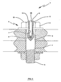
Fig. 1 is a partly sectioned elevational view of the present invention showing the modifications to a fastener and the measuring element embodied into it for measuring the gap. Also shown is the portable reactance capacitor head with a ring type reactance capacitor and a cylindrical type reactance capacitor. The ring type reactance capacitor measures the gap between the face of the ring type reactance capacitor and the fixed part of the fastener. The cylindrical type reactance capacitor measures the gap between the face of cylindrical type reactance and the upper free end of the measuring element. The non-contact gap measuring device computes the difference between the free end of the measuring element and the datum plane (reference). The non-contact gap measuring device computes the difference between the two measurements, and the result is accurately calibrated to indicate clamping load generated by the fastener when it is in use. -
Fig. 2 is a view similar toFig. 1 showing the fastener described inFig. 1 without the portable head. -
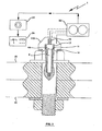
Fig. 3 is a view similar toFig. 1 showing an alternative option for measuring the gap by using only a cylindrical type reactance capacitor. The portable head is secured to the fixed part of the fastener datum face. The cylindrical type reactance capacitor measures the gap between the face of the cylindrical type reactance and the upper free end of the surface of the measuring element. The non-contact gap measuring device computes the different measurement of the gap and is calibrated to indicate clamping load induced by the fastener when it is in use. -
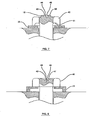
Fig. 4 is a view similar toFig. 1 showing a specially designed washer that deflects when the fastener system is under strain and an non-contact gap measuring device for measuring the gap. The reactance capacitor non-contact gap measuring device, when secured to the bolted joint, measures the gap between the face of the reactance capacitor and the part being measured on the washer. -
Fig. 5 is a view similar toFig. 1 showing a specially designed washer that deforms the head of the fastener so that two different parts of the head can be measured relative to each other by the reactance capacitor non-contact gap measuring device when the fastener is under strain. -
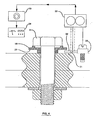
Fig. 6 is a view similar toFig. 1 showing a further modified form with an image processing or laser type gap measuring device fitted for use. -
Fig. 7 is a view similar toFig. 1 showing a fastener head which is modified to deflect under load when the fastener is subjected to a tensile force. -
Fig. 8 is a view similar toFig. 1 showing a further modification having a specially designed washer that deflects and also deflects the fastener head under load when the fastener is subjected to a tensile force. -
Fig. 9 is a view similar toFig. 1 showing a further modification in which the specially designed washer ofFig. 9 deflects under load when the fastener is subjected to a tensile force and the change in the gap is measured from the side of the system. - Referring now to the drawings in detail, as in
Figs. 1 ,2 , there is shown an embodiment of a load indicating fastener in bolted joint 25 in which in order to measure the changing gap between the faces of thereactance capacitors shank 4, there is provided abolt fastener system 1 having ametal body 2 made from steel, for example, which includes ahexagon head 3 and ashank 4, theshank 4 having an externally screw-threadedportion 5 spaced from thehead 3 by a plaincylindrical portion 6,washers nut 28, and areactance capacitor 15A which, in theFig. 1 embodiment, includes thecylindrical reactance capacitor 15 and thering reactance capacitor 16 for measuring the changing gap. - Drilled into the
body 2, co-axially with its rotational axis, is ablind bore 7 which extends from the top of thehead 3, through thehead 3 and into theshank 4 for approximately a quarter the length of the plaincylindrical portion 6. The closed inner end of thebore 7 is a close tolerancesmaller counterbore 9, which serves as an anchor for measuringelement 8. - Supported in the
bore 7 is a load sensing means, which comprises the measuringelement 8, made from the same material as thebody 2. Theelement 8 is anchored in thebore 7 atcounterbore 9. The anchorage could, for example, be pressed intobore 9 or may be secured therein by any of various types of fixing. - The upper surface of
head 3 is machined to form alocation spigot 10,upper datum face 11 and alower face 12. Theelement 8free end 8A is ground flush with thehead 3upper datum face 11. Theelement 8 responds to loads applied to theshank 4 bynut 28 when the fastener is in use. The response is related to the extension of theshank 4 under applied loads. - It is appropriate for the
element 8 to sense applied loads and to indicate said loads up to the proof load for the material of thebody 2. Therefore, theelement 8 is arranged to respond to the extension of theshank 4 up to the extension caused by the proof load. For this to be achieved theelement 8 is set inbore 7 of the body such that the anchorage incounterbore 9 moves theelement 8 into or out of thebody 2 depending on the load being induced into theshank 4. Therefore, theelement 8free end 8A moves relative to thehead 3upper datum surface 11 depending upon whether theshank 4 is being loaded or unloaded. When theshank 4 is free from load, theelement 8 and the headupper datum surface 11 are flush which indicates no load in theshank 4. Because theshank 4 material obeys Hookes Law, the gap created between theelement 8free end 8A and thehead 3upper datum surface 11 can be calibrated to indicate load by the portablehead measuring device 13 up to the proof load of theshank 4 materials. Provided the proof load is not exceeded, the load indication will be always repeatable. - The
portable head 13 carries thereactance capacitors head 3locating spigot 10. Theportable head 13 is secured to thehead 3 by amagnet 14 mounted on the bottom ofportable head 13, orportable head 13 may be secured tohead 3 by other known means. The ringtype reactance capacitor 16 measures the gap between the face 11B of thecapacitor 16 and thehead 3upper datum surface 11. The cylindricaltype reactance capacitor 15 measures the gap between the surface 11A of thecapacitor 15 and thefree end 8A ofelement 8. The said gaps between the said surfaces and the twocapacitors reactance capacitors capacitance amplifier 22,signal conditioner 23, anddisplay 24 and which are calibrated to indicate load that theshank 4 is subjected to during its use. - The ring
type reactance capacitor 16 ofFig. 1 is replaced inFig. 3 by asolid metal disc 17 which is mounted inportable head 17A and which abuts thehead 3upper datum face 11. - The
reactance capacitor 15 still operates in the same way as described forFig. 1 . All other details are as described forFig. 1 . Thereactance capacitor 15 compares the difference between thedatum surface 11 and the movement ofelement 8 when the system is in use. - As shown in
Fig. 4 , thefastener system 1 deflectswasher 18 when it is in use. Thereactance capacitor 31 measures the gap between theface 32 of thecapacitor 31 and thewasher 18surface 20. The system operates as described forFig. 1 . - Shown in
Fig. 5 is specially designedwasher 21 which deflects thehead 3 of the bolt and thering reactance capacitors portable head 33A and located atop thebolt head 3 bylocation peg 33, compare two parts of thehead 3 relative to each other to indicate load. Otherwise the system is as described forFig. 1 . - As seen in
Fig. 6 , theportable head 34A carries the camera orlaser 34 which is connected to imageprocessor 35 which is connected toreadout 36.Portable head 34A is constructed to accurately locate onto thehead 3locating spigot 10. Theportable head 34A is secured to thehead 3 by amagnet 14 mounted on the bottom ofportable head 34A, orportable head 34A may be secured tohead 3 by other known means. The camera orlaser system free end face 8A of theelement 8 and theupper datum surface 11 ofhead 3. The gaps between thedatum surface 11 and thefree end 8A of theelement 8 are compared by the camera orlaser system shank 4 is subjected to during its use. Thecamera 34 can be replaced by alaser 34 and coupled to aprocessor 35 and to areadout 36 or to a computer (not shown). - As seen in
Fig. 7 an alternative option for measuring thefastener head 40 deflection when the system is under load. The specially designedhead 40 is shaped with anannular groove 41, aspigot 10 having an annularouter face 42 surrounding arecess 43 having afloor 44 andcylindrical wall 45, and theportable monitor 34A with the camera orlaser 34 detects the change in shape of the head when under load. The electronics is calibrated to recognize the load scale from zero to proof load of the material and indicates load induced into the fastener. -
Fig. 8 is the same as that described inFig. 7 , but aspecial washer 21 causes the specially designedhead 46, havingrecess 43 withfloor 44 andwall 45 and outboardconcave face 47, to deflect. -
Fig. 9 is the same as that described inFig. 7 , but thespecial washer 22 changing shape due to the fastener system loading up to the material's proof load is detected by either the camera orlaser 34 as shown. - The foregoing description of a preferred embodiment and best mode of the invention known to applicant at the time of filing the application has been presented for the purposes of illustration and description. It is not intended to be exhaustive or to limit the invention to the precise form disclosed, and obviously many modifications and variations are possible in the light of the above teaching. The embodiment was chosen and described in order to best explain the principles of the invention and its practical application to thereby enable others skilled in the art to best utilize the invention in various embodiments and with various modifications as are suited to the particular use contemplated. It is intended that the scope of the invention be defined by the claims appended hereto.
Claims (2)
- Apparatus comprising:a fastener (1) including a bolt head (3), having a datum face (11), and a shank (4), a bore (7) extending into the fastener (1) through the bolt head (3) and into the shank (4), a bar (8) disposed in the bore (7) and secured to the fastener (1) and having an end face (8A) located near the datum face (11), and a changing gap that forms between the end face (8A) of the bar (8) and the datum face (11) of the bolt head (3) in response to load applied to the fastener (1); characterized in that the apparatus further comprisesa reactance capacitor supported by a portable sensing head (13,17A,33A) removably carried atop the bolt head (3) in a circuit for detecting the changing gap causing a variance in a capacitive reactance of the circuit without contacting the end face (8A) or the datum face (11).
- Apparatus according to claim 1, wherein the reactance capacitor in the circuit is formed by two reactance capacitors (15 and 16).
Applications Claiming Priority (3)
| Application Number | Priority Date | Filing Date | Title |
|---|---|---|---|
| GBGB9717566.5A GB9717566D0 (en) | 1997-08-19 | 1997-08-19 | Load indicating fastener systems |
| GBGB9718332.1A GB9718332D0 (en) | 1997-09-01 | 1997-09-01 | Load indicating fastener system |
| EP98940956A EP1003978B1 (en) | 1997-08-19 | 1998-08-17 | Load indicating fastener systems method and apparatus |
Related Parent Applications (1)
| Application Number | Title | Priority Date | Filing Date |
|---|---|---|---|
| EP98940956.0 Division | 1998-08-17 |
Publications (2)
| Publication Number | Publication Date |
|---|---|
| EP2175147A1 EP2175147A1 (en) | 2010-04-14 |
| EP2175147B1 true EP2175147B1 (en) | 2011-10-19 |
Family
ID=26312090
Family Applications (2)
| Application Number | Title | Priority Date | Filing Date |
|---|---|---|---|
| EP98940956A Expired - Lifetime EP1003978B1 (en) | 1997-08-19 | 1998-08-17 | Load indicating fastener systems method and apparatus |
| EP09015749A Expired - Lifetime EP2175147B1 (en) | 1997-08-19 | 1998-08-17 | Load indicating fastener apparatus |
Family Applications Before (1)
| Application Number | Title | Priority Date | Filing Date |
|---|---|---|---|
| EP98940956A Expired - Lifetime EP1003978B1 (en) | 1997-08-19 | 1998-08-17 | Load indicating fastener systems method and apparatus |
Country Status (16)
| Country | Link |
|---|---|
| EP (2) | EP1003978B1 (en) |
| JP (3) | JP2001515218A (en) |
| KR (1) | KR100411354B1 (en) |
| CN (1) | CN1146721C (en) |
| AT (2) | ATE453057T1 (en) |
| AU (1) | AU743407B2 (en) |
| BR (1) | BR9812129A (en) |
| CA (1) | CA2300894C (en) |
| DE (1) | DE69841403D1 (en) |
| DK (2) | DK2175147T3 (en) |
| EA (1) | EA001307B1 (en) |
| ES (2) | ES2338726T3 (en) |
| ID (1) | ID29459A (en) |
| NO (1) | NO330778B1 (en) |
| PT (1) | PT1003978E (en) |
| WO (1) | WO1999009327A1 (en) |
Families Citing this family (30)
| Publication number | Priority date | Publication date | Assignee | Title |
|---|---|---|---|---|
| CZ293517B6 (en) | 1999-06-22 | 2004-05-12 | Škodaáautoźáa@Ás | Attachment bolt for repeated tightening in excess of yield value |
| GB2372826A (en) * | 2001-03-01 | 2002-09-04 | Rotabolt Ltd | Load-indicating fastener |
| EP1254865A1 (en) | 2001-04-27 | 2002-11-06 | VA TECH WABAG GmbH | Disintegration of Anaerobically digested sewage sludge |
| GB0121317D0 (en) * | 2001-09-03 | 2001-10-24 | Sjb Engineering Ltd | Load-indicating fastener |
| KR100507982B1 (en) * | 2002-11-18 | 2005-08-17 | 주식회사 포스코 | Air pressing type shear pin cut detector |
| US7289033B2 (en) * | 2005-06-30 | 2007-10-30 | General Electric Co. | Wireless sensing washers for imaging device attachment |
| NL1033069C2 (en) * | 2006-12-15 | 2008-06-17 | Ind Bolting Technology And Sup | Device and method for tightening a nut turned on a threaded end and composite washer and nut for such a device. |
| GB2469019A (en) * | 2009-03-30 | 2010-10-06 | Ronald Scott | Bolt pre-load monitor using eddy current displacement sensor |
| US8659307B2 (en) * | 2010-08-17 | 2014-02-25 | Rosemount Aerospace Inc. | Capacitive sensors for monitoring load bearing on pins |
| CN101886961B (en) * | 2010-07-26 | 2011-11-16 | 西安理工大学 | Full-load static characteristic test device and test method of bolt joint surface unit |
| DE102010042263A1 (en) * | 2010-10-11 | 2012-04-12 | Hilti Aktiengesellschaft | Sensor arrangement, for example on an anchor bolt |
| US10131419B2 (en) | 2010-10-15 | 2018-11-20 | Goodrich Corporation | Systems and methods for detecting landing gear ground loads |
| JP5738053B2 (en) * | 2011-04-18 | 2015-06-17 | 株式会社ニフコ | Fastener |
| GB201115040D0 (en) * | 2011-08-31 | 2011-10-12 | Phipps Maria J | Load indicating washer |
| CN103164997A (en) * | 2011-12-13 | 2013-06-19 | 南京梅山冶金发展有限公司 | Bolt fastening practical training device |
| GB201300093D0 (en) * | 2013-01-04 | 2013-02-20 | Phipps Maria J | Load indicating nut/washer |
| US10316881B2 (en) | 2014-07-30 | 2019-06-11 | Integrity Engineering Solutions Pty Ltd | Fasteners |
| KR101843041B1 (en) * | 2016-03-16 | 2018-03-29 | 충남대학교산학협력단 | Displacement Measure Apparatus for Fixing part of Fastener |
| AU2017268037B2 (en) * | 2016-05-18 | 2023-02-02 | Integrity Engineering Solutions Pty Ltd | A load indicating fastener |
| CN106323154B (en) * | 2016-08-12 | 2019-08-02 | 安徽容知日新科技股份有限公司 | Monitor the apparatus and system that fastener loosens |
| CN106054263A (en) * | 2016-08-22 | 2016-10-26 | 杨志强 | Screw loosening monitoring device and system |
| DE102016012564A1 (en) * | 2016-10-21 | 2018-04-26 | GLBS Patentverwertungsgesellschaft GbR (vertretungsber. Gesellschafter Dr. Jörg Stahlmann, 64546 Mörfelden-Walldorf und Dr. Matthias Brenneis, 63776 Mömbris) | Connecting element with integrated sensor |
| CN107505077A (en) * | 2017-06-30 | 2017-12-22 | 上海应谱科技有限公司 | A kind of measuring method of the pretightning force of intelligent fastener |
| CN107339309A (en) * | 2017-06-30 | 2017-11-10 | 上海应谱科技有限公司 | A kind of pretightning force monitoring system of intelligent fastener |
| CN108571504A (en) * | 2018-05-08 | 2018-09-25 | 上海威纳工程技术有限公司 | Accurate pretension bolt |
| JP7427220B2 (en) * | 2019-11-28 | 2024-02-05 | Fsテクニカル株式会社 | Load sensing device, metal anchor, network system, anchor system, and control method for load sensing device |
| GB202015203D0 (en) | 2020-09-25 | 2020-11-11 | Salunda Ltd | Integrated fastener assembly sensor unit |
| CN113035034B (en) * | 2021-03-11 | 2022-11-18 | 湖州师范学院 | Overlapped type high-stability adjustable double-slit device |
| CN113959624A (en) * | 2021-09-29 | 2022-01-21 | 嘉兴博感科技有限公司 | A smart device for sensing force and smart bolt or smart nut |
| CN114113305B (en) * | 2021-09-29 | 2023-06-16 | 华电电力科学研究院有限公司 | Device and method for detecting bolt holes of steam turbine cylinder body of thermal power plant |
Family Cites Families (21)
| Publication number | Priority date | Publication date | Assignee | Title |
|---|---|---|---|---|
| US30183A (en) * | 1860-09-25 | putney | ||
| JPS4951281U (en) * | 1972-08-09 | 1974-05-07 | ||
| US3886840A (en) * | 1972-10-24 | 1975-06-03 | Kaman Aerospace Corp | Bolt head which measures and maintains preload |
| USRE30183E (en) | 1976-09-24 | 1980-01-08 | Radio-frequency tuned-circuit microdisplacement transducer | |
| US4294122A (en) * | 1979-07-12 | 1981-10-13 | General Dynamics Corporation | Fastener incorporating ultrasonic transducer |
| JPS57121407U (en) * | 1981-01-23 | 1982-07-28 | ||
| US4581712A (en) * | 1982-11-10 | 1986-04-08 | Perry Huey J | Roof pressure monitoring system |
| JPH074484Y2 (en) * | 1983-01-29 | 1995-02-01 | 川崎重工業株式会社 | Tightening bolt |
| US4846001A (en) * | 1987-09-11 | 1989-07-11 | Sps Technologies, Inc. | Ultrasonic load indicating member |
| US4899591A (en) * | 1987-09-11 | 1990-02-13 | Sps Technologies, Inc. | Ultrasonic load indicating member, apparatus and method |
| JPH0174030U (en) * | 1987-11-05 | 1989-05-18 | ||
| GB8726339D0 (en) * | 1987-11-10 | 1987-12-16 | Walton B | Fastener |
| US5291789A (en) * | 1987-11-10 | 1994-03-08 | Rotabolt Limited | Load indicating |
| JPH0663890B2 (en) * | 1988-03-16 | 1994-08-22 | 伸二 清水 | Axial force sensor for bolts with holes |
| JPH0478315U (en) * | 1990-11-20 | 1992-07-08 | ||
| GB2251908B (en) * | 1991-01-16 | 1993-12-15 | Rotabolt Ltd | Load indicating |
| SE9102122D0 (en) * | 1991-07-08 | 1991-07-08 | Skf Nova Ab | SENSOR RESPECTIVE PROCEDURE BEFORE SEATING TORQUE AND / OR FORCES |
| AU664186B2 (en) * | 1991-08-30 | 1995-11-09 | Technological Resources Pty Limited | Rock bolt load sensor |
| DE4410722A1 (en) * | 1994-03-28 | 1995-10-05 | Bosch Gmbh Robert | Non-contact bolt tightening force measurement appts. for quality control |
| DE4419009A1 (en) * | 1994-05-31 | 1995-12-21 | Juergen Blumenauer | Compressive force measuring system for vehicle wheelnuts etc. |
| US5691815A (en) * | 1996-01-02 | 1997-11-25 | Lockheed Missiles & Space Co., Inc. | Laser inspection tool system |
-
1998
- 1998-08-17 DK DK09015749.6T patent/DK2175147T3/en active
- 1998-08-17 ES ES98940956T patent/ES2338726T3/en not_active Expired - Lifetime
- 1998-08-17 ES ES09015749T patent/ES2375090T3/en not_active Expired - Lifetime
- 1998-08-17 ID IDW20000476D patent/ID29459A/en unknown
- 1998-08-17 AU AU89115/98A patent/AU743407B2/en not_active Expired
- 1998-08-17 PT PT98940956T patent/PT1003978E/en unknown
- 1998-08-17 KR KR10-2000-7001696A patent/KR100411354B1/en not_active Expired - Lifetime
- 1998-08-17 AT AT98940956T patent/ATE453057T1/en active
- 1998-08-17 CN CNB988082586A patent/CN1146721C/en not_active Expired - Lifetime
- 1998-08-17 BR BR9812129-4A patent/BR9812129A/en not_active IP Right Cessation
- 1998-08-17 EP EP98940956A patent/EP1003978B1/en not_active Expired - Lifetime
- 1998-08-17 DE DE69841403T patent/DE69841403D1/en not_active Expired - Lifetime
- 1998-08-17 AT AT09015749T patent/ATE529646T1/en not_active IP Right Cessation
- 1998-08-17 WO PCT/US1998/017060 patent/WO1999009327A1/en not_active Ceased
- 1998-08-17 EP EP09015749A patent/EP2175147B1/en not_active Expired - Lifetime
- 1998-08-17 DK DK98940956.0T patent/DK1003978T3/en active
- 1998-08-17 EA EA200000217A patent/EA001307B1/en not_active IP Right Cessation
- 1998-08-17 CA CA002300894A patent/CA2300894C/en not_active Expired - Fee Related
- 1998-08-17 JP JP2000509958A patent/JP2001515218A/en active Pending
-
2000
- 2000-02-18 NO NO20000824A patent/NO330778B1/en not_active IP Right Cessation
-
2003
- 2003-06-05 JP JP2003161053A patent/JP2003329525A/en active Pending
-
2007
- 2007-09-21 JP JP2007245508A patent/JP2008058321A/en active Pending
Also Published As
| Publication number | Publication date |
|---|---|
| CN1146721C (en) | 2004-04-21 |
| WO1999009327A1 (en) | 1999-02-25 |
| EP1003978A1 (en) | 2000-05-31 |
| JP2008058321A (en) | 2008-03-13 |
| JP2003329525A (en) | 2003-11-19 |
| ES2338726T3 (en) | 2010-05-11 |
| DK2175147T3 (en) | 2012-02-06 |
| EA200000217A1 (en) | 2000-10-30 |
| AU8911598A (en) | 1999-03-08 |
| DK1003978T3 (en) | 2010-04-26 |
| EP1003978A4 (en) | 2007-05-30 |
| BR9812129A (en) | 2000-07-18 |
| CA2300894C (en) | 2006-06-06 |
| ID29459A (en) | 2001-08-30 |
| ATE529646T1 (en) | 2011-11-15 |
| KR100411354B1 (en) | 2003-12-24 |
| NO20000824D0 (en) | 2000-02-18 |
| KR20010023077A (en) | 2001-03-26 |
| CA2300894A1 (en) | 1999-02-25 |
| CN1267362A (en) | 2000-09-20 |
| ES2375090T3 (en) | 2012-02-24 |
| NO330778B1 (en) | 2011-07-11 |
| EP1003978B1 (en) | 2009-12-23 |
| AU743407B2 (en) | 2002-01-24 |
| PT1003978E (en) | 2010-03-12 |
| JP2001515218A (en) | 2001-09-18 |
| NO20000824L (en) | 2000-04-14 |
| EA001307B1 (en) | 2000-12-25 |
| DE69841403D1 (en) | 2010-02-04 |
| ATE453057T1 (en) | 2010-01-15 |
| EP2175147A1 (en) | 2010-04-14 |
Similar Documents
| Publication | Publication Date | Title |
|---|---|---|
| EP2175147B1 (en) | Load indicating fastener apparatus | |
| US6204771B1 (en) | Load indicating fastener systems method and apparatus | |
| US5392654A (en) | Rock bolt load sensor | |
| US9483674B1 (en) | RFID torque sensing tag system for fasteners | |
| US4429579A (en) | Tie rod tension sensor | |
| EP0441145B1 (en) | Ultrasonic load indicating member | |
| US8869633B2 (en) | Bearing device having a sensor for measuring the vertical bearing force of a rotating shaft | |
| JP2944315B2 (en) | Preload detection device | |
| US5569866A (en) | Force measuring device | |
| US5734110A (en) | Temperature compensated, easily installed bolt-on strain sensor | |
| US6832881B2 (en) | Connecting element | |
| US11536618B2 (en) | External tie-rod load indicator | |
| EP3483577B1 (en) | System and method for determining tension of a non-living object | |
| WO2000022306A1 (en) | Monitoring tension of threaded fasteners | |
| MXPA00001636A (en) | Load indicating fastener systems method and apparatus | |
| RU2786759C1 (en) | Strain sensor | |
| EP4495565A1 (en) | Sensorized mechanical coupling device | |
| Mekid | Tension monitoring devices development for bolted joints | |
| Fink et al. | RFID Torque Sensing Tag System for Fasteners | |
| US20250172446A1 (en) | Force sensor having contact member and annular force sensing device including the same | |
| KR20000056288A (en) | Device measuring bolt force of plastic region tightening bolt | |
| AU2004200078A1 (en) | Monitoring Tension of Threaded Fasteners | |
| US20240319028A1 (en) | Method for Ascertaining a Force and/or Torque acting on a Component, Sensor Arrangement, and Use thereof | |
| AU1020100A (en) | Monitoring tension of threaded fasteners | |
| AU2006203211A1 (en) | Monitoring Tension of Threaded Fasteners |
Legal Events
| Date | Code | Title | Description |
|---|---|---|---|
| PUAI | Public reference made under article 153(3) epc to a published international application that has entered the european phase |
Free format text: ORIGINAL CODE: 0009012 |
|
| 17P | Request for examination filed |
Effective date: 20091218 |
|
| AC | Divisional application: reference to earlier application |
Ref document number: 1003978 Country of ref document: EP Kind code of ref document: P |
|
| AK | Designated contracting states |
Kind code of ref document: A1 Designated state(s): AT BE CH CY DE DK ES FI FR GB GR IE IT LI LU MC NL PT SE |
|
| AX | Request for extension of the european patent |
Extension state: RO |
|
| 17Q | First examination report despatched |
Effective date: 20100722 |
|
| RIC1 | Information provided on ipc code assigned before grant |
Ipc: H01F 5/00 20060101ALI20110217BHEP Ipc: G01N 27/00 20060101ALI20110217BHEP Ipc: F16B 31/02 20060101AFI20110217BHEP Ipc: G01B 7/16 20060101ALI20110217BHEP Ipc: G01N 21/00 20060101ALI20110217BHEP |
|
| GRAP | Despatch of communication of intention to grant a patent |
Free format text: ORIGINAL CODE: EPIDOSNIGR1 |
|
| RTI1 | Title (correction) |
Free format text: LOAD INDICATING FASTENER APPARATUS |
|
| GRAS | Grant fee paid |
Free format text: ORIGINAL CODE: EPIDOSNIGR3 |
|
| GRAA | (expected) grant |
Free format text: ORIGINAL CODE: 0009210 |
|
| AC | Divisional application: reference to earlier application |
Ref document number: 1003978 Country of ref document: EP Kind code of ref document: P |
|
| AK | Designated contracting states |
Kind code of ref document: B1 Designated state(s): AT BE CH CY DE DK ES FI FR GB GR IE IT LI LU MC NL PT SE |
|
| REG | Reference to a national code |
Ref country code: GB Ref legal event code: FG4D |
|
| REG | Reference to a national code |
Ref country code: CH Ref legal event code: EP |
|
| REG | Reference to a national code |
Ref country code: IE Ref legal event code: FG4D |
|
| REG | Reference to a national code |
Ref country code: DE Ref legal event code: R096 Ref document number: 69842461 Country of ref document: DE Effective date: 20111215 |
|
| REG | Reference to a national code |
Ref country code: SE Ref legal event code: TRGR |
|
| REG | Reference to a national code |
Ref country code: DK Ref legal event code: T3 |
|
| REG | Reference to a national code |
Ref country code: NL Ref legal event code: VDEP Effective date: 20111019 |
|
| REG | Reference to a national code |
Ref country code: ES Ref legal event code: FG2A Ref document number: 2375090 Country of ref document: ES Kind code of ref document: T3 Effective date: 20120224 |
|
| REG | Reference to a national code |
Ref country code: AT Ref legal event code: MK05 Ref document number: 529646 Country of ref document: AT Kind code of ref document: T Effective date: 20111019 |
|
| PG25 | Lapsed in a contracting state [announced via postgrant information from national office to epo] |
Ref country code: BE Free format text: LAPSE BECAUSE OF FAILURE TO SUBMIT A TRANSLATION OF THE DESCRIPTION OR TO PAY THE FEE WITHIN THE PRESCRIBED TIME-LIMIT Effective date: 20111019 |
|
| PG25 | Lapsed in a contracting state [announced via postgrant information from national office to epo] |
Ref country code: GR Free format text: LAPSE BECAUSE OF FAILURE TO SUBMIT A TRANSLATION OF THE DESCRIPTION OR TO PAY THE FEE WITHIN THE PRESCRIBED TIME-LIMIT Effective date: 20120120 Ref country code: NL Free format text: LAPSE BECAUSE OF FAILURE TO SUBMIT A TRANSLATION OF THE DESCRIPTION OR TO PAY THE FEE WITHIN THE PRESCRIBED TIME-LIMIT Effective date: 20111019 Ref country code: PT Free format text: LAPSE BECAUSE OF FAILURE TO SUBMIT A TRANSLATION OF THE DESCRIPTION OR TO PAY THE FEE WITHIN THE PRESCRIBED TIME-LIMIT Effective date: 20120220 |
|
| PG25 | Lapsed in a contracting state [announced via postgrant information from national office to epo] |
Ref country code: CY Free format text: LAPSE BECAUSE OF FAILURE TO SUBMIT A TRANSLATION OF THE DESCRIPTION OR TO PAY THE FEE WITHIN THE PRESCRIBED TIME-LIMIT Effective date: 20111019 |
|
| PLBE | No opposition filed within time limit |
Free format text: ORIGINAL CODE: 0009261 |
|
| STAA | Information on the status of an ep patent application or granted ep patent |
Free format text: STATUS: NO OPPOSITION FILED WITHIN TIME LIMIT |
|
| PG25 | Lapsed in a contracting state [announced via postgrant information from national office to epo] |
Ref country code: IT Free format text: LAPSE BECAUSE OF FAILURE TO SUBMIT A TRANSLATION OF THE DESCRIPTION OR TO PAY THE FEE WITHIN THE PRESCRIBED TIME-LIMIT Effective date: 20111019 |
|
| 26N | No opposition filed |
Effective date: 20120720 |
|
| REG | Reference to a national code |
Ref country code: DE Ref legal event code: R097 Ref document number: 69842461 Country of ref document: DE Effective date: 20120720 |
|
| PG25 | Lapsed in a contracting state [announced via postgrant information from national office to epo] |
Ref country code: AT Free format text: LAPSE BECAUSE OF FAILURE TO SUBMIT A TRANSLATION OF THE DESCRIPTION OR TO PAY THE FEE WITHIN THE PRESCRIBED TIME-LIMIT Effective date: 20111019 |
|
| REG | Reference to a national code |
Ref country code: CH Ref legal event code: PL |
|
| PG25 | Lapsed in a contracting state [announced via postgrant information from national office to epo] |
Ref country code: MC Free format text: LAPSE BECAUSE OF NON-PAYMENT OF DUE FEES Effective date: 20120831 |
|
| PG25 | Lapsed in a contracting state [announced via postgrant information from national office to epo] |
Ref country code: CH Free format text: LAPSE BECAUSE OF NON-PAYMENT OF DUE FEES Effective date: 20120831 Ref country code: LI Free format text: LAPSE BECAUSE OF NON-PAYMENT OF DUE FEES Effective date: 20120831 |
|
| REG | Reference to a national code |
Ref country code: FR Ref legal event code: ST Effective date: 20130430 |
|
| REG | Reference to a national code |
Ref country code: IE Ref legal event code: MM4A |
|
| PG25 | Lapsed in a contracting state [announced via postgrant information from national office to epo] |
Ref country code: FI Free format text: LAPSE BECAUSE OF FAILURE TO SUBMIT A TRANSLATION OF THE DESCRIPTION OR TO PAY THE FEE WITHIN THE PRESCRIBED TIME-LIMIT Effective date: 20111019 |
|
| PG25 | Lapsed in a contracting state [announced via postgrant information from national office to epo] |
Ref country code: IE Free format text: LAPSE BECAUSE OF NON-PAYMENT OF DUE FEES Effective date: 20120817 |
|
| PG25 | Lapsed in a contracting state [announced via postgrant information from national office to epo] |
Ref country code: FR Free format text: LAPSE BECAUSE OF NON-PAYMENT OF DUE FEES Effective date: 20120831 |
|
| REG | Reference to a national code |
Ref country code: CH Ref legal event code: NV Representative=s name: CRONIN INTELLECTUAL PROPERTY, CH Ref country code: CH Ref legal event code: AECN Free format text: DAS PATENT IST AUFGRUND DES WEITERBEHANDLUNGSANTRAGS VOM 24.05.2013 REAKTIVIERT WORDEN. |
|
| PGRI | Patent reinstated in contracting state [announced from national office to epo] |
Ref country code: CH Effective date: 20130822 Ref country code: LI Effective date: 20130822 |
|
| REG | Reference to a national code |
Ref country code: DE Ref legal event code: R082 Ref document number: 69842461 Country of ref document: DE Representative=s name: BOCKHORNI & KOLLEGEN PATENT- UND RECHTSANWAELT, DE Ref country code: DE Ref legal event code: R082 Ref document number: 69842461 Country of ref document: DE Representative=s name: HEYER, VOLKER, DIPL.-PHYS. DR.RER.NAT., DE |
|
| REG | Reference to a national code |
Ref country code: DE Ref legal event code: R082 Ref document number: 69842461 Country of ref document: DE Representative=s name: HEYER, VOLKER, DIPL.-PHYS. DR.RER.NAT., DE |
|
| PG25 | Lapsed in a contracting state [announced via postgrant information from national office to epo] |
Ref country code: LU Free format text: LAPSE BECAUSE OF NON-PAYMENT OF DUE FEES Effective date: 20120817 |
|
| PGFP | Annual fee paid to national office [announced via postgrant information from national office to epo] |
Ref country code: CH Payment date: 20160829 Year of fee payment: 19 Ref country code: DK Payment date: 20160831 Year of fee payment: 19 |
|
| PGFP | Annual fee paid to national office [announced via postgrant information from national office to epo] |
Ref country code: SE Payment date: 20160829 Year of fee payment: 19 |
|
| PGFP | Annual fee paid to national office [announced via postgrant information from national office to epo] |
Ref country code: ES Payment date: 20160826 Year of fee payment: 19 |
|
| PGFP | Annual fee paid to national office [announced via postgrant information from national office to epo] |
Ref country code: GB Payment date: 20170829 Year of fee payment: 20 Ref country code: DE Payment date: 20170829 Year of fee payment: 20 |
|
| REG | Reference to a national code |
Ref country code: DK Ref legal event code: EBP Effective date: 20170831 |
|
| REG | Reference to a national code |
Ref country code: CH Ref legal event code: PL |
|
| PG25 | Lapsed in a contracting state [announced via postgrant information from national office to epo] |
Ref country code: SE Free format text: LAPSE BECAUSE OF NON-PAYMENT OF DUE FEES Effective date: 20170818 Ref country code: CH Free format text: LAPSE BECAUSE OF NON-PAYMENT OF DUE FEES Effective date: 20170831 Ref country code: LI Free format text: LAPSE BECAUSE OF NON-PAYMENT OF DUE FEES Effective date: 20170831 |
|
| PG25 | Lapsed in a contracting state [announced via postgrant information from national office to epo] |
Ref country code: DK Free format text: LAPSE BECAUSE OF NON-PAYMENT OF DUE FEES Effective date: 20170831 |
|
| REG | Reference to a national code |
Ref country code: DE Ref legal event code: R071 Ref document number: 69842461 Country of ref document: DE |
|
| REG | Reference to a national code |
Ref country code: GB Ref legal event code: PE20 Expiry date: 20180816 |
|
| REG | Reference to a national code |
Ref country code: ES Ref legal event code: FD2A Effective date: 20181024 |
|
| REG | Reference to a national code |
Ref country code: ES Ref legal event code: FD2A Effective date: 20181025 |
|
| PG25 | Lapsed in a contracting state [announced via postgrant information from national office to epo] |
Ref country code: GB Free format text: LAPSE BECAUSE OF EXPIRATION OF PROTECTION Effective date: 20180816 |
|
| PG25 | Lapsed in a contracting state [announced via postgrant information from national office to epo] |
Ref country code: ES Free format text: LAPSE BECAUSE OF NON-PAYMENT OF DUE FEES Effective date: 20170818 |