EP2175145A1 - Feststell- und Verbindungsvorrichtung zur Befestigung der Stäbe von zwei verschiedenen Rahmen in einer reziproken Position - Google Patents
Feststell- und Verbindungsvorrichtung zur Befestigung der Stäbe von zwei verschiedenen Rahmen in einer reziproken Position Download PDFInfo
- Publication number
- EP2175145A1 EP2175145A1 EP08017718A EP08017718A EP2175145A1 EP 2175145 A1 EP2175145 A1 EP 2175145A1 EP 08017718 A EP08017718 A EP 08017718A EP 08017718 A EP08017718 A EP 08017718A EP 2175145 A1 EP2175145 A1 EP 2175145A1
- Authority
- EP
- European Patent Office
- Prior art keywords
- rods
- lock
- connection device
- frame
- reciprocal
- Prior art date
- Legal status (The legal status is an assumption and is not a legal conclusion. Google has not performed a legal analysis and makes no representation as to the accuracy of the status listed.)
- Granted
Links
Images


Classifications
-
- A—HUMAN NECESSITIES
- A47—FURNITURE; DOMESTIC ARTICLES OR APPLIANCES; COFFEE MILLS; SPICE MILLS; SUCTION CLEANERS IN GENERAL
- A47B—TABLES; DESKS; OFFICE FURNITURE; CABINETS; DRAWERS; GENERAL DETAILS OF FURNITURE
- A47B57/00—Cabinets, racks or shelf units, characterised by features for adjusting shelves or partitions
- A47B57/30—Cabinets, racks or shelf units, characterised by features for adjusting shelves or partitions with means for adjusting the height of detachable shelf supports
- A47B57/54—Cabinets, racks or shelf units, characterised by features for adjusting shelves or partitions with means for adjusting the height of detachable shelf supports consisting of clamping means, e.g. with sliding bolts or sliding wedges
-
- A—HUMAN NECESSITIES
- A47—FURNITURE; DOMESTIC ARTICLES OR APPLIANCES; COFFEE MILLS; SPICE MILLS; SUCTION CLEANERS IN GENERAL
- A47F—SPECIAL FURNITURE, FITTINGS, OR ACCESSORIES FOR SHOPS, STOREHOUSES, BARS, RESTAURANTS OR THE LIKE; PAYING COUNTERS
- A47F5/00—Show stands, hangers, or shelves characterised by their constructional features
- A47F5/14—Tubular connecting elements for wire stands
-
- F—MECHANICAL ENGINEERING; LIGHTING; HEATING; WEAPONS; BLASTING
- F16—ENGINEERING ELEMENTS AND UNITS; GENERAL MEASURES FOR PRODUCING AND MAINTAINING EFFECTIVE FUNCTIONING OF MACHINES OR INSTALLATIONS; THERMAL INSULATION IN GENERAL
- F16B—DEVICES FOR FASTENING OR SECURING CONSTRUCTIONAL ELEMENTS OR MACHINE PARTS TOGETHER, e.g. NAILS, BOLTS, CIRCLIPS, CLAMPS, CLIPS OR WEDGES; JOINTS OR JOINTING
- F16B12/00—Jointing of furniture or the like, e.g. hidden from exterior
- F16B12/40—Joints for furniture tubing
Definitions
- the present invention relates to a lock and connection device for fixing the rods of two distinct frames in a reciprocal position, chosen from a plurality of possible reciprocal positions, according to the preamble of claim 1.
- such elementary structures for placing objects are typically supported by a first frame which has a number of rods, which is connected to a second frame, also having a number of rods and which in turn is connected in a fixed way to the walls of the wardrobe compartment.
- the two frames are connected together, by means of the respective rods, in a reciprocally movable way, so that by moving them reciprocally, a plurality of possible reciprocal positions exist between the two frames.
- the assembly consisting of the two frames, to the respective different widths of the various compartments of the various wardrobes, which advantageously allows using these same two frames for a large number of different wardrobes which differ the one from the other in terms of the dimensions of their inner compartments.
- the Italian patent application nr. MO2004A000125 of the applicant shows a lock and connection device that allows fixing the rods of the first frame and the rods of the second frame in a determinate reciprocal position.
- the rods of the second frame accommodate the rods of the first frame sliding within them and the plurality of said reciprocal possible positions is given by all the intermediate positions together comprised between a first limit position corresponding to the situation of minimum length of the assembly made up of the two frames, in which the rods of the first frame are completely accommodated within the rods of the second frame, and a second limit position of maximum length of the assembly made up of the two frames, in which the rods of the first frame are accommodated, within the rods of the second frame, to the extent strictly necessary to make the connection between the two frames.
- Such a reciprocal position is fixed by means of stop screws, which prevent any further reciprocal movement.
- a typical example in this respect is, e.g., given by a supporting shelf for shoes, which is tilted to reduce the depth of the wardrobe that has to accommodate it.
- the aim behind the present invention is therefore to develop a lock and connection device for fixing the rods of two distinct frames in a reciprocal position which is an alternative to the known state of the art solution, as regards the movements, and which also allows, in addition to what it has been possible to do thus far, fixing the rods of the two frames in a reciprocal position even when these have been made to rotate reciprocally in a common plane.
- the claim 2 concerns an embodiment of the lock and connection device according to the invention, suitable in particular to the case in which the various reciprocal positions of the two frames are obtained by reciprocal movement.
- the specific operating capacity which is started by means of the reciprocal rotation of the two parts making up the lock and connection device according to the invention, is provided by the stretching apart of the two elastic fins which thus block and prevent any further reciprocal sliding between the rods of the two frames.
- the claim 6 concerns another embodiment of the lock and connection device according to the invention, suitable in particular for the case in which the various reciprocal positions of the two frames are obtained by reciprocal rotation.
- the specific operating capacity which is started by means of the reciprocal rotation of the two parts making up the lock and connection device according to the invention, is provided by the angular staggering which the first inner housings of the first part might have with respect to the second inner housings of the second part, angular staggering which permits, due to the fact that in the housings are the respective rods and thanks to the action of the envisaged coupling means, maintaining the rods of the two frames in reciprocal rotated position.
- a lock and connection device two embodiments of a lock and connection device have been indicated by 1a and 1b.
- the letters a or b refer to elements present in both embodiments, the letter a distinguishing the elements of the first embodiment and the letter b the elements of the second embodiment.
- this lock and connection device 1a; 1b is to fix in a reciprocal position, chosen from a plurality of possible reciprocal positions, the rods 2a, 3a; 2b, 3b of two distinct frames, specifically the rods 2a, 2b of a first frame and the rods 3a, 3b of a second frame.
- the first of these frames acts as a support for a structure for placing objects 4a; 4b while the second is connected, if necessary also indirectly, to the side walls of a wardrobe.
- the lock and connection device is in two parts 5a, 6a or 5b, 6b suitable for being reciprocally rotated by means of the manual action of a user.
- the reciprocal rotation of the two parts 5a, 6a or 5b, 6b determines the fixing of the rods 2a, 3a or 2b, 3b of the two frames in the reciprocal position in which they find themselves.
- the figures from 1 to 9 more specifically concern the first embodiment 1a of the lock and connection device according to the invention, suitable in particular for the case in which the rods 2a, 3a are in a reciprocal position obtained by accommodating the rods 3a of the second frame in the rods 2a of the first frame and making these reciprocally move.
- the rods 2a of the first frame the one that supports the elementary structures for placing the objects such as, e.g., those illustrated, a tray and a bar basket shown in an interrupted way.
- the rods 3a of the second frame the one connected to the walls of the wardrobe, e.g., as in the figure 1 to a structure not shown in detail connected in turn to the wardrobe, this not being represented either.
- the rods 3a can slide inside the rods 2a in the two directions indicated by the double arrow.
- the fixing in a reciprocal position is done by the first embodiment 1a of the lock and connection device, which in this figure has only been outlined inasmuch as it is located inside the rod 2a.
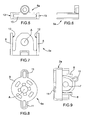
- the first part 5a shows a central body 7 and two elastic fins 8.
- the elastic fins 8 are arranged at the two sides of the central body 7 and are connected to this central body 7 at one of their extremities, as can be seen from the figure 7 .
- the second part 6a is on the other hand made up of a cam element 9, visible in particular in the figure 8 , which in fitted position is located between the two elastic fins 8 and is supported on the central body 7 in a rotating way with respect to the central body 7.
- the central body 7 opportunely has a substantially flat shape and a slot 10, within which is supported the cam element 9 which is opportunely in the shape of an oval disc having protruding appendices 11 jutting out from this.
- the figure 9 allows understanding in a particularly clear way the operation of this first embodiment 1a of the lock and connection device according to the invention. It is fitted in the rod 2a with the orientation drawn in the figure 4 .
- the user By acting manually on the second part 6a, i.e., on the cam element 9 or rather the oval disc and more precisely on its appendices 11, the user makes the second part 6a rotate with respect to the first part 5a, or to the central body 7.
- This rotation occurs around a rotation axis A, which is opportunely perpendicular to the main symmetry plane of the oval disc 9, and the contact between the second part 5a, i.e., the cam element 9, and the elastic fins 8, which occurs following said rotation, results in the fins 8 divaricating.
- the fins 8 come into contact with the rods 3a of the second frame and block these, preventing any further reciprocal sliding between the rods 2a and the rods 3a.
- the elastic fins 8 have, on the inside turned towards the slot 10, first longitudinal grooves 12, within which rolls the edge of the oval disc 9, and on the outside turned towards the rods 3a of the second frame second longitudinal grooves 13, by means of which, at the moment of divaricating, they adhere to the rods 3a of the second frame.
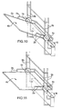
- the figures from 10 to 14 more specifically concern the second embodiment 1b of the lock and connection device according to the invention, suitable in particular in case the rods 2b, 3b are in a reciprocal position obtained by causing the rods 2b of the first frame to turn around a horizontal rotation axis B with respect to the rods 3b of the second frame.
- the rods 2b of the first frame to which is supported by way of example a supporting shelf 4b, e.g., for shoes.
- the rods 2b are turned at right angles in the figure 11 and at an acute angle in the figure 10 with respect to the rods 3b of the second frame, which is connected to a structure not represented in detail connected in turn to the wardrobe, this not shown either.
- the rods 3b can be rotated with respect to the rods 2b in the two directions indicated by the double curve arrow. Fixing in position is done by the second embodiment 1b of the lock and connection device, which in these figures 10 and 11 has only been outlined.
- the first part 5b has first inner housings 14 for the rods 2b of the first frame and the second part 6b has inner housings 15 for the rods 3b of the second frame.
- the two parts 5b, 6b are identical, as has been shown in the figure 13 .
- each of them can act indifferently both as first part 5b and second part 6b, as has been shown for example in the figure 12 , in which, when the part, which in the figure is on top, acts as first part 5b the inner housings it has act as first inner housings 14 and when it acts as second part 6b its inner housings act as second inner housings 15 and vice versa.
- first part 5b when the part, which in the figure is on top, acts as first part 5b the inner housings it has act as first inner housings 14 and when it acts as second part 6b its inner housings act as second inner housings 15 and vice versa.
- the same goes for the part which in the figure 12 is underneath.
- Coupling means are also envisaged, to join in a blocked way in a reciprocal position the two parts 5b, 6b. These coupling means are suitably-geometric coupling means.
- these coupling means are shown in the figure 13 .
- these are composed of a plurality of shaped elements 16 arranged on the inner side of the respective part 5b, 6b, among which 16 are free spaces 17 having the same shape as the shaped elements 16.
- the shaped elements 16 of a part 5b, 6b can fit into the free spaces 17 of the other part 6b, 5b and vice versa.
- the two parts 5b, 6b remain in position reciprocally rotated by effect of this reciprocal engagement between the shaped elements 16 of the two parts 5b, 6b.
- the shaped elements 16 and the free spaces 17 extend opportunely along radial lines, so as to create an overall structure with geometric coupling which is symmetric.
- the coupling means also comprise a stop screw 18, only outlined in the figures, which secures together the parts 5b, 6b after they have been joined.
- stop screw 18 is fitted that prevents the disengagement of the shaped elements 16 of the two parts 5b, 6b following a reciprocal removal movement along the direction of the axis B.
Landscapes
- Engineering & Computer Science (AREA)
- General Engineering & Computer Science (AREA)
- Mechanical Engineering (AREA)
- Mutual Connection Of Rods And Tubes (AREA)
- Furniture Connections (AREA)
Priority Applications (2)
| Application Number | Priority Date | Filing Date | Title |
|---|---|---|---|
| EP08017718A EP2175145B1 (de) | 2008-10-09 | 2008-10-09 | Feststell- und Verbindungsvorrichtung zur Befestigung der Stäbe von zwei verschiedenen Rahmen in einer reziproken Position |
| ES08017718T ES2419281T3 (es) | 2008-10-09 | 2008-10-09 | Dispositivo de conexión y trabado para fijar las varillas de dos bastidores distintos en una posición recíproca |
Applications Claiming Priority (1)
| Application Number | Priority Date | Filing Date | Title |
|---|---|---|---|
| EP08017718A EP2175145B1 (de) | 2008-10-09 | 2008-10-09 | Feststell- und Verbindungsvorrichtung zur Befestigung der Stäbe von zwei verschiedenen Rahmen in einer reziproken Position |
Publications (2)
| Publication Number | Publication Date |
|---|---|
| EP2175145A1 true EP2175145A1 (de) | 2010-04-14 |
| EP2175145B1 EP2175145B1 (de) | 2013-03-27 |
Family
ID=40380686
Family Applications (1)
| Application Number | Title | Priority Date | Filing Date |
|---|---|---|---|
| EP08017718A Active EP2175145B1 (de) | 2008-10-09 | 2008-10-09 | Feststell- und Verbindungsvorrichtung zur Befestigung der Stäbe von zwei verschiedenen Rahmen in einer reziproken Position |
Country Status (2)
| Country | Link |
|---|---|
| EP (1) | EP2175145B1 (de) |
| ES (1) | ES2419281T3 (de) |
Citations (9)
| Publication number | Priority date | Publication date | Assignee | Title |
|---|---|---|---|---|
| FR1261347A (fr) * | 1960-04-06 | 1961-05-19 | Assemblage articulé de barres ou tubes | |
| FR2492912A1 (fr) * | 1980-10-24 | 1982-04-30 | Puericulture Ste Nle | Entretoise pour la separation et la limitation du debattement angulaire relatif de deux colonnettes |
| EP0351735A1 (de) * | 1988-07-19 | 1990-01-24 | BLU ITALIA S.r.l. | Modulares Aufbausystem für Möbel im allgemeinen |
| US5549407A (en) * | 1995-04-10 | 1996-08-27 | Structron Corporation | Locking mechanism for telescoping tubular poles |
| US6619877B1 (en) * | 2002-01-08 | 2003-09-16 | Yo-Hsin Huang | Structure for positioning an expandable rod of a tree pruner |
| GB2423275A (en) * | 2005-02-22 | 2006-08-23 | Thomas Lin | Retractable tube assembly |
| DE102005009171A1 (de) * | 2005-02-16 | 2006-08-24 | Burkhardt Leitner Constructiv Gmbh & Co. Kg | Gelenkeinheit |
| DE102005026666A1 (de) * | 2005-06-02 | 2006-12-14 | Dirschnabel, Jürgen | Spannsystem, Spannsystemelemente und Verfahren zum Montieren eines Spannsystems |
| GB2445928A (en) * | 2007-01-25 | 2008-07-30 | Ho Cheng Garden Tools Co Ltd | Telescopic handle assembly |
-
2008
- 2008-10-09 ES ES08017718T patent/ES2419281T3/es active Active
- 2008-10-09 EP EP08017718A patent/EP2175145B1/de active Active
Patent Citations (9)
| Publication number | Priority date | Publication date | Assignee | Title |
|---|---|---|---|---|
| FR1261347A (fr) * | 1960-04-06 | 1961-05-19 | Assemblage articulé de barres ou tubes | |
| FR2492912A1 (fr) * | 1980-10-24 | 1982-04-30 | Puericulture Ste Nle | Entretoise pour la separation et la limitation du debattement angulaire relatif de deux colonnettes |
| EP0351735A1 (de) * | 1988-07-19 | 1990-01-24 | BLU ITALIA S.r.l. | Modulares Aufbausystem für Möbel im allgemeinen |
| US5549407A (en) * | 1995-04-10 | 1996-08-27 | Structron Corporation | Locking mechanism for telescoping tubular poles |
| US6619877B1 (en) * | 2002-01-08 | 2003-09-16 | Yo-Hsin Huang | Structure for positioning an expandable rod of a tree pruner |
| DE102005009171A1 (de) * | 2005-02-16 | 2006-08-24 | Burkhardt Leitner Constructiv Gmbh & Co. Kg | Gelenkeinheit |
| GB2423275A (en) * | 2005-02-22 | 2006-08-23 | Thomas Lin | Retractable tube assembly |
| DE102005026666A1 (de) * | 2005-06-02 | 2006-12-14 | Dirschnabel, Jürgen | Spannsystem, Spannsystemelemente und Verfahren zum Montieren eines Spannsystems |
| GB2445928A (en) * | 2007-01-25 | 2008-07-30 | Ho Cheng Garden Tools Co Ltd | Telescopic handle assembly |
Also Published As
| Publication number | Publication date |
|---|---|
| ES2419281T3 (es) | 2013-08-20 |
| EP2175145B1 (de) | 2013-03-27 |
Similar Documents
| Publication | Publication Date | Title |
|---|---|---|
| US11096483B2 (en) | Household appliance, in particular a refrigerator or a freezer or a furniture item comprising at least one shelf | |
| CN105292681B (zh) | 储物装置 | |
| US9752817B2 (en) | Door/drawer panel adjustment mechanism for an appliance | |
| US9545185B2 (en) | Adjustable utensil tray with a detergent dispenser and movable dividers | |
| US20170135466A1 (en) | Supporting frame for a piece of furniture | |
| CN109813039B (zh) | 储物装置及具有该储物装置的冰箱 | |
| US7984812B2 (en) | Rack system and support member for supporting a folding rack in a dishwasher | |
| US11268556B2 (en) | Device for joining of parts of furniture and furnishing accessories | |
| CN205338177U (zh) | 存放装置 | |
| EP2826403B1 (de) | Speicher mit zwei Schubladen, die in entgegengesetzte Richtungen herausgezogen werden | |
| EP2175145A1 (de) | Feststell- und Verbindungsvorrichtung zur Befestigung der Stäbe von zwei verschiedenen Rahmen in einer reziproken Position | |
| CN111328225B (zh) | 锁固装置 | |
| US3214230A (en) | Door shelf structure | |
| EP2785214B1 (de) | Einrichtungselement, z. b. eine garderobe, ein möbelstück oder dergleichen | |
| CN109813042B (zh) | 储物装置及具有该储物装置的冰箱 | |
| CN105737496A (zh) | 冰箱搁架及包括该冰箱搁架的冰箱 | |
| US20210341216A1 (en) | Adjustable refrigerator drawer assembly | |
| KR20160062558A (ko) | 길이 가변이 가능한 선반용 브래킷 | |
| KR20220045898A (ko) | 서랍 조립체 | |
| KR102091361B1 (ko) | 선반용 고정 장치 | |
| ES2704171T3 (es) | Cajón | |
| KR200440434Y1 (ko) | 회전 인출식 신발장의 회전장치 | |
| KR102828548B1 (ko) | 태블릿 거치 장치 | |
| JP2018108293A (ja) | コーナーキャビネット | |
| CN109813038B (zh) | 储物装置及具有该储物装置的冰箱 |
Legal Events
| Date | Code | Title | Description |
|---|---|---|---|
| PUAI | Public reference made under article 153(3) epc to a published international application that has entered the european phase |
Free format text: ORIGINAL CODE: 0009012 |
|
| AK | Designated contracting states |
Kind code of ref document: A1 Designated state(s): AT BE BG CH CY CZ DE DK EE ES FI FR GB GR HR HU IE IS IT LI LT LU LV MC MT NL NO PL PT RO SE SI SK TR |
|
| AX | Request for extension of the european patent |
Extension state: AL BA MK RS |
|
| 17P | Request for examination filed |
Effective date: 20100928 |
|
| 17Q | First examination report despatched |
Effective date: 20101029 |
|
| AKX | Designation fees paid |
Designated state(s): AT BE BG CH CY CZ DE DK EE ES FI FR GB GR HR HU IE IS IT LI LT LU LV MC MT NL NO PL PT RO SE SI SK TR |
|
| REG | Reference to a national code |
Ref country code: DE Ref legal event code: R079 Ref document number: 602008023171 Country of ref document: DE Free format text: PREVIOUS MAIN CLASS: F16B0007140000 Ipc: A47B0057540000 |
|
| GRAP | Despatch of communication of intention to grant a patent |
Free format text: ORIGINAL CODE: EPIDOSNIGR1 |
|
| RIC1 | Information provided on ipc code assigned before grant |
Ipc: A47F 5/14 20060101ALI20120706BHEP Ipc: A47B 57/54 20060101AFI20120706BHEP Ipc: F16B 12/40 20060101ALI20120706BHEP |
|
| GRAS | Grant fee paid |
Free format text: ORIGINAL CODE: EPIDOSNIGR3 |
|
| GRAA | (expected) grant |
Free format text: ORIGINAL CODE: 0009210 |
|
| AK | Designated contracting states |
Kind code of ref document: B1 Designated state(s): AT BE BG CH CY CZ DE DK EE ES FI FR GB GR HR HU IE IS IT LI LT LU LV MC MT NL NO PL PT RO SE SI SK TR |
|
| REG | Reference to a national code |
Ref country code: GB Ref legal event code: FG4D |
|
| REG | Reference to a national code |
Ref country code: CH Ref legal event code: EP |
|
| REG | Reference to a national code |
Ref country code: AT Ref legal event code: REF Ref document number: 602810 Country of ref document: AT Kind code of ref document: T Effective date: 20130415 |
|
| REG | Reference to a national code |
Ref country code: IE Ref legal event code: FG4D |
|
| REG | Reference to a national code |
Ref country code: DE Ref legal event code: R096 Ref document number: 602008023171 Country of ref document: DE Effective date: 20130523 |
|
| PG25 | Lapsed in a contracting state [announced via postgrant information from national office to epo] |
Ref country code: SE Free format text: LAPSE BECAUSE OF FAILURE TO SUBMIT A TRANSLATION OF THE DESCRIPTION OR TO PAY THE FEE WITHIN THE PRESCRIBED TIME-LIMIT Effective date: 20130327 Ref country code: BG Free format text: LAPSE BECAUSE OF FAILURE TO SUBMIT A TRANSLATION OF THE DESCRIPTION OR TO PAY THE FEE WITHIN THE PRESCRIBED TIME-LIMIT Effective date: 20130627 Ref country code: NO Free format text: LAPSE BECAUSE OF FAILURE TO SUBMIT A TRANSLATION OF THE DESCRIPTION OR TO PAY THE FEE WITHIN THE PRESCRIBED TIME-LIMIT Effective date: 20130627 Ref country code: LT Free format text: LAPSE BECAUSE OF FAILURE TO SUBMIT A TRANSLATION OF THE DESCRIPTION OR TO PAY THE FEE WITHIN THE PRESCRIBED TIME-LIMIT Effective date: 20130327 |
|
| REG | Reference to a national code |
Ref country code: AT Ref legal event code: MK05 Ref document number: 602810 Country of ref document: AT Kind code of ref document: T Effective date: 20130327 |
|
| REG | Reference to a national code |
Ref country code: ES Ref legal event code: FG2A Ref document number: 2419281 Country of ref document: ES Kind code of ref document: T3 Effective date: 20130820 |
|
| REG | Reference to a national code |
Ref country code: LT Ref legal event code: MG4D |
|
| PG25 | Lapsed in a contracting state [announced via postgrant information from national office to epo] |
Ref country code: SI Free format text: LAPSE BECAUSE OF FAILURE TO SUBMIT A TRANSLATION OF THE DESCRIPTION OR TO PAY THE FEE WITHIN THE PRESCRIBED TIME-LIMIT Effective date: 20130327 Ref country code: FI Free format text: LAPSE BECAUSE OF FAILURE TO SUBMIT A TRANSLATION OF THE DESCRIPTION OR TO PAY THE FEE WITHIN THE PRESCRIBED TIME-LIMIT Effective date: 20130327 Ref country code: LV Free format text: LAPSE BECAUSE OF FAILURE TO SUBMIT A TRANSLATION OF THE DESCRIPTION OR TO PAY THE FEE WITHIN THE PRESCRIBED TIME-LIMIT Effective date: 20130327 Ref country code: GR Free format text: LAPSE BECAUSE OF FAILURE TO SUBMIT A TRANSLATION OF THE DESCRIPTION OR TO PAY THE FEE WITHIN THE PRESCRIBED TIME-LIMIT Effective date: 20130628 |
|
| REG | Reference to a national code |
Ref country code: NL Ref legal event code: VDEP Effective date: 20130327 |
|
| PG25 | Lapsed in a contracting state [announced via postgrant information from national office to epo] |
Ref country code: BE Free format text: LAPSE BECAUSE OF FAILURE TO SUBMIT A TRANSLATION OF THE DESCRIPTION OR TO PAY THE FEE WITHIN THE PRESCRIBED TIME-LIMIT Effective date: 20130327 Ref country code: HR Free format text: LAPSE BECAUSE OF FAILURE TO SUBMIT A TRANSLATION OF THE DESCRIPTION OR TO PAY THE FEE WITHIN THE PRESCRIBED TIME-LIMIT Effective date: 20130327 |
|
| PG25 | Lapsed in a contracting state [announced via postgrant information from national office to epo] |
Ref country code: SK Free format text: LAPSE BECAUSE OF FAILURE TO SUBMIT A TRANSLATION OF THE DESCRIPTION OR TO PAY THE FEE WITHIN THE PRESCRIBED TIME-LIMIT Effective date: 20130327 Ref country code: NL Free format text: LAPSE BECAUSE OF FAILURE TO SUBMIT A TRANSLATION OF THE DESCRIPTION OR TO PAY THE FEE WITHIN THE PRESCRIBED TIME-LIMIT Effective date: 20130327 Ref country code: EE Free format text: LAPSE BECAUSE OF FAILURE TO SUBMIT A TRANSLATION OF THE DESCRIPTION OR TO PAY THE FEE WITHIN THE PRESCRIBED TIME-LIMIT Effective date: 20130327 Ref country code: IS Free format text: LAPSE BECAUSE OF FAILURE TO SUBMIT A TRANSLATION OF THE DESCRIPTION OR TO PAY THE FEE WITHIN THE PRESCRIBED TIME-LIMIT Effective date: 20130727 Ref country code: PT Free format text: LAPSE BECAUSE OF FAILURE TO SUBMIT A TRANSLATION OF THE DESCRIPTION OR TO PAY THE FEE WITHIN THE PRESCRIBED TIME-LIMIT Effective date: 20130729 Ref country code: AT Free format text: LAPSE BECAUSE OF FAILURE TO SUBMIT A TRANSLATION OF THE DESCRIPTION OR TO PAY THE FEE WITHIN THE PRESCRIBED TIME-LIMIT Effective date: 20130327 Ref country code: RO Free format text: LAPSE BECAUSE OF FAILURE TO SUBMIT A TRANSLATION OF THE DESCRIPTION OR TO PAY THE FEE WITHIN THE PRESCRIBED TIME-LIMIT Effective date: 20130327 |
|
| PG25 | Lapsed in a contracting state [announced via postgrant information from national office to epo] |
Ref country code: PL Free format text: LAPSE BECAUSE OF FAILURE TO SUBMIT A TRANSLATION OF THE DESCRIPTION OR TO PAY THE FEE WITHIN THE PRESCRIBED TIME-LIMIT Effective date: 20130327 Ref country code: CY Free format text: LAPSE BECAUSE OF FAILURE TO SUBMIT A TRANSLATION OF THE DESCRIPTION OR TO PAY THE FEE WITHIN THE PRESCRIBED TIME-LIMIT Effective date: 20130327 |
|
| PG25 | Lapsed in a contracting state [announced via postgrant information from national office to epo] |
Ref country code: DK Free format text: LAPSE BECAUSE OF FAILURE TO SUBMIT A TRANSLATION OF THE DESCRIPTION OR TO PAY THE FEE WITHIN THE PRESCRIBED TIME-LIMIT Effective date: 20130327 |
|
| PLBE | No opposition filed within time limit |
Free format text: ORIGINAL CODE: 0009261 |
|
| STAA | Information on the status of an ep patent application or granted ep patent |
Free format text: STATUS: NO OPPOSITION FILED WITHIN TIME LIMIT |
|
| PGFP | Annual fee paid to national office [announced via postgrant information from national office to epo] |
Ref country code: TR Payment date: 20131113 Year of fee payment: 6 |
|
| 26N | No opposition filed |
Effective date: 20140103 |
|
| REG | Reference to a national code |
Ref country code: DE Ref legal event code: R097 Ref document number: 602008023171 Country of ref document: DE Effective date: 20140103 |
|
| PG25 | Lapsed in a contracting state [announced via postgrant information from national office to epo] |
Ref country code: MC Free format text: LAPSE BECAUSE OF FAILURE TO SUBMIT A TRANSLATION OF THE DESCRIPTION OR TO PAY THE FEE WITHIN THE PRESCRIBED TIME-LIMIT Effective date: 20130327 |
|
| REG | Reference to a national code |
Ref country code: CH Ref legal event code: PL |
|
| REG | Reference to a national code |
Ref country code: IE Ref legal event code: MM4A |
|
| PG25 | Lapsed in a contracting state [announced via postgrant information from national office to epo] |
Ref country code: CH Free format text: LAPSE BECAUSE OF NON-PAYMENT OF DUE FEES Effective date: 20131031 Ref country code: LI Free format text: LAPSE BECAUSE OF NON-PAYMENT OF DUE FEES Effective date: 20131031 |
|
| PG25 | Lapsed in a contracting state [announced via postgrant information from national office to epo] |
Ref country code: IE Free format text: LAPSE BECAUSE OF NON-PAYMENT OF DUE FEES Effective date: 20131009 |
|
| PG25 | Lapsed in a contracting state [announced via postgrant information from national office to epo] |
Ref country code: HU Free format text: LAPSE BECAUSE OF FAILURE TO SUBMIT A TRANSLATION OF THE DESCRIPTION OR TO PAY THE FEE WITHIN THE PRESCRIBED TIME-LIMIT; INVALID AB INITIO Effective date: 20081009 Ref country code: LU Free format text: LAPSE BECAUSE OF NON-PAYMENT OF DUE FEES Effective date: 20131009 |
|
| PG25 | Lapsed in a contracting state [announced via postgrant information from national office to epo] |
Ref country code: MT Free format text: LAPSE BECAUSE OF FAILURE TO SUBMIT A TRANSLATION OF THE DESCRIPTION OR TO PAY THE FEE WITHIN THE PRESCRIBED TIME-LIMIT Effective date: 20130327 |
|
| REG | Reference to a national code |
Ref country code: FR Ref legal event code: PLFP Year of fee payment: 8 |
|
| PGFP | Annual fee paid to national office [announced via postgrant information from national office to epo] |
Ref country code: CZ Payment date: 20150924 Year of fee payment: 8 |
|
| PGFP | Annual fee paid to national office [announced via postgrant information from national office to epo] |
Ref country code: GB Payment date: 20151027 Year of fee payment: 8 Ref country code: DE Payment date: 20151028 Year of fee payment: 8 Ref country code: IT Payment date: 20150901 Year of fee payment: 8 |
|
| PGFP | Annual fee paid to national office [announced via postgrant information from national office to epo] |
Ref country code: FR Payment date: 20151019 Year of fee payment: 8 Ref country code: ES Payment date: 20151026 Year of fee payment: 8 |
|
| REG | Reference to a national code |
Ref country code: DE Ref legal event code: R119 Ref document number: 602008023171 Country of ref document: DE |
|
| PG25 | Lapsed in a contracting state [announced via postgrant information from national office to epo] |
Ref country code: CZ Free format text: LAPSE BECAUSE OF NON-PAYMENT OF DUE FEES Effective date: 20161009 |
|
| GBPC | Gb: european patent ceased through non-payment of renewal fee |
Effective date: 20161009 |
|
| REG | Reference to a national code |
Ref country code: FR Ref legal event code: ST Effective date: 20170630 |
|
| PG25 | Lapsed in a contracting state [announced via postgrant information from national office to epo] |
Ref country code: DE Free format text: LAPSE BECAUSE OF NON-PAYMENT OF DUE FEES Effective date: 20170503 Ref country code: FR Free format text: LAPSE BECAUSE OF NON-PAYMENT OF DUE FEES Effective date: 20161102 Ref country code: GB Free format text: LAPSE BECAUSE OF NON-PAYMENT OF DUE FEES Effective date: 20161009 |
|
| PG25 | Lapsed in a contracting state [announced via postgrant information from national office to epo] |
Ref country code: IT Free format text: LAPSE BECAUSE OF NON-PAYMENT OF DUE FEES Effective date: 20161009 |
|
| PG25 | Lapsed in a contracting state [announced via postgrant information from national office to epo] |
Ref country code: ES Free format text: LAPSE BECAUSE OF NON-PAYMENT OF DUE FEES Effective date: 20161010 |
|
| REG | Reference to a national code |
Ref country code: ES Ref legal event code: FD2A Effective date: 20181126 |