EP2175043A1 - Wire rod and high-strength steel wire excellent in ductility, and processes for production of both - Google Patents
Wire rod and high-strength steel wire excellent in ductility, and processes for production of both Download PDFInfo
- Publication number
- EP2175043A1 EP2175043A1 EP09725961A EP09725961A EP2175043A1 EP 2175043 A1 EP2175043 A1 EP 2175043A1 EP 09725961 A EP09725961 A EP 09725961A EP 09725961 A EP09725961 A EP 09725961A EP 2175043 A1 EP2175043 A1 EP 2175043A1
- Authority
- EP
- European Patent Office
- Prior art keywords
- steel
- pearlite
- less
- ppm
- steel wire
- Prior art date
- Legal status (The legal status is an assumption and is not a legal conclusion. Google has not performed a legal analysis and makes no representation as to the accuracy of the status listed.)
- Granted
Links
Images


Classifications
-
- C—CHEMISTRY; METALLURGY
- C21—METALLURGY OF IRON
- C21D—MODIFYING THE PHYSICAL STRUCTURE OF FERROUS METALS; GENERAL DEVICES FOR HEAT TREATMENT OF FERROUS OR NON-FERROUS METALS OR ALLOYS; MAKING METAL MALLEABLE, e.g. BY DECARBURISATION OR TEMPERING
- C21D9/00—Heat treatment, e.g. annealing, hardening, quenching or tempering, adapted for particular articles; Furnaces therefor
- C21D9/52—Heat treatment, e.g. annealing, hardening, quenching or tempering, adapted for particular articles; Furnaces therefor for wires; for strips ; for rods of unlimited length
- C21D9/525—Heat treatment, e.g. annealing, hardening, quenching or tempering, adapted for particular articles; Furnaces therefor for wires; for strips ; for rods of unlimited length for wire, for rods
-
- B—PERFORMING OPERATIONS; TRANSPORTING
- B21—MECHANICAL METAL-WORKING WITHOUT ESSENTIALLY REMOVING MATERIAL; PUNCHING METAL
- B21C—MANUFACTURE OF METAL SHEETS, WIRE, RODS, TUBES OR PROFILES, OTHERWISE THAN BY ROLLING; AUXILIARY OPERATIONS USED IN CONNECTION WITH METAL-WORKING WITHOUT ESSENTIALLY REMOVING MATERIAL
- B21C1/00—Manufacture of metal sheets, metal wire, metal rods, metal tubes by drawing
- B21C1/003—Drawing materials of special alloys so far as the composition of the alloy requires or permits special drawing methods or sequences
-
- C—CHEMISTRY; METALLURGY
- C21—METALLURGY OF IRON
- C21D—MODIFYING THE PHYSICAL STRUCTURE OF FERROUS METALS; GENERAL DEVICES FOR HEAT TREATMENT OF FERROUS OR NON-FERROUS METALS OR ALLOYS; MAKING METAL MALLEABLE, e.g. BY DECARBURISATION OR TEMPERING
- C21D6/00—Heat treatment of ferrous alloys
- C21D6/004—Heat treatment of ferrous alloys containing Cr and Ni
-
- C—CHEMISTRY; METALLURGY
- C21—METALLURGY OF IRON
- C21D—MODIFYING THE PHYSICAL STRUCTURE OF FERROUS METALS; GENERAL DEVICES FOR HEAT TREATMENT OF FERROUS OR NON-FERROUS METALS OR ALLOYS; MAKING METAL MALLEABLE, e.g. BY DECARBURISATION OR TEMPERING
- C21D6/00—Heat treatment of ferrous alloys
- C21D6/005—Heat treatment of ferrous alloys containing Mn
-
- C—CHEMISTRY; METALLURGY
- C21—METALLURGY OF IRON
- C21D—MODIFYING THE PHYSICAL STRUCTURE OF FERROUS METALS; GENERAL DEVICES FOR HEAT TREATMENT OF FERROUS OR NON-FERROUS METALS OR ALLOYS; MAKING METAL MALLEABLE, e.g. BY DECARBURISATION OR TEMPERING
- C21D6/00—Heat treatment of ferrous alloys
- C21D6/007—Heat treatment of ferrous alloys containing Co
-
- C—CHEMISTRY; METALLURGY
- C21—METALLURGY OF IRON
- C21D—MODIFYING THE PHYSICAL STRUCTURE OF FERROUS METALS; GENERAL DEVICES FOR HEAT TREATMENT OF FERROUS OR NON-FERROUS METALS OR ALLOYS; MAKING METAL MALLEABLE, e.g. BY DECARBURISATION OR TEMPERING
- C21D6/00—Heat treatment of ferrous alloys
- C21D6/008—Heat treatment of ferrous alloys containing Si
-
- C—CHEMISTRY; METALLURGY
- C21—METALLURGY OF IRON
- C21D—MODIFYING THE PHYSICAL STRUCTURE OF FERROUS METALS; GENERAL DEVICES FOR HEAT TREATMENT OF FERROUS OR NON-FERROUS METALS OR ALLOYS; MAKING METAL MALLEABLE, e.g. BY DECARBURISATION OR TEMPERING
- C21D8/00—Modifying the physical properties by deformation combined with, or followed by, heat treatment
- C21D8/06—Modifying the physical properties by deformation combined with, or followed by, heat treatment during manufacturing of rods or wires
- C21D8/065—Modifying the physical properties by deformation combined with, or followed by, heat treatment during manufacturing of rods or wires of ferrous alloys
-
- C—CHEMISTRY; METALLURGY
- C22—METALLURGY; FERROUS OR NON-FERROUS ALLOYS; TREATMENT OF ALLOYS OR NON-FERROUS METALS
- C22C—ALLOYS
- C22C38/00—Ferrous alloys, e.g. steel alloys
- C22C38/001—Ferrous alloys, e.g. steel alloys containing N
-
- C—CHEMISTRY; METALLURGY
- C22—METALLURGY; FERROUS OR NON-FERROUS ALLOYS; TREATMENT OF ALLOYS OR NON-FERROUS METALS
- C22C—ALLOYS
- C22C38/00—Ferrous alloys, e.g. steel alloys
- C22C38/002—Ferrous alloys, e.g. steel alloys containing In, Mg, or other elements not provided for in one single group C22C38/001 - C22C38/60
-
- C—CHEMISTRY; METALLURGY
- C22—METALLURGY; FERROUS OR NON-FERROUS ALLOYS; TREATMENT OF ALLOYS OR NON-FERROUS METALS
- C22C—ALLOYS
- C22C38/00—Ferrous alloys, e.g. steel alloys
- C22C38/02—Ferrous alloys, e.g. steel alloys containing silicon
-
- C—CHEMISTRY; METALLURGY
- C22—METALLURGY; FERROUS OR NON-FERROUS ALLOYS; TREATMENT OF ALLOYS OR NON-FERROUS METALS
- C22C—ALLOYS
- C22C38/00—Ferrous alloys, e.g. steel alloys
- C22C38/04—Ferrous alloys, e.g. steel alloys containing manganese
-
- C—CHEMISTRY; METALLURGY
- C22—METALLURGY; FERROUS OR NON-FERROUS ALLOYS; TREATMENT OF ALLOYS OR NON-FERROUS METALS
- C22C—ALLOYS
- C22C38/00—Ferrous alloys, e.g. steel alloys
- C22C38/06—Ferrous alloys, e.g. steel alloys containing aluminium
-
- C—CHEMISTRY; METALLURGY
- C22—METALLURGY; FERROUS OR NON-FERROUS ALLOYS; TREATMENT OF ALLOYS OR NON-FERROUS METALS
- C22C—ALLOYS
- C22C38/00—Ferrous alloys, e.g. steel alloys
- C22C38/08—Ferrous alloys, e.g. steel alloys containing nickel
-
- C—CHEMISTRY; METALLURGY
- C22—METALLURGY; FERROUS OR NON-FERROUS ALLOYS; TREATMENT OF ALLOYS OR NON-FERROUS METALS
- C22C—ALLOYS
- C22C38/00—Ferrous alloys, e.g. steel alloys
- C22C38/10—Ferrous alloys, e.g. steel alloys containing cobalt
-
- C—CHEMISTRY; METALLURGY
- C22—METALLURGY; FERROUS OR NON-FERROUS ALLOYS; TREATMENT OF ALLOYS OR NON-FERROUS METALS
- C22C—ALLOYS
- C22C38/00—Ferrous alloys, e.g. steel alloys
- C22C38/12—Ferrous alloys, e.g. steel alloys containing tungsten, tantalum, molybdenum, vanadium, or niobium
-
- C—CHEMISTRY; METALLURGY
- C22—METALLURGY; FERROUS OR NON-FERROUS ALLOYS; TREATMENT OF ALLOYS OR NON-FERROUS METALS
- C22C—ALLOYS
- C22C38/00—Ferrous alloys, e.g. steel alloys
- C22C38/14—Ferrous alloys, e.g. steel alloys containing titanium or zirconium
-
- C—CHEMISTRY; METALLURGY
- C22—METALLURGY; FERROUS OR NON-FERROUS ALLOYS; TREATMENT OF ALLOYS OR NON-FERROUS METALS
- C22C—ALLOYS
- C22C38/00—Ferrous alloys, e.g. steel alloys
- C22C38/16—Ferrous alloys, e.g. steel alloys containing copper
-
- C—CHEMISTRY; METALLURGY
- C22—METALLURGY; FERROUS OR NON-FERROUS ALLOYS; TREATMENT OF ALLOYS OR NON-FERROUS METALS
- C22C—ALLOYS
- C22C38/00—Ferrous alloys, e.g. steel alloys
- C22C38/18—Ferrous alloys, e.g. steel alloys containing chromium
- C22C38/20—Ferrous alloys, e.g. steel alloys containing chromium with copper
-
- C—CHEMISTRY; METALLURGY
- C22—METALLURGY; FERROUS OR NON-FERROUS ALLOYS; TREATMENT OF ALLOYS OR NON-FERROUS METALS
- C22C—ALLOYS
- C22C38/00—Ferrous alloys, e.g. steel alloys
- C22C38/18—Ferrous alloys, e.g. steel alloys containing chromium
- C22C38/22—Ferrous alloys, e.g. steel alloys containing chromium with molybdenum or tungsten
-
- C—CHEMISTRY; METALLURGY
- C22—METALLURGY; FERROUS OR NON-FERROUS ALLOYS; TREATMENT OF ALLOYS OR NON-FERROUS METALS
- C22C—ALLOYS
- C22C38/00—Ferrous alloys, e.g. steel alloys
- C22C38/18—Ferrous alloys, e.g. steel alloys containing chromium
- C22C38/26—Ferrous alloys, e.g. steel alloys containing chromium with niobium or tantalum
-
- C—CHEMISTRY; METALLURGY
- C22—METALLURGY; FERROUS OR NON-FERROUS ALLOYS; TREATMENT OF ALLOYS OR NON-FERROUS METALS
- C22C—ALLOYS
- C22C38/00—Ferrous alloys, e.g. steel alloys
- C22C38/18—Ferrous alloys, e.g. steel alloys containing chromium
- C22C38/28—Ferrous alloys, e.g. steel alloys containing chromium with titanium or zirconium
-
- C—CHEMISTRY; METALLURGY
- C22—METALLURGY; FERROUS OR NON-FERROUS ALLOYS; TREATMENT OF ALLOYS OR NON-FERROUS METALS
- C22C—ALLOYS
- C22C38/00—Ferrous alloys, e.g. steel alloys
- C22C38/18—Ferrous alloys, e.g. steel alloys containing chromium
- C22C38/30—Ferrous alloys, e.g. steel alloys containing chromium with cobalt
-
- C—CHEMISTRY; METALLURGY
- C22—METALLURGY; FERROUS OR NON-FERROUS ALLOYS; TREATMENT OF ALLOYS OR NON-FERROUS METALS
- C22C—ALLOYS
- C22C38/00—Ferrous alloys, e.g. steel alloys
- C22C38/18—Ferrous alloys, e.g. steel alloys containing chromium
- C22C38/32—Ferrous alloys, e.g. steel alloys containing chromium with boron
-
- C—CHEMISTRY; METALLURGY
- C22—METALLURGY; FERROUS OR NON-FERROUS ALLOYS; TREATMENT OF ALLOYS OR NON-FERROUS METALS
- C22C—ALLOYS
- C22C38/00—Ferrous alloys, e.g. steel alloys
- C22C38/18—Ferrous alloys, e.g. steel alloys containing chromium
- C22C38/40—Ferrous alloys, e.g. steel alloys containing chromium with nickel
- C22C38/54—Ferrous alloys, e.g. steel alloys containing chromium with nickel with boron
-
- D—TEXTILES; PAPER
- D07—ROPES; CABLES OTHER THAN ELECTRIC
- D07B—ROPES OR CABLES IN GENERAL
- D07B1/00—Constructional features of ropes or cables
- D07B1/06—Ropes or cables built-up from metal wires, e.g. of section wires around a hemp core
- D07B1/0606—Reinforcing cords for rubber or plastic articles
- D07B1/066—Reinforcing cords for rubber or plastic articles the wires being made from special alloy or special steel composition
-
- C—CHEMISTRY; METALLURGY
- C21—METALLURGY OF IRON
- C21D—MODIFYING THE PHYSICAL STRUCTURE OF FERROUS METALS; GENERAL DEVICES FOR HEAT TREATMENT OF FERROUS OR NON-FERROUS METALS OR ALLOYS; MAKING METAL MALLEABLE, e.g. BY DECARBURISATION OR TEMPERING
- C21D2211/00—Microstructure comprising significant phases
- C21D2211/009—Pearlite
-
- D—TEXTILES; PAPER
- D07—ROPES; CABLES OTHER THAN ELECTRIC
- D07B—ROPES OR CABLES IN GENERAL
- D07B2205/00—Rope or cable materials
- D07B2205/30—Inorganic materials
- D07B2205/3021—Metals
- D07B2205/3025—Steel
- D07B2205/3035—Pearlite
-
- D—TEXTILES; PAPER
- D07—ROPES; CABLES OTHER THAN ELECTRIC
- D07B—ROPES OR CABLES IN GENERAL
- D07B2205/00—Rope or cable materials
- D07B2205/30—Inorganic materials
- D07B2205/3021—Metals
- D07B2205/3025—Steel
- D07B2205/3046—Steel characterised by the carbon content
- D07B2205/3057—Steel characterised by the carbon content having a high carbon content, e.g. greater than 0,8 percent respectively SHT or UHT wires
Definitions
- the present invention relates to a steel rod superior in ductility, a high strength steel wire superior in ductility and twistability produced using the steel rod, and methods of production of the same. More specifically, it relates to a rolled steel rod superior in ductility for obtaining steel wire suitable for steel cord used as reinforcement material in for example automobile radial tires, belts for industrial use, and the like, further a sawing wire, and other applications, a high strength steel wire mentioned above obtained from the rolled rod, and methods of production of the same.
- Steel wire for steel cord used as reinforcement material for automobile radial tires, various belts, and hoses or steel wire for sawing wire is generally produced by hot rolling a steel billet, then controllably cooling it to obtain a steel rod (rolled rod) of a diameter of 4 to 6 mm, and drawing this rolled rod to a diameter 0.15 to 0.40 mm ultrafine wire. Further, these ultrafine steel wires are twisted together to form steel wire strands to thereby produce steel cord.
- the drawing process comprises drawing the 4 to 6 mm rolled steel rod by primary drawing to a diameter of 3 to 4 mm, then intermediate patenting it and further drawing it by secondary drawing to a 1 to 2 mm diameter. After this, final patenting, brass plating and final wet drawing are performed. Final diameter of steel wire is 0.15 to 0.40mm.
- the index showing the ductility of the steel rod depends on the austenite grain size. It rises as the austenite grain size is refined. Attempts have been therefore made using Nb, Ti, B, and other carbides and nitrides as pinning particles so as to refine the austenite grain size.
- Japanese Patent Publication (A) No. 8-3639 discloses an art of including one or more of Nb: 0.01 to 0.1%, Zr: 0.05 to 0.1%, and Mo: 0.02 to 0.5% as additive elements so as to further increase the toughness and ductility of ultrafine steel wire.
- Japanese Patent Publication (A) No. 2001-131697 also proposes refining the austenite grain size using NbC.
- Nb forms coarse carbides and nitrides and Ti forms coarse oxides, so there have been cases of breakage if drawing up to a thin wire size of a diameter of 0.40 mm or less. Further, according to verification by the inventors, it has been confirmed that with BN pinning, refining of austenite grain size to a degree having an effect on the area reduction rate is difficult.
- the present invention was made in consideration of the above situation and has as its object to provide a steel rod superior in ductility for producing steel wire suitable for steel cord, sawing wire, and other applications and steel wire produced from the steel rod and to provide a method of producing the steel rod with high productivity and good yield in low cost.
- the inventors took note of the coarse voids which occur in the drawing process as the factor causing deterioration of the ductility of the steel rod and wire. Further, the inventors found that if the formation of such voids can be suppressed, the direct drawability of a steel rod rises and steel wire with increased twistability can be obtained.
- the present invention solves the above problems by the steel rod shown in (1) and (2), the steel wire shown in (3), the method of producing the steel rod shown in (4), and the method of producing the steel wire shown in (5).
- high strength steel wire superior in ductility, in particular twistability, used in steel cord and sawing wires can be obtained with high productivity and good yield in low cost from high strength steel rod superior in ductility.
- the steel rod is patented by controlled cooling after hot rolling and coiling and made pearlite structures of an area percentage of 97% or more and a balance of non-pearlite structures comprising bainite, degenerated pearlite, and proeutectoid ferrite. This is because if less than 97%, the necessary steel rod strength cannot be secured and the ductility during drawing will deteriorate.
- Pearlite transformation proceeds by the nucleation of pearlite at austenite grainboundaries and growth of pearlite. Until layered structures forming the nuclei of pearlite structures are formed, the structures are non-pearlite ones witch irregular growth of ferrite and cementite, so the steel rod will usually never have 100% pearlite structures.
- the direct drawability of the patented rolled steel rod is correlated with the area percentage of the non-pearlite structures and the coarse pearlite structures in the steel rod. If the total of the area percentages of the non-pearlite structures and coarse pearlite structures can be suppressed to 15% or less, early void formation during drawing is suppressed, and the drawability (ductility) during final drawing after intermediate patenting is inproved.
- the total of the area percentages of the non-pearlite structures and coarse pearlite structures of the steel rod is made 15% or less, the number density of coarse voids remaining in the steel wire after drawing decreases, the ductility of the steel wire rises, and breakage during twisting becomes extremely infrequent.
- the voids remaining in the steel wire are elongated long in the drawing direction as shown in FIG. 8 . According to a study by the inventors, it is revealed that what affects the ductility of steel wire are the coarse voids having a length of 5 ⁇ m or more, and that if making the total of the area percentages of the non-pearlite structures and the coarse pearlite structures of the steel rod 15% or less, the number density of such voids becomes 100/mm 2 or less at the center of the steel wire, and the twistability of the steel wire is improved.
- FIG. 1 shows the relationship between the total of the area percentages of the non-pearlite structures and coarse pearlite structures of a steel rod before drawing and the number density of the coarse voids of the steel wire after drawing prepared using the values obtained from Example 1 explained later (example using steel containing Mo alone).
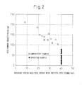
- FIG. 2 shows the relationship between the number density of coarse voids of steel wire and the breakage stress when a stranded wire breaks during twisting (40% means no breakage) prepared in the same way.
- FIG. 3 shows the relationship between the cooling rate between 800 to 700°C at patenting and the total of the area percentages of the non-pearlite structures and coarse pearlite structures after patenting obtained by the later explained Example 1.
- cooling rate is 25°C/s or more.
- the upper limit of the cooling rate is not particularly limited, however, if the cooling rate is made too high, the tensile strength (TS) after pearlite transformation will become higher than necessary and the direct drawability will be deteriorated, therefore 50°C/s or less is preferable.
- air blowers are concentratedly arranged at the ring overlapping parts, blowers are mounted at the both sides of conveyer, and the like, so as to control the cooling rate at the ring overlapping parts to 20°C/s or more.
- the lamellar spacing of the pearlite structures depends on transformation temperature. Coarse pearlite having large lamellar spacing is estimated to form near 650°C. In the actual production process of a ring-shaped steel rod, there will always be ring overlapping parts. At the overlapping parts, the cooling rate inevitably falls from the surrounding average locations, so even if the cooling rate of the austenite temperature region is controlled to 20°C/s or more, suppressing local rise up to near 650°C at the overlapping parts becomes extremely difficult. Therefore, even if the formation of coarse pearlite can be suppressed by adding Mo or W and B, it can be said to be impossible to make it zero.
- the coiling temperature range was specified to be a 800 to 950°C temperature region for the purpose of securing descaling property as well as suppressing the precipitation of B carbides and nitrides to secure solute B and suppressing the coarsening of austenite grain size so as to refine the non-pearlite structures and coarse pearlite structures and refine the size of voids formed from these structures.
- Mo and W have the effect of improving hardenability and are effective also in suppressing the formation of ferrite and reducing non-pearlite structures.
- the content of Mo was made 0.003 to 0.2% and the content of W was made 0.005 to 0.2%.
- the total amount is preferably made 0.2% or less, further preferably 0.16% or less.
- the preferable range of Mo is 0.01% to 0.15%, more preferably 0.02% to 0.10%, further preferably 0.04% to 0.08%.
- the preferable range of W is 0.01% to 0.15%, more preferably 0.02% to 0.10%, further preferably 0.04% to 0.08%.
- N forms nitrides with B in the steel and has the effect of preventing the coarsening of austenite grain size when heating. This effect is effectively exhibited by including 10 ppm or more of this. However, if the content increases too much exceeding 30 ppm, the amount of nitrides increases excessively and decreases the amount of solute B in the austenite. Further, solute N is liable to accelerate aging during drawing. Accordingly, the content of N was made 10 to 30 ppm.
- O forms complex inclusions with Si and the like and thereby is able to form soft inclusions not having negative effects on drawability.
- Such soft inclusions can be finely dispersed after hot rolling. Due to the pinning effect, it has the effect of refining the y grain size and improving the ductility of the patented steel rod. Therefore, the lower limit was made a value larger than 10 ppm. However, if increasing the content too much over 40 ppm, hard inclusions are formed and the drawability deteriorates, therefore the content of O was made over 10 ppm to 40 ppm.
- B When B exists in a solid solution state in the austenite, it concentrates at the grain boundaries and suppresses the formation of ferrite, degenerated pearlite, bainite, and other non-pearlite structures. Therefore, 3 ppm or more of solute B is necessary. On the other hand, if overly adding B, this will accelerate the precipitation of coarse Fe 3 (CB) 6 carbides in the austenite and have a negative effect on drawability. To satisfy the above, the lower limit of the content of B was made 4 ppm, and the upper limit was made 30 ppm (of which, 3 ppm or more is solute B).
- the preferable range of B is 6 ppm to 20 ppm, more preferably 8 ppm to 15 ppm, further preferably 10 ppm to 13 ppm. Further, the preferable range of solute B is 5 ppm to 15 ppm, more preferably 6 ppm to 12 ppm, further preferably 8 ppm to 10 ppm.
- P and S are impurities. Their contents are not particularly stipulated, however, from the viewpoint of similarly securing ductility as with conventional ultrafine steel wire, it is preferable for each to be no more than 0.02%.
- the steel used in the present invention has the above elements as its basic chemical components, however, one or two of the following elements may be actively added for the purpose of further improving strength, toughness, ductility, and other mechanical characteristics.
- Cr is an element effective in refining lamellar spacing of pearlite, improving the strength of the steel rod and the drawability of the steel rod. To effectively exhibit such an effect, it is preferable to add 0.1% or more. On the other hand, if the amount of Cr is too large, the transformation completion time will become long and martensite, bainite, and other overcooked structures will be liable to form in the steel rod after patenting. Further, the mechanical descaling property also becomes worse. Therefore, the upper limit when adding is made 0.5%.
- Ni is an element that does not contribute much to increasing the strength of the steel wire, but increases toughness. To effectively exhibit such an effect, it is preferable to add 0.1% or more. On the other hand, if excessively adding Ni, the transformation completion time will become long, therefore the upper limit when adding it is made 0.5%.
- Co is an element effective in suppressing precipitation of proeutectoid cementite in the rolled steel rod. To effectively exhibit such an effect, it is preferable to add 0.1% or more. On the other hand, even if excessively adding Co, its effect becomes saturated and the result is economically wasteful, therefore the upper limit when adding it is made 0.5%.
- V forms fine carbonitrides in the ferrite, whereby it prevents the coarsening of austenite during heating as well as contributes to increasing strength after rolling. To effectively exhibit such an effect, it is preferable to add 0.05% or more. However, if excessively adding it, the amount of carbonitrides formed will become too excessive and the grain size of the carbonitrides will become larger, therefore the upper limit when adding it is made 0.5%.
- Cu has an effect of increasing the corrosion resistance of the steel wire. To effectively exhibit such an effect, it is preferable to add 0.1% or more. However, if excessively adding it, it will react with S and CuS will precipitate at the grain boundaries, so defects will be caused on the steel ingot or the steel rod and the like during the production process. To prevent such negative effects, the upper limit when adding it is made 0.2%.
- Nb has an effect of increasing the corrosion resistance of the steel wire. To effectively exhibit such an action, it is preferable to add 0.05% or more. On the other hand, if excessively adding Nb, the transformation completion time will become long, therefore the upper limit when adding it is made 0.1%.
- a steel billet (steel slab) comprised of the above chemical components is heated, then is hot rolled into a rod having a diameter of 3 to 7 mm according to the final product size.
- the coiling temperature is made a temperature range of 800 to 950°C.
- the cooling rate from 800°C to 700°C is made 20°C/s or more, whereby the formation of proeutectoid ferrite and coarse pearlite are suppressed.
- Steel rod superior in ductility produced under the above production conditions and satisfying the above conditions of the chemical components and the structure is cold drawn and patented by final patenting once during that time, then is drawn by final cold drawing to obtain high strength steel wire having a tensile strength of 3600 MPa or more and having a number density of 100/mm 2 or less of voids of a length of 5 ⁇ m or more in the center of the steel wire.
- the true strain of cold drawing is 3 or more, preferably 3.5 or more.
- the cooling rate at the overlapping part of the steel rod decreases, whereby the transformation temperature rises and coarse pearlite is easily formed.
- the cooling rate from 800°C to 700°C was obtained by measuring the temperature of the ring overlapping part using a non-contact type thermometer every 0.5 m on a Stelmor conveyor, then measuring the required time t for cooling from 800°C to 700°C.
- the cooling rate was found to be (800-700)/t.
- the patented rolled rod was cut to samples which were subjected to tensile tests. Also, to measure the area percentages of the non-pearlite structures and coarse pearlite structures, ring-shaped steel rod having a ring diameter of 1.0 to 1.5 m were cut into eight equal parts, these eight samples were cut to samples of 10 mm length which were embedded in a resin so that the cross-sections of the center parts along the longitudinal direction of the rod (L direction) can be observed, abraded by alumina, corroded by saturated picral, and observed by SEM.
- the observation region of SEM was made a 1/4D portion. A 200 ⁇ 300 ⁇ m region was observed by 2000X.
- the area percentages of the degenerated pearlite structure in which ceminite was dispersed in a grain shape, the bainite parts in which plate-shaped cementite was coarsely dispersed at spacings of 3 times or more the spacings of the surrounding pearlite lamellar spacings, and the proeutectoid ferrite parts formed along the austenite grainboundaries were measured by image analysis as non-pearlite structures. Further, the area percentage of coarse pearlite structures having a lamellar spacing of 600 nm or more was measured by an image analysis system. These measurements were carried out using the above eight samples, and the average values and maximum values were found.
- the scale of the patented rolled rod was removed by pickling, then bonderization was used to impart a zinc phosphate coating.
- a 10 m long steel rod was prepared. This was drawn by single-head type drawing by an area reduction of 16 to 20% per pass, patented once or twice by a lead bath (LP) or fluidized bed patenting (FBP), then drawn by wet continuous drawing until a wire size of 0.15 to 0.3 mm to obtain steel wire having the final drawing size. Samples were taken from the obtained steel wire and subjected to a tensile test and measured for number density of voids.
- LP lead bath
- FBP fluidized bed patenting
- the number density of voids in the drawn steel wire was obtained by embedding and abrading a 10 mm long steel wire so that the L cross-section center part could be observed, corroding it by saturated picral, using SEM to photograph a 10 mm long, 20 ⁇ m wide region of the center of the steel rod at 5000X, measuring the number of voids of lengths of 5 ⁇ m or more, and dividing this by the observation area.
- the prepared steel wire was twisted into strands to investigate the occurrence of breakage and breakage stress. Twisting speed was 10000rpm and the applied load was increased gradually up to 40% of tensile strength of steel wires.
- the breakage stress is shown by the ratio of the tensile strength when breakage occurred with respect to the steel wire strength TS. Under the above working conditions, 40% exhibited no breakage.
- Nos. 1 to 29 are results using steels of the corresponding Nos. 1 to 29 of Table 1.
- Nos. 1 to 16 are invention examples, and Nos. 17 to 29 are comparative examples.
- the entries of "-" in the characteristics column of the steel wires of the comparative examples are cases where the wire broke at the final drawing pass or a prior pass.
- the final drawing diameter is the diameter at the time of that pass.
- FIG. 1 shows the relationship between the total value of the area percentages of the non-pearlite structures and coarse pearlite structures and the number density of the voids of the steel wire after final drawing
- FIG. 2 shows the relationship between the number density of the voids of the steel wire and the breakage stress when a wire breaks from twisting
- FIG. 3 shows the relationship between the cooling rate at 800 to 700°C of the steel rod after coiling and the total of the area percentages of the coarse pearlite structures and the non-pearlite structures.
- FIG. 1 shows that in the invention examples, if suppressing the non-pearlite and coarse pearlite percentage to 15% or less, in the drawn steel wire, the formation of voids lengths of 5 ⁇ m or more can be suppressed to 100/mm 2 or less
- FIG. 2 shows that in the invention examples, if suppressing the formation of voids to 100/mm 2 or less, the wire can be twisted into strands without wire breakage.
- FIG. 3 shows that by making the cooling rate in the steel rod at 800 to 700°C 20°C/s or more, the non-pearlite and coarse pearlite percentage to be suppressed to 15% or less.
- steel wires were obtained having high tensile strength without any wire breakage, and the steel wires could be twisted into strands without wire breakage due to the twisting.
- 21 is an example where the amount of C was excessive and proeutectoid cementite precipitation could not be suppressed, so the wire could not be drawn due to wire breakage.
- 25 to 27 are examples where B was not added, so the non-pearlite and the coarse pearlite could not be suppressed.
- TS ratio% Void number density //mm 2 1 5.5 860 Stelmor 25.5 1184 2.8 9.6 12.4 1.46 LP 575 1342 0.20 3789 None 40.0 80 Inv. ex. 2 5.5 880 Stelmor 23.3 1166 2.4 7.5 9.9 1.40 LP 550 1315 0.22 3455 None 40.0 70 Inv. ex. 3 5.5 860 Stelmor 30.5 1324 1.3 5.9 7.2 1.60 LP 575 1414 0.22 4055 None 40.0 28 Inv. ex. 4 5.0 820 Stelmor 33.0 1345 2.1 5.4 7.5 1.50 LP 600 1419 0.20 4132 None 40.0 65 Inv. ex.
- Example 2 the material was drawn in the same way as in Example 1 to obtain a steel wire having a final drawing diameter. Samples were extracted from the obtained steel wire and subjected to a tensile test and measured for number density of voids.
- Example 2 the prepared steel wire was used and twisted in the same way as in Example 1 and examined for the occurrence of breakage of wire and the breakage stress.
- Table 4 The conditions for producing the rolled steel rod, the conditions for the final patenting, and the characteristics of the obtained steel rod and steel wire are shown in Table 4.
- Nos. a to h are examples using steels of the corresponding Nos. a to h of Table 3.
- Nos. a to d are invention example and
- Nos. e to h are comparative examples.
- steel wires were obtained having high tensile strength without any wire breakage. Further, these steel wires could be twisted into strands without the wires breaking from the twisting.
- Samples were taken from the patented rolled steel rod in the same way as Example 1 and subjected to a tensile test and observed by SEM.
- the rod was drawn in the same way as in Example 1 to obtain a steel wire having a final drawing diameter. Samples were extracted from the obtained steel wire and subjected to a tensile test and measured for number density of voids.
- Example 2 the prepared steel wire was used and twisted in the same way as in Example 1 and examined for the occurrence of breakage of wire and the breakage stress.
- Nos. 1 to 16 are invention examples using steels of the corresponding Nos. 1 to 16 of Table 5.
- 17 to 28 are comparative examples.
- the entries of "-" in the characteristics column of the steel wires of the comparative examples are cases where the wire broke at the final drawing pass or a prior pass.
- the final drawing diameter is the diameter at the time of that pass.
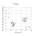
- FIGS. 4 to 6 show similar relationships as FIGS. 1 to 3 of Example 1.
- FIGS. 4 to 6 show that even when using steel containing W, similar relationships to Example 1 using steel containing Mo are obtained.
- steel wires were obtained having high tensile strength without any wire breakage. Further, the steel wires could be twisted into strands without the wires breaking from twisting.
- 17 is an example where the coiling temperature was low, so B nitrides and carbides precipitated before patenting, so the amount of solute B cannot be secured, therefore non-pearlite and coarse pearlite could not be suppressed.
- 19, 22, 24, 26, and 29 are examples where the amount of B was low or not added, so non-pearlite and coarse pearlite could not be suppressed.
- the cooling rate was small, so the TS was low and there was a large amount of non-pearlite and coarse pearlite.
- 21 is an example where the amount of B was excessive, a large amount of B carbide and proeutectoid cementite ended up precipitating at the austenite grain boundaries, and the drawing characteristics were poor.
- Samples were taken from the patented rolled steel rod in the same way as Example 1 and subjected to a tensile test and observed by SEM.
- Example 2 the material was drawn in the same way as in Example 1 to obtain a steel wire having a final drawing diameter. Samples were extracted from the obtained steel wire and subjected to a tensile test and measured for number density of voids.
- Example 2 Further, the obtained steel wire was used and twisted in the same way as in Example 1 and examined for the occurrence of breakage of wire and the breakage stress.
- Nos. a to h are examples using steels of the corresponding Nos. a to h of Table 7, Nos. a to d are invention examples, and Nos. e to h are comparative examples.
- steel wires were obtained having high tensile strength without any wire breakage. Further, the steel wires could be formed into strands without the wires breaking from twisting.
Abstract
Description
- The present invention relates to a steel rod superior in ductility, a high strength steel wire superior in ductility and twistability produced using the steel rod, and methods of production of the same. More specifically, it relates to a rolled steel rod superior in ductility for obtaining steel wire suitable for steel cord used as reinforcement material in for example automobile radial tires, belts for industrial use, and the like, further a sawing wire, and other applications, a high strength steel wire mentioned above obtained from the rolled rod, and methods of production of the same.
- Steel wire for steel cord used as reinforcement material for automobile radial tires, various belts, and hoses or steel wire for sawing wire is generally produced by hot rolling a steel billet, then controllably cooling it to obtain a steel rod (rolled rod) of a diameter of 4 to 6 mm, and drawing this rolled rod to a diameter 0.15 to 0.40 mm ultrafine wire. Further, these ultrafine steel wires are twisted together to form steel wire strands to thereby produce steel cord.
- The drawing process comprises drawing the 4 to 6 mm rolled steel rod by primary drawing to a diameter of 3 to 4 mm, then intermediate patenting it and further drawing it by secondary drawing to a 1 to 2 mm diameter. After this, final patenting, brass plating and final wet drawing are performed. Final diameter of steel wire is 0.15 to 0.40mm.
- In recent years, to reduce production costs, intermediate patenting has been omitted and the rolled rod after controlled cooling has been drawn directly up to the final patenting wire diameter of 1 to 2 mm in increasing cases. Therefore, direct drawability from the rolled rod, is being demanded. The ductility and workability of the rolled rod are then becoming important.
- The index showing the ductility of the steel rod, that is the area reduction, depends on the austenite grain size. It rises as the austenite grain size is refined. Attempts have been therefore made using Nb, Ti, B, and other carbides and nitrides as pinning particles so as to refine the austenite grain size.
- For example, Japanese Patent Publication (A) No.
8-3639 - Japanese Patent Publication (A) No.
2001-131697 - However, these additive elements are expensive, so cause cost increase. Further, Nb forms coarse carbides and nitrides and Ti forms coarse oxides, so there have been cases of breakage if drawing up to a thin wire size of a diameter of 0.40 mm or less. Further, according to verification by the inventors, it has been confirmed that with BN pinning, refining of austenite grain size to a degree having an effect on the area reduction rate is difficult.
- On the other hand, as shown in Japanese Patent Publication (A) No.
8-3639 - The present invention was made in consideration of the above situation and has as its object to provide a steel rod superior in ductility for producing steel wire suitable for steel cord, sawing wire, and other applications and steel wire produced from the steel rod and to provide a method of producing the steel rod with high productivity and good yield in low cost.
- The inventors took note of the coarse voids which occur in the drawing process as the factor causing deterioration of the ductility of the steel rod and wire. Further, the inventors found that if the formation of such voids can be suppressed, the direct drawability of a steel rod rises and steel wire with increased twistability can be obtained.
- Based on such findings, the present invention solves the above problems by the steel rod shown in (1) and (2), the steel wire shown in (3), the method of producing the steel rod shown in (4), and the method of producing the steel wire shown in (5).
- (1) Steel rod for high strength steel wire superior in ductility characterized by the chemical components containing, by mass% or mass ppm, C: 0.80 to 1.20%, Si: 0.1 to 1.5%, Mn: 0.1 to 1.0%, Al: 0.01% or less, Ti: 0.01% or less, one or both of W: 0.005 to 0.2% and Mo: 0.003 to 0.2%, N: 10 to 30 ppm, B: 4 to 30 ppm (of which, solute B is 3 ppm or more), and O: 10 to 40 ppm, having a balance of Fe and unavoidable impurities, having an area percentage of pearlite structures of 97% or more, having a balance of non-pearlite structures comprising bainite, degenerated pearlite and proeutectoid ferrite, and having a total of the area percentage of the non-pearlite structures and the area percentage of the coarse pearlite structures where the apparent lamellar spacing is 600 nm or more of 15% or less.
- (2) Steel rod for high strength steel wire superior in ductility as set forth in (1) characterized by further containing as components, by mass%, at least one of Cr: 0.5% or less, Ni: 0.5% or less, Co: 0.5% or less, V: 0.5% or less, Cu: 0.2% or less, and Nb: 0.1% or less.
- (3) High strength steel wire superior in ductility obtained by the process comprising patenting, then drawing a steel rod set forth in (1) or (2), said steel wire characterized by having a tensile strength of 3600 MPa or more and a number density of voids of lengths of 5 µm or more of 100/mm2 or less at the center.
- (4) A method of producing steel rod for high strength steel wire superior in ductility as set forth in (1) or (2), characterized by hot rolling a steel billet of the chemical components set forth in (1) or (2) into a steel rod having a diameter of 3 to 7 mm, coiling this steel rod at a temperature region of 800 to 950°C, then patenting it by a cooling method giving a cooling rate of 20°C/s or more while being cooled from 800°C to 700°C.
- (5) A method of producing high strength steel wire superior in ductility as set forth in (3), characterized by drawing the steel rod produced by the method of production as set forth in (4), then patenting it, then further cold drawing it.
- By application of the present invention, high strength steel wire superior in ductility, in particular twistability, used in steel cord and sawing wires can be obtained with high productivity and good yield in low cost from high strength steel rod superior in ductility.
-
-
FIG. 1 is a view showing the relationship between the total value of the area percentages of the coarse pearlite and the non-pearlite of a rolled steel rod using steel containing Mo and the void number density after drawing. -
FIG. 2 is a view showing the relationship between the void number density of steel wire using steel containing Mo and breakage stress when a stranded steel wirebreaks during twisting (40% means no breakage). -
FIG. 3 is a view showing the relationship between the cooling rate between 800 to 700°C after coiling of rolled steel rod using steel containing Mo and the total value of the area percentages of the coarse pearlite and non-pearlite after cooling. -
FIG. 4 is a view showing the relationship between the total value of the area percentages of the coarse pearlite and non-pearlite of rolled steel rod using steel containing W and a void percentage after drawing. -
FIG. 5 is a view showing the relationship between the void number density of steel wire using steel containing W and breakage stress when a stranded steel wire breaks during twisting (40% means no breakage). -
FIG. 6 is a view showing the relationship between the cooling rate between 800 to 700°C after coiling of rolled steel rod using steel containing W and the total value of the area percentages of the coarse pearlite and non-pearlite after cooling. -
FIG. 7 is a view using photographs for explaining the structure of the steel rod, where (a) shows an example of a non-pearlite structure and (b) an example of a coarse pearlite structure. -
FIG. 8 is a view using photographs for explaining the coarse voids formed in steel wire after drawing. - The inventors investigated and researched the influences of voids, which are formed during the process of drawing a steel rod and remained in the steel wire after drawing, on the ductility of the steel wire and obtained the following discoveries.
- (a) Drawability generally rises by reducing the amount of C and increasing a soft phase, that is ferrite, degenerated pearlite and bainite (hereinafter referred to as the "non-pearlite structures"). This is because strain from working concentrates to the soft non-pearlite structures dispersed in a network, and the work hardening proceeds macroscopically uniformly.
However, if increasing the amount of C to 0.7% or more, particularly to 0.8% or more, to stably obtain high strength steel wire, the non-pearlite structure decreases and disperses.FIG. 7(a) shows an example of such non-pearlite structures.
Large strain locally concentrates to such dispersed non-pearlite structures during drawing whereby voids are formed early on. In particular, if large non-pearlite structures disperse, coarse voids will be formed and will remain during subsequent intermediate patenting and final drawing and thereby degrade the drawability.FIG. 8 shows an example of coarse voids. - (b) Coarse pearlite structures of which lamellar spacing is several times greater than the average lamellar spacing are soft and degrade the drawability at the final drawing for the same reasons as the above.
At the time of Stelmor patenting after steel rod rolling and coiling, the cooling rate at the ring overlapping area of the coiled steel rod might be low. It is considered that such coarse pearlite forms at a comparatively high temperature due to the low- cooling rate.
To suppress deterioration of ductility during drawing, reduction of the area fraction of the coarse pearlite structures to suppress the formation of coarse voids is effective. According to the results of SEM observation, if structures where the apparent lamellar spacing is 600 nm or more (hereinafter referred to as "coarse pearlite") increase, the voids increase in drawn wire. Note that,FIG. 7(b) shows an example of a coarse pearlite structure. - (c) To suppress the formation of voids caused by non-pearlite structures and coarse pearlite and suppress the deterioration of ductility during drawing, making the pearlite area percentage 97% or more and making the total of the non-pearlite area percentage and the coarse
pearlite area percentage 15% or less is effective. - (d) Mo and W concentrate at the interface of the pearlite and base phase austenite and have the effect of suppressing the growth of pearlite by so-called solute drag. By appropriately adding these elements, it is possible to suppress only the growth of the pearlite in a 600°C or higher temperature region and possible to decrease coarse pearlite by using the conventional facilities without reducing productivity.
Further, Mo and W also have the effect of increasing hardenability and suppressing formation of ferrite and are effective in reducing non-pearlite structures.
However, if these elements are excessively added, pearlite growth in all temperature regions will be suppressed, the patenting will require a long time, and the productivity will be lowered. Also, coarse MO2C carbides and W2C carbides will precipitate and the drawability will drop. - (e) B segregates at the austenite grain boundaries and suppresses the formation of ferrite, degenerated pearlite, bainite and other non-pearlite structures formed from the austenite grain boundary during cooling from the austenite temperature at patenting and suppresses the formation of coarse pearlite by the effect of improvement of the hardenability.
B forms compounds with N, so the amount of B segregated at the grain boundaries is determined by the total amount of B, amount of N, and the heating temperature before pearlite transformation. If the amount of solute B is low, the above effects are small, and if excessive, coarse Fe23(CB)6 precipitates before pearlite transformation and the drawability will deteriorate. - (f) By simultaneously adding one or both of Mo and W and B and patenting under heat treatment conditions where solute B can be secured, formation of non-pearlite structures and coarse pearlite are further suppressed.
- (g) Steel wire drawn using steel rod where the area percentage of the non-pearlite structures and the coarse pearlite is suppressed and as a result formation of coarse voids is suppressed is superior in twistability. In particular, voids with a length of 5 µm or more in the steel wire may develop into cracks. If the number density of such voids can be suppressed to 100/mm2 or less, wire breakage when twisting the wires together can be suppressed.
- The present invention was made based on the above findings. Below, the present invention will be sequentially explained. Note that, in the explanation below, the % and ppm of the contents of the components mean mass% and mass ppm respectively.
- The steel rod is patented by controlled cooling after hot rolling and coiling and made pearlite structures of an area percentage of 97% or more and a balance of non-pearlite structures comprising bainite, degenerated pearlite, and proeutectoid ferrite. This is because if less than 97%, the necessary steel rod strength cannot be secured and the ductility during drawing will deteriorate.
- Pearlite transformation proceeds by the nucleation of pearlite at austenite grainboundaries and growth of pearlite. Until layered structures forming the nuclei of pearlite structures are formed, the structures are non-pearlite ones witch irregular growth of ferrite and cementite, so the steel rod will usually never have 100% pearlite structures.
- The direct drawability of the patented rolled steel rod is correlated with the area percentage of the non-pearlite structures and the coarse pearlite structures in the steel rod. If the total of the area percentages of the non-pearlite structures and coarse pearlite structures can be suppressed to 15% or less, early void formation during drawing is suppressed, and the drawability (ductility) during final drawing after intermediate patenting is inproved.
- Further, if the total of the area percentages of the non-pearlite structures and coarse pearlite structures of the steel rod is made 15% or less, the number density of coarse voids remaining in the steel wire after drawing decreases, the ductility of the steel wire rises, and breakage during twisting becomes extremely infrequent.
- The voids remaining in the steel wire are elongated long in the drawing direction as shown in
FIG. 8 . According to a study by the inventors, it is revealed that what affects the ductility of steel wire are the coarse voids having a length of 5 µm or more, and that if making the total of the area percentages of the non-pearlite structures and the coarse pearlite structures of thesteel rod 15% or less, the number density of such voids becomes 100/mm2 or less at the center of the steel wire, and the twistability of the steel wire is improved. -
FIG. 1 shows the relationship between the total of the area percentages of the non-pearlite structures and coarse pearlite structures of a steel rod before drawing and the number density of the coarse voids of the steel wire after drawing prepared using the values obtained from Example 1 explained later (example using steel containing Mo alone). Further,FIG. 2 shows the relationship between the number density of coarse voids of steel wire and the breakage stress when a stranded wire breaks during twisting (40% means no breakage) prepared in the same way. - These drawings show that if the total of the area percentages of the non-pearlite and the coarse pearlite of the steel rod is made 15% or less, the number density of coarse voids of the steel wire will become 100/mm2 or less and twisting without breakage can be performed.
- To reduce the non-pearlite structures and coarse pearlite structures, it is effective to control the amounts of C, Si, and Mn in the steel billet or slab to predetermined ranges and, as in the above, simultaneously add one or both of Mo and W and B in ranges of Mo: 0.003 to 0.2%, W: 0.005 to 0.2%, and B: 4 to 30 ppm, then hot roll the steel billet to a 3 to 7 mm rod size and coil it at a 800 to 950°C temperature region, then patent it by a cooling method giving a cooling rate of 20°C/s or more while being cooled from 800°C to 700°C.
-
FIG. 3 shows the relationship between the cooling rate between 800 to 700°C at patenting and the total of the area percentages of the non-pearlite structures and coarse pearlite structures after patenting obtained by the later explained Example 1. - If making the cooling rate less than 20°C/s, even if steel having the above chemical components is used, B precipitates as BN, and the amount of solute B decreases, thereby making it difficult to suppress the non-pearlite structures and coarse pearlite structures. A preferable cooling rate is 25°C/s or more. The upper limit of the cooling rate is not particularly limited, however, if the cooling rate is made too high, the tensile strength (TS) after pearlite transformation will become higher than necessary and the direct drawability will be deteriorated, therefore 50°C/s or less is preferable.
- To control the cooling rate, in a Stelmor system, air blowers are concentratedly arranged at the ring overlapping parts, blowers are mounted at the both sides of conveyer, and the like, so as to control the cooling rate at the ring overlapping parts to 20°C/s or more.
- Note that, the lamellar spacing of the pearlite structures depends on transformation temperature. Coarse pearlite having large lamellar spacing is estimated to form near 650°C. In the actual production process of a ring-shaped steel rod, there will always be ring overlapping parts. At the overlapping parts, the cooling rate inevitably falls from the surrounding average locations, so even if the cooling rate of the austenite temperature region is controlled to 20°C/s or more, suppressing local rise up to near 650°C at the overlapping parts becomes extremely difficult. Therefore, even if the formation of coarse pearlite can be suppressed by adding Mo or W and B, it can be said to be impossible to make it zero.
- In the above, the coiling temperature range was specified to be a 800 to 950°C temperature region for the purpose of securing descaling property as well as suppressing the precipitation of B carbides and nitrides to secure solute B and suppressing the coarsening of austenite grain size so as to refine the non-pearlite structures and coarse pearlite structures and refine the size of voids formed from these structures.
- Chemical components of steel rod and steel wire:
- C: C is an element effective in increasing strength. If the content of this is less than 0.80%, it becomes difficult to stably give a high strength of 3600 MPa or more to a final product steel wire and, at the same time, formation of proeutectoid ferrite is accelerated at the austenite grain boundaries and it becomes difficult to obtain the necessary pearlite structure area percentage. On the other hand, if increasing the content of C over 1.20%, not only net-shaped proeutectoid cementite form at the austenite grain boundaries and make breakage occur easily during drawing, but also the toughness and ductility of the ultrafine wire after final drawing is significantly deteriorated. Accordingly, the content of C was made 0.80 to 1.20%.
- Si: Si is an element effective for increasing strength. Further, it is an element useful as a deoxidizing agent and an element necessary when dealing with steel not containing Al. If its content is less than 0.1%, the deoxidizing effect is too small. On the other hand, if increasing the amount of Si over 1.5%, the formation of proeutectoid ferrite is accelerated even in hypereutectoid steel and the drawability deteriorates. Further, a drawing process using mechanical descaling (hereinafter abbreviated as "MD") becomes difficult. Accordingly, the content of Si was made 0.1 to 2.5%. The preferable upper limit for the amount of Si is less than 0.6%, more preferably less than 0.35%.
- Mn: Mn, like Si, is an element useful as a deoxidizing agent. Further, it is effective in improving hardenability and increasing the strength of steel rod. Further, Mn fixes the S in the steel as MnS and prevents hot embrittlement. If the content is less than 0.1%, it is difficult to obtain this effect. On the other hand, if the content exceeds 1.0%, it segregates at the center of the steel rod and causes martensite and bainite formation during or after patenting, whereby the drawability deteriorates. Accordingly, the content of Mn was made 0.1 to 1.0%.
- Al: Al forms hard non-deforming Al-based nonmetallic inclusions and causes for ductility deterioration and drawability deterioration, therefore, so as not to cause such deterioration, the content of Al was made 0.01 or less, including 0%.
- Ti: Ti forms hard non-deforming oxides and causes for ductility deterioration and drawability deterioration, therefore, so as not to cause such deterioration, the content of Ti was made 0.01 or less, including 0%.
- Mo and W: Mo and W concentrate at the interface between the pearlite and the base phase austenite and have the effect of suppressing the growth of pearlite by the so-called solute drag. They are added alone or in combination.
- By adding 0.003% or more of Mo or 0.005% or more of W, it is possible to suppress only the growth of pearlite in a high temperature region of 600°C or more, and formation of coarse pearlite can be suppressed. Further, Mo and W have the effect of improving hardenability and are effective also in suppressing the formation of ferrite and reducing non-pearlite structures.
- However, if either is added excessively over 0.2%, pearlite growth in all temperature regions will be suppressed, the patenting will take a long time, and productivity will be lowered. Also, coarse MO2C carbide and W2C carbide will precipitate, then the drawability will deteriorate.
- Accordingly, the content of Mo was made 0.003 to 0.2% and the content of W was made 0.005 to 0.2%. When both Mo and W are added, the total amount is preferably made 0.2% or less, further preferably 0.16% or less.
- The preferable range of Mo is 0.01% to 0.15%, more preferably 0.02% to 0.10%, further preferably 0.04% to 0.08%.
- Further, the preferable range of W is 0.01% to 0.15%, more preferably 0.02% to 0.10%, further preferably 0.04% to 0.08%.
- N: N forms nitrides with B in the steel and has the effect of preventing the coarsening of austenite grain size when heating. This effect is effectively exhibited by including 10 ppm or more of this. However, if the content increases too much exceeding 30 ppm, the amount of nitrides increases excessively and decreases the amount of solute B in the austenite. Further, solute N is liable to accelerate aging during drawing. Accordingly, the content of N was made 10 to 30 ppm.
- O: O forms complex inclusions with Si and the like and thereby is able to form soft inclusions not having negative effects on drawability. Such soft inclusions can be finely dispersed after hot rolling. Due to the pinning effect, it has the effect of refining the y grain size and improving the ductility of the patented steel rod. Therefore, the lower limit was made a value larger than 10 ppm. However, if increasing the content too much over 40 ppm, hard inclusions are formed and the drawability deteriorates, therefore the content of O was made over 10 ppm to 40 ppm.
- Note that, when including Mo alone, it is preferable to include O in an amount over 20 ppm.
- B: When B exists in a solid solution state in the austenite, it concentrates at the grain boundaries and suppresses the formation of ferrite, degenerated pearlite, bainite, and other non-pearlite structures. Therefore, 3 ppm or more of solute B is necessary. On the other hand, if overly adding B, this will accelerate the precipitation of coarse Fe3(CB)6 carbides in the austenite and have a negative effect on drawability. To satisfy the above, the lower limit of the content of B was made 4 ppm, and the upper limit was made 30 ppm (of which, 3 ppm or more is solute B).
- The preferable range of B is 6 ppm to 20 ppm, more preferably 8 ppm to 15 ppm, further preferably 10 ppm to 13 ppm. Further, the preferable range of solute B is 5 ppm to 15 ppm, more preferably 6 ppm to 12 ppm, further preferably 8 ppm to 10 ppm.
- P and S: These are impurities. Their contents are not particularly stipulated, however, from the viewpoint of similarly securing ductility as with conventional ultrafine steel wire, it is preferable for each to be no more than 0.02%.
- The steel used in the present invention has the above elements as its basic chemical components, however, one or two of the following elements may be actively added for the purpose of further improving strength, toughness, ductility, and other mechanical characteristics.
- Cr: 0.5% or less, Ni: 0.5% or less, Co: 0.5% or less, V: 0.5% or less, Cu: 0.2% or less, and Nb: 0.1% or less.
- Below, each element will be explained.
- Cr: Cr is an element effective in refining lamellar spacing of pearlite, improving the strength of the steel rod and the drawability of the steel rod. To effectively exhibit such an effect, it is preferable to add 0.1% or more. On the other hand, if the amount of Cr is too large, the transformation completion time will become long and martensite, bainite, and other overcooked structures will be liable to form in the steel rod after patenting. Further, the mechanical descaling property also becomes worse. Therefore, the upper limit when adding is made 0.5%.
- Ni: Ni is an element that does not contribute much to increasing the strength of the steel wire, but increases toughness. To effectively exhibit such an effect, it is preferable to add 0.1% or more. On the other hand, if excessively adding Ni, the transformation completion time will become long, therefore the upper limit when adding it is made 0.5%.
- Co: Co is an element effective in suppressing precipitation of proeutectoid cementite in the rolled steel rod. To effectively exhibit such an effect, it is preferable to add 0.1% or more. On the other hand, even if excessively adding Co, its effect becomes saturated and the result is economically wasteful, therefore the upper limit when adding it is made 0.5%.
- V: V forms fine carbonitrides in the ferrite, whereby it prevents the coarsening of austenite during heating as well as contributes to increasing strength after rolling. To effectively exhibit such an effect, it is preferable to add 0.05% or more. However, if excessively adding it, the amount of carbonitrides formed will become too excessive and the grain size of the carbonitrides will become larger, therefore the upper limit when adding it is made 0.5%.
- Cu: Cu has an effect of increasing the corrosion resistance of the steel wire. To effectively exhibit such an effect, it is preferable to add 0.1% or more. However, if excessively adding it, it will react with S and CuS will precipitate at the grain boundaries, so defects will be caused on the steel ingot or the steel rod and the like during the production process. To prevent such negative effects, the upper limit when adding it is made 0.2%.
- Nb: Nb has an effect of increasing the corrosion resistance of the steel wire. To effectively exhibit such an action, it is preferable to add 0.05% or more. On the other hand, if excessively adding Nb, the transformation completion time will become long, therefore the upper limit when adding it is made 0.1%.
- A steel billet (steel slab) comprised of the above chemical components is heated, then is hot rolled into a rod having a diameter of 3 to 7 mm according to the final product size. At that time, as explained above, the coiling temperature is made a temperature range of 800 to 950°C. In the cooling after coiling, the cooling rate from 800°C to 700°C is made 20°C/s or more, whereby the formation of proeutectoid ferrite and coarse pearlite are suppressed.
- Steel rod superior in ductility produced under the above production conditions and satisfying the above conditions of the chemical components and the structure is cold drawn and patented by final patenting once during that time, then is drawn by final cold drawing to obtain high strength steel wire having a tensile strength of 3600 MPa or more and having a number density of 100/mm2 or less of voids of a length of 5 µm or more in the center of the steel wire. During this time, the true strain of cold drawing is 3 or more, preferably 3.5 or more.
- Next, examples will be given to explain the present invention in more detail, however, the present invention is not limited to the following examples and can of course be carried out with changes added appropriately within the range meeting the gist of the present invention. These are all within the technical scope of the present invention.
- This is an example of the case using steel containing Mo. A billet using steel having each of the chemical components shown in Table 1 was heated, then hot rolled to rod having a diameter of 3 to 7 mm. The hot rolled rod was coiled in a ring shape at a predetermined temperature, then patented by the Stelmor treatment.
- When patenting by the Stelmor treatment, the cooling rate at the overlapping part of the steel rod decreases, whereby the transformation temperature rises and coarse pearlite is easily formed. The cooling rate from 800°C to 700°C was obtained by measuring the temperature of the ring overlapping part using a non-contact type thermometer every 0.5 m on a Stelmor conveyor, then measuring the required time t for cooling from 800°C to 700°C. The cooling rate was found to be (800-700)/t.
- The patented rolled rod was cut to samples which were subjected to tensile tests. Also, to measure the area percentages of the non-pearlite structures and coarse pearlite structures, ring-shaped steel rod having a ring diameter of 1.0 to 1.5 m were cut into eight equal parts, these eight samples were cut to samples of 10 mm length which were embedded in a resin so that the cross-sections of the center parts along the longitudinal direction of the rod (L direction) can be observed, abraded by alumina, corroded by saturated picral, and observed by SEM.
- The observation region of SEM was made a 1/4D portion. A 200×300 µm region was observed by 2000X. The area percentages of the degenerated pearlite structure in which ceminite was dispersed in a grain shape, the bainite parts in which plate-shaped cementite was coarsely dispersed at spacings of 3 times or more the spacings of the surrounding pearlite lamellar spacings, and the proeutectoid ferrite parts formed along the austenite grainboundaries were measured by image analysis as non-pearlite structures. Further, the area percentage of coarse pearlite structures having a lamellar spacing of 600 nm or more was measured by an image analysis system. These measurements were carried out using the above eight samples, and the average values and maximum values were found.
- To obtain the drawing characteristics of the steel rod, the scale of the patented rolled rod was removed by pickling, then bonderization was used to impart a zinc phosphate coating. A 10 m long steel rod was prepared. This was drawn by single-head type drawing by an area reduction of 16 to 20% per pass, patented once or twice by a lead bath (LP) or fluidized bed patenting (FBP), then drawn by wet continuous drawing until a wire size of 0.15 to 0.3 mm to obtain steel wire having the final drawing size. Samples were taken from the obtained steel wire and subjected to a tensile test and measured for number density of voids.
- The number density of voids in the drawn steel wire was obtained by embedding and abrading a 10 mm long steel wire so that the L cross-section center part could be observed, corroding it by saturated picral, using SEM to photograph a 10 mm long, 20 µm wide region of the center of the steel rod at 5000X, measuring the number of voids of lengths of 5 µm or more, and dividing this by the observation area.
- Next, the prepared steel wire was twisted into strands to investigate the occurrence of breakage and breakage stress. Twisting speed was 10000rpm and the applied load was increased gradually up to 40% of tensile strength of steel wires. The breakage stress is shown by the ratio of the tensile strength when breakage occurred with respect to the steel wire strength TS. Under the above working conditions, 40% exhibited no breakage.
- The results are shown in Table 2. In Table 2, Nos. 1 to 29 are results using steels of the corresponding Nos. 1 to 29 of Table 1. Nos. 1 to 16 are invention examples, and Nos. 17 to 29 are comparative examples. The entries of "-" in the characteristics column of the steel wires of the comparative examples are cases where the wire broke at the final drawing pass or a prior pass. The final drawing diameter is the diameter at the time of that pass.
- Based on the values of Table 2,
FIG. 1 shows the relationship between the total value of the area percentages of the non-pearlite structures and coarse pearlite structures and the number density of the voids of the steel wire after final drawing, whileFIG. 2 shows the relationship between the number density of the voids of the steel wire and the breakage stress when a wire breaks from twisting. Further,FIG. 3 shows the relationship between the cooling rate at 800 to 700°C of the steel rod after coiling and the total of the area percentages of the coarse pearlite structures and the non-pearlite structures. -
FIG. 1 shows that in the invention examples, if suppressing the non-pearlite and coarse pearlite percentage to 15% or less, in the drawn steel wire, the formation of voids lengths of 5 µm or more can be suppressed to 100/mm2 or less, further,FIG. 2 shows that in the invention examples, if suppressing the formation of voids to 100/mm2 or less, the wire can be twisted into strands without wire breakage. Further,FIG. 3 shows that by making the cooling rate in the steel rod at 800 to 700°C 20°C/s or more, the non-pearlite and coarse pearlite percentage to be suppressed to 15% or less. - As shown in Table 2, in the invention examples, steel wires were obtained having high tensile strength without any wire breakage, and the steel wires could be twisted into strands without wire breakage due to the twisting.
- As opposed to this, in the comparative examples, there were the following problems. Either the wire broke during drawing or broke during twisting into strands after drawing.
- 17 is an example where the coining temperature was low, therefore B nitrides and carbides precipitated before patenting and the amount of solute B could not be secured, so the non-pearlite and the coarse pearlite could not be suppressed.
- 18 is an example where the amount of B was low, so the non-pearlite and the coarse pearlite could not be suppressed.
- 19 is an example where the amount of B was excessive, a large amount of B carbides and proeutectoid cementite ended up precipitating at the austenite grain boundaries, and the drawability was inferior.
- 20 is an example where the amount of Si was excessive and non-pearlite (proeutectoid ferrite) precipitation could not be suppressed.
- 21 is an example where the amount of C was excessive and proeutectoid cementite precipitation could not be suppressed, so the wire could not be drawn due to wire breakage.
- 22 is an example where the amount of Mn was excessive and pearlite transformation did not finish during Stelmore process, so the drawability deteriorated and the wire broke.
- 23 is an example where the coiling temperature after rolling was too high, so BN precipitated in a large amount during the cooling process and, further, the austenite grains became coarsened, so coarse grain boundary ferrite formed and the ductility deteriorated.
- 24 is an example where the amount of Mo was excessive and the pearlite transformation did not finish during Stelmore process, so primary drawing could not be performed.
- 25 to 27 are examples where B was not added, so the non-pearlite and the coarse pearlite could not be suppressed.
- 28 is an example where the cooling rate after coiling was small, so the tensile strength (TS) was also low and the non-pearlite and coarse pearlite were both large in amount.
- 29 is an example where no Mo was added, so the formation of coarse pearlite could not be suppressed.
Table 1 No. Element (mass%, mass ppm) Remarks C Si Mn P S B (ppm) Solute B (ppm) Al Ti N (ppm) 0 (ppm) Mo Cr Ni Cu V Co Nb 1 0.82 0.30 0.45 0.019 0.025 24 11 0.001 20 21 0.005 Inv. ex. 2 0.82 0.20 0.51 0.015 0.013 13 9 0.001 22 31 0.186 Inv. ex. 3 0.92 0.20 0.57 0.010 0.007 12 8 0.004 20 28 0.040 0.10 Inv. ex. 4 0.92 0.20 0.3 0.019 0.025 8 6 27 25 0.030 0.18 Inv. ex. 5 0.93 0.20 0.32 0.008 0.007 11 7 0.003 26 23 0.003 0.22 Inv. ex. 6 0.92 0.20 0.49 0.010 0.009 9 6 24 24 0.025 0.10 Inv. ex. 7 0.92 0.60 0.5 0.025 0.020 8 5 0.001 25 23 0.050 0.03 0.05 Inv. ex. 8 1.02 0.20 0.3 0.008 0.008 11 6 27 21 0.005 0.23 Inv. ex. 9 1.02 0.13 0.3 0.008 0.008 12 7 26 26 0.030 0.18 Inv. ex. 10 1.02 0.20 0.5 0.008 0.008 13 7 C.004 25 21 0.060 0.21 Inv. ex. 11 1.02 0.20 0.5 0.010 0.008 4 3 25 38 0.020 0.05 0.10 Inv. ex. 12 1.02 0.20 0.5 0.008 0.010 12 8 27 22 0.110 0.20 Inv. ex. 13 0.92 0.20 0.4 0.008 0.008 15 11 25 21 0.030 0.06 Inv. ex. 14 0.91 0.20 0.3 0.008 0.008 21 13 0.003 26 24 0.050 0.20 0.20 0.02 Inv. ex. 15 0.90 0.20 0.49 0.009 0.010 9 6 21 23 0.004 Inv. ex. 16 1.12 0.22 0.3 0.008 0.008 28 19 0.001 27 35 0.042 Inv. ex. 17 0.82 0.30 0.5 0.008 0.007 11 6 35 22 0.010 0.20 Comp. ex. 18 0.82 0.20 0.5 0.010 0.009 2 0.010 50 28 0.030 Comp. ex. 19 0.90 0.20 0.8 0.010 0.009 60 32 0.005 25 18 0.015 0.10 Comp. ex. 20 0.87 1.70 0.4 0.015 0.013 20 11 0.010 25 22 0.012 Comp. ex. 21 1.30 1.00 0.3 0.015 0.013 20 12 0.030 25 17 0.020 0.30 Comp. ex. 22 0.92 0.30 1.5 0.015 0.013 20 10 0.025 25 21 0.018 0.20 Comp. ex. 23 0.82 1.00 0.5 0.025 0.020 20 13 0.030 35 20 0.018 0.20 Comp. ex. 24 0.96 0.20 0.5 0.610 0.009 12 7 0.010 25 23 0.250 0.10 Comp. ex. 25 0.82 0.20 0.5 0.010 0.009 0.010 25 24 0.005 Comp. ex. 26 1.02 0.20 0.5 0.010 0.009 0.010 25 22 0.010 Combo ex. 27 0.92 0.20 0.5 0.010 0.009 0.010 25 20 0.050 Comp. ex. 28 0.82 0.20 0.45 0.019 0.025 24 19 25 19 Comp. ex. 29 0.93 0.20 0.31 0.008 0.007 11 8 0.001 26 23 0.22 Comp. ex. Note: Blanks indicate no addition. Table 2 Steel rod production conditions Characteristics rod after of rolled steel patenting Finial patenting conditions and characteristics Steel wire characteristics Remarks No. Dimam eter /mm Coil. temp. /°C Cool. method 800 to 700°C cooling rate /°C/s Rolled rod. strength /MPa Non-pearl. area per. /% Coarse pearl. area per. /% Non-pearl. and coarse pearl. total Pat. wire diame ter /mm Pat. method Pat. temp. /°C Patent. wire strength /MPa Final wire diameter /mm Final wire strength /MPa wire beak. in twisting Twist break. stress (TS ratio%) Void number density // mm 21 5.5 860 Stelmor 25.5 1184 2.8 9.6 12.4 1.46 LP 575 1342 0.20 3789 None 40.0 80 Inv. ex. 2 5.5 880 Stelmor 23.3 1166 2.4 7.5 9.9 1.40 LP 550 1315 0.22 3455 None 40.0 70 Inv. ex. 3 5.5 860 Stelmor 30.5 1324 1.3 5.9 7.2 1.60 LP 575 1414 0.22 4055 None 40.0 28 Inv. ex. 4 5.0 820 Stelmor 33.0 1345 2.1 5.4 7.5 1.50 LP 600 1419 0.20 4132 None 40.0 65 Inv. ex. 5 3.8 855 Stelmor 28.0 1312 1.9 10.2 12.1 1.30 LP 570 1422 0.22 3891 None 40.0 45 Inv. ex. 6 6.5 895 Stelmor 30.8 1330 2.7 9.3 12.0 1.40 LP 550 1413 0.20 3971 None 40.0 40 Inv. ex. 7 5.5 820 Stelmor 23.0 1263 2.8 5.8 8.6 1.40 LP 575 1492 0.20 4195 None 40.0 50 Inv. ex. 8 5.5 860 Stelmor 22.3 1352 1.3 9.3 10.6 1.45 LP 575 1529 0.20 4445 None 40.0 60 Inv. ex. 9 5.5 870 Stelmor 33.0 1445 2.2 9.2 11.4 1.45 FBP 575 1468 0.20 4266 None 40.0 9 Inv. ex. 10 5.5 870 Stelmor 29.5 1420 2.6 7.6 10.2 1.30 LP 575 1533 0.18 4448 None 40.0 25 Inv. ex. 11 5.5 820 Stelmor 20.5 1341 1.9 8.1 10.0 1.50 LP 575 1523 0.20 4504 None 40.0 68 Inv. ex. 12 5.5 870 Stelmor 36.3 1478 1.9 8.2 10.1 1.45 LP 575 1532 0.20 4454 None 40.0 35 Inv. ex. 13 5.5 870 Stelmor 28.0 1304 1.9 7.8 9.7 1.40 LP 575 1431 0.20 4024 None 40.0 65 Inv. ex. 14 5.5 870 Stelmor 25.0 1266 1.2 4.3 5.5 1.60 FBP 570 1360 0.20 4080 None 40.0 16 Inv. ex. 15 5.5 870 Stelmor 27.5 1282 2.9 10.5 13.4 1.60 FBP 575 1373 0.20 4111 None 40.0 75 Inv. ex. 16 5.5 860 Stelmor 30.5 1523 2.6 7.3 9.9 0.84 LP 575 1495 0.12 4329 None 40.0 12 Inv. ex. 17 5.5 750 Stelmor 33.0 1250 4.3 15.3 19.6 1.40 LP 575 1344 0.20 3713 Yes 35.0 125 Comp. ex. 18 5.5 870 Stelmor 28.0 1207 4.5 20.3 24.8 1.40 LP 570 1327 0.20 3667 Yes 29.0 155 Comp. ex. 19 5.5 860 Stelmor 26.0 1277 4.2 17.3 21.5 1.50 LP 600 1326 0.20 - - - - Comp. ex. 20 5.5 900 Stelmor 30.0 1272 8.6 8.6 17.2 1.40 LP 575 1577 0.25 3892 Yes 21.0 150 Comp. ex. 21 5.5 820 Stelmor 33.0 1725 4.7 7.2 11.9 1.20 LP 575 1799 0.20 - - - - Comp. ex. 22 5.5 820 Stelmor 28.5 1336 3.8 9.1 12.9 1.40 LP 575 1519 0.20 - - - - Comp. ex. 23 5.5 970 Stelmor 27.3 1200 2.4 8.2 10.6 1.30 LP 600 1349 0.20 3584 Yes 25.0 140 Comp. ex. 24 5.5 870 Stelmor 24.0 1312 2.8 8.6 11.4 1.50 FBP 575 1341 0.20 - - - - Comp. ex. 25 5.5 870 Stelmor 24.5 1176 3.4 20.4 23.8 1.50 LP 575 1319 0.20 3774 Ye 28.0 140 Comp. ex. 26 5.5 880 Stelmor 40.5 1515 3.8 14.1 17.9 1.45 LP 575 1486 0.20 4318 Yes 37.0 105 Comp. ex. 27 5.5 890 Stelmor 38.3 1396 4.2 11.8 16.0 1.60 LP 575 1401 0.20 4210 Yes 32.0 111 Comp. ex. 28 5.5 870 Stelmor 10.0 1049 4.1 31.0 35.1 1.46 LP 575 1317 0.18 3915 Yes 8.0 210 Comp. ex. 29 5.5 855 Stelmor 28.0 1312 2.5 14.8 17.3 1.30 LP 570 1393 0.22 3580 Yes 28.0 125 Comp. ex. - This is an example of the case using steel containing Mo. A billet using steel having each of the chemical components shown in Table 3 was used in the same way as in Example 1 to make a steel rod having a diameter of 5.5 mm, this steel rod was coiled in a ring shape at a predetermined temperature, then was patented by Stelmor treatment or patented by immersion in molten salt (DLP).
- Samples were taken from the patented rolled rod in the same way as in Example 1 and subjected to a tensile test and observed by SEM.
- Next, to obtain the drawing characteristics of the steel rod, the material was drawn in the same way as in Example 1 to obtain a steel wire having a final drawing diameter. Samples were extracted from the obtained steel wire and subjected to a tensile test and measured for number density of voids.
- Further, the prepared steel wire was used and twisted in the same way as in Example 1 and examined for the occurrence of breakage of wire and the breakage stress.
- The conditions for producing the rolled steel rod, the conditions for the final patenting, and the characteristics of the obtained steel rod and steel wire are shown in Table 4. In Table 4, Nos. a to h are examples using steels of the corresponding Nos. a to h of Table 3. Nos. a to d are invention example and Nos. e to h are comparative examples.
- In the invention examples, steel wires were obtained having high tensile strength without any wire breakage. Further, these steel wires could be twisted into strands without the wires breaking from the twisting.
- As opposed to this, in the comparative examples, the chemical components satisfied the conditions of the present invention and the materials could be drawn into steel wire, but the cooling rate after coiling was low, so the amounts of coarse pearlite and non-pearlite of the steel rod were both large, the number density of voids remaining after drawing was also high, and wire breakage occurred from twisting when twisting into strands.
Table 3 No. Element (mass%, mass ppm) Remarks C Si Mn P S B (ppm) Solute B (ppm) Al Ti N (ppm) 0 (ppm) Mo Cr Ni Cu V Co Nb a 1.07 0.22 0.3 0.008 0.008 12 7 0.001 27 35 0.030 0.20 Inv. ex. b 1.12 0.20 0.32 0.008 0.008 8 5 25 34 0.090 0.20 Inv. ex. c 1.12 0.22 0.3 0.008 0.008 6 5 0.001 24 25 0.030 0.20 Inv. ex. d 1.12 0.20 0.31 0.008 0.008 8 5 27 21 0.006 0.20 Inv. ex. e 1.12 0.22 0.3 0.008 0.008 7 4 0.001 27 35 0.006 0.20 Comp. ex. f 1.02 0.18 0.3 0.008 0.008 12 7 26 26 0.030 0.18 Comp. ex. g 1.02 0.20 0.5 0.008 0.010 12 8 27 22 0.110 0.20 Comp. ex. h 0.92 0.20 0.3 0.019 0.025 8 6 27 25 0.030 0.18 Comp. ex. Note: Blanks indicate no addition. Table 4 Steel rod production conditions Characteristics of rolled steel rod after patenting Final patenting conditions and characteristics Steel wire characteristics Remarks No. Diame ter /mm Coil. temp. /°C Cool. method 800 to 700°C cooling rate /°C/s Rolled rod strength /MPa Non-pearl, area per. /% Coarse pearl. area per. /% Non-pearl. and coarse pearl. total Pat. wire diame ter /mm Pat. method Pat. temp. /°C Patent. wire strength /MPa Final wire diameter. /mm Final wire strength /MPa Wire break. in twisting Twist break. stress (TS ratio%) Void number density //mm2 a 5.5 940 DLP 87.0 1586 0.9 2.3 3.2 1.26 LP 575 1560 0.22 4520 None 40.0 25 Inv. Ex. b 5.5 945 Stelmor 28.5 1518 1.3 4.8 6,1 1.26 LP 575 1630 0.20 4550 None 90.0 21 Inv. ex. c 5.5 920 DLP 95.0 1575 0.8 2.8 3.6 1.18 LP 575 1640 0.20 4510 None 40.0 18 Inv. ex. d 5.5 930 DLP 98.0 1580 0.7 1.6 2.3 1.18 LP 575 1630 0.22 4605 None 40.0 12 Inv.ex. e 5.5 955 Stelmor 17.0 1320 3.9 13.0 16.9 1.26 LP 575 1625 0.22 4520 Yes 31.0 130 Comp. ex. f 5.5 870 Stelmor 13.0 1240 3.5 15.0 18.5 1.46 LP 575 1460 0.20 4280 Yes 23.0 144 Comp. ex. g 5.5 870 Stelmor 9.0 1210 4.2 23.0 27.2 1.46 LP 575 1520 0.20 4469 Yes 19.0 185 Comp. ex. h 5.0 820 Stelmor 15.0 11.40 5.2 19.0 24.2 1.46 LP 575 1410 0.20 4077 Yes 25.0 125 Comp. ex. - This is an example of the case of mainly using steel containing W and partially using steel containing both W and Mo. A billet using steel having each of the chemical components shown in Table 5 was used in the same way as in Example 1 to make a steel rod having a diameter of 4 to 6 mm, the steel rod was coiled in a ring shape at a predetermined temperature, then this was patented by a Stelmor treatment.
- Samples were taken from the patented rolled steel rod in the same way as Example 1 and subjected to a tensile test and observed by SEM.
- Next, to obtain the drawing characteristics of the steel rod, the rod was drawn in the same way as in Example 1 to obtain a steel wire having a final drawing diameter. Samples were extracted from the obtained steel wire and subjected to a tensile test and measured for number density of voids.
- Further, the prepared steel wire was used and twisted in the same way as in Example 1 and examined for the occurrence of breakage of wire and the breakage stress.
- The conditions for producing the rolled steel rod, the conditions for the final patenting, and the characteristics of the obtained steel rod and steel wire are shown in Table 6.
- In Table 6, Nos. 1 to 16 are invention examples using steels of the corresponding Nos. 1 to 16 of Table 5. Similarly, 17 to 28 are comparative examples. The entries of "-" in the characteristics column of the steel wires of the comparative examples are cases where the wire broke at the final drawing pass or a prior pass. The final drawing diameter is the diameter at the time of that pass.
- Based on the values of Table 6,
FIGS. 4 to 6 show similar relationships asFIGS. 1 to 3 of Example 1.FIGS. 4 to 6 show that even when using steel containing W, similar relationships to Example 1 using steel containing Mo are obtained. - As shown in Table 6, in the invention examples, steel wires were obtained having high tensile strength without any wire breakage. Further, the steel wires could be twisted into strands without the wires breaking from twisting.
- As opposed to this, in the comparative examples, there were the following problems. The wires broke during drawing or broke during twisting after drawing.
- 17 is an example where the coiling temperature was low, so B nitrides and carbides precipitated before patenting, so the amount of solute B cannot be secured, therefore non-pearlite and coarse pearlite could not be suppressed.
- 18 is an example where the coiling temperature after rolling was too high, so BN precipitated in a large amount in the cooling process and, further, the austenite grains coarsened, so coarse grain boundary ferrite and the ductility deteriorated.
- 19, 22, 24, 26, and 29 are examples where the amount of B was low or not added, so non-pearlite and coarse pearlite could not be suppressed.
- 19, 26, and 30 are examples where W was not added or not enough, so the formation of coarse pearlite could not be suppressed.
- 20 is an example where the cooling rate was small, so the TS was low and there was a large amount of non-pearlite and coarse pearlite.
- 21 is an example where the amount of B was excessive, a large amount of B carbide and proeutectoid cementite ended up precipitating at the austenite grain boundaries, and the drawing characteristics were poor.
- 23 is an example where the amount of Si was excessive and non-pearlite (proeutectoid ferrite) precipitation could not be suppressed.
- 25 is an example where the amount of C was excessive and proeutectoid cementite precipitation could not be suppressed, so wire breakage occurred at primary drawing.
- 27 is an example where the amount of Mn was excessive and pearlite transformation did not finish during rolling, so primary drawability dropped and the wire broke.
- 28 is an example where the amount of W was excessive and pearlite transformation did not finish during rolling, so wire breakage occurred at primary drawing.

Table 6 No. Steel rod production conditions Characteristics of rolled steel rod after patenting Final patenting conditions and characteristics Steel wire characteristics Remarks Diame ter /mm Coil. tamp. /°C Cool. method 800 to 700°C cooling rate /°C/s Rolled rod. strength /MPa Non-pearl. area per. /% Coarse pearl. area per. /% Non-pearl. and coarse pearl. total Pat. wire diame ter /mm Pat. method Pat. temp. /°c Patent. wire strength /MPa Final wire diameter /mm Final wire strength /MPa Wire break. in twisting Twist break. stress (TS ratio%) void number density // mm 21 5.5 860 Stelmor 25.5 1385 2.7 9.8 12.5 1.46 LP 575 1548 0.20 4515 None 40.0 78 Inv. ex. 2 5.5 820 Stelmor 20.5 1141 1.8 8.1 9.9 1.50 LP 575 1323 0.20 3787 None 40.0 64 Inv. ex. 3 5.5 860 Stelmor 30.5 1423 1.4 6.3 7.7 1.60 LP 575 1510 0.22 4395 None 40.0 30 Inv. ex. 4 5.5 870 Stelmor 33.0 1550 2.1 5.9 8 1.45 FBP 575 1591 0.20 4690 None 40.0 8 Inv. ex. 5 5.5 880 Stelmor 23.3 1362 2.4 7.5 9.9 1.40 LP 550 1496 0.22 4062 None 40.0 65 Inv. ex. 6 5.5 820 Stelmor 23.0 1248 2.8 4.2 7 1.40 LP 575 1458 0.20 4093 None 40.0 55 Inv. ex. 7 5.5 870 Stelmor 28.0 1302 1.9 7.7 9.6 1.40 LP 575 1419 0.20 3990 None 40.0 61 Inv. ex. 8 5.5 860 Stelmor 22.3 1232 1.3 9.6 10.9 1.45 LP 575 1409 0.20 4020 None 40.0 58 Inv. ex. 9 5 820 Stelmor 33.0 1476 2.1 5.4 7.5 1.50 LP 600 1555 0.20 4619 None 40.0 65 Inv. ex. 10 5.5 870 Stelmor 29.5 1220 2.4 3.8 6.2 1.30 LP 575 1333 0.18 3743 None 40.0 24 Inv. ex. 11 4 855 Stelmor 28.0 1405 1.9 8.8 10.7 1.30 LP 570 1527 0.22 3891 None 40.0 45 Inv. ex. 12 6 895 Stelmor 30.8 1331 2.7 7.3 10 1.40 LP 550 1414 0.20 3974 None 40.0 41 Inv. ex. 13 5.5 870 Stelmor 27.5 1297 2.3 4.8 7.1 1.60 FBP 575 1370 0.20 4117 None 40.0 73 Inv. ex. 14 5,5 870 Stelmor 36.3 1376 1.9 8.1 10 1.45 LP 575 1421 0.20 4066 None 40.0 35 Inv. ex. 15 5,5 870 Stelmor 25.0 1290 1.2 2.3 3.5 1.60 FBP 570 1403 0.20 4221 None 40.0 17 Inv. ex. 16 5.5 860 Stelmor 30.5 1327 2.6 3.2 5.8 0.84 LP 575 1313 0.12 3691 None 40.0 13 Inv. ex. 17 5.5 750 Stelmor 33.0 1260 5.8 9.6 15.4 1.40 LP 575 1359 0.20 3762 Yes 30 131 Comp.ex. 18 5.5 965 Stelmor 27.3 1200 5.6 10.2 15.8 1.30 LP 600 1349 0.20 3584 Yes 20 121 Comp.ex. 19 5.5 870 Stelmor 28.0 1347 4.4 19.8 24.2 1.40 LP 570 1437 0.20 4065 Yes 15 151 Comp.ex. 20 5.5 870 Stelmor 10.0 1049 4.1 29.2 33.3 1.46 LP 575 1317 0.18 3915 Yes 5 208 Comp.ex. 21 5.5 860 Stelmor 26.0 1189 1.8 8.2 10 1.50 LP 600 1231 0.20 - - - - Comp.ex. 22 5.5 890 Stelmor 38.3 1396 5.2 10.3 15.5 1.60 LP 575 1401 0.20 4210 Yes 35 109 Comp.ex. 23 5.5 900 Stelmor 30.0 1424 8.5 8.5 17 1.40 LP 575 1699 0.25 4294 Yes 11 155 Comp.ex. 24 5.5 880 Stelmor 40.5 1363 5.1 10.1 15.2 1.45 LP 575 1357 0.20 3850 Yes 31 109 Comp.ex. 25 5.5 820 Stelmor 33.0 1705 2.5 7.3 9.8 1.20 LP 575 1784 0.20 - - - - Comp.ex. 26 5.5 870 Stelmor 24.5 1264 4.6 12.5 17.1 1.50 LP 575 1415 0.20 4104 Yes 30 135 Comp.ex. 27 5.5 820 Stelmor 28.5 1338 10.2 9.1 19.3 1.40 LP 575 1527 0.20 - - - - Comp.ex. 28 5.5 870 Stelmor 24.0 1172 13.2 2.8 16 1.50 FBP 575 1231 - - - - - Comp.ex. 29 5.5 870 Stelmor 24.5 1264 3.6 13.6 17.2 1.50 LP 575 1415 0.20 4104 Yes 12 140 Comp.ex. 30 5.5 855 Stelmor 28.0 1312 2.4 15.8 18.2 1.30 LP 570 1393 0.22 3580 Yes 12 124 Comp.ex. - This is an example of the case using steel containing W. A billet using steel having each of the chemical components shown in Table 7 was used in the same way as in Example 1 to make a steel rod having a diameter of 4 mm to 5.5 mm, the steel rod was coiled in a ring shape at a predetermined temperature, then was patented by Stelmor treatment or patented by immersion in molten salt (DLP).
- Samples were taken from the patented rolled steel rod in the same way as Example 1 and subjected to a tensile test and observed by SEM.
- Next, to obtain the drawing characteristics of the steel rod, the material was drawn in the same way as in Example 1 to obtain a steel wire having a final drawing diameter. Samples were extracted from the obtained steel wire and subjected to a tensile test and measured for number density of voids.
- Further, the obtained steel wire was used and twisted in the same way as in Example 1 and examined for the occurrence of breakage of wire and the breakage stress.
- The conditions for producing the rolled steel rod, the conditions for the final patenting, and the characteristics of the obtained steel rod and steel wire are shown in Table 8.
- In Table 8, Nos. a to h are examples using steels of the corresponding Nos. a to h of Table 7, Nos. a to d are invention examples, and Nos. e to h are comparative examples.
- In the invention examples, steel wires were obtained having high tensile strength without any wire breakage. Further, the steel wires could be formed into strands without the wires breaking from twisting.
- As opposed to this, in the comparative examples, the chemical components satisfied the conditions of the present invention and the materials could be drawn into steel wire, but the cooling rate after coiling was low, so the amounts of coarse pearlite and non-pearlite of the steel rod were both large, the density of voids remaining after drawing was also high, and wire breakage occurred from twisting when twisting into strands.
Table 7 No. Element (mass%, mass ppm) Remarks C Si Mn P S B (ppm) Solute B (ppm) Al Ti N (ppm) O (ppm) W Mo Cr Ni Cu V Co Nb a 1.02 0.20 0.5 0.008 0.008 9 6 0.001 0.000 24 25 0.030 Inv. ex. b 1.10 0.22 0.3 0.008 0.008 7 4 0.001 0.000 27 35 0.006 0.20 Inv. ex. c 1.12 0.20 0.32 0.008 0.008 8 5 0.000 0.000 25 34 0.030 0.20 Inv. ex. d 1.12 0.21 0.3 0.006 0.007 9 4 0.001 0.000 28 25 0.007 0.22 Inv. ex. e 0.90 0.20 0.3 0.008 0.008 12 8 0.000 0.000 27 21 0.005 0.23 Comp. ex. f 1.12 0.20 0.32 0.008 0.008 8 5 0.000 0.000 25 34 0.030 0.20 Comp. ex. g 1.02 0.20 0.45 0.025 0.008 12 7 0.001 0.000 26 23 0.006 0.22 Comp. ex. h 0.92 0.20 0.4 0.008 0.010 28 19 0.000 0.000 27 22 0.006 Comp. ex. Note: Blanks indicate no addition. Table 8 No. Steel rod production conditions Characteristics rod after of rolled steel patenting Final patenting, conditions and characteristics Steel wire characteristics Remarks Diame ter /mm Coil. tamp. /°C Cool. method 800 to 700°C cooling rate /°C/s Rolled rod. strength /MPa Non-pearl. area per. /% Coarse pearl. area per. /% Non-pearl. and coarse pearl. total Pat. wire diameter /mm Pat. method Pat. temp. /°C Patent. wire. strength /MPa Final wire diameter /mm Final wire strength /MPa Wire break. in twisting Twist break. stress (TS ratio%) Void number density //mm2 a 5.5 920 DLP 95.0 1560 0.8 2.5 3.3 1.18 LP 575 1530 0.20 4522 None 40.0 17 Inv. ex. b 5.5 895 DLP 89.0 1575 0.9 3.3 4.2 1.26 LP 575 1590 0.22 4535 None 40.0 26 Inv. ex. c 5.5 330 Stelmor 28.5 1530 1.3 4.3 5.6 1.26 LP 575 1615 0.20 4555 None 40.0 23 Inv. ex. d 5.5 920 DLP 79.0 1625 0.7 1.9 2.6 1.18 LP 575 1630 0.22 4620 None 40.0 14 Inv. ex. e 5.5 860 Stelmor 12.0 1132 3.6 14.2 17.8 1.45 LP 575 1409 0.20 4020 Yes 20.0 131 Comp.ex. f 5.5 930 Stelmor 10.0 1470 3.2 16.0 19.2 1.26 LP 575 1615 0.20 4555 Yes 15.0 151 Comp.ex. g 4.0 855 Stelmor 13.0 1340 5.2 22.0 27.2 1.30 LP 570 1527 0.22 3891 Yes 9.0 185 Comp.ex. h 5.5 870 Stelmor 9.0 1315 4.2 20.0 24.2 1.45 LP 575 1421 0.20 4066 Yes 11.0 160 Comp.ex. - By applying the present invention, it is possible to inexpensively obtain high strength steel wire superior in ductility, particularly twistability, used in steel cords, sawing wires, and the like, with high productivity and good yield from a high strength steel rod superior in ductility and has high industrial applicability.
Claims (5)
- Steel rod for high strength steel wire superior in ductility characterized by the chemical components containing, by mass% or mass ppm, C: 0.80 to 1.20%, Si: 0.1 to 1.5%, Mn: 0.1 to 1.0%, Al: 0.01% or less, Ti: 0.01% or less, one or both of W: 0.005 to 0.2% and Mo: 0.003 to 0.2%, N: 10 to 30 ppm, B: 4 to 30 ppm (of which, solute B is 3 ppm or more), and O: 10 to 40 ppm, having a balance of Fe and unavoidable impurities, having an area percentage of pearlite structures of 97% or more, having a balance of non-pearlite structures comprising bainite, degenerated pearlite and proeutectoid ferrite, and having a total of the area percentage of the non-pcarlite structures and the area percentage of the coarse pearlite structures where the apparent lamellar spacing is 600 nm or more of 15% or less.
- Steel rod for high strength steel wire superior in ductility as set forth in claim 1 characterized by further containing as components, by mass%, at least one of Cr: 0.5% or less, Ni: 0.5% or less, Co: 0.5% or less, V: 0.5% or less, Cu: 0.2% or less, and Nb: 0.1% or less.
- High strength steel wire superior in ductility obtained by the process comprising patenting, then drawing a steel rod set forth in claim 1 or 2, said steel wire characterized by having a tensile strength of 3600 MPa or more and a number density of voids of lengths of 5 µm or more of 100/mm2 or less at the center.
- A method of producing steel rod for high strength steel wire superior in ductility as set forth in claim 1 or 2, characterized by hot rolling a steel billet of the chemical components set forth in claim 1 or 2, into a steel rod having a diameter of 3 to 7 mm, coiling this steel rod at a temperature region of 800 to 950°C, then patenting it by a cooling method giving a cooling rate of 20°C/s or more while being cooled from 800°C to 700°C.
- A method of producing high strength steel wire superior in ductility as set forth in claim 3, characterized by drawing the steel rod produced by the method of production as set forth in claim 4, then intermediate patenting it, then further cold drawing it.
Applications Claiming Priority (3)
| Application Number | Priority Date | Filing Date | Title |
|---|---|---|---|
| JP2008078146 | 2008-03-25 | ||
| JP2008100385 | 2008-04-08 | ||
| PCT/JP2009/054967 WO2009119359A1 (en) | 2008-03-25 | 2009-03-09 | Wire rod and high-strength steel wire excellent in ductility, and processes for production of both |
Publications (3)
| Publication Number | Publication Date |
|---|---|
| EP2175043A1 true EP2175043A1 (en) | 2010-04-14 |
| EP2175043A4 EP2175043A4 (en) | 2015-08-12 |
| EP2175043B1 EP2175043B1 (en) | 2016-08-10 |
Family
ID=41113557
Family Applications (1)
| Application Number | Title | Priority Date | Filing Date |
|---|---|---|---|
| EP09725961.8A Active EP2175043B1 (en) | 2008-03-25 | 2009-03-09 | Steel rod and high strenght steel wire having superior ductility and methods of production of the same |
Country Status (9)
| Country | Link |
|---|---|
| US (2) | US9212410B2 (en) |
| EP (1) | EP2175043B1 (en) |
| JP (1) | JP5114684B2 (en) |
| KR (1) | KR20100029135A (en) |
| CN (1) | CN101765672B (en) |
| BR (1) | BRPI0903902B1 (en) |
| CA (1) | CA2697352C (en) |
| ES (1) | ES2605255T3 (en) |
| WO (1) | WO2009119359A1 (en) |
Cited By (5)
| Publication number | Priority date | Publication date | Assignee | Title |
|---|---|---|---|---|
| EP2990499A4 (en) * | 2013-04-25 | 2017-01-04 | Nippon Steel & Sumitomo Metal Corporation | Wire rod and method for manufacturing same |
| US10072317B2 (en) | 2014-02-06 | 2018-09-11 | Nippon Steel & Sumitomo Metal Corporation | Filament |
| US10081846B2 (en) | 2014-02-06 | 2018-09-25 | Nippon Steel & Sumitomo Metal Corporation | Steel wire |
| CN115323144A (en) * | 2022-07-15 | 2022-11-11 | 江苏康瑞新材料科技股份有限公司 | Preparation method of stainless steel wire for mirror frame |
| US11643701B2 (en) | 2019-01-29 | 2023-05-09 | Jfe Steel Corporation | High-strength hot-dip galvanized steel sheet and manufacturing method therefor |
Families Citing this family (29)
| Publication number | Priority date | Publication date | Assignee | Title |
|---|---|---|---|---|
| JP2008069409A (en) * | 2006-09-14 | 2008-03-27 | Bridgestone Corp | High strength high carbon steel wire and producing method therefor |
| BRPI0903902B1 (en) * | 2008-03-25 | 2017-06-06 | Nippon Steel & Sumitomo Metal Corp | high strength steel wire and its production method |
| KR101309881B1 (en) * | 2009-11-03 | 2013-09-17 | 주식회사 포스코 | Wire Rod For Drawing With Excellent Drawability, Ultra High Strength Steel Wire And Manufacturing Method Of The Same |
| US9121080B2 (en) * | 2010-04-01 | 2015-09-01 | Kobe Steel, Ltd. | High-carbon steel wire excellent in wire drawability and fatigue property after wiredrawing |
| JP5318841B2 (en) * | 2010-11-16 | 2013-10-16 | 東洋ゴム工業株式会社 | Pneumatic radial tire |
| CN104694825B (en) * | 2015-02-06 | 2017-01-11 | 铜陵百荣新型材料铸件有限公司 | Corrosion-resistant cast high-carbon steel and preparation method thereof |
| CN105624564B (en) * | 2016-01-05 | 2017-10-27 | 江阴兴澄特种钢铁有限公司 | A kind of excellent carbon steel wire rod with high of fine steel cord drawing processing characteristics and manufacture method |
| CN107541676A (en) * | 2016-06-24 | 2018-01-05 | 无锡市东煜机械有限公司 | A kind of cutting machine tank material |
| CN107541685A (en) * | 2016-06-24 | 2018-01-05 | 无锡市东煜机械有限公司 | A kind of thread rolling machine gear wheel material |
| CN107541639A (en) * | 2016-06-24 | 2018-01-05 | 无锡市东煜机械有限公司 | A kind of cutting machine tool tip material |
| CN107541669A (en) * | 2016-06-24 | 2018-01-05 | 无锡市东煜机械有限公司 | A kind of thread rolling machine gear shaft material |
| CN107541687A (en) * | 2016-06-24 | 2018-01-05 | 无锡市东煜机械有限公司 | A kind of thread rolling machine graphite core material |
| CN107541672A (en) * | 2016-06-24 | 2018-01-05 | 无锡市东煜机械有限公司 | A kind of thread rolling machine cam material |
| CN107541668A (en) * | 2016-06-24 | 2018-01-05 | 无锡市东煜机械有限公司 | Benevolence material in a kind of thread rolling machine |
| CN107541674A (en) * | 2016-06-24 | 2018-01-05 | 无锡市东煜机械有限公司 | A kind of cutting machine bearing block case material |
| CN107541675A (en) * | 2016-06-24 | 2018-01-05 | 无锡市东煜机械有限公司 | A kind of cutting machine frame material |
| CN107541678A (en) * | 2016-06-24 | 2018-01-05 | 无锡市东煜机械有限公司 | A kind of long shaft material of cutting machine |
| CN107541673A (en) * | 2016-06-24 | 2018-01-05 | 无锡市东煜机械有限公司 | A kind of thread rolling machine flywheel material |
| CN107541683A (en) * | 2016-06-24 | 2018-01-05 | 无锡市东煜机械有限公司 | A kind of cutting machine rhombus sheet material |
| CN107541686A (en) * | 2016-06-24 | 2018-01-05 | 无锡市东煜机械有限公司 | A kind of cutting machine bearing seat material |
| CN107541671A (en) * | 2016-06-24 | 2018-01-05 | 无锡市东煜机械有限公司 | A kind of cutting machine shaft coupling material |
| CN107541670A (en) * | 2016-06-24 | 2018-01-05 | 无锡市东煜机械有限公司 | A kind of thread rolling machine shaft-cup material |
| CN107541677A (en) * | 2016-06-24 | 2018-01-05 | 无锡市东煜机械有限公司 | A kind of thread rolling machine connects bar material |
| EP3533898B1 (en) * | 2016-10-28 | 2020-12-02 | Nippon Steel Corporation | Wire rod and manufacturing method therefor |
| US10633726B2 (en) * | 2017-08-16 | 2020-04-28 | The United States Of America As Represented By The Secretary Of The Army | Methods, compositions and structures for advanced design low alloy nitrogen steels |
| EP3702638B1 (en) * | 2019-02-26 | 2021-07-14 | NV Bekaert SA | Actuator for opening and closing a door or a tailgate of a car |
| CN111549294A (en) * | 2020-05-25 | 2020-08-18 | 中国科学院金属研究所 | High-strength Fe-Cr-Zr-W-Mo-B ferrite alloy resistant to liquid lead and bismuth corrosion and preparation method thereof |
| CN112301287B (en) * | 2020-11-09 | 2022-06-21 | 江苏省沙钢钢铁研究院有限公司 | Prestressed steel strand, wire rod for prestressed steel strand and production method of wire rod |
| CN113026402B (en) * | 2020-12-23 | 2022-10-11 | 天津市新天钢中兴盛达有限公司 | Large-sized hot-dip galvanized prestressed steel strand and manufacturing method thereof |
Family Cites Families (15)
| Publication number | Priority date | Publication date | Assignee | Title |
|---|---|---|---|---|
| JP2687839B2 (en) * | 1993-05-20 | 1997-12-08 | 株式会社神戸製鋼所 | High carbon steel wire rod with excellent wire drawability and twistability |
| JP3388418B2 (en) | 1994-06-21 | 2003-03-24 | 新日本製鐵株式会社 | Method for producing high carbon steel wire or steel wire excellent in wire drawing workability |
| JP3456455B2 (en) | 1999-11-01 | 2003-10-14 | 住友金属工業株式会社 | Steel wire rod, steel wire, and method for producing them |
| JP2001234286A (en) * | 2000-02-24 | 2001-08-28 | Nippon Steel Corp | Small-diameter hot rolled wire rod of high carbon low alloy steel excellent in wire drawability, and its manufacturing method |
| JP3737354B2 (en) * | 2000-11-06 | 2006-01-18 | 株式会社神戸製鋼所 | Wire rod for wire drawing excellent in twisting characteristics and method for producing the same |
| US6783609B2 (en) * | 2001-06-28 | 2004-08-31 | Kabushiki Kaisha Kobe Seiko Sho | High-carbon steel wire rod with superior drawability and method for production thereof |
| JP4088220B2 (en) * | 2002-09-26 | 2008-05-21 | 株式会社神戸製鋼所 | Hot-rolled wire rod with excellent wire drawing workability that can omit heat treatment before wire drawing |
| JP4267376B2 (en) * | 2003-06-04 | 2009-05-27 | 新日本製鐵株式会社 | High strength PC steel wire with excellent delayed fracture characteristics and method for producing the same |
| JP3983218B2 (en) * | 2003-10-23 | 2007-09-26 | 株式会社神戸製鋼所 | Ultra fine high carbon steel wire excellent in ductility and method for producing the same |
| EP1897964B8 (en) * | 2005-06-29 | 2019-07-17 | Nippon Steel Corporation | High-strength wire rod excelling in wire drawing performance and process for producing the same |
| US8142577B2 (en) | 2005-06-29 | 2012-03-27 | Nippon Steel Corporation | High strength wire rod excellent in drawability and method of producing same |
| JP2007131945A (en) * | 2005-10-12 | 2007-05-31 | Nippon Steel Corp | High strength steel wire having excellent ductility and its production method |
| JP5162875B2 (en) * | 2005-10-12 | 2013-03-13 | 新日鐵住金株式会社 | High strength wire rod excellent in wire drawing characteristics and method for producing the same |
| JP5157230B2 (en) | 2007-04-13 | 2013-03-06 | 新日鐵住金株式会社 | High carbon steel wire rod with excellent wire drawing workability |
| BRPI0903902B1 (en) * | 2008-03-25 | 2017-06-06 | Nippon Steel & Sumitomo Metal Corp | high strength steel wire and its production method |
-
2009
- 2009-03-09 BR BRPI0903902A patent/BRPI0903902B1/en not_active IP Right Cessation
- 2009-03-09 CN CN2009801000063A patent/CN101765672B/en active Active
- 2009-03-09 JP JP2009527634A patent/JP5114684B2/en active Active
- 2009-03-09 KR KR1020107001849A patent/KR20100029135A/en active Search and Examination
- 2009-03-09 WO PCT/JP2009/054967 patent/WO2009119359A1/en active Application Filing
- 2009-03-09 ES ES09725961.8T patent/ES2605255T3/en active Active
- 2009-03-09 EP EP09725961.8A patent/EP2175043B1/en active Active
- 2009-03-09 CA CA2697352A patent/CA2697352C/en not_active Expired - Fee Related
- 2009-03-09 US US12/452,816 patent/US9212410B2/en active Active
-
2015
- 2015-11-12 US US14/939,848 patent/US9689053B2/en not_active Expired - Fee Related
Non-Patent Citations (1)
| Title |
|---|
| See references of WO2009119359A1 * |
Cited By (5)
| Publication number | Priority date | Publication date | Assignee | Title |
|---|---|---|---|---|
| EP2990499A4 (en) * | 2013-04-25 | 2017-01-04 | Nippon Steel & Sumitomo Metal Corporation | Wire rod and method for manufacturing same |
| US10072317B2 (en) | 2014-02-06 | 2018-09-11 | Nippon Steel & Sumitomo Metal Corporation | Filament |
| US10081846B2 (en) | 2014-02-06 | 2018-09-25 | Nippon Steel & Sumitomo Metal Corporation | Steel wire |
| US11643701B2 (en) | 2019-01-29 | 2023-05-09 | Jfe Steel Corporation | High-strength hot-dip galvanized steel sheet and manufacturing method therefor |
| CN115323144A (en) * | 2022-07-15 | 2022-11-11 | 江苏康瑞新材料科技股份有限公司 | Preparation method of stainless steel wire for mirror frame |
Also Published As
| Publication number | Publication date |
|---|---|
| WO2009119359A1 (en) | 2009-10-01 |
| EP2175043A4 (en) | 2015-08-12 |
| JPWO2009119359A1 (en) | 2011-07-21 |
| US20160145713A1 (en) | 2016-05-26 |
| CA2697352C (en) | 2013-04-02 |
| CN101765672A (en) | 2010-06-30 |
| KR20100029135A (en) | 2010-03-15 |
| ES2605255T3 (en) | 2017-03-13 |
| CN101765672B (en) | 2012-05-23 |
| EP2175043B1 (en) | 2016-08-10 |
| US9689053B2 (en) | 2017-06-27 |
| US20100126643A1 (en) | 2010-05-27 |
| JP5114684B2 (en) | 2013-01-09 |
| BRPI0903902B1 (en) | 2017-06-06 |
| BRPI0903902A2 (en) | 2015-06-30 |
| CA2697352A1 (en) | 2009-10-01 |
| US9212410B2 (en) | 2015-12-15 |
Similar Documents
| Publication | Publication Date | Title |
|---|---|---|
| US9689053B2 (en) | Steel rod and high strength steel wire having superior ductility and methods of production of same | |
| JP5162875B2 (en) | High strength wire rod excellent in wire drawing characteristics and method for producing the same | |
| EP2083094B1 (en) | High-strength steel wire excelling in ductility and process for producing the same | |
| KR101728272B1 (en) | High-carbon steel wire rod and method for manufacturing same | |
| EP2096184B1 (en) | Steel wire for spring excellent in fatigue property and drawing property | |
| EP2532764B1 (en) | Wire material, steel wire, and processes for production of those products | |
| EP2062991A1 (en) | Plated steel wire for pws excelling in torsion property and process for producing the same | |
| JP4374356B2 (en) | High-strength wire rod excellent in wire drawing characteristics, manufacturing method thereof, and high-strength steel wire excellent in wire drawing properties | |
| EP3366802A1 (en) | Steel wire for wire drawing | |
| KR101870063B1 (en) | Filament for high strength steel cord | |
| CN107406950B (en) | High-carbon steel wire rod and steel wire having excellent drawability | |
| JP2007131945A (en) | High strength steel wire having excellent ductility and its production method | |
| JP5304323B2 (en) | Wire material for high-strength steel wire, high-strength steel wire, and production method thereof | |
| JP5201000B2 (en) | Wire material for high-strength steel wire, high-strength steel wire, and production method thereof | |
| JP2000345294A (en) | Steel wire rod, extra-fine steel wire, and stranded steel wire | |
| JP3922026B2 (en) | Steel wire and steel wire |
Legal Events
| Date | Code | Title | Description |
|---|---|---|---|
| PUAI | Public reference made under article 153(3) epc to a published international application that has entered the european phase |
Free format text: ORIGINAL CODE: 0009012 |
|
| 17P | Request for examination filed |
Effective date: 20100223 |
|
| AK | Designated contracting states |
Kind code of ref document: A1 Designated state(s): AT BE BG CH CY CZ DE DK EE ES FI FR GB GR HR HU IE IS IT LI LT LU LV MC MK MT NL NO PL PT RO SE SI SK TR |
|
| AX | Request for extension of the european patent |
Extension state: AL BA RS |
|
| DAX | Request for extension of the european patent (deleted) | ||
| RAP1 | Party data changed (applicant data changed or rights of an application transferred) |
Owner name: NIPPON STEEL & SUMITOMO METAL CORPORATION |
|
| RA4 | Supplementary search report drawn up and despatched (corrected) |
Effective date: 20150709 |
|
| RIC1 | Information provided on ipc code assigned before grant |
Ipc: C21D 8/06 20060101ALI20150703BHEP Ipc: C22C 38/54 20060101ALI20150703BHEP Ipc: C22C 38/00 20060101AFI20150703BHEP |
|
| GRAP | Despatch of communication of intention to grant a patent |
Free format text: ORIGINAL CODE: EPIDOSNIGR1 |
|
| INTG | Intention to grant announced |
Effective date: 20160217 |
|
| GRAS | Grant fee paid |
Free format text: ORIGINAL CODE: EPIDOSNIGR3 |
|
| GRAA | (expected) grant |
Free format text: ORIGINAL CODE: 0009210 |
|
| AK | Designated contracting states |
Kind code of ref document: B1 Designated state(s): AT BE BG CH CY CZ DE DK EE ES FI FR GB GR HR HU IE IS IT LI LT LU LV MC MK MT NL NO PL PT RO SE SI SK TR |
|
| REG | Reference to a national code |
Ref country code: GB Ref legal event code: FG4D |
|
| REG | Reference to a national code |
Ref country code: CH Ref legal event code: EP Ref country code: AT Ref legal event code: REF Ref document number: 819134 Country of ref document: AT Kind code of ref document: T Effective date: 20160815 |
|
| REG | Reference to a national code |
Ref country code: IE Ref legal event code: FG4D |
|
| REG | Reference to a national code |
Ref country code: DE Ref legal event code: R096 Ref document number: 602009040224 Country of ref document: DE |
|
| REG | Reference to a national code |
Ref country code: LT Ref legal event code: MG4D |
|
| REG | Reference to a national code |
Ref country code: NL Ref legal event code: MP Effective date: 20160810 |
|
| REG | Reference to a national code |
Ref country code: AT Ref legal event code: MK05 Ref document number: 819134 Country of ref document: AT Kind code of ref document: T Effective date: 20160810 |
|
| PG25 | Lapsed in a contracting state [announced via postgrant information from national office to epo] |
Ref country code: IT Free format text: LAPSE BECAUSE OF FAILURE TO SUBMIT A TRANSLATION OF THE DESCRIPTION OR TO PAY THE FEE WITHIN THE PRESCRIBED TIME-LIMIT Effective date: 20160810 Ref country code: NO Free format text: LAPSE BECAUSE OF FAILURE TO SUBMIT A TRANSLATION OF THE DESCRIPTION OR TO PAY THE FEE WITHIN THE PRESCRIBED TIME-LIMIT Effective date: 20161110 Ref country code: HR Free format text: LAPSE BECAUSE OF FAILURE TO SUBMIT A TRANSLATION OF THE DESCRIPTION OR TO PAY THE FEE WITHIN THE PRESCRIBED TIME-LIMIT Effective date: 20160810 Ref country code: FI Free format text: LAPSE BECAUSE OF FAILURE TO SUBMIT A TRANSLATION OF THE DESCRIPTION OR TO PAY THE FEE WITHIN THE PRESCRIBED TIME-LIMIT Effective date: 20160810 Ref country code: IS Free format text: LAPSE BECAUSE OF FAILURE TO SUBMIT A TRANSLATION OF THE DESCRIPTION OR TO PAY THE FEE WITHIN THE PRESCRIBED TIME-LIMIT Effective date: 20161210 Ref country code: NL Free format text: LAPSE BECAUSE OF FAILURE TO SUBMIT A TRANSLATION OF THE DESCRIPTION OR TO PAY THE FEE WITHIN THE PRESCRIBED TIME-LIMIT Effective date: 20160810 Ref country code: LT Free format text: LAPSE BECAUSE OF FAILURE TO SUBMIT A TRANSLATION OF THE DESCRIPTION OR TO PAY THE FEE WITHIN THE PRESCRIBED TIME-LIMIT Effective date: 20160810 |
|
| REG | Reference to a national code |
Ref country code: FR Ref legal event code: PLFP Year of fee payment: 9 |
|
| PG25 | Lapsed in a contracting state [announced via postgrant information from national office to epo] |
Ref country code: GR Free format text: LAPSE BECAUSE OF FAILURE TO SUBMIT A TRANSLATION OF THE DESCRIPTION OR TO PAY THE FEE WITHIN THE PRESCRIBED TIME-LIMIT Effective date: 20161111 Ref country code: SE Free format text: LAPSE BECAUSE OF FAILURE TO SUBMIT A TRANSLATION OF THE DESCRIPTION OR TO PAY THE FEE WITHIN THE PRESCRIBED TIME-LIMIT Effective date: 20160810 Ref country code: LV Free format text: LAPSE BECAUSE OF FAILURE TO SUBMIT A TRANSLATION OF THE DESCRIPTION OR TO PAY THE FEE WITHIN THE PRESCRIBED TIME-LIMIT Effective date: 20160810 Ref country code: PT Free format text: LAPSE BECAUSE OF FAILURE TO SUBMIT A TRANSLATION OF THE DESCRIPTION OR TO PAY THE FEE WITHIN THE PRESCRIBED TIME-LIMIT Effective date: 20161212 Ref country code: PL Free format text: LAPSE BECAUSE OF FAILURE TO SUBMIT A TRANSLATION OF THE DESCRIPTION OR TO PAY THE FEE WITHIN THE PRESCRIBED TIME-LIMIT Effective date: 20160810 Ref country code: AT Free format text: LAPSE BECAUSE OF FAILURE TO SUBMIT A TRANSLATION OF THE DESCRIPTION OR TO PAY THE FEE WITHIN THE PRESCRIBED TIME-LIMIT Effective date: 20160810 |
|
| REG | Reference to a national code |
Ref country code: ES Ref legal event code: FG2A Ref document number: 2605255 Country of ref document: ES Kind code of ref document: T3 Effective date: 20170313 |
|
| PG25 | Lapsed in a contracting state [announced via postgrant information from national office to epo] |
Ref country code: RO Free format text: LAPSE BECAUSE OF FAILURE TO SUBMIT A TRANSLATION OF THE DESCRIPTION OR TO PAY THE FEE WITHIN THE PRESCRIBED TIME-LIMIT Effective date: 20160810 Ref country code: EE Free format text: LAPSE BECAUSE OF FAILURE TO SUBMIT A TRANSLATION OF THE DESCRIPTION OR TO PAY THE FEE WITHIN THE PRESCRIBED TIME-LIMIT Effective date: 20160810 |
|
| REG | Reference to a national code |
Ref country code: DE Ref legal event code: R097 Ref document number: 602009040224 Country of ref document: DE |
|
| PG25 | Lapsed in a contracting state [announced via postgrant information from national office to epo] |
Ref country code: CZ Free format text: LAPSE BECAUSE OF FAILURE TO SUBMIT A TRANSLATION OF THE DESCRIPTION OR TO PAY THE FEE WITHIN THE PRESCRIBED TIME-LIMIT Effective date: 20160810 Ref country code: SK Free format text: LAPSE BECAUSE OF FAILURE TO SUBMIT A TRANSLATION OF THE DESCRIPTION OR TO PAY THE FEE WITHIN THE PRESCRIBED TIME-LIMIT Effective date: 20160810 Ref country code: BG Free format text: LAPSE BECAUSE OF FAILURE TO SUBMIT A TRANSLATION OF THE DESCRIPTION OR TO PAY THE FEE WITHIN THE PRESCRIBED TIME-LIMIT Effective date: 20161110 Ref country code: DK Free format text: LAPSE BECAUSE OF FAILURE TO SUBMIT A TRANSLATION OF THE DESCRIPTION OR TO PAY THE FEE WITHIN THE PRESCRIBED TIME-LIMIT Effective date: 20160810 |
|
| PLBE | No opposition filed within time limit |
Free format text: ORIGINAL CODE: 0009261 |
|
| STAA | Information on the status of an ep patent application or granted ep patent |
Free format text: STATUS: NO OPPOSITION FILED WITHIN TIME LIMIT |
|
| 26N | No opposition filed |
Effective date: 20170511 |
|
| PG25 | Lapsed in a contracting state [announced via postgrant information from national office to epo] |
Ref country code: SI Free format text: LAPSE BECAUSE OF FAILURE TO SUBMIT A TRANSLATION OF THE DESCRIPTION OR TO PAY THE FEE WITHIN THE PRESCRIBED TIME-LIMIT Effective date: 20160810 |
|
| REG | Reference to a national code |
Ref country code: CH Ref legal event code: PL |
|
| PG25 | Lapsed in a contracting state [announced via postgrant information from national office to epo] |
Ref country code: MC Free format text: LAPSE BECAUSE OF FAILURE TO SUBMIT A TRANSLATION OF THE DESCRIPTION OR TO PAY THE FEE WITHIN THE PRESCRIBED TIME-LIMIT Effective date: 20160810 |
|
| REG | Reference to a national code |
Ref country code: IE Ref legal event code: MM4A |
|
| PG25 | Lapsed in a contracting state [announced via postgrant information from national office to epo] |
Ref country code: LU Free format text: LAPSE BECAUSE OF NON-PAYMENT OF DUE FEES Effective date: 20170309 |
|
| REG | Reference to a national code |
Ref country code: FR Ref legal event code: PLFP Year of fee payment: 10 |
|
| PG25 | Lapsed in a contracting state [announced via postgrant information from national office to epo] |
Ref country code: IE Free format text: LAPSE BECAUSE OF NON-PAYMENT OF DUE FEES Effective date: 20170309 Ref country code: CH Free format text: LAPSE BECAUSE OF NON-PAYMENT OF DUE FEES Effective date: 20170331 Ref country code: LI Free format text: LAPSE BECAUSE OF NON-PAYMENT OF DUE FEES Effective date: 20170331 |
|
| PG25 | Lapsed in a contracting state [announced via postgrant information from national office to epo] |
Ref country code: MT Free format text: LAPSE BECAUSE OF NON-PAYMENT OF DUE FEES Effective date: 20170309 |
|
| REG | Reference to a national code |
Ref country code: DE Ref legal event code: R082 Ref document number: 602009040224 Country of ref document: DE Representative=s name: VOSSIUS & PARTNER PATENTANWAELTE RECHTSANWAELT, DE Ref country code: DE Ref legal event code: R081 Ref document number: 602009040224 Country of ref document: DE Owner name: NIPPON STEEL CORPORATION, JP Free format text: FORMER OWNER: NIPPON STEEL & SUMITOMO METAL CORPORATION, TOKYO, JP |
|
| PG25 | Lapsed in a contracting state [announced via postgrant information from national office to epo] |
Ref country code: HU Free format text: LAPSE BECAUSE OF FAILURE TO SUBMIT A TRANSLATION OF THE DESCRIPTION OR TO PAY THE FEE WITHIN THE PRESCRIBED TIME-LIMIT; INVALID AB INITIO Effective date: 20090309 |
|
| PG25 | Lapsed in a contracting state [announced via postgrant information from national office to epo] |
Ref country code: CY Free format text: LAPSE BECAUSE OF NON-PAYMENT OF DUE FEES Effective date: 20160810 |
|
| PG25 | Lapsed in a contracting state [announced via postgrant information from national office to epo] |
Ref country code: MK Free format text: LAPSE BECAUSE OF FAILURE TO SUBMIT A TRANSLATION OF THE DESCRIPTION OR TO PAY THE FEE WITHIN THE PRESCRIBED TIME-LIMIT Effective date: 20160810 |
|
| PG25 | Lapsed in a contracting state [announced via postgrant information from national office to epo] |
Ref country code: TR Free format text: LAPSE BECAUSE OF FAILURE TO SUBMIT A TRANSLATION OF THE DESCRIPTION OR TO PAY THE FEE WITHIN THE PRESCRIBED TIME-LIMIT Effective date: 20160810 |
|
| PGFP | Annual fee paid to national office [announced via postgrant information from national office to epo] |
Ref country code: GB Payment date: 20200226 Year of fee payment: 12 |
|
| PGFP | Annual fee paid to national office [announced via postgrant information from national office to epo] |
Ref country code: ES Payment date: 20200401 Year of fee payment: 12 |
|
| GBPC | Gb: european patent ceased through non-payment of renewal fee |
Effective date: 20210309 |
|
| PG25 | Lapsed in a contracting state [announced via postgrant information from national office to epo] |
Ref country code: GB Free format text: LAPSE BECAUSE OF NON-PAYMENT OF DUE FEES Effective date: 20210309 |
|
| REG | Reference to a national code |
Ref country code: ES Ref legal event code: FD2A Effective date: 20220523 |
|
| PG25 | Lapsed in a contracting state [announced via postgrant information from national office to epo] |
Ref country code: ES Free format text: LAPSE BECAUSE OF NON-PAYMENT OF DUE FEES Effective date: 20210310 |
|
| PGFP | Annual fee paid to national office [announced via postgrant information from national office to epo] |
Ref country code: FR Payment date: 20230208 Year of fee payment: 15 |
|
| PGFP | Annual fee paid to national office [announced via postgrant information from national office to epo] |
Ref country code: DE Payment date: 20230131 Year of fee payment: 15 Ref country code: BE Payment date: 20230216 Year of fee payment: 15 |