EP2174756A1 - Paire de chevalets pliants - Google Patents
Paire de chevalets pliants Download PDFInfo
- Publication number
- EP2174756A1 EP2174756A1 EP08017592A EP08017592A EP2174756A1 EP 2174756 A1 EP2174756 A1 EP 2174756A1 EP 08017592 A EP08017592 A EP 08017592A EP 08017592 A EP08017592 A EP 08017592A EP 2174756 A1 EP2174756 A1 EP 2174756A1
- Authority
- EP
- European Patent Office
- Prior art keywords
- feet
- pair
- joints
- folding
- crossbar
- Prior art date
- Legal status (The legal status is an assumption and is not a legal conclusion. Google has not performed a legal analysis and makes no representation as to the accuracy of the status listed.)
- Granted
Links
Images




Classifications
-
- B—PERFORMING OPERATIONS; TRANSPORTING
- B25—HAND TOOLS; PORTABLE POWER-DRIVEN TOOLS; MANIPULATORS
- B25H—WORKSHOP EQUIPMENT, e.g. FOR MARKING-OUT WORK; STORAGE MEANS FOR WORKSHOPS
- B25H1/00—Work benches; Portable stands or supports for positioning portable tools or work to be operated on thereby
- B25H1/06—Work benches; Portable stands or supports for positioning portable tools or work to be operated on thereby of trestle type
Definitions
- the object of the present invention is to provide improvements to various models of trestle-type trestle-type trestle supports or supports, as described in the MACC patent. FR No. 87 09601 so as to simplify the deployment, make it automatic and catch up with lock games. This invention also makes it possible to assemble two independent trestles in a very safe and automatic manner.
- the first improvement lies in the locking device of the joints that support the four feet and which fold inside the cross U which forms the horizontal part of the trestle. This arrangement makes it possible, during the deployment of the feet, to automatically lock the joints while catching the operating clearances when the joint reaches the stop when the feet are then deployed and creates an irreversible immobilization.
- the second improvement lies in the shape, the offset of one relative to the other of the two joints for superimposing the folded feet inside the cross.
- Another improvement relates to one of the two joints having a cut shape allowing the joint to rotate and come into locking abutment without performing specific welding.
- Another improvement relates to the binding of the feet in the two joints which, thanks to the position of their axis of rotation, allows the two feet to be superimposed completely when they are folded; the set of two feet fits perfectly in the extension of the joint to obtain an ideal folded compactness.
- Another improvement lies in the beveled shape of the upper end of the feet which, housed in the joint, provides a very solid stop without play when the feet are deployed and the bridge loaded.
- Another improvement relates to the opening of these four feet which is made by a spring through the feet and is sized to retract completely into the feet when they fold and to avoid a thickening.
- the last improvement relates to the fastening system of the two sleepers together side by side by means of the combination of two forms cooperating at one end of the sleepers and a nipple penetrating into the second cross at the other end; the whole being locked very safely by the use one of the two joint locks to which a hook has been added.
- the bridge is composed of a crossbar (1), two joints (2) (3), two pairs of feet (4) (4 ') and (5) (5').
- the two joints (2) (3) pivot about the axes of rotation (7) (7 ') perpendicular to the crossbar (1).
- the pairs of legs (4) (4 ') and (5) (5') pivot about the axes (9) (9 ') integral perpendicular to the joints (2) (3).
- the figures 2 and 3 also show the difference between the two joints (2) (3).
- one of the articulations here the articulation (2), has its axis of rotation (7). ) offset from the horizontal plane formed by the junction of the two feet (4) (4 ') but remains aligned with the second axis of rotation (7') to ensure locking.
- the wall of the joint (2) in contact with the latch (6) in the open state is at the same horizontal level as the same wall of the joint (3).
- the user can deploy the hinge (3) by pressing on the pin (22) integral with the hinge (3).
- the two joints (2) (3) and the pairs of legs (4) (4 ') and (5) (5') pivot about the axes of rotation (7) (7 ') by their own weight and come into stop respectively on (17) (17 ').
- Locking is then performed by locks (6) (6 ') which were housed and immobilized under the joints (2) (3) in the folded position and which are released during the rotation of the joints (2) (3).
- This rotation of the latches (6) (6 ') around the axes (12) (12') is caused by the two springs (19) (19 ') which bear on the inner and upper side of the cross member (1). ) and push the two locks (6) (6 ').
- FIGS. 2 and 3 show that, to achieve the stop end of the stroke of the joint (2), a cutout (16) is cut with the center of rotation, the axis of rotation (7). The end of this cutout (16) comes to rest on the stop (17) in the unfolded position.
- the deployment of the feet (4) (4 ') and (5) (5') is around the axes (9) (9 ') integral with the joints (2) (3).
- the joints (2) (3) unfold outside the crossbar (1)
- the feet (4) (4 ') (5) (5') are deployed by pivoting about the axes (9) (9 ') under the action of the springs (8) (8 ').
- the final position is obtained by the upper ends (25) (25 ') beveled feet (4) (4') and (5) (5 ') are supported on the inner wall of the joints (2) (3) .
- the figure 7 shows the sleepers (1) (1 ') assembled side by side.
- the figures 8 , 9 10 and 11 describe the ends of the sleepers (1) (1 ').
- the user inserts the cutout (15) of the crossbar (1 ') in the channel (14) of the crossbar (1). After having assembled in this way these two ends of the crosspieces (1) (1 ') and after lifting the hook (11) of the latch (6'), the user locks the other two ends of said crosspieces (1) (1). ') by engaging the stud (13) of the axle (12') of the latch (6 ') of the crossbar (1) in a housing (18) of the crossbar (1).
- the latch (6 ') is raised so that the hook (11) connected to this latch does not interfere with the two cross members (1) (1').
- the latch (6 ') is released and pushed by the spring (19') which will cause the hook (11), will immobilize the two sleepers preventing the stud (13) out of the housing (18) .
- the pair of sleepers thus becomes solidary.
- the figures 1 , 7 , 12 and 13 allow to show the automatic release system of the joints (2) (3).
- a stud (22) integral with a spring (26) and sliding in the articulation (3) comes into a cutout (23) of the crossbar (1).
- the user maintains the horizontal cross member open side to the ground and then presses on the pin (22) which sinks into the joint (3) and allows the latter to rotate around the axis of rotation (7 ') by gravity.
Landscapes
- Engineering & Computer Science (AREA)
- Mechanical Engineering (AREA)
- Tents Or Canopies (AREA)
- Pivots And Pivotal Connections (AREA)
- Mutual Connection Of Rods And Tubes (AREA)
Abstract
Description
- La présente invention a pour but d'apporter des perfectionnements à différents modèles de chevalets ou supports de structure de type tréteaux à pieds pliants, comme décrit dans le brevet MACC
FR n° 87 09601 - La première amélioration réside dans le dispositif de verrouillage des articulations qui supportent les quatre pieds et qui se replient à l'intérieur de la traverse en U qui forme la partie horizontale du tréteau. Cette disposition permet, lors du déploiement des pieds, de verrouiller automatiquement les articulations tout en rattrapant les jeux de fonctionnement lorsque l'articulation arrive en butée quand les pieds sont alors déployés et crée une immobilisation irréversible.
- La seconde amélioration réside dans la forme, le décalage de l'une par rapport à l'autre des deux articulations permettant de superposer les pieds repliés à l'intérieur de la traverse.
- Une autre amélioration concerne une des deux articulations présentant une forme découpée permettant à l'articulation de tourner et venir en butée de verrouillage sans réalisation de soudure spécifique.
- Une autre amélioration concerne la liaison des pieds dans les deux articulations qui, grâce à la position de leur axe de rotation, permet aux deux pieds de se superposer complètement quand ils sont repliés ; l'ensemble des deux pieds s'inscrivant parfaitement dans le prolongement de l'articulation afin d'obtenir une compacité repliée idéale.
- Une autre amélioration réside dans la forme en biseau de l'extrémité supérieure des pieds qui, logés dans l'articulation, permet d'obtenir une butée très solide et sans jeu quand les pieds sont déployés et le chevalet chargé.
- Une autre amélioration concerne l'ouverture de ces quatre pieds qui est réalisée par un ressort traversant les pieds et qui est dimensionné pour s'escamoter complètement dans les pieds lorsque ceux-ci se replient et afin d'éviter ainsi une surépaisseur.
- La dernière amélioration concerne le système de solidarisation des deux traverses ensemble côte à côte au moyen de la combinaison de deux formes coopérantes à une extrémité des traverses et un téton pénétrant dans la seconde traverse à l'autre extrémité ; l'ensemble étant verrouillé de façon très sûre par l'utilisation d'un des deux verrous d'articulations auquel on a ajouté un crochet.
- L'invention est exposée ci-après plus en détail à l'aide de dessins représentant seulement un mode d'exécution.
- La
figure 1 représente en perspective le chevalet en position dépliée. - La
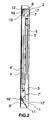
figure 2 représente le chevalet en position repliée - La
figure 3 représente en perspective l'une des deux articulations en position dépliée - La
figure 4 représente en perspective l'autre articulation en position dépliée - La
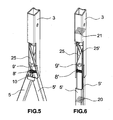
figure 5 représente les pieds en position dépliée - La
figure 6 représente les pieds en position superposée - La
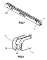
figure 7 représente la paire de traverses assemblées - La
figure 8 représente la première extrémité des traverses avant l'assemblage. - La
figure 9 représente la première extrémité des traverses après l'assemblage - La
figure 10 représente la seconde extrémité des traverses avant l'assemblage. - La
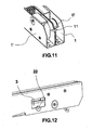
figure 11 représente la deuxième extrémité des traverses après l'assemblage - La
figure 12 représente une vue latérale des chevalets assemblés afin de montrer le système de libération des chevalets. - La
figure 13 représente une vue de l'intérieur d'un chevalet replié. - Selon la
figure 1 , le chevalet est composé d'une traverse (1), de deux articulations (2) (3), de deux paires de pieds (4) (4') et (5) (5'). Les deux articulations (2) (3) pivotent autour des axes de rotation (7) (7') perpendiculaires à la traverse (1). Les paires de pieds (4) (4') et (5) (5') pivotent autour des axes (9) (9') solidaires perpendiculairement aux articulations (2) (3). - Selon la
figure 2 , les articulations (2) (3) et les pieds (4) (4') et (5) (5') sont totalement escamotés dans le profil de la traverse (1). L'ensemble forme un profil rectangulaire et compact - Les
figures 2 et3 montrent aussi la différence entre les deux articulations (2) (3). Pour permettre une compacité accrue et la superposition des deux paires de pieds (4) (4') et (5) (5'), l'une des articulations, ici l'articulation (2), a son axe de rotation (7) désaxé par rapport au plan horizontal formé par la jonction des deux pieds (4) (4') mais reste aligné avec le second axe de rotation (7') pour garantir un verrouillage. Pour cela, la paroi de l'articulation (2) en contact avec le verrou (6) lors de l'état ouvert se situe au même niveau horizontal que la même paroi de l'articulation (3). - Selon les
figures 1 ,2 ,3 et 4 , l'utilisateur peut déployer l'articulation (3) en appuyant sur le téton (22) solidaire de l'articulation (3). Les deux articulations (2) (3) et les paires de pieds (4) (4') et (5) (5') pivotent autour des axes de rotation (7) (7') grâce à leur propre poids et viennent en butée respectivement sur (17) (17'). Le verrouillage se réalise alors par des verrous (6) (6') qui étaient logés et immobilisés sous les articulations (2) (3) en position repliée et qui sont libérés lors de la rotation des articulations (2) (3). Ce mouvement de rotation des verrous (6) (6') autour des axes (12) (12') est provoqué par les deux ressorts (19) (19') qui prennent appui sur la face intérieure et supérieure de la traverse (1) et poussent les deux verrous (6) (6'). Les points d'appuis (27) (27') des verrous (6) (6') sur les articulations (2) (3) s'alignent sur les droites horizontales symbolisées à leurs extrémités par les butées (17) (17') et les axes (12) (12'). Ces alignements confèrent aux articulations un verrouillage irréversible. Pour replier les ensembles articulations (2) (3) avec leurs pieds (4) (4') et (5) (5'), il faut alors appuyer sur les verrous (6) (6') au niveau de leurs extrémités respectives (24) (24') pour faire pivoter ces verrous (6) (6') autour de leurs axes (12) (12'). Cela permet alors la libération des articulations et leur repliage dans la traverse (1). - Les
figures 2 et3 montrent que, pour réaliser la butée en fin de course de l'articulation (2), une découpe (16) est découpée avec pour centre, l'axe de rotation (7). La fin de cette découpe (16) vient s'appuyer sur la butée (17) en position dépliée. - Selon les
figures 5 et 6 , le déploiement des pieds (4) (4') et (5) (5') se fait autour des axes (9) (9') solidaires des articulations (2) (3). Quand les articulations (2) (3) se déploient en dehors de la traverse (1), les pieds (4) (4') (5) (5') se déploient en pivotant autour des axes (9) (9') sous l'action des ressorts (8) (8'). La position finale est obtenue par les extrémités supérieures (25) (25') biseautée des pieds (4) (4') et (5) (5') viennent s'appuyer sur la paroi intérieure des articulations (2) (3). Lors du repliage, les ressorts (8) (8') s'escamotent complètement dans les pieds (4) (4') et (5) (5') permettant d'obtenir une superposition de ces derniers qui forment alors une section (20) s'inscrivant dans la section (21) définie par les articulations (2) (3). Ceci confère une compacité permettant de replier les articulations (2) (3) et les pieds (4) (4') et (5) (5') dans le profil de la traverse (1). - La
figure 7 montre les traverses (1) (1') assemblées côte à côte. - Les
figures 8 ,9 10 et11 décrivent les extrémités des traverses (1) (1'). Pour réaliser l'assemblage, l'utilisateur insère la découpe (15) de la traverse (1') dans la gouttière (14) de la traverse (1). Après avoir assemblé de la sorte ces deux extrémités des traverses (1) (1') et après avoir soulevé le crochet (11) du verrou (6'), l'utilisateur verrouille les deux autres extrémités des dites traverses (1) (1') en engageant le téton (13) de l'axe (12') du verrou (6') de la traverse (1) dans un logement (18) de la traverse (1). - Selon les
figures 2 ,10 et11 , le verrou (6') est relevé pour que le crochet (11) lié à ce verrou ne gène pas l'adossement des deux traverses (1) (1'). Quand elles arrivent en contact, le verrou (6') est relâché et poussé par le ressort (19') qui va entraîner le crochet (11), va immobiliser les deux traverses empêchant le téton (13) de ressortir du logement (18). La paire de traverses devient donc solidaire. - Les
figures 1 ,7 ,12 et13 permettent de montrer le système de libération automatique des articulations (2) (3). Un téton (22) solidaire d'un ressort (26) et coulissant dans l'articulation (3) vient dans une découpe (23) de la traverse (1). Pour libérer les pieds, l'utilisateur maintient la traverse horizontale côté ouvert vers le sol puis appuie sur le téton (22) qui s'enfonce dans l'articulation (3) et permet à cette dernière de tourner autour de l'axe de rotation (7') par la gravité.
Claims (8)
- Paire de chevalets pliants composée de deux traverses (1) (1') en forme de U qui peuvent être appariées pour former un ensemble compact et dans lesquelles sont repliés les pieds des chevalets pliants et dont l'une est munie d'une poignée pour faciliter son transport, caractérisée en ce que la traverse (1) comporte à l'une de ses extrémités une gouttière (14), un verrou (6) et à l'autre extrémité une découpe (23), un verrou (6') pourvu d'un crochet (11) et la traverse (1') comporte à l'une de ses extrémités une découpe (15) et un verrou (6') et à l'autre extrémité un téton (13) et un verrou (6) ; les traverses (1) (1') sont équipées chacune de deux articulations (2) (3) articulés en (7) (7') et dans lesquelles sont logées les extrémités supérieures (25) (25') biseautées des pieds (4) (4') et (5) (5').
- Paire de chevalets pliants selon la revendication 1 caractérisée en ce que les articulations (2) (3) pivotent chacune autour d'axes de rotation (7) (7') perpendiculaires aux traverses (1) (1').
- Paire de chevalets pliants selon les revendications 1 et 2 caractérisée en ce que, lors de son déploiement, l'articulation (3) est libérée au moyen d'un téton (22) solidaire d'un ressort (26) pendant que l'articulation (2) est libérée simultanément et automatiquement par gravité.
- Paire de chevalets pliants selon les revendications 1, 2 et 3, caractérisée en ce que les deux articulations (2) (3) comportent chacune respectivement un axe (9) (9'), perpendiculaire aux dites articulations (2) (3), autour desquels pivotent automatiquement par gravité les pieds (4) (4') et (5) (5') lors du déploiement des articulations.
- Paire de chevalets pliants selon les revendications 1, 2 et 3 caractérisée en ce que les deux articulations (2) (3) en position déployée sont automatiquement verrouillées d'une façon irréversible au moyen de ressorts (19) (19') qui entraînent des verrous (6) (6') qui pivotent autour d'axes (12) (12') de façon, d'une part à ce que les verrous (6) (6') viennent prendre appui sur les articulations (2) (3) en (27) (27') et d'autre part, en ce que les dits ressorts (19) (19') prennent appui sur la face intérieure supérieure de la traverse (1) et au moyen d'une butée (17') sur laquelle l'articulation (3) vient en appui pendant que l'articulation (2) présente une découpe (16) qui vient en appui sur la butée (17).
- Paire de chevalets pliants selon la revendication 1, caractérisée par un décalage entre le point de rotation de l'articulation (2) autour de l'axe de rotation (7) et le plan de jonction des pieds (4) (4') alors que sur l'articulation (3) ce point de rotation autour de l'axe de rotation (7') et le plan de jonction des pieds (5) (5') sont alignés horizontalement en position repliée, permettant ainsi une superposition des deux jeux de pieds (4) (4') (5) (5') et un gain de place au repliage ; chaque jeu de pieds (4) (4') et (5') (5') se superposant du fait que les axes (9) (9') intersectent l'axe de symétrie longitudinal des pieds.
- Paire de chevalets pliants selon la revendication 1, caractérisée en ce que les extrémités supérieures (25) (25') en forme biseautée des pieds (4) (4') et (5) (5') de façon à obtenir une plus grande surface d'appui des pieds sur les parois internes des articulations (2) (3) en position dépliée tout en assurant la compacité dans la position repliée.
- Paire de chevalets pliants selon la revendication 1 caractérisée en ce que les traverses (1) (1') sont appariées par l'insertion d'une découpe (15) située à l'extrémité de la traverse (1') dans une gouttière (14) solidaire de la traverse (1) et en relevant le crochet (11) solidaire du verrou (6') de la traverse (1) lorsque les traverses sont en contact, un téton (13) solidaire de l'axe (12') de la traverse (1) vient s'insérer dans un logement (18) de la traverse (1') et le verrou (6') relâché vont ensemble solidariser la paire de chevalets et faciliter son transport.
Priority Applications (5)
| Application Number | Priority Date | Filing Date | Title |
|---|---|---|---|
| ES08017592T ES2365364T3 (es) | 2008-10-07 | 2008-10-07 | Par de caballetes plegables. |
| EP08017592A EP2174756B1 (fr) | 2008-10-07 | 2008-10-07 | Paire de chevalets pliants |
| DE602008006734T DE602008006734D1 (de) | 2008-10-07 | 2008-10-07 | Paar zusammenklappbarer Stützböcke |
| AT08017592T ATE507940T1 (de) | 2008-10-07 | 2008-10-07 | Paar zusammenklappbarer stützböcke |
| PT08017592T PT2174756E (pt) | 2008-10-07 | 2008-10-07 | Par de cavaletes dobráveis |
Applications Claiming Priority (1)
| Application Number | Priority Date | Filing Date | Title |
|---|---|---|---|
| EP08017592A EP2174756B1 (fr) | 2008-10-07 | 2008-10-07 | Paire de chevalets pliants |
Publications (2)
| Publication Number | Publication Date |
|---|---|
| EP2174756A1 true EP2174756A1 (fr) | 2010-04-14 |
| EP2174756B1 EP2174756B1 (fr) | 2011-05-04 |
Family
ID=40297934
Family Applications (1)
| Application Number | Title | Priority Date | Filing Date |
|---|---|---|---|
| EP08017592A Active EP2174756B1 (fr) | 2008-10-07 | 2008-10-07 | Paire de chevalets pliants |
Country Status (5)
| Country | Link |
|---|---|
| EP (1) | EP2174756B1 (fr) |
| AT (1) | ATE507940T1 (fr) |
| DE (1) | DE602008006734D1 (fr) |
| ES (1) | ES2365364T3 (fr) |
| PT (1) | PT2174756E (fr) |
Cited By (1)
| Publication number | Priority date | Publication date | Assignee | Title |
|---|---|---|---|---|
| US11104554B2 (en) * | 2011-05-18 | 2021-08-31 | Reid Lifting Limited | Foldable gantry |
Citations (2)
| Publication number | Priority date | Publication date | Assignee | Title |
|---|---|---|---|---|
| FR2617944A1 (fr) * | 1987-07-06 | 1989-01-13 | Macc Sa | Perfectionnement aux chevalets |
| DE202006003121U1 (de) * | 2006-02-24 | 2007-07-12 | Portuleiter - Produtos Metalicos S.A. | Zusammenklappbarer Bock |
-
2008
- 2008-10-07 PT PT08017592T patent/PT2174756E/pt unknown
- 2008-10-07 AT AT08017592T patent/ATE507940T1/de active
- 2008-10-07 ES ES08017592T patent/ES2365364T3/es active Active
- 2008-10-07 DE DE602008006734T patent/DE602008006734D1/de active Active
- 2008-10-07 EP EP08017592A patent/EP2174756B1/fr active Active
Patent Citations (2)
| Publication number | Priority date | Publication date | Assignee | Title |
|---|---|---|---|---|
| FR2617944A1 (fr) * | 1987-07-06 | 1989-01-13 | Macc Sa | Perfectionnement aux chevalets |
| DE202006003121U1 (de) * | 2006-02-24 | 2007-07-12 | Portuleiter - Produtos Metalicos S.A. | Zusammenklappbarer Bock |
Cited By (1)
| Publication number | Priority date | Publication date | Assignee | Title |
|---|---|---|---|---|
| US11104554B2 (en) * | 2011-05-18 | 2021-08-31 | Reid Lifting Limited | Foldable gantry |
Also Published As
| Publication number | Publication date |
|---|---|
| PT2174756E (pt) | 2011-07-18 |
| ES2365364T3 (es) | 2011-09-30 |
| ATE507940T1 (de) | 2011-05-15 |
| DE602008006734D1 (de) | 2011-06-16 |
| EP2174756B1 (fr) | 2011-05-04 |
Similar Documents
| Publication | Publication Date | Title |
|---|---|---|
| EP3071766B1 (fr) | Structure modulaire pliable pour tente ou abris similaire à montage rapide | |
| FR2645449A1 (fr) | Chariot de golf telescopique et repliable | |
| FR2975116A1 (fr) | Echafaudage pliant | |
| FR3018536A1 (fr) | Plateforme de travail en encorbellement convertible en tour d'etaiement et utilisation | |
| EP0534843A1 (fr) | Armature pour tente rectangulaire ayant un toît à deux pans | |
| EP2599938B1 (fr) | Passerelle de sécurité à étai dépliable pour banche de coffrage | |
| EP2174756B1 (fr) | Paire de chevalets pliants | |
| FR2593542A1 (fr) | Dispositif de pied d'echafaudage pour surfaces pentues et/ou fragiles telles que de toitures | |
| EP0372284B1 (fr) | Table à tapisser, pour peintre, pliante et à dimensions variables | |
| FR2769815A1 (fr) | Lit pliant, notamment pour enfant, a pliage rapide | |
| FR2890677A1 (fr) | Plateforme individuelle de travail | |
| FR2491407A1 (fr) | Table escamotable pour vehicule, en particulier vehicule de loisir | |
| EP3978333B1 (fr) | Chariot de manutention a deplacement manuel | |
| FR2782300A3 (fr) | Table repliable pour l'amenagement interieur de vehicules | |
| EP0298263B1 (fr) | Une pair de chevalets pliables | |
| FR2934627A1 (fr) | Dispositif de positionnement et de calage d'un garde corps escamotable sur plateforme support de banches | |
| FR2666620A1 (fr) | Echelle pliante. | |
| EP0580456B1 (fr) | Echafaudage | |
| FR2606827A1 (fr) | Console et echafaudage d'echelle | |
| WO1995027836A1 (fr) | Perfectionnement aux echafaudages repliables | |
| WO2001021033A1 (fr) | Armature pliable de support de hamac | |
| FR2828522A1 (fr) | Echelle, en particulier pour caravanes autotractees et vehicules automobiles analogues | |
| FR2759265A1 (fr) | Table pliante | |
| EP1057967A1 (fr) | Escabeau ou marchepied pourvu d'une plate-forme articulée en son milieu | |
| EP4406705A1 (fr) | Servante à rouleau et/ou à billes |
Legal Events
| Date | Code | Title | Description |
|---|---|---|---|
| PUAI | Public reference made under article 153(3) epc to a published international application that has entered the european phase |
Free format text: ORIGINAL CODE: 0009012 |
|
| 17P | Request for examination filed |
Effective date: 20081009 |
|
| AK | Designated contracting states |
Kind code of ref document: A1 Designated state(s): AT BE BG CH CY CZ DE DK EE ES FI FR GB GR HR HU IE IS IT LI LT LU LV MC MT NL NO PL PT RO SE SI SK TR |
|
| AX | Request for extension of the european patent |
Extension state: AL BA MK RS |
|
| AKX | Designation fees paid |
Designated state(s): AT BE BG CH CY CZ DE DK EE ES FI FR GB GR HR HU IE IS IT LI LT LU LV MC MT NL NO PL PT RO SE SI SK TR |
|
| GRAP | Despatch of communication of intention to grant a patent |
Free format text: ORIGINAL CODE: EPIDOSNIGR1 |
|
| GRAS | Grant fee paid |
Free format text: ORIGINAL CODE: EPIDOSNIGR3 |
|
| GRAA | (expected) grant |
Free format text: ORIGINAL CODE: 0009210 |
|
| AK | Designated contracting states |
Kind code of ref document: B1 Designated state(s): AT BE BG CH CY CZ DE DK EE ES FI FR GB GR HR HU IE IS IT LI LT LU LV MC MT NL NO PL PT RO SE SI SK TR |
|
| REG | Reference to a national code |
Ref country code: GB Ref legal event code: FG4D Free format text: NOT ENGLISH |
|
| REG | Reference to a national code |
Ref country code: CH Ref legal event code: EP Ref country code: CH Ref legal event code: NV Representative=s name: KIRKER & CIE S.A. |
|
| REG | Reference to a national code |
Ref country code: IE Ref legal event code: FG4D Free format text: LANGUAGE OF EP DOCUMENT: FRENCH |
|
| REF | Corresponds to: |
Ref document number: 602008006734 Country of ref document: DE Date of ref document: 20110616 Kind code of ref document: P |
|
| REG | Reference to a national code |
Ref country code: DE Ref legal event code: R096 Ref document number: 602008006734 Country of ref document: DE Effective date: 20110616 |
|
| REG | Reference to a national code |
Ref country code: NL Ref legal event code: T3 |
|
| REG | Reference to a national code |
Ref country code: PT Ref legal event code: SC4A Free format text: AVAILABILITY OF NATIONAL TRANSLATION Effective date: 20110712 |
|
| REG | Reference to a national code |
Ref country code: ES Ref legal event code: FG2A Ref document number: 2365364 Country of ref document: ES Kind code of ref document: T3 Effective date: 20110930 |
|
| PG25 | Lapsed in a contracting state [announced via postgrant information from national office to epo] |
Ref country code: SE Free format text: LAPSE BECAUSE OF FAILURE TO SUBMIT A TRANSLATION OF THE DESCRIPTION OR TO PAY THE FEE WITHIN THE PRESCRIBED TIME-LIMIT Effective date: 20110504 Ref country code: LT Free format text: LAPSE BECAUSE OF FAILURE TO SUBMIT A TRANSLATION OF THE DESCRIPTION OR TO PAY THE FEE WITHIN THE PRESCRIBED TIME-LIMIT Effective date: 20110504 Ref country code: NO Free format text: LAPSE BECAUSE OF FAILURE TO SUBMIT A TRANSLATION OF THE DESCRIPTION OR TO PAY THE FEE WITHIN THE PRESCRIBED TIME-LIMIT Effective date: 20110804 |
|
| PG25 | Lapsed in a contracting state [announced via postgrant information from national office to epo] |
Ref country code: SI Free format text: LAPSE BECAUSE OF FAILURE TO SUBMIT A TRANSLATION OF THE DESCRIPTION OR TO PAY THE FEE WITHIN THE PRESCRIBED TIME-LIMIT Effective date: 20110504 Ref country code: GR Free format text: LAPSE BECAUSE OF FAILURE TO SUBMIT A TRANSLATION OF THE DESCRIPTION OR TO PAY THE FEE WITHIN THE PRESCRIBED TIME-LIMIT Effective date: 20110805 Ref country code: FI Free format text: LAPSE BECAUSE OF FAILURE TO SUBMIT A TRANSLATION OF THE DESCRIPTION OR TO PAY THE FEE WITHIN THE PRESCRIBED TIME-LIMIT Effective date: 20110504 Ref country code: CY Free format text: LAPSE BECAUSE OF FAILURE TO SUBMIT A TRANSLATION OF THE DESCRIPTION OR TO PAY THE FEE WITHIN THE PRESCRIBED TIME-LIMIT Effective date: 20110504 Ref country code: IS Free format text: LAPSE BECAUSE OF FAILURE TO SUBMIT A TRANSLATION OF THE DESCRIPTION OR TO PAY THE FEE WITHIN THE PRESCRIBED TIME-LIMIT Effective date: 20110904 Ref country code: LV Free format text: LAPSE BECAUSE OF FAILURE TO SUBMIT A TRANSLATION OF THE DESCRIPTION OR TO PAY THE FEE WITHIN THE PRESCRIBED TIME-LIMIT Effective date: 20110504 |
|
| REG | Reference to a national code |
Ref country code: IE Ref legal event code: FD4D |
|
| PG25 | Lapsed in a contracting state [announced via postgrant information from national office to epo] |
Ref country code: CZ Free format text: LAPSE BECAUSE OF FAILURE TO SUBMIT A TRANSLATION OF THE DESCRIPTION OR TO PAY THE FEE WITHIN THE PRESCRIBED TIME-LIMIT Effective date: 20110504 Ref country code: IE Free format text: LAPSE BECAUSE OF FAILURE TO SUBMIT A TRANSLATION OF THE DESCRIPTION OR TO PAY THE FEE WITHIN THE PRESCRIBED TIME-LIMIT Effective date: 20110504 Ref country code: EE Free format text: LAPSE BECAUSE OF FAILURE TO SUBMIT A TRANSLATION OF THE DESCRIPTION OR TO PAY THE FEE WITHIN THE PRESCRIBED TIME-LIMIT Effective date: 20110504 |
|
| PG25 | Lapsed in a contracting state [announced via postgrant information from national office to epo] |
Ref country code: DK Free format text: LAPSE BECAUSE OF FAILURE TO SUBMIT A TRANSLATION OF THE DESCRIPTION OR TO PAY THE FEE WITHIN THE PRESCRIBED TIME-LIMIT Effective date: 20110504 Ref country code: PL Free format text: LAPSE BECAUSE OF FAILURE TO SUBMIT A TRANSLATION OF THE DESCRIPTION OR TO PAY THE FEE WITHIN THE PRESCRIBED TIME-LIMIT Effective date: 20110504 Ref country code: RO Free format text: LAPSE BECAUSE OF FAILURE TO SUBMIT A TRANSLATION OF THE DESCRIPTION OR TO PAY THE FEE WITHIN THE PRESCRIBED TIME-LIMIT Effective date: 20110504 Ref country code: SK Free format text: LAPSE BECAUSE OF FAILURE TO SUBMIT A TRANSLATION OF THE DESCRIPTION OR TO PAY THE FEE WITHIN THE PRESCRIBED TIME-LIMIT Effective date: 20110504 |
|
| PLBE | No opposition filed within time limit |
Free format text: ORIGINAL CODE: 0009261 |
|
| STAA | Information on the status of an ep patent application or granted ep patent |
Free format text: STATUS: NO OPPOSITION FILED WITHIN TIME LIMIT |
|
| 26N | No opposition filed |
Effective date: 20120207 |
|
| PG25 | Lapsed in a contracting state [announced via postgrant information from national office to epo] |
Ref country code: HR Free format text: LAPSE BECAUSE OF FAILURE TO SUBMIT A TRANSLATION OF THE DESCRIPTION OR TO PAY THE FEE WITHIN THE PRESCRIBED TIME-LIMIT Effective date: 20111123 Ref country code: MC Free format text: LAPSE BECAUSE OF NON-PAYMENT OF DUE FEES Effective date: 20111031 |
|
| REG | Reference to a national code |
Ref country code: DE Ref legal event code: R097 Ref document number: 602008006734 Country of ref document: DE Effective date: 20120207 |
|
| PG25 | Lapsed in a contracting state [announced via postgrant information from national office to epo] |
Ref country code: MT Free format text: LAPSE BECAUSE OF FAILURE TO SUBMIT A TRANSLATION OF THE DESCRIPTION OR TO PAY THE FEE WITHIN THE PRESCRIBED TIME-LIMIT Effective date: 20110504 |
|
| PG25 | Lapsed in a contracting state [announced via postgrant information from national office to epo] |
Ref country code: BG Free format text: LAPSE BECAUSE OF FAILURE TO SUBMIT A TRANSLATION OF THE DESCRIPTION OR TO PAY THE FEE WITHIN THE PRESCRIBED TIME-LIMIT Effective date: 20110804 |
|
| PG25 | Lapsed in a contracting state [announced via postgrant information from national office to epo] |
Ref country code: TR Free format text: LAPSE BECAUSE OF FAILURE TO SUBMIT A TRANSLATION OF THE DESCRIPTION OR TO PAY THE FEE WITHIN THE PRESCRIBED TIME-LIMIT Effective date: 20110504 |
|
| PG25 | Lapsed in a contracting state [announced via postgrant information from national office to epo] |
Ref country code: HU Free format text: LAPSE BECAUSE OF FAILURE TO SUBMIT A TRANSLATION OF THE DESCRIPTION OR TO PAY THE FEE WITHIN THE PRESCRIBED TIME-LIMIT Effective date: 20110504 |
|
| PG25 | Lapsed in a contracting state [announced via postgrant information from national office to epo] |
Ref country code: HR Free format text: LAPSE BECAUSE OF FAILURE TO SUBMIT A TRANSLATION OF THE DESCRIPTION OR TO PAY THE FEE WITHIN THE PRESCRIBED TIME-LIMIT Effective date: 20110504 |
|
| REG | Reference to a national code |
Ref country code: FR Ref legal event code: PLFP Year of fee payment: 9 |
|
| REG | Reference to a national code |
Ref country code: FR Ref legal event code: PLFP Year of fee payment: 10 |
|
| REG | Reference to a national code |
Ref country code: FR Ref legal event code: PLFP Year of fee payment: 11 |
|
| PGFP | Annual fee paid to national office [announced via postgrant information from national office to epo] |
Ref country code: NL Payment date: 20210915 Year of fee payment: 14 |
|
| PGFP | Annual fee paid to national office [announced via postgrant information from national office to epo] |
Ref country code: PT Payment date: 20220621 Year of fee payment: 15 |
|
| REG | Reference to a national code |
Ref country code: NL Ref legal event code: MM Effective date: 20221101 |
|
| PG25 | Lapsed in a contracting state [announced via postgrant information from national office to epo] |
Ref country code: NL Free format text: LAPSE BECAUSE OF NON-PAYMENT OF DUE FEES Effective date: 20221101 |
|
| PG25 | Lapsed in a contracting state [announced via postgrant information from national office to epo] |
Ref country code: PT Free format text: LAPSE BECAUSE OF NON-PAYMENT OF DUE FEES Effective date: 20240408 |
|
| PG25 | Lapsed in a contracting state [announced via postgrant information from national office to epo] |
Ref country code: PT Free format text: LAPSE BECAUSE OF NON-PAYMENT OF DUE FEES Effective date: 20240408 |
|
| PGFP | Annual fee paid to national office [announced via postgrant information from national office to epo] |
Ref country code: FR Payment date: 20250603 Year of fee payment: 18 |
|
| PGFP | Annual fee paid to national office [announced via postgrant information from national office to epo] |
Ref country code: GB Payment date: 20250821 Year of fee payment: 18 Ref country code: BE Payment date: 20250915 Year of fee payment: 18 |
|
| REG | Reference to a national code |
Ref country code: CH Ref legal event code: U11 Free format text: ST27 STATUS EVENT CODE: U-0-0-U10-U11 (AS PROVIDED BY THE NATIONAL OFFICE) Effective date: 20251101 |
|
| PGFP | Annual fee paid to national office [announced via postgrant information from national office to epo] |
Ref country code: LU Payment date: 20251024 Year of fee payment: 18 |
|
| PGFP | Annual fee paid to national office [announced via postgrant information from national office to epo] |
Ref country code: DE Payment date: 20250908 Year of fee payment: 18 |
|
| PGFP | Annual fee paid to national office [announced via postgrant information from national office to epo] |
Ref country code: AT Payment date: 20251021 Year of fee payment: 18 |
|
| PGFP | Annual fee paid to national office [announced via postgrant information from national office to epo] |
Ref country code: IT Payment date: 20251007 Year of fee payment: 18 |
|
| PGFP | Annual fee paid to national office [announced via postgrant information from national office to epo] |
Ref country code: CH Payment date: 20251101 Year of fee payment: 18 |
|
| PGFP | Annual fee paid to national office [announced via postgrant information from national office to epo] |
Ref country code: ES Payment date: 20251114 Year of fee payment: 18 |