EP2174608A1 - Dispositif d'ancrage osseux et dispositif de stabilisation pour les éléments osseux ou vertèbres - Google Patents
Dispositif d'ancrage osseux et dispositif de stabilisation pour les éléments osseux ou vertèbres Download PDFInfo
- Publication number
- EP2174608A1 EP2174608A1 EP08017644A EP08017644A EP2174608A1 EP 2174608 A1 EP2174608 A1 EP 2174608A1 EP 08017644 A EP08017644 A EP 08017644A EP 08017644 A EP08017644 A EP 08017644A EP 2174608 A1 EP2174608 A1 EP 2174608A1
- Authority
- EP
- European Patent Office
- Prior art keywords
- rods
- bone anchoring
- bone
- receiving part
- pressure element
- Prior art date
- Legal status (The legal status is an assumption and is not a legal conclusion. Google has not performed a legal analysis and makes no representation as to the accuracy of the status listed.)
- Granted
Links
Images

Classifications
-
- A—HUMAN NECESSITIES
- A61—MEDICAL OR VETERINARY SCIENCE; HYGIENE
- A61B—DIAGNOSIS; SURGERY; IDENTIFICATION
- A61B17/00—Surgical instruments, devices or methods, e.g. tourniquets
- A61B17/56—Surgical instruments or methods for treatment of bones or joints; Devices specially adapted therefor
- A61B17/58—Surgical instruments or methods for treatment of bones or joints; Devices specially adapted therefor for osteosynthesis, e.g. bone plates, screws, setting implements or the like
- A61B17/68—Internal fixation devices, including fasteners and spinal fixators, even if a part thereof projects from the skin
- A61B17/70—Spinal positioners or stabilisers ; Bone stabilisers comprising fluid filler in an implant
- A61B17/7001—Screws or hooks combined with longitudinal elements which do not contact vertebrae
- A61B17/7035—Screws or hooks, wherein a rod-clamping part and a bone-anchoring part can pivot relative to each other
-
- A—HUMAN NECESSITIES
- A61—MEDICAL OR VETERINARY SCIENCE; HYGIENE
- A61B—DIAGNOSIS; SURGERY; IDENTIFICATION
- A61B17/00—Surgical instruments, devices or methods, e.g. tourniquets
- A61B17/56—Surgical instruments or methods for treatment of bones or joints; Devices specially adapted therefor
- A61B17/58—Surgical instruments or methods for treatment of bones or joints; Devices specially adapted therefor for osteosynthesis, e.g. bone plates, screws, setting implements or the like
- A61B17/68—Internal fixation devices, including fasteners and spinal fixators, even if a part thereof projects from the skin
- A61B17/70—Spinal positioners or stabilisers ; Bone stabilisers comprising fluid filler in an implant
- A61B17/7001—Screws or hooks combined with longitudinal elements which do not contact vertebrae
- A61B17/7002—Longitudinal elements, e.g. rods
- A61B17/7004—Longitudinal elements, e.g. rods with a cross-section which varies along its length
- A61B17/7008—Longitudinal elements, e.g. rods with a cross-section which varies along its length with parts of, or attached to, the longitudinal elements, bearing against an outside of the screw or hook heads, e.g. nuts on threaded rods
-
- A—HUMAN NECESSITIES
- A61—MEDICAL OR VETERINARY SCIENCE; HYGIENE
- A61B—DIAGNOSIS; SURGERY; IDENTIFICATION
- A61B17/00—Surgical instruments, devices or methods, e.g. tourniquets
- A61B17/56—Surgical instruments or methods for treatment of bones or joints; Devices specially adapted therefor
- A61B17/58—Surgical instruments or methods for treatment of bones or joints; Devices specially adapted therefor for osteosynthesis, e.g. bone plates, screws, setting implements or the like
- A61B17/68—Internal fixation devices, including fasteners and spinal fixators, even if a part thereof projects from the skin
- A61B17/70—Spinal positioners or stabilisers ; Bone stabilisers comprising fluid filler in an implant
- A61B17/7001—Screws or hooks combined with longitudinal elements which do not contact vertebrae
- A61B17/7002—Longitudinal elements, e.g. rods
- A61B17/7019—Longitudinal elements having flexible parts, or parts connected together, such that after implantation the elements can move relative to each other
- A61B17/702—Longitudinal elements having flexible parts, or parts connected together, such that after implantation the elements can move relative to each other having a core or insert, and a sleeve, whereby a screw or hook can move along the core or in the sleeve
-
- A—HUMAN NECESSITIES
- A61—MEDICAL OR VETERINARY SCIENCE; HYGIENE
- A61B—DIAGNOSIS; SURGERY; IDENTIFICATION
- A61B17/00—Surgical instruments, devices or methods, e.g. tourniquets
- A61B17/56—Surgical instruments or methods for treatment of bones or joints; Devices specially adapted therefor
- A61B17/58—Surgical instruments or methods for treatment of bones or joints; Devices specially adapted therefor for osteosynthesis, e.g. bone plates, screws, setting implements or the like
- A61B17/68—Internal fixation devices, including fasteners and spinal fixators, even if a part thereof projects from the skin
- A61B17/70—Spinal positioners or stabilisers ; Bone stabilisers comprising fluid filler in an implant
- A61B17/7001—Screws or hooks combined with longitudinal elements which do not contact vertebrae
- A61B17/7002—Longitudinal elements, e.g. rods
- A61B17/7019—Longitudinal elements having flexible parts, or parts connected together, such that after implantation the elements can move relative to each other
- A61B17/7031—Longitudinal elements having flexible parts, or parts connected together, such that after implantation the elements can move relative to each other made wholly or partly of flexible material
-
- A—HUMAN NECESSITIES
- A61—MEDICAL OR VETERINARY SCIENCE; HYGIENE
- A61B—DIAGNOSIS; SURGERY; IDENTIFICATION
- A61B17/00—Surgical instruments, devices or methods, e.g. tourniquets
- A61B17/56—Surgical instruments or methods for treatment of bones or joints; Devices specially adapted therefor
- A61B17/58—Surgical instruments or methods for treatment of bones or joints; Devices specially adapted therefor for osteosynthesis, e.g. bone plates, screws, setting implements or the like
- A61B17/68—Internal fixation devices, including fasteners and spinal fixators, even if a part thereof projects from the skin
- A61B17/70—Spinal positioners or stabilisers ; Bone stabilisers comprising fluid filler in an implant
- A61B17/7001—Screws or hooks combined with longitudinal elements which do not contact vertebrae
- A61B17/7032—Screws or hooks with U-shaped head or back through which longitudinal rods pass
-
- A—HUMAN NECESSITIES
- A61—MEDICAL OR VETERINARY SCIENCE; HYGIENE
- A61B—DIAGNOSIS; SURGERY; IDENTIFICATION
- A61B17/00—Surgical instruments, devices or methods, e.g. tourniquets
- A61B17/56—Surgical instruments or methods for treatment of bones or joints; Devices specially adapted therefor
- A61B17/58—Surgical instruments or methods for treatment of bones or joints; Devices specially adapted therefor for osteosynthesis, e.g. bone plates, screws, setting implements or the like
- A61B17/68—Internal fixation devices, including fasteners and spinal fixators, even if a part thereof projects from the skin
- A61B17/70—Spinal positioners or stabilisers ; Bone stabilisers comprising fluid filler in an implant
- A61B17/7001—Screws or hooks combined with longitudinal elements which do not contact vertebrae
- A61B17/7035—Screws or hooks, wherein a rod-clamping part and a bone-anchoring part can pivot relative to each other
- A61B17/7037—Screws or hooks, wherein a rod-clamping part and a bone-anchoring part can pivot relative to each other wherein pivoting is blocked when the rod is clamped
-
- A—HUMAN NECESSITIES
- A61—MEDICAL OR VETERINARY SCIENCE; HYGIENE
- A61B—DIAGNOSIS; SURGERY; IDENTIFICATION
- A61B17/00—Surgical instruments, devices or methods, e.g. tourniquets
- A61B17/56—Surgical instruments or methods for treatment of bones or joints; Devices specially adapted therefor
- A61B17/58—Surgical instruments or methods for treatment of bones or joints; Devices specially adapted therefor for osteosynthesis, e.g. bone plates, screws, setting implements or the like
- A61B17/68—Internal fixation devices, including fasteners and spinal fixators, even if a part thereof projects from the skin
- A61B17/70—Spinal positioners or stabilisers ; Bone stabilisers comprising fluid filler in an implant
- A61B17/7001—Screws or hooks combined with longitudinal elements which do not contact vertebrae
- A61B17/7046—Screws or hooks combined with longitudinal elements which do not contact vertebrae the screws or hooks being mobile in use relative to the longitudinal element
-
- A—HUMAN NECESSITIES
- A61—MEDICAL OR VETERINARY SCIENCE; HYGIENE
- A61B—DIAGNOSIS; SURGERY; IDENTIFICATION
- A61B17/00—Surgical instruments, devices or methods, e.g. tourniquets
- A61B17/56—Surgical instruments or methods for treatment of bones or joints; Devices specially adapted therefor
- A61B17/58—Surgical instruments or methods for treatment of bones or joints; Devices specially adapted therefor for osteosynthesis, e.g. bone plates, screws, setting implements or the like
- A61B17/68—Internal fixation devices, including fasteners and spinal fixators, even if a part thereof projects from the skin
- A61B17/70—Spinal positioners or stabilisers ; Bone stabilisers comprising fluid filler in an implant
- A61B17/7049—Connectors, not bearing on the vertebrae, for linking longitudinal elements together
-
- A—HUMAN NECESSITIES
- A61—MEDICAL OR VETERINARY SCIENCE; HYGIENE
- A61B—DIAGNOSIS; SURGERY; IDENTIFICATION
- A61B17/00—Surgical instruments, devices or methods, e.g. tourniquets
- A61B2017/00831—Material properties
- A61B2017/0084—Material properties low friction
- A61B2017/00845—Material properties low friction of moving parts with respect to each other
Definitions
- the invention relates to a bone anchoring device, in particular to a polyaxial bone screw which is connected to two stabilization rods and to a stabilization device comprising such a bone anchoring device, in particular for the stabilization of the spinal column.
- the stabilization device comprises two bone anchoring elements at least one of which is a polyaxial bone screw and a rigid rod with a longitudinal axis connecting them.
- An elastic element is inserted between the two bone anchoring elements. It acts on the bone anchoring elements to exert a force in a direction of the longitudinal axis.
- One of the bone anchoring elements is fixedly connected to the rod to prevent translational movement of the rod and the other bone anchoring element is slidably connected to the rod.
- EP 1 800 614 A1 describes a dynamic stabilization device for bones or for vertebrae comprising at least two bone anchoring elements and at least one connection element in form of an elastic loop connecting the bone anchoring elements.
- the bone anchoring element is in the form of a polyaxial bone screw the receiving part of which accommodates to two elastic loops each of which can be connected to a second bone anchoring element.
- a modular double-rod i.e. two rods
- each rod can be designed smaller than a single rod.
- the low profile cross-section of two rods compared to one single rod has also the advantage that the stiffness of the rods is enhanced.
- the stability in view of bending or torsional loads of the double-rod system is also enhanced.
- the dynamic properties of the stabilization device can be adjusted by selecting appropriate rods and/or adjusting the sliding motion of the rods by stops and/or damping elements.
- the dynamic properties of the rods can vary.
- the rods can have the same or different elastic properties. They can be made of the same or different material.
- the stabilization device comprises a first polyaxial pedicle screws 1, a second pedicle screw 2 and two rods 3a, 3b connecting them for stabilizing two adjacent vertebrae.
- each rod a spring element 4a, 4b is provided and the rods 3a, 3b are connected by rod connectors 5, 6.
- the rods 3a, 3b are fixedly clamped in the second pedicle screw 2 and can slide through the first pedicle screw 1 as shown by the arrows.
- the sliding motion is limited by means of the rod connector 6 which connects the free ends of the rods 3a, 3b and acts as a stop.
- the springs 4a, 4b and the rod connector 5 limit the sliding motion of the rods 3a, 3b relative to the first pedicle screw 1 in the direction of the second pedicle screw 2.
- the springs provide elastic damping.
- the rod connectors 5, 6 are sleeve shaped with two channels 5a, 5b, 6a, 6b, respectively, for guiding through the rods 3a, 3b.
- the distance of the channels corresponds to the distance of the rods in which they are guided through the pedicle screws.
- the rod connectors 5, 6 connect the rod 3a, 3b by means of a press-fit connection i.e the diameter of the channels is selected such that the rods are firmly connected.
- the rod connectors 5, 6 can be made of an elastomer material or any other body compatible material.
- the springs 4a, 4b in this embodiment are shown as helical springs encompassing the rods 3a, 3b like sleeves. They can be made of any body compatible material, in particular of titanium, nickel titanium alloys, for example nitinol, or other materials.
- the rods 3a, 3b exhibit a flexibility under forces having a component perpendicular to the rod axis, such as bending forces.
- the rods are made of non-compressible materials, such as stainless steel, titanium, nickel titanium alloys, such as nitinol, PEEK or carbon reinforced PEEK or other body compatible materials.
- rod connectors and the springs are only examples for the function of connecting the two rods, providing a stop and providing a damping to the sliding motion.
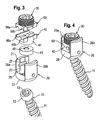
- the pedicle screw 1 comprises a screw element 10 with a threaded shank 11 and a spherically segment-shaped head 12. At the free end of the head 12 a recess 13 is provided for engagement with a tool.
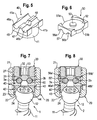
- the pedicle screw 1 further comprises a receiving part 20 with a first end 21 and a second 22 and a coaxial bore 23 extending from the first end in the direction of the second end. At the second end 22 the bore 23 tapers to provide an opening and a seat 24 for the screw head 12 as shown in particular in Fig. 7 .
- the receiving part 20 further comprises a recess 25 extending from the first end 21 in the direction of the second end 22 which provides a channel through the receiving part in a direction perpendicular to the bore axis of bore 23 for guiding through the rods 3a, 3b.
- a recess 25 extending from the first end 21 in the direction of the second end 22 which provides a channel through the receiving part in a direction perpendicular to the bore axis of bore 23 for guiding through the rods 3a, 3b.
- two free legs 26a, 26b are provided. Near the first end 21 the free legs 26a, 26b have an internal thread 27 for cooperation with a fixation screw 30.
- the screw element 10 and the receiving part 20 as well as the fixation screw 30 are made of a rigid body compatible material, such as a body compatible metal like stainless steel or titanium or a titanium alloy, such as nitinol.
- the first pressure element 40 and the second pressure element 50 also form guiding elements for guiding the rods 3a, 3b through the receiving part 20.
- the first pressure element 40 has a substantially cylindrical body part 41 which is sized such that the first pressure element 40 can be inserted in the receiving part and moved in an axial direction within the bore 23.
- the first pressure element 40 comprises a cylindrical recess 42 shown in Fig. 7 in which a cylindrical insert 43 is provided.
- the insert 43 has on its side facing the head 12 of the screw element a spherical recess 44 the radius of which fits to the radius of spherical head 12 of the screw element.
- the first pressure element 40 further comprises a cuboid body part 45 which is shaped so as to fit in the recess 25 of the receiving part 20 as shown in particular in Figs. 3 and 4 .
- the width of the rectangle corresponds to the width of the recess 25 and the length is selected such that the first pressure element is flush with the outer surface 28 of the receiving part 20 as shown in Fig. 4 .
- the cuboid body part On its side opposite to the recess 42 the cuboid body part comprises two cylinder segment-shaped recesses 46a, 46b the cylinder radius of which is slightly larger than the radius of the rods 3a, 3b.
- the recesses 46a, 46b extend perpendicular to the axis of the coaxial bore 23 of the receiving part 20.
- the first pressure element 40 also has a coaxial bore 48 for providing access to the head 12 of the screw element with a tool.
- the cylindrical insert 43 has a coaxial bore 49.
- the cylindrical body part 41 and the cuboid body part 25 are shown to be made in one piece so that cylindrical segment-shaped flanges 41 a, 41b are provided on each side of the channel 46a, 46b. The flanges facilitate the guidance of the first pressure element 40 within the receiving part 20.
- the cuboid body part 45 prevents rotation of the first pressure element within the receiving part once the first pressure element is inserted into the recess 25.
- the second pressure element 50 is substantially cuboid shaped with a width and length corresponding to that of the cuboid body part 45 of the first pressure element 40. Therefore, it also fits into the recess 25 of the receiving part. On its long sides it comprises two cylindrical segment-shaped flanges 51a, 51b corresponding to the flanges 41a, 41b of the first pressure element. On its side opposite to the first pressure element 40, the second pressure element 50 comprises a cylindrical recess 52 and a coaxial cylindrical projection 53 in which a corresponding ring-shaped projection 31 and a cylindrical recess 32 of the fixation screw 30 engage, as shown in Fig. 7 . Thereby, the fixation screw 30 can be rotatably connected to the pressure element 50.
- the second pressure element 50 On its side facing the first pressure element, the second pressure element 50 comprises two longitudinal cylinder segment-shaped recesses 56a, 56b which are complementary in their size and distance to the channels 46a, 46b of the first pressure element.
- the channels 56a, 56b are spaced apart by a rib 57.
- the first pressure element presses via the insert 43 onto the head 12.
- the second pressure element 50 presses onto the first pressure element 40 thereby providing closed channels for the rods 3a, 3b which are accomodated therein with a gap 60 to the wall of the channel. Since the fixation screw 30 is rotatably connected to the second pressure element, the fixation screw 30 can be tightened when the second pressure element 50 is inserted.
- the first pressure element and the second pressure element can be made of a material which facilitates sliding of the rods 3a, 3b.
- the pressure elements can be made of titanium or a nickel titanium alloy which is coated or of PEEK or carbon reinforced PEEK.
- the insert 43 is preferably made of the same material as the head 12 of the screw, for example of a body compatible metal.
- the first pressure element itself can have a spherical recess to press onto the head.
- the rods 3a, 3b themselves can have a surface which facilitates sliding, for example a coated or otherwise treated surface.
- the second pedicle screw 2 shown in Figs. 1, 2 and 8 differs from the first pedicle screw 1 in the design of the first and second pressure elements. All other parts are identical and have the same reference numerals. Therefore, the description thereof is not repeated.
- the shape of the first pressure element 40' and of the second pressure element 50' of the second pedicle screw 2 is the same as that of the first pressure element 40 and the second pressure element 50 of the first pedicle screw 1.
- the size of the channels 46a', 46b', 56a', 56b' is smaller than that of the channels of the first and second pressure element of the first pedicle screw.
- the radius of the channels is adapted to the radius of the rods 3a, 3b and depth of the channels is smaller than the radius of the rods 3a, 3b such that, as shown in Fig. 8 , in the assembled state the rods 3a, 3b are clamped between the first pressure element 40' and the second pressure element 50'.
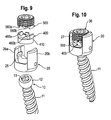
- a second embodiment of the stabilization device is shown in Figs. 9 and 10 without the rods.
- the second embodiment differs from the first embodiment described with reference to Figs. 1 to 8 only in the shape of the first and second pressure elements 400, 500.
- the length of the channels 460a, 460b is smaller than the diameter of the cylindrical body part 410. Therefore, the first pressure element 400 and the second pressure element 500 are arranged completely within the cylindrical bore 23 of the receiving part.
- the pedicle screws and the design of the pressure elements can be such that more than two rods can be accommodated. It is possible to use rods with different elastic properties. It is sufficient, if one of the pressure elements has the channels for guiding the rods, however, it is advantageous if the rods are guided from below and from the top by the channels.
- the shape of the lower part of the first pressure element can be flat, however, a shape adapted to the shape of the head of the screw 12 is advantageous for distributing the pressure onto the head.
- the fixation element can be a two-part fixation screw wherein the first screw element of a bushing type presses onto the first pressure element for locking of the head 12 and a second screw element of a set screw type arranged within the first screw element presses onto the second pressure element for fixation of the rods in the embodiment shown in Fig. 8 .
- the receiving part can be shaped as a top loader as shown in the figures or a bottom loader in which the screw element 10 is introduced from the bottom, i.e. the second end of the receiving part.
- the shank of the screw element does not have to have a thread. It can be in the form of a hook, a nail or can have barb elements for anchoring in the bone.
- the springs can be also provided adjacent the outer stop 6. It is also conceivable that the rods themselves have an axial elastic spring portion.
- the screw elements of the pedicle screws 1, 2 which have been inserted into the receiving parts 20 are screwed into adjacent vertebrae.
- the first pressure elements can be preassembled so that after alignment of the receiving parts the rods 3a, 3b can be inserted into the receiving parts and the channels of the first pressure element, respectively.
- the rods 3a, 3b with the stops and the springs can be preassembled as well and can be inserted as a double-rod system.
- the first pedicle screw and the stop 6 points in the direction the patient's head.
- the arrangement of the pedicle screws depends on the specific clinical situation.
- the angular position of the screw elements relative to the receiving parts is fixed by inserting the fixation screw together with the second pressure element and tightening the fixation screw.
- the rods 3a, 3b are fixed simultaneously with the screw head 12.
- the head 12 of the screw element is fixed while the rods can still slide within the channels.
- the rods can slide through the receiving part of the first pedicle screw during flexion or extension of the spinal motion segment, whereby the sliding movement is limited by the rod connectors 6 and 5 acting as stops and dampened by the springs 4a, 4b. Simultaneously, the rods may experience bending forces and can bend to some extend provided by the flexibility of the material of the rods.
Priority Applications (8)
| Application Number | Priority Date | Filing Date | Title |
|---|---|---|---|
| EP08017644A EP2174608B1 (fr) | 2008-10-08 | 2008-10-08 | Dispositif d'ancrage osseux et dispositif de stabilisation pour les éléments osseux ou vertèbres |
| ES08017644T ES2392362T3 (es) | 2008-10-08 | 2008-10-08 | Dispositivo de anclaje de huesos y dispositivo de estabilización para partes de hueso o vértebras |
| CN200910204457.3A CN101716096B (zh) | 2008-10-08 | 2009-09-29 | 骨部分或椎骨用骨锚固装置及包括该骨锚固装置的稳定装置 |
| US12/571,299 US8795336B2 (en) | 2008-10-08 | 2009-09-30 | Bone anchoring device and stabilization device for bone parts or vertebrae comprising such a bone anchoring device |
| KR1020090094313A KR20100039809A (ko) | 2008-10-08 | 2009-10-05 | 뼈 고정 장치 및 상기 장치를 구비한 뼈 부분 또는 척추뼈를 안정화시키기 위한 안정화 장치 |
| JP2009231669A JP2010088887A (ja) | 2008-10-08 | 2009-10-05 | 骨固定装置、および、その骨固定装置を備えた骨の部分または椎骨を安定化するための安定化装置 |
| TW098133655A TW201014562A (en) | 2008-10-08 | 2009-10-05 | Bone anchoring device and stabilization device for bone parts or vertebrae comprising such a bone anchoring device |
| US14/315,684 US20140379031A1 (en) | 2008-10-08 | 2014-06-26 | Bone anchoring device and stabilization device for bone parts or vertebrae comprising such a bone anchoring device |
Applications Claiming Priority (1)
| Application Number | Priority Date | Filing Date | Title |
|---|---|---|---|
| EP08017644A EP2174608B1 (fr) | 2008-10-08 | 2008-10-08 | Dispositif d'ancrage osseux et dispositif de stabilisation pour les éléments osseux ou vertèbres |
Publications (2)
| Publication Number | Publication Date |
|---|---|
| EP2174608A1 true EP2174608A1 (fr) | 2010-04-14 |
| EP2174608B1 EP2174608B1 (fr) | 2012-08-01 |
Family
ID=40212895
Family Applications (1)
| Application Number | Title | Priority Date | Filing Date |
|---|---|---|---|
| EP08017644A Not-in-force EP2174608B1 (fr) | 2008-10-08 | 2008-10-08 | Dispositif d'ancrage osseux et dispositif de stabilisation pour les éléments osseux ou vertèbres |
Country Status (7)
| Country | Link |
|---|---|
| US (2) | US8795336B2 (fr) |
| EP (1) | EP2174608B1 (fr) |
| JP (1) | JP2010088887A (fr) |
| KR (1) | KR20100039809A (fr) |
| CN (1) | CN101716096B (fr) |
| ES (1) | ES2392362T3 (fr) |
| TW (1) | TW201014562A (fr) |
Cited By (7)
| Publication number | Priority date | Publication date | Assignee | Title |
|---|---|---|---|---|
| EP2505155A1 (fr) * | 2011-03-31 | 2012-10-03 | Spinelab AG | Implant de colonne vertébrale pour la stabilisation et le raidissement de vertèbres d'une colonne vertébrale |
| WO2012076005A3 (fr) * | 2010-12-08 | 2012-10-04 | Aces Gmbh | Dispositif d'ancrage osseux dynamique |
| EP2826429A1 (fr) * | 2013-07-19 | 2015-01-21 | Biedermann Technologies GmbH & Co. KG | Dispositif d'ancrage d'os polyaxial |
| EP3100693A1 (fr) * | 2015-06-04 | 2016-12-07 | Zimmer Spine | Système de stabilisation dynamique |
| FR3073731A1 (fr) * | 2017-11-22 | 2019-05-24 | Hassan Razian | Systeme pour relier deux portions d'os entre elles quand l'une doit se deplacer par rapport a l'autre |
| FR3106968A1 (fr) * | 2020-02-06 | 2021-08-13 | Hassan Razian | Système pour relier entre elles au moins deux portions d’os |
| EP3991673A1 (fr) * | 2020-10-29 | 2022-05-04 | Biedermann Technologies GmbH & Co. KG | Dispositif de couplage d'une tige sur un ancrage osseux |
Families Citing this family (78)
| Publication number | Priority date | Publication date | Assignee | Title |
|---|---|---|---|---|
| US7833250B2 (en) | 2004-11-10 | 2010-11-16 | Jackson Roger P | Polyaxial bone screw with helically wound capture connection |
| US10729469B2 (en) | 2006-01-09 | 2020-08-04 | Roger P. Jackson | Flexible spinal stabilization assembly with spacer having off-axis core member |
| US8353932B2 (en) | 2005-09-30 | 2013-01-15 | Jackson Roger P | Polyaxial bone anchor assembly with one-piece closure, pressure insert and plastic elongate member |
| US10258382B2 (en) | 2007-01-18 | 2019-04-16 | Roger P. Jackson | Rod-cord dynamic connection assemblies with slidable bone anchor attachment members along the cord |
| US8292926B2 (en) | 2005-09-30 | 2012-10-23 | Jackson Roger P | Dynamic stabilization connecting member with elastic core and outer sleeve |
| US7862587B2 (en) | 2004-02-27 | 2011-01-04 | Jackson Roger P | Dynamic stabilization assemblies, tool set and method |
| US8876868B2 (en) | 2002-09-06 | 2014-11-04 | Roger P. Jackson | Helical guide and advancement flange with radially loaded lip |
| US7621918B2 (en) | 2004-11-23 | 2009-11-24 | Jackson Roger P | Spinal fixation tool set and method |
| US7377923B2 (en) | 2003-05-22 | 2008-05-27 | Alphatec Spine, Inc. | Variable angle spinal screw assembly |
| US8926670B2 (en) | 2003-06-18 | 2015-01-06 | Roger P. Jackson | Polyaxial bone screw assembly |
| US7776067B2 (en) | 2005-05-27 | 2010-08-17 | Jackson Roger P | Polyaxial bone screw with shank articulation pressure insert and method |
| US7766915B2 (en) | 2004-02-27 | 2010-08-03 | Jackson Roger P | Dynamic fixation assemblies with inner core and outer coil-like member |
| US8366753B2 (en) | 2003-06-18 | 2013-02-05 | Jackson Roger P | Polyaxial bone screw assembly with fixed retaining structure |
| US11419642B2 (en) | 2003-12-16 | 2022-08-23 | Medos International Sarl | Percutaneous access devices and bone anchor assemblies |
| US7527638B2 (en) | 2003-12-16 | 2009-05-05 | Depuy Spine, Inc. | Methods and devices for minimally invasive spinal fixation element placement |
| US7179261B2 (en) | 2003-12-16 | 2007-02-20 | Depuy Spine, Inc. | Percutaneous access devices and bone anchor assemblies |
| US9050148B2 (en) | 2004-02-27 | 2015-06-09 | Roger P. Jackson | Spinal fixation tool attachment structure |
| JP2007525274A (ja) | 2004-02-27 | 2007-09-06 | ロジャー・ピー・ジャクソン | 整形外科インプラントロッド整復器具セット及び方法 |
| US7160300B2 (en) | 2004-02-27 | 2007-01-09 | Jackson Roger P | Orthopedic implant rod reduction tool set and method |
| US8152810B2 (en) | 2004-11-23 | 2012-04-10 | Jackson Roger P | Spinal fixation tool set and method |
| US11241261B2 (en) | 2005-09-30 | 2022-02-08 | Roger P Jackson | Apparatus and method for soft spinal stabilization using a tensionable cord and releasable end structure |
| US8066739B2 (en) | 2004-02-27 | 2011-11-29 | Jackson Roger P | Tool system for dynamic spinal implants |
| US7651502B2 (en) | 2004-09-24 | 2010-01-26 | Jackson Roger P | Spinal fixation tool set and method for rod reduction and fastener insertion |
| US8926672B2 (en) | 2004-11-10 | 2015-01-06 | Roger P. Jackson | Splay control closure for open bone anchor |
| US8444681B2 (en) | 2009-06-15 | 2013-05-21 | Roger P. Jackson | Polyaxial bone anchor with pop-on shank, friction fit retainer and winged insert |
| US8308782B2 (en) | 2004-11-23 | 2012-11-13 | Jackson Roger P | Bone anchors with longitudinal connecting member engaging inserts and closures for fixation and optional angulation |
| US9980753B2 (en) | 2009-06-15 | 2018-05-29 | Roger P Jackson | pivotal anchor with snap-in-place insert having rotation blocking extensions |
| US9216041B2 (en) * | 2009-06-15 | 2015-12-22 | Roger P. Jackson | Spinal connecting members with tensioned cords and rigid sleeves for engaging compression inserts |
| US9168069B2 (en) | 2009-06-15 | 2015-10-27 | Roger P. Jackson | Polyaxial bone anchor with pop-on shank and winged insert with lower skirt for engaging a friction fit retainer |
| US7901437B2 (en) | 2007-01-26 | 2011-03-08 | Jackson Roger P | Dynamic stabilization member with molded connection |
| US8105368B2 (en) | 2005-09-30 | 2012-01-31 | Jackson Roger P | Dynamic stabilization connecting member with slitted core and outer sleeve |
| US8475498B2 (en) | 2007-01-18 | 2013-07-02 | Roger P. Jackson | Dynamic stabilization connecting member with cord connection |
| US8366745B2 (en) | 2007-05-01 | 2013-02-05 | Jackson Roger P | Dynamic stabilization assembly having pre-compressed spacers with differential displacements |
| US10792074B2 (en) | 2007-01-22 | 2020-10-06 | Roger P. Jackson | Pivotal bone anchor assemly with twist-in-place friction fit insert |
| US10383660B2 (en) | 2007-05-01 | 2019-08-20 | Roger P. Jackson | Soft stabilization assemblies with pretensioned cords |
| US20090105756A1 (en) | 2007-10-23 | 2009-04-23 | Marc Richelsoph | Spinal implant |
| US8784453B1 (en) | 2008-06-09 | 2014-07-22 | Melvin Law | Dynamic spinal stabilization system |
| US8043340B1 (en) | 2008-06-09 | 2011-10-25 | Melvin Law | Dynamic spinal stabilization system |
| EP2442739A1 (fr) | 2008-08-01 | 2012-04-25 | Jackson, Roger P. | Élément longitudinal de liaison avec cordons tendus gainés |
| EP2160989B1 (fr) * | 2008-09-05 | 2012-05-02 | BIEDERMANN MOTECH GmbH | Dispositif de stabilisation pour os, en particulier pour la colonne vertébrale |
| US9603629B2 (en) * | 2008-09-09 | 2017-03-28 | Intelligent Implant Systems Llc | Polyaxial screw assembly |
| GB2465156B (en) * | 2008-11-05 | 2012-09-26 | Dalmatic Lystrup As | Bone fixation system |
| US8998959B2 (en) | 2009-06-15 | 2015-04-07 | Roger P Jackson | Polyaxial bone anchors with pop-on shank, fully constrained friction fit retainer and lock and release insert |
| CN103917181A (zh) | 2009-06-15 | 2014-07-09 | 罗杰.P.杰克逊 | 包括套接杆和具有低外形边缘锁的摩擦配合保持件的多轴骨锚 |
| US11229457B2 (en) | 2009-06-15 | 2022-01-25 | Roger P. Jackson | Pivotal bone anchor assembly with insert tool deployment |
| US9668771B2 (en) | 2009-06-15 | 2017-06-06 | Roger P Jackson | Soft stabilization assemblies with off-set connector |
| CN103826560A (zh) | 2009-06-15 | 2014-05-28 | 罗杰.P.杰克逊 | 具有套接杆和带摩擦配合压缩套爪的带翼插件的多轴骨锚 |
| US11464549B2 (en) | 2009-06-15 | 2022-10-11 | Roger P. Jackson | Pivotal bone anchor assembly with horizontal tool engagement grooves and insert with upright arms having flared outer portions |
| AU2010303934B2 (en) | 2009-10-05 | 2014-03-27 | Roger P. Jackson | Polyaxial bone anchor with non-pivotable retainer and pop-on shank, some with friction fit |
| US20230404629A1 (en) * | 2010-05-14 | 2023-12-21 | Roger P. Jackson | Pivotal bone anchor assembly and method for use thereof |
| US9113960B2 (en) * | 2010-06-08 | 2015-08-25 | Globus Medical, Inc. | Conforming bone stabilization receiver |
| WO2012033532A1 (fr) | 2010-09-08 | 2012-03-15 | Roger Jackson P | Membres de stabilisation dynamiques dotés de sections élastiques et non élastiques |
| EP2635212A4 (fr) | 2010-11-02 | 2013-11-20 | Jackson Roger P | Dispositif polyaxial d'ancrage osseux à tige fixée par pression et à élément de retenue pivotant |
| JP5865479B2 (ja) | 2011-03-24 | 2016-02-17 | ロジャー・ピー・ジャクソン | 複合関節とポップ装着式シャンクとを有する多軸の骨アンカー |
| EP2747670A4 (fr) | 2011-10-05 | 2015-06-24 | Mark A Dodson | Ecarteur modulaire et procédé associé |
| US8911479B2 (en) | 2012-01-10 | 2014-12-16 | Roger P. Jackson | Multi-start closures for open implants |
| CN103356275B (zh) * | 2012-03-29 | 2016-06-01 | 董健文 | 一种微动腰椎椎弓根钉棒弹性固定系统 |
| US8911478B2 (en) | 2012-11-21 | 2014-12-16 | Roger P. Jackson | Splay control closure for open bone anchor |
| US10058354B2 (en) | 2013-01-28 | 2018-08-28 | Roger P. Jackson | Pivotal bone anchor assembly with frictional shank head seating surfaces |
| US8852239B2 (en) | 2013-02-15 | 2014-10-07 | Roger P Jackson | Sagittal angle screw with integral shank and receiver |
| US9044273B2 (en) | 2013-10-07 | 2015-06-02 | Intelligent Implant Systems, Llc | Polyaxial plate rod system and surgical procedure |
| US9566092B2 (en) | 2013-10-29 | 2017-02-14 | Roger P. Jackson | Cervical bone anchor with collet retainer and outer locking sleeve |
| US9717533B2 (en) | 2013-12-12 | 2017-08-01 | Roger P. Jackson | Bone anchor closure pivot-splay control flange form guide and advancement structure |
| US9451993B2 (en) | 2014-01-09 | 2016-09-27 | Roger P. Jackson | Bi-radial pop-on cervical bone anchor |
| EP2939638B1 (fr) * | 2014-04-30 | 2018-04-11 | Zimmer GmbH | Ensemble pour connecter un ensemble prothétique d'une articulation artificielle à un os |
| US10064658B2 (en) | 2014-06-04 | 2018-09-04 | Roger P. Jackson | Polyaxial bone anchor with insert guides |
| US9597119B2 (en) * | 2014-06-04 | 2017-03-21 | Roger P. Jackson | Polyaxial bone anchor with polymer sleeve |
| US9949763B2 (en) * | 2014-06-13 | 2018-04-24 | Warsaw Orthopedic, Inc. | Bone fastener and methods of use |
| CN105078562A (zh) * | 2015-03-13 | 2015-11-25 | 上海三友医疗器械有限公司 | 一种带有连接器的医用螺钉 |
| JP6892993B2 (ja) * | 2016-01-22 | 2021-06-23 | 京セラ株式会社 | 脊椎用スクリューアセンブリ |
| EP3592227B1 (fr) * | 2017-03-10 | 2022-03-02 | University of Washington | Procédés et systèmes pour mesurer et évaluer la stabilité d'implants médicaux |
| WO2020102787A1 (fr) | 2018-11-16 | 2020-05-22 | Surber, James L. | Ensemble ancrage osseux pivotant ayant un insert de douille de serrage déployable avec bague de pression interne |
| WO2020132571A1 (fr) | 2018-12-21 | 2020-06-25 | Paradigm Spine, Llc | Système modulaire de stabilisation de colonne vertébrale et instruments associés |
| US20200390472A1 (en) * | 2019-02-27 | 2020-12-17 | Orthopediatrics Corp. | Bone anchor with cord retention features |
| US20200323562A1 (en) * | 2019-04-12 | 2020-10-15 | Orthopediatrics Corp. | Dual tether support of vertebra |
| US11337734B2 (en) | 2019-05-22 | 2022-05-24 | Nuvasive, Inc. | Posterior spinal fixation screws |
| US11723691B2 (en) * | 2019-12-25 | 2023-08-15 | Apifix Ltd | Biasing device for spinal device |
| US20220110661A1 (en) * | 2020-10-12 | 2022-04-14 | Globus Medical, Inc. | Scoliosis correction systems, methods, and instruments |
Citations (10)
| Publication number | Priority date | Publication date | Assignee | Title |
|---|---|---|---|---|
| US5797911A (en) * | 1996-09-24 | 1998-08-25 | Sdgi Holdings, Inc. | Multi-axial bone screw assembly |
| US6206879B1 (en) * | 1998-10-22 | 2001-03-27 | Aesculap Ag & Co. Kg | Osteosynthetic holding system |
| WO2003034930A1 (fr) * | 2001-10-23 | 2003-05-01 | Biedermann Motech Gmbh | Dispositif de fixation osseuse et vis associee |
| US20040049190A1 (en) | 2002-08-09 | 2004-03-11 | Biedermann Motech Gmbh | Dynamic stabilization device for bones, in particular for vertebrae |
| US20040111088A1 (en) * | 2002-12-06 | 2004-06-10 | Picetti George D. | Multi-rod bone attachment member |
| FR2863860A1 (fr) * | 2003-12-17 | 2005-06-24 | Sdgi Holdings Inc | Dispositif d'osteosynthese du rachis. |
| US20050171537A1 (en) * | 2001-11-27 | 2005-08-04 | Christian Mazel | Connector for vertebral anchoring system |
| EP1800614A1 (fr) | 2005-12-23 | 2007-06-27 | BIEDERMANN MOTECH GmbH | Dispositif de stabilisation dynamique d'os ou de vertèbres |
| EP1800613A1 (fr) * | 2005-12-23 | 2007-06-27 | BIEDERMANN MOTECH GmbH | Dispositif souple de stabilisation pour stabiliser dynamiquement des os ou des vertèbres |
| WO2008036578A2 (fr) * | 2006-09-18 | 2008-03-27 | Warsaw Orthopedic, Inc | Système de plaque orthopédique |
Family Cites Families (73)
| Publication number | Priority date | Publication date | Assignee | Title |
|---|---|---|---|---|
| GB1519139A (en) * | 1974-06-18 | 1978-07-26 | Crock H V And Pericic L | L securing elongate members to structurs more especially in surgical procedures |
| FR2689750B1 (fr) * | 1992-04-10 | 1997-01-31 | Eurosurgical | Element d'ancrage osseux et dispositif d'osteosynthese rachidienne incorporant de tels elements. |
| FR2697992B1 (fr) * | 1992-11-18 | 1994-12-30 | Eurosurgical | Dispositif de fixation sur une tige d'un organe, en particulier pour une instrumentation d'orthopédie rachidienne. |
| US6413257B1 (en) * | 1997-05-15 | 2002-07-02 | Surgical Dynamics, Inc. | Clamping connector for spinal fixation systems |
| US6302888B1 (en) * | 1999-03-19 | 2001-10-16 | Interpore Cross International | Locking dovetail and self-limiting set screw assembly for a spinal stabilization member |
| ES2240384T3 (es) * | 2000-09-18 | 2005-10-16 | Zimmer Gmbh | Tornillo pedicular para elemento de soporte intervertebral. |
| FR2829014B1 (fr) * | 2001-09-03 | 2005-04-08 | Stryker Spine | Systeme d'osteosynthese rachidienne comprenant un patin d'appui |
| US6793657B2 (en) * | 2001-09-10 | 2004-09-21 | Solco Biomedical Co., Ltd. | Spine fixing apparatus |
| FR2831048B1 (fr) * | 2001-10-18 | 2004-09-17 | Ldr Medical | Dispositif d'osteosynthese a approche progressive et procede de premontage |
| FR2831049B1 (fr) * | 2001-10-18 | 2004-08-13 | Ldr Medical | Plaque pour dispositif d'osteosynthese et procede de premontage |
| US6783527B2 (en) * | 2001-10-30 | 2004-08-31 | Sdgi Holdings, Inc. | Flexible spinal stabilization system and method |
| CN1432343A (zh) * | 2002-01-17 | 2003-07-30 | 英属维京群岛商冠亚生技控股集团股份有限公司 | 脊椎固定用旋控式固定装置 |
| FR2835174B1 (fr) * | 2002-01-31 | 2004-03-19 | Materiel Orthopedique En Abreg | Connecteur pour dispositif d'osteosynthese rachidienne, ensemble connecteur/organe d'ancrage osseux et dispositif d'osteosynthese rachidienne utilisant cet ensemble |
| US20040015166A1 (en) * | 2002-07-22 | 2004-01-22 | Gorek Josef E. | System and method for stabilizing the spine by securing spine stabilization rods in crossed disposition |
| US7250054B2 (en) * | 2002-08-28 | 2007-07-31 | Smith & Nephew, Inc. | Systems, methods, and apparatuses for clamping and reclamping an orthopedic surgical cable |
| JP4047112B2 (ja) * | 2002-09-12 | 2008-02-13 | 昭和医科工業株式会社 | 椎骨連結部材のロッド部固定構造 |
| FR2845269B1 (fr) * | 2002-10-07 | 2005-06-24 | Spine Next Sa | Systeme de fixation a plaque |
| US7473267B2 (en) * | 2003-04-25 | 2009-01-06 | Warsaw Orthopedic, Inc. | System and method for minimally invasive posterior fixation |
| US7766915B2 (en) * | 2004-02-27 | 2010-08-03 | Jackson Roger P | Dynamic fixation assemblies with inner core and outer coil-like member |
| US7967850B2 (en) * | 2003-06-18 | 2011-06-28 | Jackson Roger P | Polyaxial bone anchor with helical capture connection, insert and dual locking assembly |
| US7776067B2 (en) * | 2005-05-27 | 2010-08-17 | Jackson Roger P | Polyaxial bone screw with shank articulation pressure insert and method |
| US7794480B2 (en) * | 2003-08-05 | 2010-09-14 | Flexuspine, Inc. | Artificial functional spinal unit system and method for use |
| US20050203513A1 (en) * | 2003-09-24 | 2005-09-15 | Tae-Ahn Jahng | Spinal stabilization device |
| US8979900B2 (en) * | 2003-09-24 | 2015-03-17 | DePuy Synthes Products, LLC | Spinal stabilization device |
| US7083622B2 (en) * | 2003-11-10 | 2006-08-01 | Simonson Peter M | Artificial facet joint and method |
| US7862586B2 (en) * | 2003-11-25 | 2011-01-04 | Life Spine, Inc. | Spinal stabilization systems |
| DE102004011685A1 (de) * | 2004-03-09 | 2005-09-29 | Biedermann Motech Gmbh | Stabförmiges Element für die Anwendung in der Wirbelsäulen- oder Unfallchirurgie und Stabilisierungseinrichtung mit einem solchen stabförmigen Element |
| US7744635B2 (en) * | 2004-06-09 | 2010-06-29 | Spinal Generations, Llc | Spinal fixation system |
| US7854752B2 (en) * | 2004-08-09 | 2010-12-21 | Theken Spine, Llc | System and method for dynamic skeletal stabilization |
| US7766945B2 (en) * | 2004-08-10 | 2010-08-03 | Lanx, Inc. | Screw and rod fixation system |
| WO2006033503A1 (fr) * | 2004-09-22 | 2006-03-30 | Kyung-Woo Park | Appareil de fixation spinale bio-flexible a alliage a memoire de forme |
| US7896906B2 (en) * | 2004-12-30 | 2011-03-01 | Depuy Spine, Inc. | Artificial facet joint |
| US7572280B2 (en) * | 2004-10-05 | 2009-08-11 | Warsaw Orthopedic, Inc. | Multi-axial anchor assemblies for spinal implants and methods |
| US7935134B2 (en) * | 2004-10-20 | 2011-05-03 | Exactech, Inc. | Systems and methods for stabilization of bone structures |
| US20120029568A1 (en) * | 2006-01-09 | 2012-02-02 | Jackson Roger P | Spinal connecting members with radiused rigid sleeves and tensioned cords |
| US7744636B2 (en) * | 2004-12-16 | 2010-06-29 | Aesculap Ii, Inc. | Locking mechanism |
| AU2006214001B2 (en) * | 2005-02-18 | 2011-05-26 | Samy Abdou | Devices and methods for dynamic fixation of skeletal structure |
| US7338491B2 (en) * | 2005-03-22 | 2008-03-04 | Spinefrontier Inc | Spinal fixation locking mechanism |
| US7722651B2 (en) * | 2005-10-21 | 2010-05-25 | Depuy Spine, Inc. | Adjustable bone screw assembly |
| US20070191842A1 (en) * | 2006-01-30 | 2007-08-16 | Sdgi Holdings, Inc. | Spinal fixation devices and methods of use |
| US8118869B2 (en) * | 2006-03-08 | 2012-02-21 | Flexuspine, Inc. | Dynamic interbody device |
| US7905906B2 (en) * | 2006-06-08 | 2011-03-15 | Disc Motion Technologies, Inc. | System and method for lumbar arthroplasty |
| US8858600B2 (en) * | 2006-06-08 | 2014-10-14 | Spinadyne, Inc. | Dynamic spinal stabilization device |
| US8361130B2 (en) * | 2006-10-06 | 2013-01-29 | Depuy Spine, Inc. | Bone screw fixation |
| US8066744B2 (en) * | 2006-11-10 | 2011-11-29 | Warsaw Orthopedic, Inc. | Keyed crown orientation for multi-axial screws |
| US8366745B2 (en) * | 2007-05-01 | 2013-02-05 | Jackson Roger P | Dynamic stabilization assembly having pre-compressed spacers with differential displacements |
| US8109975B2 (en) * | 2007-01-30 | 2012-02-07 | Warsaw Orthopedic, Inc. | Collar bore configuration for dynamic spinal stabilization assembly |
| US8029547B2 (en) * | 2007-01-30 | 2011-10-04 | Warsaw Orthopedic, Inc. | Dynamic spinal stabilization assembly with sliding collars |
| EP2301456B1 (fr) * | 2007-02-23 | 2013-04-17 | Biedermann Technologies GmbH & Co. KG | Connecteur de tiges pour stabiliser des vertèbres |
| CA2679384C (fr) * | 2007-02-28 | 2020-03-24 | Mass Modular Spine System | Systeme de fixation par tension |
| US8292929B2 (en) * | 2007-03-16 | 2012-10-23 | Zimmer Spine, Inc. | Dynamic spinal stabilization system and method of using the same |
| US7942910B2 (en) * | 2007-05-16 | 2011-05-17 | Ortho Innovations, Llc | Polyaxial bone screw |
| WO2008153827A1 (fr) * | 2007-05-31 | 2008-12-18 | Jackson Roger P | Élément de raccord à stabilisation dynamique avec noyau solide précontraint |
| US8083777B2 (en) * | 2007-06-15 | 2011-12-27 | Robert Reid, Inc. | System and method for polyaxially adjustable bone anchorage |
| US20090088799A1 (en) * | 2007-10-01 | 2009-04-02 | Chung-Chun Yeh | Spinal fixation device having a flexible cable and jointed components received thereon |
| GB0720762D0 (en) * | 2007-10-24 | 2007-12-05 | Depuy Spine Sorl | Assembly for orthopaedic surgery |
| WO2009079196A1 (fr) * | 2007-12-15 | 2009-06-25 | Parlato Brian D | Ensemble tige flexible pour fixation rachidienne |
| US8425564B2 (en) * | 2008-01-03 | 2013-04-23 | P. Douglas Kiester | Spine reconstruction rod extender |
| US8366746B2 (en) * | 2008-01-03 | 2013-02-05 | Kiester P Douglas | Spine reconstruction rod extender |
| US8777995B2 (en) * | 2008-02-07 | 2014-07-15 | K2M, Inc. | Automatic lengthening bone fixation device |
| US10973556B2 (en) * | 2008-06-17 | 2021-04-13 | DePuy Synthes Products, Inc. | Adjustable implant assembly |
| EP2442739A1 (fr) * | 2008-08-01 | 2012-04-25 | Jackson, Roger P. | Élément longitudinal de liaison avec cordons tendus gainés |
| EP2153786B1 (fr) * | 2008-08-12 | 2011-10-26 | BIEDERMANN MOTECH GmbH | Système modulaire pour la stabilisation de la colonne vertébrale |
| US9603629B2 (en) * | 2008-09-09 | 2017-03-28 | Intelligent Implant Systems Llc | Polyaxial screw assembly |
| US8080040B2 (en) * | 2008-10-29 | 2011-12-20 | Warsaw Orthopedic, Inc. | Anchor with two member securing mechanism for attaching an elongated member to a bone |
| US8845690B2 (en) * | 2008-12-22 | 2014-09-30 | DePuy Synthes Products, LLC | Variable tension spine fixation rod |
| CN103917181A (zh) * | 2009-06-15 | 2014-07-09 | 罗杰.P.杰克逊 | 包括套接杆和具有低外形边缘锁的摩擦配合保持件的多轴骨锚 |
| US8236032B2 (en) * | 2009-10-20 | 2012-08-07 | Depuy Spine, Inc. | Spinal implant with a flexible extension element |
| US20110196430A1 (en) * | 2010-02-10 | 2011-08-11 | Walsh David A | Spinal fixation assembly with intermediate element |
| US8740945B2 (en) * | 2010-04-07 | 2014-06-03 | Zimmer Spine, Inc. | Dynamic stabilization system using polyaxial screws |
| AU2011264818B2 (en) * | 2010-06-10 | 2015-06-18 | Globus Medical, Inc. | Low-profile, uniplanar bone screw |
| US8852239B2 (en) * | 2013-02-15 | 2014-10-07 | Roger P Jackson | Sagittal angle screw with integral shank and receiver |
| ES2603204T3 (es) * | 2013-07-19 | 2017-02-24 | Biedermann Technologies Gmbh & Co. Kg | Dispositivo de anclaje de hueso poliaxial |
-
2008
- 2008-10-08 EP EP08017644A patent/EP2174608B1/fr not_active Not-in-force
- 2008-10-08 ES ES08017644T patent/ES2392362T3/es active Active
-
2009
- 2009-09-29 CN CN200910204457.3A patent/CN101716096B/zh not_active Expired - Fee Related
- 2009-09-30 US US12/571,299 patent/US8795336B2/en active Active
- 2009-10-05 TW TW098133655A patent/TW201014562A/zh unknown
- 2009-10-05 JP JP2009231669A patent/JP2010088887A/ja not_active Ceased
- 2009-10-05 KR KR1020090094313A patent/KR20100039809A/ko active IP Right Grant
-
2014
- 2014-06-26 US US14/315,684 patent/US20140379031A1/en not_active Abandoned
Patent Citations (10)
| Publication number | Priority date | Publication date | Assignee | Title |
|---|---|---|---|---|
| US5797911A (en) * | 1996-09-24 | 1998-08-25 | Sdgi Holdings, Inc. | Multi-axial bone screw assembly |
| US6206879B1 (en) * | 1998-10-22 | 2001-03-27 | Aesculap Ag & Co. Kg | Osteosynthetic holding system |
| WO2003034930A1 (fr) * | 2001-10-23 | 2003-05-01 | Biedermann Motech Gmbh | Dispositif de fixation osseuse et vis associee |
| US20050171537A1 (en) * | 2001-11-27 | 2005-08-04 | Christian Mazel | Connector for vertebral anchoring system |
| US20040049190A1 (en) | 2002-08-09 | 2004-03-11 | Biedermann Motech Gmbh | Dynamic stabilization device for bones, in particular for vertebrae |
| US20040111088A1 (en) * | 2002-12-06 | 2004-06-10 | Picetti George D. | Multi-rod bone attachment member |
| FR2863860A1 (fr) * | 2003-12-17 | 2005-06-24 | Sdgi Holdings Inc | Dispositif d'osteosynthese du rachis. |
| EP1800614A1 (fr) | 2005-12-23 | 2007-06-27 | BIEDERMANN MOTECH GmbH | Dispositif de stabilisation dynamique d'os ou de vertèbres |
| EP1800613A1 (fr) * | 2005-12-23 | 2007-06-27 | BIEDERMANN MOTECH GmbH | Dispositif souple de stabilisation pour stabiliser dynamiquement des os ou des vertèbres |
| WO2008036578A2 (fr) * | 2006-09-18 | 2008-03-27 | Warsaw Orthopedic, Inc | Système de plaque orthopédique |
Cited By (10)
| Publication number | Priority date | Publication date | Assignee | Title |
|---|---|---|---|---|
| WO2012076005A3 (fr) * | 2010-12-08 | 2012-10-04 | Aces Gmbh | Dispositif d'ancrage osseux dynamique |
| EP2505155A1 (fr) * | 2011-03-31 | 2012-10-03 | Spinelab AG | Implant de colonne vertébrale pour la stabilisation et le raidissement de vertèbres d'une colonne vertébrale |
| EP2826429A1 (fr) * | 2013-07-19 | 2015-01-21 | Biedermann Technologies GmbH & Co. KG | Dispositif d'ancrage d'os polyaxial |
| EP3100693A1 (fr) * | 2015-06-04 | 2016-12-07 | Zimmer Spine | Système de stabilisation dynamique |
| EP3100692A1 (fr) * | 2015-06-04 | 2016-12-07 | Zimmer Spine | Systeme de stabilisation dynamique de la colonne vertébrale |
| US10098670B2 (en) | 2015-06-04 | 2018-10-16 | Zimmer Spine S.A.S. | Dynamic stabilization system |
| FR3073731A1 (fr) * | 2017-11-22 | 2019-05-24 | Hassan Razian | Systeme pour relier deux portions d'os entre elles quand l'une doit se deplacer par rapport a l'autre |
| FR3106968A1 (fr) * | 2020-02-06 | 2021-08-13 | Hassan Razian | Système pour relier entre elles au moins deux portions d’os |
| EP3991673A1 (fr) * | 2020-10-29 | 2022-05-04 | Biedermann Technologies GmbH & Co. KG | Dispositif de couplage d'une tige sur un ancrage osseux |
| US11660123B2 (en) | 2020-10-29 | 2023-05-30 | Biedermann Technologies Gmbh & Co. Kg | Coupling device for coupling a rod to a bone anchor |
Also Published As
| Publication number | Publication date |
|---|---|
| US20140379031A1 (en) | 2014-12-25 |
| KR20100039809A (ko) | 2010-04-16 |
| JP2010088887A (ja) | 2010-04-22 |
| TW201014562A (en) | 2010-04-16 |
| US20100087865A1 (en) | 2010-04-08 |
| CN101716096A (zh) | 2010-06-02 |
| ES2392362T3 (es) | 2012-12-10 |
| US8795336B2 (en) | 2014-08-05 |
| CN101716096B (zh) | 2014-08-06 |
| EP2174608B1 (fr) | 2012-08-01 |
Similar Documents
| Publication | Publication Date | Title |
|---|---|---|
| EP2174608B1 (fr) | Dispositif d'ancrage osseux et dispositif de stabilisation pour les éléments osseux ou vertèbres | |
| EP2153786B1 (fr) | Système modulaire pour la stabilisation de la colonne vertébrale | |
| EP1800614B1 (fr) | Dispositif de stabilisation dynamique d'os ou de vertèbres | |
| JP5215553B2 (ja) | 骨または椎骨の動的安定化のための可撓性安定化装置 | |
| US9451988B2 (en) | Rod-shaped implant in particular for stabilizing the spinal column and stabilization device including such a rod-shaped implant | |
| US9655652B2 (en) | Bone anchoring device | |
| EP3158957B1 (fr) | Dispositif de couplage d'une tige à un élément d'ancrage osseux et appareil d'ancrage osseux avec un tel dispositif | |
| EP2016916A1 (fr) | Dispositif d'ancrage d'os | |
| EP2105101A1 (fr) | Dispositif d'ancrage d'os | |
| US20080215095A1 (en) | Stabilization device for stabilizing bones of a vertebra and rod connector used therefor | |
| EP1900334A1 (fr) | Dispositif d'ancrage osseux | |
| EP2484300A1 (fr) | Élément d'ancrage osseux et dispositif de stabilisation pour os en particulier pour la colonne vertébrale | |
| AU2016232241B2 (en) | Polyaxial pedicle screw with a head in the shape of a ball segment |
Legal Events
| Date | Code | Title | Description |
|---|---|---|---|
| PUAI | Public reference made under article 153(3) epc to a published international application that has entered the european phase |
Free format text: ORIGINAL CODE: 0009012 |
|
| AK | Designated contracting states |
Kind code of ref document: A1 Designated state(s): AT BE BG CH CY CZ DE DK EE ES FI FR GB GR HR HU IE IS IT LI LT LU LV MC MT NL NO PL PT RO SE SI SK TR |
|
| AX | Request for extension of the european patent |
Extension state: AL BA MK RS |
|
| 17P | Request for examination filed |
Effective date: 20100521 |
|
| 17Q | First examination report despatched |
Effective date: 20100622 |
|
| AKX | Designation fees paid |
Designated state(s): CH DE ES FR GB IT LI |
|
| GRAP | Despatch of communication of intention to grant a patent |
Free format text: ORIGINAL CODE: EPIDOSNIGR1 |
|
| RIC1 | Information provided on ipc code assigned before grant |
Ipc: A61B 17/70 20060101AFI20120113BHEP |
|
| RAP1 | Party data changed (applicant data changed or rights of an application transferred) |
Owner name: BIEDERMANN TECHNOLOGIES GMBH & CO. KG |
|
| GRAS | Grant fee paid |
Free format text: ORIGINAL CODE: EPIDOSNIGR3 |
|
| GRAA | (expected) grant |
Free format text: ORIGINAL CODE: 0009210 |
|
| AK | Designated contracting states |
Kind code of ref document: B1 Designated state(s): CH DE ES FR GB IT LI |
|
| REG | Reference to a national code |
Ref country code: GB Ref legal event code: FG4D |
|
| REG | Reference to a national code |
Ref country code: CH Ref legal event code: NV Representative=s name: NOVAGRAAF INTERNATIONAL SA Ref country code: CH Ref legal event code: EP |
|
| REG | Reference to a national code |
Ref country code: DE Ref legal event code: R096 Ref document number: 602008017503 Country of ref document: DE Effective date: 20120927 |
|
| REG | Reference to a national code |
Ref country code: ES Ref legal event code: FG2A Ref document number: 2392362 Country of ref document: ES Kind code of ref document: T3 Effective date: 20121210 |
|
| PLBE | No opposition filed within time limit |
Free format text: ORIGINAL CODE: 0009261 |
|
| STAA | Information on the status of an ep patent application or granted ep patent |
Free format text: STATUS: NO OPPOSITION FILED WITHIN TIME LIMIT |
|
| 26N | No opposition filed |
Effective date: 20130503 |
|
| REG | Reference to a national code |
Ref country code: DE Ref legal event code: R097 Ref document number: 602008017503 Country of ref document: DE Effective date: 20130503 |
|
| REG | Reference to a national code |
Ref country code: FR Ref legal event code: PLFP Year of fee payment: 8 |
|
| PGFP | Annual fee paid to national office [announced via postgrant information from national office to epo] |
Ref country code: GB Payment date: 20151026 Year of fee payment: 8 Ref country code: IT Payment date: 20151026 Year of fee payment: 8 |
|
| PGFP | Annual fee paid to national office [announced via postgrant information from national office to epo] |
Ref country code: FR Payment date: 20151026 Year of fee payment: 8 Ref country code: ES Payment date: 20151023 Year of fee payment: 8 |
|
| GBPC | Gb: european patent ceased through non-payment of renewal fee |
Effective date: 20161008 |
|
| REG | Reference to a national code |
Ref country code: FR Ref legal event code: ST Effective date: 20170630 |
|
| PG25 | Lapsed in a contracting state [announced via postgrant information from national office to epo] |
Ref country code: FR Free format text: LAPSE BECAUSE OF NON-PAYMENT OF DUE FEES Effective date: 20161102 Ref country code: GB Free format text: LAPSE BECAUSE OF NON-PAYMENT OF DUE FEES Effective date: 20161008 |
|
| PG25 | Lapsed in a contracting state [announced via postgrant information from national office to epo] |
Ref country code: IT Free format text: LAPSE BECAUSE OF NON-PAYMENT OF DUE FEES Effective date: 20161008 |
|
| PG25 | Lapsed in a contracting state [announced via postgrant information from national office to epo] |
Ref country code: ES Free format text: LAPSE BECAUSE OF NON-PAYMENT OF DUE FEES Effective date: 20161009 |
|
| REG | Reference to a national code |
Ref country code: ES Ref legal event code: FD2A Effective date: 20181126 |
|
| PGFP | Annual fee paid to national office [announced via postgrant information from national office to epo] |
Ref country code: DE Payment date: 20211028 Year of fee payment: 14 |
|
| PGFP | Annual fee paid to national office [announced via postgrant information from national office to epo] |
Ref country code: CH Payment date: 20211022 Year of fee payment: 14 |
|
| REG | Reference to a national code |
Ref country code: DE Ref legal event code: R119 Ref document number: 602008017503 Country of ref document: DE |
|
| REG | Reference to a national code |
Ref country code: CH Ref legal event code: PL |
|
| PG25 | Lapsed in a contracting state [announced via postgrant information from national office to epo] |
Ref country code: LI Free format text: LAPSE BECAUSE OF NON-PAYMENT OF DUE FEES Effective date: 20221031 Ref country code: DE Free format text: LAPSE BECAUSE OF NON-PAYMENT OF DUE FEES Effective date: 20230503 Ref country code: CH Free format text: LAPSE BECAUSE OF NON-PAYMENT OF DUE FEES Effective date: 20221031 |