EP2174261B1 - Verfahren und vorrichtung zum fingerabdruckvergleich - Google Patents
Verfahren und vorrichtung zum fingerabdruckvergleich Download PDFInfo
- Publication number
- EP2174261B1 EP2174261B1 EP08762576A EP08762576A EP2174261B1 EP 2174261 B1 EP2174261 B1 EP 2174261B1 EP 08762576 A EP08762576 A EP 08762576A EP 08762576 A EP08762576 A EP 08762576A EP 2174261 B1 EP2174261 B1 EP 2174261B1
- Authority
- EP
- European Patent Office
- Prior art keywords
- image
- fingerprint
- images
- region
- representations
- Prior art date
- Legal status (The legal status is an assumption and is not a legal conclusion. Google has not performed a legal analysis and makes no representation as to the accuracy of the status listed.)
- Ceased
Links
Images


Classifications
-
- G—PHYSICS
- G06—COMPUTING OR CALCULATING; COUNTING
- G06V—IMAGE OR VIDEO RECOGNITION OR UNDERSTANDING
- G06V10/00—Arrangements for image or video recognition or understanding
- G06V10/40—Extraction of image or video features
- G06V10/44—Local feature extraction by analysis of parts of the pattern, e.g. by detecting edges, contours, loops, corners, strokes or intersections; Connectivity analysis, e.g. of connected components
-
- G—PHYSICS
- G06—COMPUTING OR CALCULATING; COUNTING
- G06V—IMAGE OR VIDEO RECOGNITION OR UNDERSTANDING
- G06V10/00—Arrangements for image or video recognition or understanding
- G06V10/40—Extraction of image or video features
- G06V10/48—Extraction of image or video features by mapping characteristic values of the pattern into a parameter space, e.g. Hough transformation
-
- G—PHYSICS
- G06—COMPUTING OR CALCULATING; COUNTING
- G06V—IMAGE OR VIDEO RECOGNITION OR UNDERSTANDING
- G06V40/00—Recognition of biometric, human-related or animal-related patterns in image or video data
- G06V40/10—Human or animal bodies, e.g. vehicle occupants or pedestrians; Body parts, e.g. hands
- G06V40/12—Fingerprints or palmprints
- G06V40/1347—Preprocessing; Feature extraction
- G06V40/1353—Extracting features related to minutiae or pores
-
- G—PHYSICS
- G06—COMPUTING OR CALCULATING; COUNTING
- G06V—IMAGE OR VIDEO RECOGNITION OR UNDERSTANDING
- G06V40/00—Recognition of biometric, human-related or animal-related patterns in image or video data
- G06V40/10—Human or animal bodies, e.g. vehicle occupants or pedestrians; Body parts, e.g. hands
- G06V40/12—Fingerprints or palmprints
- G06V40/1347—Preprocessing; Feature extraction
- G06V40/1359—Extracting features related to ridge properties; Determining the fingerprint type, e.g. whorl or loop
-
- G—PHYSICS
- G06—COMPUTING OR CALCULATING; COUNTING
- G06V—IMAGE OR VIDEO RECOGNITION OR UNDERSTANDING
- G06V40/00—Recognition of biometric, human-related or animal-related patterns in image or video data
- G06V40/10—Human or animal bodies, e.g. vehicle occupants or pedestrians; Body parts, e.g. hands
- G06V40/12—Fingerprints or palmprints
- G06V40/1365—Matching; Classification
- G06V40/1371—Matching features related to minutiae or pores
-
- G—PHYSICS
- G06—COMPUTING OR CALCULATING; COUNTING
- G06V—IMAGE OR VIDEO RECOGNITION OR UNDERSTANDING
- G06V40/00—Recognition of biometric, human-related or animal-related patterns in image or video data
- G06V40/10—Human or animal bodies, e.g. vehicle occupants or pedestrians; Body parts, e.g. hands
- G06V40/12—Fingerprints or palmprints
- G06V40/1365—Matching; Classification
- G06V40/1376—Matching features related to ridge properties or fingerprint texture
Definitions
- the present invention relates to fingerprint identification and verification methods. More specifically, the present invention relates to methods of aligning fingerprints into a normalized framework (a canonical frame) for enrolment, matching and storage of fingerprint templates.
- a normalized framework a canonical frame
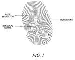
- a fingerprint is characterised by smoothly flowing ridges and valleys, characterised by their orientation, separation, shape and minutiae.
- Minutiae are ridge endings and ridge bifurcations.
- fingerprints have been the most widely accepted biometric. The formation and distinctiveness of the fingerprint has been understood since the early twentieth century (see for example Handbook of Fingerprint Recognition, D. Maltoni, et al, Springer 2003 ).
- ridge features e.g. ridge direction, ridge spacing, ridge shape etc.
- the process of fingerprint verification/identification involves two phases: (1) enrolment and; (2) matching.
- people's fingerprint image(s) are processed by computer programs and converted into a template.
- the template is then associated with meta-data of a person's identity (e.g. name, age, sex, address, etc) and stored in a database.
- acquired fingerprints are stored in a template database, where only those features of the print which are distinguishing, are extracted and represented in some form.
- a person's fingerprint images will be matched against the template, which belong to the claimed identity, whereas during identification mode (1:N matching), a person's fingerprint images will be matched against all or a subset of templates stored in the database.
- a matching score may be calculated for each comparison of the test fingerprint to a stored template.
- test fingerprint is compared against the set of stored templates and a matching score is returned. Because the test print has to be compared with each stored template, it is necessary to convert it also into the same representation as the template. Then the system can return a score based on how close is the presented (test) print with each template. If this score value is sufficiently high, determined by a user-defined threshold, then a match is declared.
- a fingerprint pattern When analysed at different levels, a fingerprint pattern exhibits different types of features:
- the third level of analysis is often used manually by fingerprint experts in forensic science when only a partial can be reliably obtained and the second level data (minutiae) are insufficient to make a conclusive match.
- Fingerprint recognition systems can be broadly classified as being minutiae based or correlation based.
- Minutiae-based approaches first find minutiae points and then map their relative placement on the finger.
- a global transformation including rotation, shift and scaling can also be identified during the establishment of correspondence between minutiae pairs.
- the correlation-based method used the global pattern of ridges and furrows and calculates a score based on the correlation result.
- a transformation matrix can be also identified when the correlation result is at a maximum.
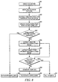
- Figure 2 is a flow chart showing the steps generally performed by a typical prior art system.
- a fingerprint image is acquired through either scanning an inked print or a live finger. Once the image is acquired into the computer memory or on a hard disk, it is often put through an enhancement process to improve the quality of the ridge pattern. This normally includes contrast enhancement, noise removal, filtering and smoothing. Some of the prior art systems also extract the foreground, i.e. ridge pattern from the background, at this step. At step three, either an image correlation method or a feature extraction process will be employed.
- Figure 3 is a flow chart showing a commonly adopted feature extraction technique proposed in " Adaptive flow orientation based feature extraction in fingerprint images", Journal of Pattern recognition, Vol. 28, no 11, pp1657-1672 Nov. 1995 and in US Patent 6,049,621 .
- the image is divided into set of blocks and the principal ridge direction of each block is then estimated.
- a foreground/background segmentation technique is then used to separate the finger part of the image from the background part of the image.
- some binarisation technique is often used to extract the ridge features (labelled as 1) from non-ridge features (labelled as 0).
- the ridge feature is often more than 1 pixel wide and may contain noisy artefacts. Those artefacts will be removed at the smoothing step and the longer structures are smoothed.
- the smoothed ridge structured is thinned to 1 pixel wide. The location and orientation of the minutiae features are then extracted from the thinned ridge structures.
- a cleanup post-processing step is employed to remove spurious minutiae features.
- the fourth step of the matching flow is normally an alignment step.
- Most of the prior art systems use the minutiae locations or cross-correlation information to identify a global affine transformation to eliminate the geometric variation including shift, and rotation between the query fingerprint and the template fingerprint.
- Some prior art systems e.g. US Patent 6,049,621 , proposed a method that is able to establish the correspondence between set points in two respective images.
- the process begins with identifying at least one point in each of the query and template images that correspond, and using this as a reference point. With the information of the location of the reference points and a curved line (thinned ridges) where the points are located, the translation and rotation parameters between the corresponding ridges are then calculated. Further, using the reference points, an index of all possible minutiae pairs between the query and template fingerprint is formed. An iterative process is then employed to identify the transformation (shift and rotation) for each minutiae pair.
- An alignment score is also calculated for each possible pair, and the pair with the score higher than a pre-defined value is declared as corresponding pairs (pair mate).
- the advantage of above approach is it can deal with not only a global transformation (shift, rotation and scaling), but also handle the local elastic deformation by calculating the transformation parameter locally. However, the success of this approach is heavily dependent on the quality of feature extraction and ridge detection.
- the matching of a password or pin number to another password or pin number involves the comparison of two absolutely defined parameters, facilitating potentially exact matches.
- the matching of fingerprints or any biometric system involves the comparison of highly complex functions and is inherently more difficult.
- Measurements and matching within biometric systems are subject to two types of errors: a False Match or a False Non Match.
- the imperfect accuracy of performance is mainly due to the large variability in different impressions of the same finger (intra-class variation), caused by displacement, rotation, partial overlap, elastic deformation, variable pressure, varying skin condition, lighting effects, noise and feature extraction errors.
- Reliably matching fingerprint images becomes a hard problem when fingerprints from the same finger may look very different, or when fingerprints from different fingers may appear quite similar.
- the inconsistency of the extracted minutiae points and ridge structures between the query fingerprint and template fingerprint is caused by several phenomena including:
- minutiae-based methods for example, it is difficult to consistently extract the minutiae points when the fingerprint is of low quality or the overlapping area between the data and the template is relatively small.
- the inconsistency of minutiae extraction will impact on both correspondence and identification of the transformation matrix itself. Correlation-based techniques are particularly prone to noise, scratches, smudges and are computationally expensive.
- the result of fingerprint matching processes is usually imperfect because of noise in acquisition, variation in the contrast, position and orientation of the print and the elastic deformation of the impression of the finger due to varying degrees of pressure that can be imparted by the subject.
- prior art fingerprint matching systems frequently comprise a number of steps to accomplish the match: (1) the acquired images are preprocessed to increase the contrast of the ridge structures; (2) features which are discriminating are extracted from the enhanced ridges, i.e. the minutiae; (3) the minutiae are compared like for like, after an alignment procedure, with the minutiae of the template.
- the template representation may simply be the locations, types (bifurcation or ending), and directions of the minutiae. All three steps have to be repeated for each match before a score can be calculated.
- fingerprint systems typically include an alignment process, which occurs prior to any matching, ensuring that images are aligned or justified in order to facilitate an accurate comparison of any two images.
- This alignment process is usually a combination of translations and rotations, which together form transformation parameters which defines the overall alignment.
- Prior art alignment methods that depend on minutiae features will inevitably fall into a combinatorial problem of two unknowns, i.e. the correspondence between minutiae points and the transformation between the minutiae set.
- the transformation parameter calculation depends on the correspondence and the establishment of correspondence rely on an accurate estimation of the transformation parameters. Any errors in either estimate will propagate and degrade the accuracy of the subsequent matching.
- the process has to be carried out in a pair wise fashion. i.e. the alignment process needs to repeated for each comparison between the query prints and all the templates.
- the alignment procedure has to be repeated multiple times until the identity of the query prints is established.
- the present invention is an image processing method, which can remove the linear and elastic geometric variation and normalize a collection of two dimensional digital images into a common framework (a canonical frame).
- the present invention also provides an image processing method for matching fingerprint images.
- One aspect of the invention involves the construction of the canonical framework. Another aspect of the invention involves the detection of sweat pore features from the fingerprint images. Another aspect of the invention involves a nonlinear alignment method to correct elastic deformation. Another involves an enrolment procedure and the other aspect of the invention involves a matching procedure.
- a method of processing fingerprint images comprising the steps of, for each image to be processed, justifying the image by translation and/or rotation and partitioning the image into a number of regions, and, for each region of the image, measuring both the prevailing ridge orientation and the average ridge separation and storing said measurement values, and, for all the processed images, projecting the said measured values for each region into a multidimensional first coordinate system and representing the images in said first coordinate system, wherein a representation distance between representations of corresponding parameters of the two images is indicative of the dissimilarity of the corresponding images.
- the method may also include the additional step of measuring the phase of the prevailing ridges storing said measured value and including said measured value in the projection of said measured values.
- the justifying step comprises identifying the biological centre and the biological axis of the fingerprint in the image, setting a common reference point and common reference axis, translating the image so that the biological centre of the fingerprint is re-located at the common reference point and rotating the image so that the biological axis of the fingerprint orientation coincides with the common reference axis. If the biological centre of the fingerprint in question is not present in the image, the off-image location of the biological centre may be estimated using a combination of extrapolation of ridges in the on-image portion of the fingerprint pattern and known patterns of fingerprints.
- a periodic wave function possibly sinusoidal, may be used as a model to simulate that part of the image in the region, wherein the said parameters are measured on said model image and/or on said real image.
- An estimation error may be computed, the estimation error being the difference between parameter measurements on the model and on the unmodelled image. If the estimation error in a particular region exceeds a predetermined threshold, then a further partitioning step may be applied to that region to create subregions of the region and the measuring step is applied within the subregions.
- Images may be represented in a first coordinate system by vectors V corresponding to the measured parameter values of each region of each image, the coordinate system forming a vector space.
- the variance or visibility of the said representation distance may be enhanced by various techniques.
- the measurement data is projected into a second coordination system, wherein the representation distance between representations of two images in the second coordinate system is greater than the representation distance between representations of two images in the first coordinate system.
- the variance or visibility may enhanced by dimension reduction, such as Principal Component Analysis (PCA), wherein at least one dimension is eliminated from the first coordinate system.
- PCA Principal Component Analysis
- a variance score may be assigned to each enhanced system according to the representation distance between the representations, the variance score being indicative of dissimilarity between the representations.
- a portion of the dimensions of the coordinate system are excluded from processing and only a non-excluded fraction K of all the dimensions are permitted to be processed, the excluded dimensions being those the elimination of which causes a variance score below that of a predetermined second threshold.
- Images may be categorised according to locations of the corresponding representations in the coordinate system. For all images of a particular category of image, a class template image may be determined, this being the mean pattern M_c for that class, c. Each of the images in the class may be partitioned into a number of regions, region size being based on distance from the core.
- the region or sub-region is not partitioned and the transformation parameter is applied without further partitioning.
- a transformation to apply to each region of an image may be determined, wherein representations of parameters of a candidate image are compared to representations of corresponding parameters in the same regions of the class template image M_c and the representation distance between the candidate image representations and the template image is determined to be the region transformation parameter.
- a score may be assigned to each comparison of representations according to the degree of similarity between the representations in the regions of the candidate image regions and those in corresponding regions of the class template image. If the score equals or exceeds a predetermined third threshold, the transformation parameter is applied to the parameters in that region of the candidate image, transforming the representations by the transformation parameter. If the score is less than a predetermined third threshold, then a further partitioning step is applied to that region to create sub-regions of the region and the measuring step is applied within the subregions and the comparison step is repeated.
- Further images may be acquired and the stored data and coordinate system may be updated accordingly.
- the locations and orientation of minutiae may be identified in each justified fingerprint image and stored.
- Data relating to sweat pores may be identified in each justified fingerprint image and stored, the data comprising at least location, shape and size of the sweat pore.
- the sweat pore and/or minutiae data may be projected into the coordinate system which is accordingly updated to include representations of these data.
- Representations may be grouped into clusters by application of a clustering technique, which may be k-means clustering or an iterative clustering technique wherein the representations are clustered according to the representation distance between them and the relative spread of current clusters.
- a clustering technique which may be k-means clustering or an iterative clustering technique wherein the representations are clustered according to the representation distance between them and the relative spread of current clusters.
- candidate images are compared against stored images in order to identify matches.
- This may further comprise the following steps: acquiring a candidate image; measuring and storing parameters of the candidate image; projecting measured values into the first coordinate system which is updated accordingly; applying the categorisation, partitioning, transformation identification, scoring and transformation steps on the candidate image; identifying the locations and orientation of minutiae in the candidate image and projected into the first coordinate system; assigning a probability score to the candidate image, the probability score being the probability that the image will qualify into a predetermined class of images; classifying said candidate image into one or more classes of images according to its probability score in those classes; comparing representations of minutiae data of the candidate image to representations of minutiae data of the template image of the same class; identifying sweat pore data in the candidate image image and stored, the data comprising at least location, shape and size of the sweat pore; comparing representations of sweat pore data of the candidate image to representations of sweat pore of the template image of the same class; a matching score assigning step
- the probability assigning step further may comprise comparing the candidate image representations to the mean of the predetermined class, and assessing the probability that the image will qualify in that class taking that mean and the spread of the representations within the class. When the assessment indicates that the candidate image does not qualify into the predetermined class, a non-match may be declared.
- an apparatus for processing fingerprint images comprising: means adapted to justify images by translation and/or rotation and partition images into a number of regions, and means for measuring in each region of each image at least one of the following parameters: the prevailing ridge orientation; the average ridge separation; the phase, and means for storing said measurement values, and means for projecting the said measured values for each region into a multidimensional first coordinate system and means for representing the images in said first coordinate system, the representation distance between representations of corresponding parameters of two images being indicative of the dissimilarity of the corresponding images.
- the apparatus may also comprise means to: identify the biological centre and the biological axis of the fingerprint in the image; set a common reference point and common reference axis; translate the image so that the biological centre of the fingerprint is re-located at the common reference point; rotate the image so that the biological axis of the fingerprint orientation coincides with the common reference axis.
- the apparatus is adapted to estimate the off-image location of the biological centre using a combination of extrapolation of ridges in the on-image portion of the fingerprint pattern and known patterns of fingerprints, if the biological centre of the fingerprint in question is not present in the image.
- the apparatus may comprise modelling means for applying a periodic wave function model, such a sinsusoidal function, to simulate that part of the image in the region, wherein the said parameters are measured on said model image and/or on the unmodelled image.
- a periodic wave function model such as a sinsusoidal function
- the apparatus may determine an estimation error, the estimation error being the difference between parameter measurements on the model and on the unmodelled image.
- the apparatus may comprise a second partitioning means wherein, if the estimation error in a particular region exceeds a predetermined first threshold, then the second partitioning means applies a second partitioning to that region to create sub-regions of the region and the measuring step is applied within the sub-regions.
- the apparatus may advantageously comprise means for representing images in said first coordinate system by vectors V which correspond to the measured parameter values of each region of each image, the coordinate system forming a vector space.
- the apparatus may also comprise means for enhancing the visibility of the said representation distance, which may be a means for projecting the measurement data into a second coordination system, wherein the representation distance between representations of two images in the second coordinate system is greater than the representation distance between representations of two images in the first coordinate system.
- the enhancement means may be a means for reducing the dimensions of the first coordination system, wherein at least one dimension is eliminated from the first coordinate system, which may be a means for applying Principal Component Analysis (PCA) obtained by Eigenvector/Eigenvalue decomposition.
- PCA Principal Component Analysis
- the apparatus may further comprise a variance score assignment means for, after each enhancement step, assigning a variance score to each enhanced system according to the representation distance between the representations, the variance score being indicative of dissimilarity between the representations.
- the apparatus may include means for excluding a portion of the dimensions of the coordinate system from processing and only a non-excluded fraction K of all the dimensions are permitted to be processed, the excluded dimensions being those the elimination of which causes a variance score below that of a predetermined second threshold.
- a further embodiment of the invention comprises means for categorising images according to locations of the corresponding representations in the coordination system and may comprise means for categorising all images of a particular category of image, the step of determining a class template image, this being the mean pattern M_c for that class, c.
- the embodiment may comprise means for partitioning each of the images in the class into a number of regions, region size being based on distance from the core.
- the apparatus may be adapted not to partition the region or sub-region and to allow transformation parameter to be applied without further partitioning if the size of the sub-region is below that of a predetermined second threshold.
- the embodiment may also comprise means for identifying a transformation, the means being adapted to: compare representations of parameters of a candidate image to representations of corresponding parameters in the same regions of the class template image M_c and determine whether the representation distance between the candidate image representations and the template image is to be the region transformation parameter.
- the apparatus may be further adapted to apply the transformation parameter to the parameters in that region of the candidate image and transform the representations by the transformation parameter, if the score equals or exceeds a predetermined third threshold. It may also be further adapted to apply further partition that region to create sub-regions of the region and apply the measuring step within the sub-regions and repeating the comparison, if the score is less than the predetermined third threshold.
- an image acquisition means for acquiring further images and updating the stored data and coordinate system accordingly.
- This may comprise a minutiae locating means for identifying the locations and orientation of minutiae in each justified fingerprint image and stored. It may also comprise a sweat pore locating means for identifying data relating sweat pores in each justified fingerprint image and stored, the data comprising at least location, shape and size of the sweat pore.
- the apparatus may include means for projecting sweat pore and/or minutiae data into the coordinate system which is accordingly updated to include representations of these data.
- clustering means for grouping representations into clusters by application of a clustering technique, which may be k-means clustering.
- the technique may an iterative clustering technique wherein the representations are clustered according to the representation distance between them and the relative spread of current clusters.
- An embodiment of the invention further comprises matching means adapted to compare candidate images against stored images in order to identify matches.
- This may be adapted to: acquire a candidate image, measure and store parameters of the candidate image, and project measured values into the first coordinate system which is updated accordingly.
- This matching means may comprise means for: applying the categorisation, partitioning, transformation identification, scoring and transformation steps on the candidate image; identifying the locations and orientation of minutiae in the candidate image and projected into the first coordinate system; assigning a probability score to the candidate image, the probability score being the probability that the image will qualify into a predetermined class of images; classifying said candidate image into one or more classes of images according to its probability score in those classes; comparing representations of minutiae data of the candidate image to representations of minutiae data of the template image of the same class; identifying sweat pore data in the candidate image image and stored, the data comprising at least location, shape and size of the sweat pore; comparing representations of sweat pore data of the candidate image to representations of sweat pore of the
- the probability assigning means may further comprise means for comparing the candidate image representations to the mean of the predetermined class, and assessing the probability that the image will qualify in that class taking that mean and the spread of the representations within the class.
- the assessment means may comprise means for declaring a non-match when the candidate image does not qualify into the predetermined class, according to the probability assessment.
- a computer program product comprisesg a readable medium containing instructions for implementing the method herein described.
- the construction of a canonical frame involves the step of: dividing the input image into a set of blocks (regions); using a parametric modelling technique to model the feature of interest within the block, specifically for fingerprint images, it is to model the ridge direction and separation within the block; identifying the intrinsic centre and orientation of the image; aligning the direction and separation pattern according to the intrinsic centre and orientation of the impression; reducing the dimensionality of the direction and separation pattern by transforming them into a new coordinate system; and projecting the reduced vector onto this co-ordinate system.
- Another aspect of the invention provides a method that extracts the sweat pore information.
- the method includes the step of: identifying the possible sweat pore locations; modelling the local intensity information around the sweat pore candidates; removing the spurious sweat pores by combining the local intensity information and its relative distance and orientation from the adjacent ridges.
- Another aspect of the invention provides a method that removes elastic deformation between two images.
- the method includes the step of: dividing the images into a set of local regions; estimating the transformation parameter between the data (query image) and the target (template image); applying the transformation parameter to each region in the query image and obtaining an alignment error; if the error is sufficiently large, which suggests that there is still an elastic deformation within the region, a subdivision of the region into a set of smaller regions is then carried out and the estimation for each smaller region is repeated; the estimation process will not stop until the error for each region is sufficiently low; applying the final transformation parameters to the corresponding region in the query image and therefore transform it into the template frame.
- a system of enrolling fingerprint images includes the steps of: acquiring a fingerprint images, modelling the ridge structures; projecting the model parameter onto the canonical frame; extracting a minutiae set from the image; extracting the sweat pore information; projecting the minutiae information onto the canonical frame; constructing and storing the template for the future use in the matching procedure; and classifying the templates based on their distance in the canonical feature space.
- a further aspect of present invention provides a method that identifies the query fingerprints from one or more stored templates.
- the method includes the step of: acquiring the query fingerprint images; modelling the ridge structures; identifying the intrinsic centre and orientation; projecting the model parameter onto the canonical feature space; calculating the probability that the query image belongs to template class; estimating the elastic deformation between the query print and each mean of the template class when the probability is high enough; applying the global and local deformation to the query fingerprints and normalising it to the mean of the corresponding class; extracting the normalized minutiae information; determining a minutiae matching score by comparing the normalized minutiae information and the information stored in each template within the class; generating an overall score based on a combination of the probability and minutiae matching information; making a matching decision comparing the overall score with a predefined value.
- the space is referred to as a canonical representation, meaning that the fingerprint images are located in a standardised space.
- the feature space representation may be compact and robust to noise in the acquired images (such as scratches).
- An important advantage of the invention is that may be applied exclusively to the model of the ridge structures (their local directions and spacing). Second level ridge features (minutiae) and third level fingerprint features (sweat pores) are not essential to convert the fingerprint into canonical form. This canonical representation is independent of the 2 nd and 3 rd level features. Thus it avoids the dilemma of having to establish the location and correspondence of such features between the test and template, while simultaneously estimating the alignment.
- the feature space may also be readily partitioned into prints belonging to the first level (pattern types such as arch, whorl etc), thus reducing the computational complexity of any 1:N pattern search.
- Fig 5 is a flowchart showing the steps of constructing the canonical framework.
- Prior art studies show that there are limited number of topological configurations of the ridge pattern, such as left loop, right loop, whorl, arch and tented arch.
- the formation of the feature space can be done in an offline mode i.e. process a collection of pre-stored fingerprint images to construct the initial feature space, or in an online mode where the construction of the feature space proceeds incrementally when enrolling and matching the prints in real time. In both cases, the process begins by using a parametric model to represent the ridge patterns.
- a hierarchical tessellation technique is used to divide image into a set of blocks (step 502)
- a parametric model is then used to model the ridge segments for each block (step 503).
- the blocks may be square, although any convenient partition of the image may be chosen.
- an estimate of characteristic parameters of the periodic ridge pattern within the block is derived by modelling the pattern to a suitable modelling functions.
- a sinusoidal model is adopted to represent the local ridge features, although other periodic smooth wave function can be used as the mathematical model.
- the orientation and frequency of the model can be estimated by many alternative techniques (step 504).
- each block is transformed to the frequency domain and the orientation and frequency of the signal can be estimated by locating the peak of the magnitude spectrum.
- the ridge pattern within the block may then synthesized using the sinusoidal model with the estimated parameter of frequency and orientation.
- the phase of the ridge segments is also estimated, by calculating an inner product between the data and the synthesized model.
- an estimation error can also be calculated be comparing the synthesized model and the real data.
- the error may vary from region to region, as a result of non-uniform effects, such as displacement, rotation, partial overlap, elastic deformation, variable pressure, varying skin condition, lighting effects, noise and feature extraction errors, as indicated earlier.
- the error may be estimated for each region: in regions where the error is higher than a predetermined level, this may be considered as an indicator that the data in the region is too complex to be estimated by the current model. Where this occurs the region can be subdivided into a set of smaller regions. Step 504 may be repeated until all the regions of the image are modelled and all the modelling error is lower than a pre-determined level in each region.
- Steps 505 and 506 are centring and alignment steps: these aim to re-centre the biological centre of the fingerprint with the image's geometric centre and to re-align the fingerprint orientation with a general axis.
- Figure 5 illustrates these as occurring after Step 504, but these may also take place before Step 504.
- a fingerprint core is an area located within the innermost ridges. Normally it is located in the middle of the fingerprint, however, depending on the scanned area, it might not be positioned in the middle of the image, or indeed might not even present in the image. When the core is present in the image, it can be detected by many alternative techniques. In a preferred embodiment of our invention, a set of circular symmetric functions is used to locate the location and orientation of the core (step 505).
- the output of the convolution is taken as the sum of the absolute values of the dot products of the (S, D) image and the kernel (I, J).
- the image position of the maximum value is taken as the nominal intrinsic centre.
- the principal orientation of the print is estimated by the modal value of a histogram of the directions (D) in circular region around the centre of radius 96 pixels.
- the centre (x, y) of the core and the principal direction P are stored for the print.
- the core When the core is not present, its position can only be estimated by convolution (step 505) with respect to a representative template prototype of each partition (step 509).
- This prototype pattern is the mean of a population of learnt templates.
- the output is therefore one or more core locations (x, y) and principal directions P each of which are subsequently characterized (step 510).
- the collection of estimated ridge directions and separations are shifted and rotated with respect a common origin (core) and principal orientation (step 506).
- each region may be represented by a three dimensional vector corresponding to the derived estimates of ridge orientation, separation and phase from the mathematical modelling of the ridge pattern in Steps 503 and 504.
- the total dimensions of the pattern vector for all regions of each complete fingerprint may be of the order of hundreds or thousands, each finger print being represented by a collection of regional vectors.
- the matching process (not part of Figure 5 ), whether verification or identification, is essentially a comparison between two fingerprints (see earlier).
- the comparison between prints requires a distance measure between the collection of vectors for each print. This involves calculations in a vector space of very high dimensions, which requires considerable computing capacity, which may be inefficient and expensive.
- An object of the invention is that it advantageously lowers the computation requirement to within normal computing capacity.
- the dimensionality of the feature space may be reduced by various techniques (step 507), the collection of vectors is projected into a new coordinate system such that the greatest variance by any projection of the data comes to lie on the first axis (call the first principal component), the second greatest variance on the second axis, and so on.
- M E[V].
- C E[(V-M)(V-M) ⁇ T]
- ⁇ T being the transpose of the vector or matrix
- E[] the expectation operator.
- a new set of principal feature directions, V' is obtained by PCA.
- the set of eigenvalues of the eigenvectors produced by the PCA, E then form the basis set of the canonical feature space.
- the feature vectors V' may be made compact by only taking a subset which encapsulate some percentage, K, of the variation, e.g. K can be reasonably set to be 95% of the total variation.
- V' (E1, E2, E3, E4 ... EK)(a1, a2, a3, a4, ... aK) ⁇ T, where a1..aK are a set of scalars, and E1..EK are the unit length eigenvectors of the covariance matrix C ( ⁇ T is the transpose as before).
- K is selected in step 507 such that the total variation is less than some percentage e.g. 95%.
- the system may use the successful matches to learn and update the parameters of the stored template (its mean and covariance in the canonical feature space).
- the parameters of the stored template its mean and covariance in the canonical feature space.
- LDA Linear Discriminant Analysis
- kernel LDA kernel LDA
- the aligned vectors which represent each fingerprint image, can thus be projected onto a vector space V and thereafter, using the above dimension reduction techniques or other alternative techniques, onto a common feature space V', which is invariant to the presentation of the print (step 508).
- each image After processing all the images either in an offline mode or online mode, each image will be presented as a point in the reduced feature space. Depending on the dimension reduced, different variations between points may become apparent, thereby enhancing or suppressing similarities between points.
- An advantage of the invention is that by projecting values of fingerprint parameters, measured region by region, into a fingerprint space containing, for example vectors, representing those parameters, the data can be processed flexibly Enhancing the data by the methods indicated above, such as dimensionality reduction, allows the user to bring out or diminish similarities between fingerprints in a way vastly more convenient than any prior art techniques.
- clustering techniques can then be applied to partition the space of prints (step 509).
- One method is k-means clustering, which is a two step procedure: each template is first associated or labelled to the closest prototype of an initial set of M cluster prototypes; the locations of these prototypes is then updated by moving to the current labelling.
- Another iterative method is to use both the distance between templates and the relative spread of the current set of clusters.
- the clusters are discovered by hierarchical grouping into larger and larger clusters. In some methods, the number of clusters M may be input to the algorithm, or they me be discovered, as is the case of certain hierarchical agglomeration clustering methods.
- the invention offers the advantage of managing a large and highly complex data set.
- a canonical feature space ie a representative multidimensional coordinate system
- the data can be manipulated more conveniently and dissimilarities between images brought out more easily.
- the effects of noise, scratches may be eliminated relatively easily in the canonical feature space.
- a further advantage of the invention as proposed is the non-reliance on minutiae and sweat pores, which, in many prior art systems, are essential for achieving any degree of accuracy in measuring or matching fingerprints - the invention disclosed may indeed be combined with data related to sweat pores and minutiae, but in its simplest form is independent of these.
- Fig 6 is a flowchart showing the steps of detecting the sweat pore information.
- ridge patterns can be explicitly represented by some periodical mathematical model.
- the ridge information can thus be removed from the original image by subtracting the reconstruction of the ridge pattern from the original data (step 601).
- the residual information will contain sweat pores and other background feature noise.
- the generic profile of sweat pores is believed to be round (blob) shaped type of features and generally have higher intensity values than the background, however, their size and shape can vary and sometimes the boundary can be highly irregular. A consistent and robust identification of sweat pore features is therefore challenging.
- a 2D Hermite polynomial is used to model the sweat pore features.
- the candidate or putative region is first identified by locating the pixels with high intensity values, a window is placed around those pixels and are then labelled as a candidate or putative region (step 602).
- a parametric model is use to represent the putative pore in each region. (step 603).
- the original data within the region is first modelled by a 2D Gaussian intensity profile where the parameters, i.e., mean and co-variance of the intensity model, can be estimated using an iterative maximum likelihood method.
- An alternative embodiment is to use a Minimum Mean Square Error technique to estimate the parameters.
- the Gaussian profile can very accurately model the round shape features, however it is insufficient for features with irregular shapes.
- the use of a Hermite polynomial is to increase the flexibility of the model and therefore improve the modelling accuracy. In a preferred embodiment, only the first few Hermite coefficients are used to represent sweat pore features.
- a filtering step (step 604) is proposed on an embodiment of the present invention.
- a filtering of the putative pores based on their shape can be applied.
- the covariance of the Hermite polynomial parameters estimated in the pore modelling step 603 are analysed using Principal Component Analysis.
- the principal modes that encapsulate some proportion of the total variation, e.g. 90% or 95%, are used to filter out pores that have projections of their Hermite polynomial coefficients that lie outside the chosen region of variation in the feature (shape) space calculated by the PCA.
- a user-defined threshold can be used to control the strictness of the shape filtering which results.
- This particular embodiment is a linear method of filtering unlikely shape differences, but the invention does not exclude the use of non-linear shape modelling techniques such as kernel PCA.
- the location of the pores are considered in relation to the ridge patterns of the impression (step 503). Firstly, only putative pores that overlap with the ridges are considered. For the preferred embodiment, those putative pores whose nominal area significantly overlaps a ridge are passed on to the next filter; those that do not are removed.
- the second location filter considers those pores that lie more or less on the centre line of the ridge (along the direction of the ridge). A small variability in position perpendicular to the ridge direction is allowed in proportion to the nominal ridge spacing is allowed. This is a predefined parameter.
- the next location filter considers the relative frequency of the pores along the entire ridge and a harmonic expansion of the pore locations along the ridge (along the arc length of the ridge centre line) is used to determine the fundamental periodic frequency. Pore locations at higher harmonic frequencies are deleted.
- the fundamental frequency can be learned using similar, high quality impressions, or learnt from the current impression.
- a Fourier analysis of the 1D signal of putative pore positions along the arc length can be used to perform the harmonic analysis.
- these pore shape and pore location filters may be applied in this order, although other combinations of ordering can be envisaged.
- both shape and location filters can be used, but whether both are applied will depend on quality of the acquired images and the proportion of the artefactual to true pores detected at steps 601 and 603.
- Image alignment removes the geometric variation among prints that is caused by scanning the fingerprint images acquired at different angles and displacements on the scanning device.
- prior art systems align the fingerprint images based on the minutiae information, which inevitably fall into a combinatorial problem of two unknowns, i.e. the transformation between the minutiae set and the correspondence between the minutiae points.
- Image alignment according to the invention may be based on the previously mentioned ridge parameters and may therefore be independent of minutiae distributions.
- the alignment method of the invention can advantageously also remove the elastic deformation caused by scanning distortion, uneven downward pressure when the fingerprint is placed to the scanning surface, twisting and various other factors. Under prior art minutiae alignment techniques, such deformations and distortions are difficult to accommodate in a systematic way and can lead to inaccuracies.
- Fig 7 is a flowchart showing an embodiment according to the image alignment method of the current invention.
- the two input of fig 7 are representations of a query image and the mean of the class the query image belongs to.
- the two inputs of Fig 7 is a representation of query image or candidate image and a representation of a image template that has previously been enrolled. This latter implementation is a preferred embodiment for 1:1 matching (verification).
- the representation of the image is the multidimensional feature set ⁇ separation, direction and phase ⁇ generated by using (step 501-506).
- the candidate and stored template may be tessellated, thereby creating a number of regions for each image.
- the feature set for each input is grouped into a set based on its relative position to the core location. Each group will represent a region of the image. The size of the region may thus be dependent on the distance from the core.
- step 702 is to estimate the transformation parameters ⁇ scale, rotation, shift ⁇ to be applied to each group (region) to offset the deformation and distortion processes indicated above.
- a recursive filtering technique is used to estimate the transformation parameters, this being the transformation to be applied to each region.
- the candidate image is essentially compared to a template representing a given class of images, with which the candidate image is associated.
- the representation points for each region of the candidate image are compared to the corresponding representations in the same regions of the class template, the difference between them being indicative of the transformation required to eliminate the distortion in that particular region.
- the estimation of the transformation process is an iterative process, with a prediction and update step at each iteration.
- the prediction step is based on the estimates at previous iterations and the updating is based on the error in the new measurement, according to the prediction.
- the above implementation may be considered to have converged when the difference between the estimate at the previous and current iterations is sufficiently small. According to the above implementation, optimal transformation parameters that best align two corresponding regions in query and template images are thus obtained.
- the estimated transformation parameters are then applied to the corresponding regions of a query image to align the region to the corresponding one in the template (step 703).
- An alignment score for each region is then calculated at the next step (step 704) by comparing the similarity between the corresponding region in a template image and aligned query image. If the alignment score is not high enough, it suggests that there is still some elastic deformation within the region and it should thus be divided into a number of smaller regions and steps (702-704) are repeated until the alignment score for each region is high enough or the number of data too few to carry out the recursive calculation at step 702.
- the transformation parameters for both global and elastic deformations are obtained by interpolating the transformation parameters estimated for each region (step 707).
- the interpolated transformation is then applied to the query image and aligned it to either the mean of the class or the individual template depending on the implementation.
- the advantage of the alignment system according to the invention is that distortions in the fingerprint image, due to excess or uneven pressure during extraction, finger roll etc (as described earlier), may be compensated for more easily than in prior art systems.
- the improvement in alignment enhances the normalisation effect throughout the data set and minimises the chances of, for example, a mismatch of two images of the same finger.
- Fingerprint recognition systems have two principal modes of operation: enrolment and matching.
- enrolment acquired fingerprints are stored in a template database, where only those features of the print that are distinguishing are extracted and represented in some form.
- Fig 8 is a flowchart showing a preferred embodiment according to the enrolment mode of the current invention.
- the enrolment process starts from acquiring a fingerprint image from a scanning device (step 801). At the next step (step 802), it is then divided into a set of regions (step 502) and the ridge pattern of each region is modelled, according to previously described methods (at step 503) and the ridge orientation and separation of each region is estimated. The location and orientation of the core is also located the same way as described at (step 505). The parameter set ⁇ separation, direction ⁇ is then projected to the canonical feature space as suggested at Fig 5 .
- step (809) is carried out and a duplicate enrolment is declared, i.e. the fingerprint has already been enrolled in the database. Otherwise, the feature space is updated with the new candidate and the classification and clustering steps (509, 510) will also need to be recalculated with the information from the new image.
- the minutiae information i.e. the location, orientation and ridge count may be extracted from the enrolment image. This information may be also aligned to the canonical feature space.
- Step 807 is an optional step and it is to extract the pore information from the input image.
- the information includes the location, shape and distribution of sweat pore features. A detailed embodiment is given above and shown in Fig 6 . If the number of detected minutiae and the number of detected sweat pores are lower than a predefined value, which is configurable by the end user, step 811 is performed again and an enrolment failure is declared. Otherwise, the location of the image in the canonical feature space, the information of which class and sub-class it belongs to, the ridge parameters, the location and orientation of its core, the minutiae and sweat pore information are encoded and stored as a template image.
- the template can be generated in a multi-layer fashion so that any part of the information can be used by any foreign method or computer program that can only utilize that part of the information, such as location, type and/or the orientation of the minutiae.
- the process of fingerprint matching involves comparing a query print with a set of one or more template prints.
- a verification mode i.e. a one to one match is sought and; an identification mode, i.e. a one to many match is sought.
- the following disclosure is based on the identification mode, however, with only a slight modification of the flow, the implementation can be easily adapted to the verification mode.
- Fig 9 is a flowchart showing a preferred embodiment of current invention.
- step 901 After acquiring the image (query) from the scanning device, it is divided into a set of local regions and each region is modelled and ridge information is identified (step 901) and further mapped into the canonical feature space (step 902). Both steps use the same methodology as the one explained in the enrolment process.
- step 903 based on its position in the feature space, the probability that the query image belongs to certain class and sub-class is calculated.
- the probability of membership of a given query print, Q, belonging to a particular class, c, can be expressed as the posterior probability P(c
- V(Q) is the projection of Q into the canonical feature space V (step 508).
- step 509 will suggest other ways to calculate the membership or classification probability: P(c
- the choice of probability model, whether parametric or non-parametric, may be connected with the partitioning process used at step 510. Such variations are under the contemplation of this invention.
- step 914 is performed and a non-match declared. Otherwise the system will proceed to step 905.
- the ridge parameter set of the query image is compared with the mean parameter set for each class. And both linear and non-linear deformation between the two parameters is removed using a method described at image alignment step. The estimated transformation parameters are then applied to the query image.
- the minutiae information may be extracted from the aligned query image and compared with the corresponding information in each stored template within the partition class. If the number of minutiae is two low, then algorithm may proceed to step 908, which extracts the sweat pore information (explained in detail at the description of Fig 6 ). If there are sufficient minutiae present at step 906, the query and stored templates are compared and a matching score is generated purely from minutiae and the probability, step (909). Otherwise the sweat pore information is used to compare the query and the corresponding information in each template within the class.
- a combined matching score (909) may be then generated with the combination of the probability measurement calculated at step 903, minutiae and/or sweat pore information.
- the two scores one that expresses the 'belonging to the nearest patter class c' and; the other expressing the similarity of the minutiae/sweat pore patterns between the query print Q and each template R_c in class c, are combined by taking the product of the two scores expressed as probabilities.
- P(Q matches R_c) P(c
- the first probability is the same as estimated in step 903, and there are many known ways in which a similarity score based on minutiae and/or pore locations can be readily expressed as a probability. If any of the matching score within the class are higher than a predefined threshold, the system will declare a match between the query image and corresponding template. Otherwise, step 905 is returned to and the templates within another qualifying class are processed. In the preferred embodiment, the order of processing subsequent qualifying classes (and the templates contained within) is determined by taking the largest of the 'belonging' scores calculated at step 903 first. When all the templates in all the qualifying classes have been compared against the query image, and none of the matching scores are higher than the predefined threshold value, the system will declare a non-match.
Landscapes
- Engineering & Computer Science (AREA)
- Physics & Mathematics (AREA)
- General Physics & Mathematics (AREA)
- Multimedia (AREA)
- Theoretical Computer Science (AREA)
- Human Computer Interaction (AREA)
- Computer Vision & Pattern Recognition (AREA)
- Collating Specific Patterns (AREA)
- Image Analysis (AREA)
- Measurement Of The Respiration, Hearing Ability, Form, And Blood Characteristics Of Living Organisms (AREA)
Claims (18)
- Verfahren zur Verarbeitung von Fingerabdruckbildern, die folgenden Schritte umfassend:i) Ausrichten jedes Bildes durch Parallelverschiebung und/oder Drehung;ii) Unterteilen (502) jedes Bildes in eine Anzahl von Regionen;iii) für jede Region jedes Bildes: Messen (504) von Parametern der Region, wobei die Parameter die vorherrschende Richtung von Papillarleisten und den durchschnittlichen Abstand der Papillarleisten beinhalten; und Speichern der Parameter;iv) Projizieren der Parameter für jede Regionwobei der Ausrichtungsschritt umfasst:
in ein mehrdimensionales erstes Koordinatensystem und Darstellen der Bilder in dem ersten Koordinatensystem, wobei ein Darstellungsabstand zwischen Darstellungen einander entsprechender Parameter zweier Bilder die Verschiedenheit der entsprechenden Bilder anzeigt;a) Identifizieren (505) des biologischen Mittelpunkts und der biologischen Achse des Fingerabdrucks auf dem Bild;b) Einstellen eines gemeinsamen Referenzpunkts und einer gemeinsamen Referenzachse;c) Parallelverschieben (506) des Bildes so, dass der biologische Mittelpunkt des Fingerabdrucks auf dem gemeinsamen Referenzpunkt zu liegen kommt;d) Drehen (506) des Bildes so, dass die biologische Ausrichtungsachse desFingerabdrucks mit der gemeinsamen Referenzachse übereinstimmt; und wobei, wenn der biologische Mittelpunkt des betreffenden Fingerabdrucks in dem Bild fehlt, eine außerhalb des Bildes liegende Position des biologischen Mittelpunkts anhand einer Kombination aus Extrapolation von Papillarlinien in einem innerhalb des Bildes liegenden Abschnitt des Fingerabdrucks und bekannten Fingerabdruckmustern bestimmt wird. - Verfahren nach Anspruch 1, wobei die Parameter eine Phase der vorherrschenden Papillarlinien beinhalten.
- Verfahren nach einem der vorangehenden Ansprüche, die Anwendung eines periodischen Wellenfunktionsmodells beinhaltend zum Simulieren dieses Teils des Bildes in der Region, um ein Modellbild zu erzeugen, wobei die Parameter am Modellbild und/oder am Bild gemessen werden.
- Verfahren nach Anspruch 3, einen Bestimmungsfehler-Messungsschritt umfassend, in dem ein Bestimmungsfehler festgestellt wird, wobei der Bestimmungsfehler der Unterschied zwischen Parametermessungen am Modellbild und am Bild ist, und wobei, wenn der Bestimmungsfehler in einer bestimmten Region einen vorgegebenen ersten Schwellenwert überschreitet, ein zweiter Teilungsschritt (706) auf diese Region angewendet wird, um Teilregionen der Region zu erzeugen, und der Vermessungsschritt innerhalb der Teilregionen angewendet wird.
- Verfahren nach einem der vorangehenden Ansprüche, eine Projektion (507) der Parameter in ein zweites Koordinatensystem umfassend, wobei der Darstellungsabstand zwischen Darstellungen zweier Bilder im zweiten Koordinatensystem größer ist als der Darstellungsabstand zwischen Darstellungen zweier Bilder im ersten Koordinatensystem.
- Verfahren nach Anspruch 5, einen Dimensionsverringerungsschritt (507) umfassend, wobei mindestens eine Dimension des ersten Koordinatensystems aus dem zweiten Koordinatensystem eliminiert wird.
- Verfahren nach einem der vorangehenden Ansprüche, einen Abweichungsbepunktungsschritt umfassend, in dem jedes verarbeitete Bild gemäß dem Darstellungsabstand zwischen den Darstellungen bepunktet wird, wobei die Abweichungsbepunktung eine Verschiedenheit der Darstellungen anzeigt.
- Verfahren nach Anspruch 7, ferner einen Ausschließungsschritt umfassend, in dem ein Abschnitt der Dimensionen des Koordinatensystems von der Verarbeitung ausgeschlossen wird und nur eine nicht ausgeschlossene Teilmenge K sämtlicher Dimensionen verarbeitet werden darf, wobei die ausgeschlossenen Dimensionen diejenigen sind, deren Eliminierung eine Abweichungsbepunktung unterhalb derjenigen eines vorgegebenen Schwellenwerts ergibt.
- Verfahren nach einem der vorangehenden Ansprüche, ferner eine Einteilung von Bildern in Kategorien beinhaltend, die Positionen der entsprechenden Darstellungen im Koordinatensystem entsprechen.
- Verfahren nach Anspruch 9, ferner für alle Bilder einer bestimmten Bildkategorie den Schritt der Festlegung eines Klassenschablonenbildes umfassend, wobei es sich dabei um das Mittelwertmuster M dieser Kategorie handelt.
- Verfahren nach Anspruch 10, ferner die Unterteilung jedes Bildes in der Kategorie in eine Anzahl von Regionen umfassend, wobei die Regionsgröße auf einem Abstand von einem biologischen Mittelpunkt des Fingerabdrucks in dem Bild beruht.
- Verfahren nach Anspruch 11, ferner einen Transformationsidentifizierungsschritt umfassend, wobei Darstellungen von Parametern eines zu prüfenden Bildes mit Darstellungen von entsprechenden Parametern in den gleichen Regionen des Klassenschablonenbildes M verglichen werden; und
ein Darstellungsabstand zwischen den zu prüfenden Bilddarstellungen und dem Vorschaubild als Regionstransformationsparameter festgestellt wird. - Verfahren nach Anspruch 12, ferner einen Bepunktungsschritt umfassend, in dem jeder Darstellungsvergleich entsprechend dem Grad einer Ähnlichkeit zwischen den Darstellungen in den Regionen der zu prüfenden Bildregionen und denen in entsprechenden Regionen des Klassenschablonenbildes bepunktet wird.
- Verfahren nach Anspruch 13, wobei, wenn eine Punktezahl einen vorgegebenen Schwellenwert erreicht oder überschreitet, der Transformationsparameter an die Parameter in dieser Region des zu prüfenden Bildes angelegt wird, wodurch die Darstellungen mit dem Transformationsparameter transformiert werden.
- Verfahren nach einem der Ansprüche 13 oder 14, wobei, wenn die Punktezahl kleiner ist als ein vorgegebener Schwellenwert, ein weiterer Unterteilungsschritt an diese Region angewendet wird, um Teilregionen dieser Region zu bilden, und der Messungsschritt innerhalb der Teilregionen angewendet wird und der Vergleichsschritt wiederholt wird.
- Verfahren nach einem der vorangehenden Ansprüche, einen Bildabgleichschritt umfassend, wobei zu prüfende Bilder mit gespeicherten Bildern verglichen werden, um Übereinstimmungen zu identifizieren.
- Vorrichtung zur Verarbeitung von Fingerabdruckbildern, aufweisend:i) eine Einrichtung, die dafür ausgelegt ist, jedes Bild durch eine Parallelverschiebung und/oder Drehung auszurichten;ii) eine Einrichtung, die dafür ausgelegt ist, jedes Bild in eine Anzahl von Regionen zu unterteilen (502);iii) eine Einrichtung, die für jede Region jedes Bildes Parameter der Region misst (504), wobei die Parameter die Richtung von vorherrschenden Papillarleisten und den durchschnittlichen Abstand der Papillarleisten beinhalten; und die Parameter speichert;iv) eine Einrichtung zum Projizieren der Parameter für jede Region in ein mehrdimensionales erstes Koordinatensystem und eine Einrichtung zum Darstellen der Bilder in dem ersten Koordinatensystem, wobei ein Darstellungsabstand zwischen Darstellungen einander entsprechender Parameter zweier Bilder die Verschiedenheit der entsprechenden Bilder anzeigt;wobei die Einrichtung, die dafür ausgelegt ist, jedes Bild auszurichten, so gestaltet ist, dass sie:a) den biologischen Mittelpunkt und die biologischen Achse des Fingerabdrucks auf dem Bild identifiziert (505);b) einen gemeinsamen Referenzpunkt und eine gemeinsame Referenzachse einstellt;c) eine Parallelverschiebung des Bildes durchführt (506), so dass der biologische Mittelpunkt des Fingerabdrucks auf dem gemeinsamen Referenzpunkt zu liegen kommt;d) das Bild so dreht (506), dass die biologische Achse der Fingerabdruckrichtung mit der gemeinsamen Referenzachse übereinstimmt;und wobei die Einrichtung, die dafür ausgelegt ist, jedes Bild auszurichten, so ausgelegt ist, dass, wenn der biologische Mittelpunkt des betreffenden Fingerabdrucks in dem Bild fehlt, eine außerhalb des Bildes liegende Position des biologischen Mittelpunkts anhand einer Kombination aus Extrapolation der Papillarlinien in einem im Bild liegenden Abschnitt des Fingerabdrucks und bekannten Fingerabdruckmustern bestimmt wird.
- Computergeneriertes Programmprodukt, ein lesbares Medium aufweisend, das Anweisungen zum Implementieren eines Verfahrens zur Verarbeitung von Fingerabdruckbildern gemäß einem der Ansprüche 1 bis 16 auf einem geeigneten Computer enthält.
Applications Claiming Priority (2)
| Application Number | Priority Date | Filing Date | Title |
|---|---|---|---|
| GB0712084A GB2450479A (en) | 2007-06-22 | 2007-06-22 | Fingerprint recognition including preprocessing an image by justification and segmentation before plotting ridge characteristics in feature space |
| PCT/GB2008/050468 WO2009001121A1 (en) | 2007-06-22 | 2008-06-19 | Fingerprint matching method and apparatus |
Publications (2)
| Publication Number | Publication Date |
|---|---|
| EP2174261A1 EP2174261A1 (de) | 2010-04-14 |
| EP2174261B1 true EP2174261B1 (de) | 2012-03-07 |
Family
ID=38352697
Family Applications (1)
| Application Number | Title | Priority Date | Filing Date |
|---|---|---|---|
| EP08762576A Ceased EP2174261B1 (de) | 2007-06-22 | 2008-06-19 | Verfahren und vorrichtung zum fingerabdruckvergleich |
Country Status (6)
| Country | Link |
|---|---|
| US (1) | US8588484B2 (de) |
| EP (1) | EP2174261B1 (de) |
| AT (1) | ATE548707T1 (de) |
| CA (1) | CA2712233A1 (de) |
| GB (1) | GB2450479A (de) |
| WO (1) | WO2009001121A1 (de) |
Cited By (2)
| Publication number | Priority date | Publication date | Assignee | Title |
|---|---|---|---|---|
| WO2016025540A1 (en) * | 2014-08-11 | 2016-02-18 | Synaptics Incorporated | Multi-view fingerprint matching |
| TWI709918B (zh) * | 2018-12-03 | 2020-11-11 | 大陸商北京集創北方科技股份有限公司 | 提高手指識別率的處理方法及其指紋識別裝置 |
Families Citing this family (38)
| Publication number | Priority date | Publication date | Assignee | Title |
|---|---|---|---|---|
| US8077933B1 (en) * | 2006-09-06 | 2011-12-13 | Fiske Software, Llc | Matching prints with feature collections |
| US8411913B2 (en) * | 2008-06-17 | 2013-04-02 | The Hong Kong Polytechnic University | Partial fingerprint recognition |
| CN102124489B (zh) * | 2008-08-17 | 2014-08-06 | 杜比实验室特许公司 | 图像的签名推导 |
| US8923576B2 (en) * | 2009-09-22 | 2014-12-30 | Thales | Method for detecting a fake finger for fingerprint acquisition software |
| JP5454672B2 (ja) * | 2010-03-01 | 2014-03-26 | 富士通株式会社 | 生体情報処理装置及び方法 |
| US8391590B2 (en) * | 2010-03-04 | 2013-03-05 | Flashscan3D, Llc | System and method for three-dimensional biometric data feature detection and recognition |
| US8429137B2 (en) * | 2010-09-02 | 2013-04-23 | Federal Express Corporation | Enterprise data duplication identification |
| US8532391B2 (en) * | 2010-09-30 | 2013-09-10 | Intuit Inc. | Recognizing a feature of an image independently of the orientation or scale of the image |
| CN102368241A (zh) * | 2011-09-07 | 2012-03-07 | 常州蓝城信息科技有限公司 | 多级指纹数据库检索方法 |
| CN103294987A (zh) * | 2012-03-05 | 2013-09-11 | 天津华威智信科技发展有限公司 | 指纹匹配方法与实现方式 |
| KR102182319B1 (ko) | 2013-06-05 | 2020-11-25 | 삼성전자주식회사 | 전자 기기 및 전자 기기에서 배터리 정보 제공 방법 |
| US10552511B2 (en) * | 2013-06-24 | 2020-02-04 | Infosys Limited | Systems and methods for data-driven anomaly detection |
| KR102123092B1 (ko) * | 2013-11-21 | 2020-06-15 | 삼성전자주식회사 | 지문 인식 방법 및 그 전자 장치 |
| FR3017230B1 (fr) * | 2014-02-04 | 2016-03-11 | Morpho | Procede de validation de l'utilisation d'un vrai doigt comme support d'une empreinte digitale |
| CN103902970B (zh) * | 2014-03-03 | 2017-09-22 | 清华大学 | 自动指纹姿态估计方法及系统 |
| US10025831B2 (en) * | 2014-05-15 | 2018-07-17 | Bio-Key International, Inc. | Adaptive short lists and acceleration of biometric database search |
| US10007840B2 (en) * | 2014-12-31 | 2018-06-26 | Alcohol Countermeasure Systems (International) Inc. | System for video based face recognition using an adaptive dictionary |
| US10521642B2 (en) * | 2015-04-23 | 2019-12-31 | Samsung Electronics Co., Ltd. | Fingerprint verification method and apparatus |
| DE102016005636A1 (de) * | 2015-06-08 | 2016-12-22 | Cross Match Technologies, Inc. | Transformierte Repräsentation für Fingerabdruckdaten mit hoher Erkennungsgenauigkeit |
| US10733415B1 (en) | 2015-06-08 | 2020-08-04 | Cross Match Technologies, Inc. | Transformed representation for fingerprint data with high recognition accuracy |
| US10339178B2 (en) * | 2015-06-30 | 2019-07-02 | Samsung Electronics Co., Ltd. | Fingerprint recognition method and apparatus |
| US9471765B1 (en) * | 2015-07-01 | 2016-10-18 | Fingerprint Cards Ab | Fingerprint authentication with template updating |
| US10002285B2 (en) | 2015-09-25 | 2018-06-19 | Qualcomm Incorporated | Fast, high-accuracy, large-scale fingerprint verification system |
| US9846982B2 (en) * | 2015-10-30 | 2017-12-19 | Ncr Corporation | Document geometric deformation watermarking and tracking |
| US9846800B2 (en) * | 2015-11-16 | 2017-12-19 | MorphoTrak, LLC | Fingerprint matching using virtual minutiae |
| US9626549B1 (en) * | 2015-11-16 | 2017-04-18 | MorphoTrak, LLC | Derived virtual quality parameters for fingerprint matching |
| CN105426877B (zh) * | 2015-12-22 | 2019-09-10 | 金虎林 | 利用汗腺位置信息的信息识别方法及系统 |
| CN107091704B (zh) * | 2016-02-17 | 2020-10-09 | 北京小米移动软件有限公司 | 压力检测方法和装置 |
| US9946917B2 (en) | 2016-03-31 | 2018-04-17 | Synaptics Incorporated | Efficient determination of biometric attribute for fast rejection of enrolled templates and other applications |
| CN109886212A (zh) * | 2019-02-25 | 2019-06-14 | 清华大学 | 从滚动指纹合成现场指纹的方法和装置 |
| CN111695386B (zh) * | 2019-03-15 | 2024-04-26 | 虹软科技股份有限公司 | 一种指纹图像增强、指纹识别和应用程序启动方法 |
| JP7251619B2 (ja) * | 2019-05-28 | 2023-04-04 | 日本電気株式会社 | 情報処理装置、情報処理方法及びプログラム |
| GB2585704A (en) * | 2019-07-12 | 2021-01-20 | Algorid Ltd | Apparatus and methods for parameterising images of friction skin ridges |
| CN114255355A (zh) * | 2020-09-24 | 2022-03-29 | 北京四维图新科技股份有限公司 | 目标对象匹配方法及装置 |
| CN114168081B (zh) * | 2021-12-09 | 2024-09-13 | 中国电信股份有限公司 | 高维特征存储方法及装置、存储介质、电子设备 |
| CN114926865A (zh) | 2022-05-07 | 2022-08-19 | 三星(中国)半导体有限公司 | 指纹识别方法、装置、电子设备及存储介质 |
| FR3139228B1 (fr) * | 2022-08-26 | 2024-10-04 | Idemia Identity & Security France | Procédé de vérification de l’authenticité d’une empreinte digitale |
| JP2024084569A (ja) * | 2022-12-13 | 2024-06-25 | 東京エレクトロン株式会社 | 接続組立体、および検査装置 |
Family Cites Families (4)
| Publication number | Priority date | Publication date | Assignee | Title |
|---|---|---|---|---|
| JP2735098B2 (ja) * | 1995-10-16 | 1998-04-02 | 日本電気株式会社 | 指紋特異点検出方法及び指紋特異点検出装置 |
| US5909501A (en) * | 1996-09-09 | 1999-06-01 | Arete Associates | Systems and methods with identity verification by comparison and interpretation of skin patterns such as fingerprints |
| US6487306B1 (en) * | 1997-08-22 | 2002-11-26 | International Business Machines Corporation | System and method for deriving a string-based representation of a fingerprint image |
| JP4032241B2 (ja) | 2003-02-28 | 2008-01-16 | 日本電気株式会社 | 指紋照合装置及びその方法 |
-
2007
- 2007-06-22 GB GB0712084A patent/GB2450479A/en not_active Withdrawn
-
2008
- 2008-06-19 AT AT08762576T patent/ATE548707T1/de active
- 2008-06-19 US US12/666,186 patent/US8588484B2/en active Active
- 2008-06-19 CA CA2712233A patent/CA2712233A1/en not_active Abandoned
- 2008-06-19 EP EP08762576A patent/EP2174261B1/de not_active Ceased
- 2008-06-19 WO PCT/GB2008/050468 patent/WO2009001121A1/en not_active Ceased
Cited By (3)
| Publication number | Priority date | Publication date | Assignee | Title |
|---|---|---|---|---|
| WO2016025540A1 (en) * | 2014-08-11 | 2016-02-18 | Synaptics Incorporated | Multi-view fingerprint matching |
| US9508022B2 (en) | 2014-08-11 | 2016-11-29 | Synaptics Incorporated | Multi-view fingerprint matching |
| TWI709918B (zh) * | 2018-12-03 | 2020-11-11 | 大陸商北京集創北方科技股份有限公司 | 提高手指識別率的處理方法及其指紋識別裝置 |
Also Published As
| Publication number | Publication date |
|---|---|
| WO2009001121A1 (en) | 2008-12-31 |
| GB2450479A (en) | 2008-12-31 |
| ATE548707T1 (de) | 2012-03-15 |
| US8588484B2 (en) | 2013-11-19 |
| CA2712233A1 (en) | 2008-12-31 |
| EP2174261A1 (de) | 2010-04-14 |
| GB0712084D0 (en) | 2007-08-01 |
| US20100266168A1 (en) | 2010-10-21 |
Similar Documents
| Publication | Publication Date | Title |
|---|---|---|
| EP2174261B1 (de) | Verfahren und vorrichtung zum fingerabdruckvergleich | |
| Chen et al. | Iris recognition based on bidimensional empirical mode decomposition and fractal dimension | |
| Zaeri | Minutiae-based fingerprint extraction and recognition | |
| Jain et al. | Fingerprint recognition | |
| Nagwanshi et al. | Biometric authentication using human footprint | |
| Verma et al. | Contactless palmprint verification system using 2-D gabor filter and principal component analysis. | |
| Doublet et al. | Robust grayscale distribution estimation for contactless palmprint recognition | |
| WO2009024811A1 (en) | Method and apparatus for identifying and matching fingerprints using sweat pores | |
| Wu | Advanced feature extraction algorithms for automatic fingerprint recognition systems | |
| Giachetti | Effective characterization of relief patterns | |
| Surajkanta et al. | A digital geometry-based fingerprint matching technique | |
| Nachar et al. | Hybrid minutiae and edge corners feature points for increased fingerprint recognition performance | |
| Shin et al. | Detecting fingerprint minutiae by run length encoding scheme | |
| Cadoni et al. | Large scale face identification by combined iconic features and 3d joint invariant signatures | |
| Zhou et al. | Adaptive sift-based algorithm for specific fingerprint verification | |
| Mohamed-Abdul-Cader et al. | Minutiae triangle graphs: a new fingerprint representation with invariance properties | |
| Gupta et al. | An accurate slap fingerprint based verification system | |
| Liu et al. | Contactless fingerprint and palmprint fusion recognition based on quality assessment | |
| Turroni | Fingerprint recognition: Enhancement, feature extraction and automatic evaluation of algorithms | |
| Kuban et al. | A NOVEL MODIFICATION OF SURF ALGORITHM FOR FINGERPRINT MATCHING. | |
| Mali et al. | Fingerprint recognition using global and local structures | |
| Alotaibi et al. | Increasing the Efficiency of Iris Recognition Systems by Using Multi-Channel Frequencies of Gabor Filter | |
| Ribarić et al. | A novel biometric personal verification system based on the combination of palmprints and faces | |
| Nezhadian et al. | Inner-knuckle-print for human authentication by using ring and middle fingers | |
| Preetha et al. | Selection and extraction of optimized feature set from fingerprint biometrics-a review |
Legal Events
| Date | Code | Title | Description |
|---|---|---|---|
| PUAI | Public reference made under article 153(3) epc to a published international application that has entered the european phase |
Free format text: ORIGINAL CODE: 0009012 |
|
| 17P | Request for examination filed |
Effective date: 20100113 |
|
| AK | Designated contracting states |
Kind code of ref document: A1 Designated state(s): AT BE BG CH CY CZ DE DK EE ES FI FR GB GR HR HU IE IS IT LI LT LU LV MC MT NL NO PL PT RO SE SI SK TR |
|
| AX | Request for extension of the european patent |
Extension state: AL BA MK RS |
|
| DAX | Request for extension of the european patent (deleted) | ||
| 17Q | First examination report despatched |
Effective date: 20101027 |
|
| GRAP | Despatch of communication of intention to grant a patent |
Free format text: ORIGINAL CODE: EPIDOSNIGR1 |
|
| GRAS | Grant fee paid |
Free format text: ORIGINAL CODE: EPIDOSNIGR3 |
|
| GRAA | (expected) grant |
Free format text: ORIGINAL CODE: 0009210 |
|
| AK | Designated contracting states |
Kind code of ref document: B1 Designated state(s): AT BE BG CH CY CZ DE DK EE ES FI FR GB GR HR HU IE IS IT LI LT LU LV MC MT NL NO PL PT RO SE SI SK TR |
|
| REG | Reference to a national code |
Ref country code: GB Ref legal event code: FG4D |
|
| REG | Reference to a national code |
Ref country code: AT Ref legal event code: REF Ref document number: 548707 Country of ref document: AT Kind code of ref document: T Effective date: 20120315 Ref country code: CH Ref legal event code: EP |
|
| REG | Reference to a national code |
Ref country code: IE Ref legal event code: FG4D |
|
| REG | Reference to a national code |
Ref country code: DE Ref legal event code: R096 Ref document number: 602008013971 Country of ref document: DE Effective date: 20120503 |
|
| REG | Reference to a national code |
Ref country code: NL Ref legal event code: VDEP Effective date: 20120307 |
|
| PG25 | Lapsed in a contracting state [announced via postgrant information from national office to epo] |
Ref country code: NL Free format text: LAPSE BECAUSE OF FAILURE TO SUBMIT A TRANSLATION OF THE DESCRIPTION OR TO PAY THE FEE WITHIN THE PRESCRIBED TIME-LIMIT Effective date: 20120307 Ref country code: NO Free format text: LAPSE BECAUSE OF FAILURE TO SUBMIT A TRANSLATION OF THE DESCRIPTION OR TO PAY THE FEE WITHIN THE PRESCRIBED TIME-LIMIT Effective date: 20120607 Ref country code: HR Free format text: LAPSE BECAUSE OF FAILURE TO SUBMIT A TRANSLATION OF THE DESCRIPTION OR TO PAY THE FEE WITHIN THE PRESCRIBED TIME-LIMIT Effective date: 20120307 Ref country code: LT Free format text: LAPSE BECAUSE OF FAILURE TO SUBMIT A TRANSLATION OF THE DESCRIPTION OR TO PAY THE FEE WITHIN THE PRESCRIBED TIME-LIMIT Effective date: 20120307 |
|
| LTIE | Lt: invalidation of european patent or patent extension |
Effective date: 20120307 |
|
| PG25 | Lapsed in a contracting state [announced via postgrant information from national office to epo] |
Ref country code: FI Free format text: LAPSE BECAUSE OF FAILURE TO SUBMIT A TRANSLATION OF THE DESCRIPTION OR TO PAY THE FEE WITHIN THE PRESCRIBED TIME-LIMIT Effective date: 20120307 Ref country code: GR Free format text: LAPSE BECAUSE OF FAILURE TO SUBMIT A TRANSLATION OF THE DESCRIPTION OR TO PAY THE FEE WITHIN THE PRESCRIBED TIME-LIMIT Effective date: 20120608 Ref country code: LV Free format text: LAPSE BECAUSE OF FAILURE TO SUBMIT A TRANSLATION OF THE DESCRIPTION OR TO PAY THE FEE WITHIN THE PRESCRIBED TIME-LIMIT Effective date: 20120307 |
|
| REG | Reference to a national code |
Ref country code: AT Ref legal event code: MK05 Ref document number: 548707 Country of ref document: AT Kind code of ref document: T Effective date: 20120307 |
|
| PG25 | Lapsed in a contracting state [announced via postgrant information from national office to epo] |
Ref country code: CY Free format text: LAPSE BECAUSE OF FAILURE TO SUBMIT A TRANSLATION OF THE DESCRIPTION OR TO PAY THE FEE WITHIN THE PRESCRIBED TIME-LIMIT Effective date: 20120307 |
|
| PG25 | Lapsed in a contracting state [announced via postgrant information from national office to epo] |
Ref country code: IS Free format text: LAPSE BECAUSE OF FAILURE TO SUBMIT A TRANSLATION OF THE DESCRIPTION OR TO PAY THE FEE WITHIN THE PRESCRIBED TIME-LIMIT Effective date: 20120707 Ref country code: SI Free format text: LAPSE BECAUSE OF FAILURE TO SUBMIT A TRANSLATION OF THE DESCRIPTION OR TO PAY THE FEE WITHIN THE PRESCRIBED TIME-LIMIT Effective date: 20120307 Ref country code: RO Free format text: LAPSE BECAUSE OF FAILURE TO SUBMIT A TRANSLATION OF THE DESCRIPTION OR TO PAY THE FEE WITHIN THE PRESCRIBED TIME-LIMIT Effective date: 20120307 Ref country code: EE Free format text: LAPSE BECAUSE OF FAILURE TO SUBMIT A TRANSLATION OF THE DESCRIPTION OR TO PAY THE FEE WITHIN THE PRESCRIBED TIME-LIMIT Effective date: 20120307 Ref country code: BE Free format text: LAPSE BECAUSE OF FAILURE TO SUBMIT A TRANSLATION OF THE DESCRIPTION OR TO PAY THE FEE WITHIN THE PRESCRIBED TIME-LIMIT Effective date: 20120307 Ref country code: SE Free format text: LAPSE BECAUSE OF FAILURE TO SUBMIT A TRANSLATION OF THE DESCRIPTION OR TO PAY THE FEE WITHIN THE PRESCRIBED TIME-LIMIT Effective date: 20120307 Ref country code: CZ Free format text: LAPSE BECAUSE OF FAILURE TO SUBMIT A TRANSLATION OF THE DESCRIPTION OR TO PAY THE FEE WITHIN THE PRESCRIBED TIME-LIMIT Effective date: 20120307 Ref country code: PL Free format text: LAPSE BECAUSE OF FAILURE TO SUBMIT A TRANSLATION OF THE DESCRIPTION OR TO PAY THE FEE WITHIN THE PRESCRIBED TIME-LIMIT Effective date: 20120307 |
|
| PG25 | Lapsed in a contracting state [announced via postgrant information from national office to epo] |
Ref country code: PT Free format text: LAPSE BECAUSE OF FAILURE TO SUBMIT A TRANSLATION OF THE DESCRIPTION OR TO PAY THE FEE WITHIN THE PRESCRIBED TIME-LIMIT Effective date: 20120709 Ref country code: SK Free format text: LAPSE BECAUSE OF FAILURE TO SUBMIT A TRANSLATION OF THE DESCRIPTION OR TO PAY THE FEE WITHIN THE PRESCRIBED TIME-LIMIT Effective date: 20120307 |
|
| PLBE | No opposition filed within time limit |
Free format text: ORIGINAL CODE: 0009261 |
|
| STAA | Information on the status of an ep patent application or granted ep patent |
Free format text: STATUS: NO OPPOSITION FILED WITHIN TIME LIMIT |
|
| PG25 | Lapsed in a contracting state [announced via postgrant information from national office to epo] |
Ref country code: AT Free format text: LAPSE BECAUSE OF FAILURE TO SUBMIT A TRANSLATION OF THE DESCRIPTION OR TO PAY THE FEE WITHIN THE PRESCRIBED TIME-LIMIT Effective date: 20120307 Ref country code: DK Free format text: LAPSE BECAUSE OF FAILURE TO SUBMIT A TRANSLATION OF THE DESCRIPTION OR TO PAY THE FEE WITHIN THE PRESCRIBED TIME-LIMIT Effective date: 20120307 Ref country code: MC Free format text: LAPSE BECAUSE OF NON-PAYMENT OF DUE FEES Effective date: 20120630 |
|
| REG | Reference to a national code |
Ref country code: CH Ref legal event code: PL |
|
| 26N | No opposition filed |
Effective date: 20121210 |
|
| REG | Reference to a national code |
Ref country code: CH Ref legal event code: PL |
|
| PG25 | Lapsed in a contracting state [announced via postgrant information from national office to epo] |
Ref country code: IT Free format text: LAPSE BECAUSE OF FAILURE TO SUBMIT A TRANSLATION OF THE DESCRIPTION OR TO PAY THE FEE WITHIN THE PRESCRIBED TIME-LIMIT Effective date: 20120307 |
|
| REG | Reference to a national code |
Ref country code: DE Ref legal event code: R097 Ref document number: 602008013971 Country of ref document: DE Effective date: 20121210 |
|
| PG25 | Lapsed in a contracting state [announced via postgrant information from national office to epo] |
Ref country code: ES Free format text: LAPSE BECAUSE OF FAILURE TO SUBMIT A TRANSLATION OF THE DESCRIPTION OR TO PAY THE FEE WITHIN THE PRESCRIBED TIME-LIMIT Effective date: 20120618 Ref country code: CH Free format text: LAPSE BECAUSE OF NON-PAYMENT OF DUE FEES Effective date: 20120630 Ref country code: LI Free format text: LAPSE BECAUSE OF NON-PAYMENT OF DUE FEES Effective date: 20120630 |
|
| PG25 | Lapsed in a contracting state [announced via postgrant information from national office to epo] |
Ref country code: BG Free format text: LAPSE BECAUSE OF FAILURE TO SUBMIT A TRANSLATION OF THE DESCRIPTION OR TO PAY THE FEE WITHIN THE PRESCRIBED TIME-LIMIT Effective date: 20120607 Ref country code: MT Free format text: LAPSE BECAUSE OF FAILURE TO SUBMIT A TRANSLATION OF THE DESCRIPTION OR TO PAY THE FEE WITHIN THE PRESCRIBED TIME-LIMIT Effective date: 20120307 |
|
| PG25 | Lapsed in a contracting state [announced via postgrant information from national office to epo] |
Ref country code: TR Free format text: LAPSE BECAUSE OF FAILURE TO SUBMIT A TRANSLATION OF THE DESCRIPTION OR TO PAY THE FEE WITHIN THE PRESCRIBED TIME-LIMIT Effective date: 20120307 |
|
| PG25 | Lapsed in a contracting state [announced via postgrant information from national office to epo] |
Ref country code: LU Free format text: LAPSE BECAUSE OF NON-PAYMENT OF DUE FEES Effective date: 20120619 |
|
| PG25 | Lapsed in a contracting state [announced via postgrant information from national office to epo] |
Ref country code: HU Free format text: LAPSE BECAUSE OF FAILURE TO SUBMIT A TRANSLATION OF THE DESCRIPTION OR TO PAY THE FEE WITHIN THE PRESCRIBED TIME-LIMIT Effective date: 20080619 |
|
| REG | Reference to a national code |
Ref country code: FR Ref legal event code: PLFP Year of fee payment: 9 |
|
| REG | Reference to a national code |
Ref country code: FR Ref legal event code: PLFP Year of fee payment: 10 |
|
| REG | Reference to a national code |
Ref country code: FR Ref legal event code: PLFP Year of fee payment: 11 |
|
| REG | Reference to a national code |
Ref country code: DE Ref legal event code: R079 Ref document number: 602008013971 Country of ref document: DE Free format text: PREVIOUS MAIN CLASS: G06K0009000000 Ipc: G06V0010000000 |
|
| PGFP | Annual fee paid to national office [announced via postgrant information from national office to epo] |
Ref country code: IE Payment date: 20230606 Year of fee payment: 16 Ref country code: FR Payment date: 20230612 Year of fee payment: 16 Ref country code: DE Payment date: 20230629 Year of fee payment: 16 |
|
| PGFP | Annual fee paid to national office [announced via postgrant information from national office to epo] |
Ref country code: GB Payment date: 20230627 Year of fee payment: 16 |
|
| REG | Reference to a national code |
Ref country code: DE Ref legal event code: R119 Ref document number: 602008013971 Country of ref document: DE |
|
| GBPC | Gb: european patent ceased through non-payment of renewal fee |
Effective date: 20240619 |
|
| PG25 | Lapsed in a contracting state [announced via postgrant information from national office to epo] |
Ref country code: DE Free format text: LAPSE BECAUSE OF NON-PAYMENT OF DUE FEES Effective date: 20250101 |
|
| PG25 | Lapsed in a contracting state [announced via postgrant information from national office to epo] |
Ref country code: IE Free format text: LAPSE BECAUSE OF NON-PAYMENT OF DUE FEES Effective date: 20240619 |
|
| PG25 | Lapsed in a contracting state [announced via postgrant information from national office to epo] |
Ref country code: FR Free format text: LAPSE BECAUSE OF NON-PAYMENT OF DUE FEES Effective date: 20240630 |
|
| PG25 | Lapsed in a contracting state [announced via postgrant information from national office to epo] |
Ref country code: GB Free format text: LAPSE BECAUSE OF NON-PAYMENT OF DUE FEES Effective date: 20240619 |