EP2174038B1 - Reverse sprocket transfer case - Google Patents
Reverse sprocket transfer case Download PDFInfo
- Publication number
- EP2174038B1 EP2174038B1 EP08768733A EP08768733A EP2174038B1 EP 2174038 B1 EP2174038 B1 EP 2174038B1 EP 08768733 A EP08768733 A EP 08768733A EP 08768733 A EP08768733 A EP 08768733A EP 2174038 B1 EP2174038 B1 EP 2174038B1
- Authority
- EP
- European Patent Office
- Prior art keywords
- planetary gear
- gear portion
- gear
- engaged
- cam
- Prior art date
- Legal status (The legal status is an assumption and is not a legal conclusion. Google has not performed a legal analysis and makes no representation as to the accuracy of the status listed.)
- Not-in-force
Links
Images


Classifications
-
- B—PERFORMING OPERATIONS; TRANSPORTING
- B60—VEHICLES IN GENERAL
- B60K—ARRANGEMENT OR MOUNTING OF PROPULSION UNITS OR OF TRANSMISSIONS IN VEHICLES; ARRANGEMENT OR MOUNTING OF PLURAL DIVERSE PRIME-MOVERS IN VEHICLES; AUXILIARY DRIVES FOR VEHICLES; INSTRUMENTATION OR DASHBOARDS FOR VEHICLES; ARRANGEMENTS IN CONNECTION WITH COOLING, AIR INTAKE, GAS EXHAUST OR FUEL SUPPLY OF PROPULSION UNITS IN VEHICLES
- B60K17/00—Arrangement or mounting of transmissions in vehicles
- B60K17/34—Arrangement or mounting of transmissions in vehicles for driving both front and rear wheels, e.g. four wheel drive vehicles
- B60K17/344—Arrangement or mounting of transmissions in vehicles for driving both front and rear wheels, e.g. four wheel drive vehicles having a transfer gear
-
- F—MECHANICAL ENGINEERING; LIGHTING; HEATING; WEAPONS; BLASTING
- F16—ENGINEERING ELEMENTS AND UNITS; GENERAL MEASURES FOR PRODUCING AND MAINTAINING EFFECTIVE FUNCTIONING OF MACHINES OR INSTALLATIONS; THERMAL INSULATION IN GENERAL
- F16H—GEARING
- F16H3/00—Toothed gearings for conveying rotary motion with variable gear ratio or for reversing rotary motion
- F16H3/44—Toothed gearings for conveying rotary motion with variable gear ratio or for reversing rotary motion using gears having orbital motion
- F16H3/46—Gearings having only two central gears, connected by orbital gears
- F16H3/60—Gearings for reversal only
Definitions
- the invention relates to a reverse sprocket transfer case having a moveable cam member selectively engagable with a planetary gear portion, whereby the rotation of the planetary gear portion is stopped when the cam member is engaged with the planetary gear portion, thereby reversing the rotational direction of an output member.
- All terrain vehicles have been known for many years. They comprise an engine and transmission used to propel the vehicle over rough terrain.
- the engine generally comprises a two stroke or four stroke arrangement with a transmission attached.
- the transmission is generally similar those used on motorcycles, particularly since the engines are also usually derived from motorcycles.
- ATV's One drawback for ATV's is the ability to back the vehicle should the need arise. Transmissions are available for this function, however, they can be costly, bulky and complex. Complexity can adversely affect performance and reliability since component failure is often related to the number of moving parts.
- the size of the reversing transmission can be a limiting factor in vehicle design as well. A large, heavy transmission is not desirable when total vehicle weight is in the range of only 400-500 pounds.
- U.S. 6,742,618 discloses a reduction drive system including planetary gears. In an alternate embodiment, a reversing unit is provided.
- U.S. 4,150,590 discloses a transfer case according to the preamble of claim 1.
- the primary aspect of the invention is to provide a reverse sprocket transfer case having a moveable cam member selectively engagable with a planetary gear portion, whereby the rotation of the planetary gear portion is stopped when the cam member is engaged with the planetary gear portion.
- the invention comprises a transfer case as recited in the claims.
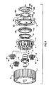
- Fig. 1 is a rear perspective exploded view.
- the inventive transfer case 100 comprises sprocket 1.
- a hub 4 is rotationally engaged with sprocket 1 through needle bearing 5.
- Hub 4 is rotationally engaged with planetary cage 2 through a ball bearing 16, see Fig. 2 .
- Sprocket surface 10 has a toothed profile for engaging a toothed belt (not shown). Toothed belts are known in the art.
- Sprocket 1 is typically the input member, although it can function as the output member as well.
- Hub 4 is typically the output member, although it can function as the input member as well.
- Planetary gears 8 are rotatingly engaged with and are disposed in an annular fashion about planetary cage 2.
- Each planetary gear 8 comprises a gear having a relatively larger first diameter 81 and a relatively smaller second diameter 82. Five planetary gears are used in this embodiment.
- Gears 82 engage gear 41 on hub 4.
- Gears 81 engage ring gear 110 on an inner surface of sprocket 1.
- Planetary cage 2 and gears 8 comprise the planetary gear portion. Planetary cage 2 is rotationally engaged with sprocket 1 through bearing 11.
- Shifter spring 21 is disposed between hub 4 and shift ring 13. Spring 21 urges shift ring 13 into contact with movable cam 20. Shifter spring 21 is a coil spring.
- Outer disc 12 is fixedly connected to sprocket 1 using bolts 101.
- Shift ring gear 130 cooperatively engages gear 120 on outer disc 12.
- Cam 20 comprises a ratchet portion 201. Cam 20 also comprises lever 200 which engages an actuator cable (not shown) such as a Bowden cable.
- actuator cable not shown
- Cam 20 slidingly and rotationally engages bearing plate 19.
- Camming member 202 cooperatively engages camming body 190.
- Fig. 2 is a front perspective exploded view.
- Ratchet portion 201 cooperatively engages ratchet portion 42 on planetary cage 2.
- Hub 4 engages planetary cage 2 through bearing 16.
- Ring gear 210 is fixedly disposed on an inward surface of planetary cage 2.
- Fig. 3 is a side view. Camming body 190 slidingly engages camming member 202. Cam 20 rotates through a range of approximately 25° with respect to bearing plate 19 by application of a force to lever 200. Fig. 3 shows cam 20 in the fully retracted position. In operation cam 20 rotationally moves in direction D about the axis of rotation A-A as shown in Fig. 1 .
- Fig. 4 is a front view. Toothed surface 10 engages a toothed belt (not shown).
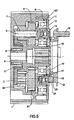
- Fig. 5 is section 5-5 in Fig. 4 .
- Rivets or bolts 14 may be used to connect the bearing plate 19 to a mounting surface such as a vehicle engine (not shown).
- Bolts 101 connect the outer disc 12 to sprocket 1.
- Hub 4 connects to an output drive shaft (not shown). The drive shaft may be connected to a vehicle axle.
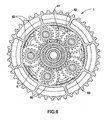
- Fig. 6 is section 6-6 in Fig. 3 .
- Gears 82 engage hub gear 41.
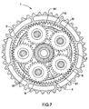
- Fig. 7 is section 7-7 in Fig. 3 .
- Gears 81 engage sprocket ring gear 110.
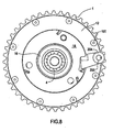
- Fig. 8 is a rear view.
- Actuator engaging portion 204 is connected to an actuator by a cable (not shown).
- Lever 200 moves through an arc of approximately 25° between each position of operation, namely, forward and reverse.
- a drive shaft (not shown) is connected to hub 4.
- a belt (not shown) is connected to input member sprocket 1 which transmits a torque to sprocket 1 causing it to rotate.
- cam 20 is retracted meaning that camming member 202 and camming body 190 are in the relative positions shown in Fig. 3 .
- the retracted position of cam 20 allows spring 21 to urge shift ring 13 toward cam 20, causing gear 130 to engage gear 120 of outer disc 12.
- Gear 130 of shift ring 13 is also simultaneously engaged with ring gear 210.
- This engagement causes planetary cage 2 to rotate in locked relation with outer disc 12 and sprocket 1.
- sprocket 1 outer disc 12, shift ring 13 and planetary cage 2 comprise and are driven as a single unit because there is no relative rotation between planetary cage 2 and sprocket 1.
- gears 8 Since planetary cage 2 rotates in unison with sprocket 1, gears 8 do not rotate relative to ring gear 110. Therefore, gears 8 drive gear 41 and thereby hub 4 at the same rotational speed and direction as sprocket 1. Hence, in the normal mode the planetary cage 2 rotates in unison with the sprocket 1, thereby, the output member hub 4 rotates at the same speed and direction as the input member sprocket 1.
- cam 20 In reverse mode cam 20 is actuated, causing it to partially rotate with respect to bearing plate 19. Partial rotation causes camming body 190 and camming member 202 to move relative to each other. Such movement causes cam 20 to move axially away from bearing plate 19, which in turn causes gear 130 to disengage from gear 120. This "breaks" the mechanical driving connection between the planetary cage 2 (gear 210) and the sprocket 1 (gear 120). This also causes ratchet teeth 201 to come into contact with ratchet teeth 42. Since cam 20 only rotates partially through approximately 25° during actuation, this has the overall effect of stopping rotation of planetary cage 2. However, sprocket 1 still rotates because gear 130 and gear 120 are disengaged. The rotation of the planetary gear portion planetary cage 2 is stopped when the cam 20 is engaged with the planetary cage 2.
- the drive ratio between the input member (sprocket 1) and the output member (hub 4) is approximately 1.28:1.
- gear 8 comprised only one gear then hub 4 would speed up when in reverse.
- the increase of speed would equal the ratio between the number of teeth of the sprocket gear 110, and the hub gear 41, which in this case, for example, is 75:35 ( 2.14 :1).
- a single-gear planetary gear (8) would only be a torque transmitting/reversing medium, consequently its number of teeth would play no role in this ratio.
- gear 8 has a larger diameter gear 81 and a smaller diameter gear 82, and each is engaged with gear 110 and gear 41 respectively, this reduces the transmitted speed by the gear ratio of:
- the inventive device achieves reverse operation without significant change to the output speed in reverse as compared to the output speed in forward. This minimizes speed surges that might otherwise be caused by small throttle inputs using other transmissions with larger ratios.
- the drive ratio may be adjusted depending upon the relative diameters of gears 81 and 82.
- the input member and output members may also be reversed so that the input member is now hub 4 and the output member is now sprocket 1 with equal operating success.
Landscapes
- Engineering & Computer Science (AREA)
- General Engineering & Computer Science (AREA)
- Mechanical Engineering (AREA)
- Chemical & Material Sciences (AREA)
- Combustion & Propulsion (AREA)
- Transportation (AREA)
- Transmission Devices (AREA)
- Retarders (AREA)
Abstract
Description
- The invention relates to a reverse sprocket transfer case having a moveable cam member selectively engagable with a planetary gear portion, whereby the rotation of the planetary gear portion is stopped when the cam member is engaged with the planetary gear portion, thereby reversing the rotational direction of an output member.
- All terrain vehicles (ATV's) have been known for many years. They comprise an engine and transmission used to propel the vehicle over rough terrain. The engine generally comprises a two stroke or four stroke arrangement with a transmission attached. The transmission is generally similar those used on motorcycles, particularly since the engines are also usually derived from motorcycles.
- One drawback for ATV's is the ability to back the vehicle should the need arise. Transmissions are available for this function, however, they can be costly, bulky and complex. Complexity can adversely affect performance and reliability since component failure is often related to the number of moving parts. The size of the reversing transmission can be a limiting factor in vehicle design as well. A large, heavy transmission is not desirable when total vehicle weight is in the range of only 400-500 pounds.
-
U.S. 6,742,618 (2004 ) discloses a reduction drive system including planetary gears. In an alternate embodiment, a reversing unit is provided.U.S. 4,150,590 discloses a transfer case according to the preamble ofclaim 1. - What is needed is a reverse sprocket transfer case having a moveable cam member selectively engagable with a planetary gear portion, whereby the rotation of the planetary gear portion is stopped when the cam member is engaged with the planetary gear portion. The present invention meets this need.
- The primary aspect of the invention is to provide a reverse sprocket transfer case having a moveable cam member selectively engagable with a planetary gear portion, whereby the rotation of the planetary gear portion is stopped when the cam member is engaged with the planetary gear portion.
- Other aspects of the invention will be pointed out or made obvious by the following description of the invention and the accompanying drawings.
- The invention comprises a transfer case as recited in the claims.
- The accompanying drawings, which are incorporated in and form a part of the specification, illustrate preferred embodiments of the present invention, and together with a description, serve to explain the principles of the invention.
-
Fig. 1 is a rear perspective exploded view. -
Fig. 2 is a front perspective exploded view. -
Fig. 3 is a side view. -
Fig. 4 is a front view. -
Fig. 5 is section 5-5 inFig. 4 . -
Fig. 6 is section 6-6 inFig. 3 . -
Fig. 7 is section 7-7 inFig. 3 . -
Fig. 8 is a rear view. -
Fig. 1 is a rear perspective exploded view. Theinventive transfer case 100 comprisessprocket 1. Ahub 4 is rotationally engaged withsprocket 1 through needle bearing 5.Hub 4 is rotationally engaged withplanetary cage 2 through a ball bearing 16, seeFig. 2 . Sprocketsurface 10 has a toothed profile for engaging a toothed belt (not shown). Toothed belts are known in the art. Sprocket 1 is typically the input member, although it can function as the output member as well.Hub 4 is typically the output member, although it can function as the input member as well. -
Planetary gears 8 are rotatingly engaged with and are disposed in an annular fashion aboutplanetary cage 2. Eachplanetary gear 8 comprises a gear having a relatively largerfirst diameter 81 and a relatively smallersecond diameter 82. Five planetary gears are used in this embodiment. Gears 82 engagegear 41 onhub 4. Gears 81 engagering gear 110 on an inner surface ofsprocket 1. -
Planetary cage 2 andgears 8 comprise the planetary gear portion.Planetary cage 2 is rotationally engaged withsprocket 1 through bearing 11. - Shifter
spring 21 is disposed betweenhub 4 andshift ring 13.Spring 21urges shift ring 13 into contact withmovable cam 20. Shifterspring 21 is a coil spring. -
Outer disc 12 is fixedly connected tosprocket 1 usingbolts 101.Shift ring gear 130 cooperatively engagesgear 120 onouter disc 12. -
Cam 20 comprises aratchet portion 201.Cam 20 also compriseslever 200 which engages an actuator cable (not shown) such as a Bowden cable. -
Cam 20 slidingly and rotationally engages bearingplate 19. Cammingmember 202 cooperatively engagescamming body 190. -
Fig. 2 is a front perspective exploded view.Ratchet portion 201 cooperatively engagesratchet portion 42 onplanetary cage 2.Hub 4 engagesplanetary cage 2 through bearing 16. -
Ring gear 210 is fixedly disposed on an inward surface ofplanetary cage 2. -
Fig. 3 is a side view. Cammingbody 190 slidingly engagescamming member 202.Cam 20 rotates through a range of approximately 25° with respect to bearingplate 19 by application of a force to lever 200.Fig. 3 shows cam 20 in the fully retracted position. Inoperation cam 20 rotationally moves in direction D about the axis of rotation A-A as shown inFig. 1 . -
Fig. 4 is a front view.Toothed surface 10 engages a toothed belt (not shown). -
Fig. 5 is section 5-5 inFig. 4 . Rivets orbolts 14 may be used to connect the bearingplate 19 to a mounting surface such as a vehicle engine (not shown).Bolts 101 connect theouter disc 12 tosprocket 1.Hub 4 connects to an output drive shaft (not shown). The drive shaft may be connected to a vehicle axle. -
Fig. 6 is section 6-6 inFig. 3 .Gears 82 engagehub gear 41. -
Fig. 7 is section 7-7 inFig. 3 .Gears 81 engagesprocket ring gear 110. -
Fig. 8 is a rear view.Actuator engaging portion 204 is connected to an actuator by a cable (not shown).Lever 200 moves through an arc of approximately 25° between each position of operation, namely, forward and reverse. - In normal mode operation a drive shaft (not shown) is connected to
hub 4. A belt (not shown) is connected to inputmember sprocket 1 which transmits a torque tosprocket 1 causing it to rotate. - In this
mode cam 20 is retracted meaning thatcamming member 202 andcamming body 190 are in the relative positions shown inFig. 3 . The retracted position ofcam 20 allowsspring 21 to urgeshift ring 13 towardcam 20, causinggear 130 to engagegear 120 ofouter disc 12.Gear 130 ofshift ring 13 is also simultaneously engaged withring gear 210. This engagement causesplanetary cage 2 to rotate in locked relation withouter disc 12 andsprocket 1. In other words, in thismode sprocket 1,outer disc 12,shift ring 13 andplanetary cage 2 comprise and are driven as a single unit because there is no relative rotation betweenplanetary cage 2 andsprocket 1. Sinceplanetary cage 2 rotates in unison withsprocket 1, gears 8 do not rotate relative toring gear 110. Therefore, gears 8drive gear 41 and therebyhub 4 at the same rotational speed and direction assprocket 1. Hence, in the normal mode theplanetary cage 2 rotates in unison with thesprocket 1, thereby, theoutput member hub 4 rotates at the same speed and direction as theinput member sprocket 1. - In
reverse mode cam 20 is actuated, causing it to partially rotate with respect to bearingplate 19. Partial rotation causescamming body 190 andcamming member 202 to move relative to each other. Such movement causescam 20 to move axially away from bearingplate 19, which in turn causesgear 130 to disengage fromgear 120. This "breaks" the mechanical driving connection between the planetary cage 2 (gear 210) and the sprocket 1 (gear 120). This also causes ratchetteeth 201 to come into contact withratchet teeth 42. Sincecam 20 only rotates partially through approximately 25° during actuation, this has the overall effect of stopping rotation ofplanetary cage 2. However,sprocket 1 still rotates becausegear 130 andgear 120 are disengaged. The rotation of the planetary gear portionplanetary cage 2 is stopped when thecam 20 is engaged with theplanetary cage 2. - Once
planetary cage 2 is stopped from rotating, the engagement ofgears 81 andgear 110 cause gears 8 to rotate. Rotation ofgears 8 causes gears 82 to rotate, in turn drivinghub gear 41. However,hub 4 rotates in the direction opposite the direction of rotation ofsprocket 1 due to the fixed position ofgears 8. Rotation ofhub 4 within stationaryplanetary cage 2 is made possible by bearing 5 andbearing 16. - In the reverse mode the drive ratio between the input member (sprocket 1) and the output member (hub 4) is approximately 1.28:1. This is because if, for example,
gear 8 comprised only one gear thenhub 4 would speed up when in reverse. The increase of speed would equal the ratio between the number of teeth of thesprocket gear 110, and thehub gear 41, which in this case, for example, is 75:35 (2.14:1). A single-gear planetary gear (8) would only be a torque transmitting/reversing medium, consequently its number of teeth would play no role in this ratio. However, sincegear 8 has alarger diameter gear 81 and asmaller diameter gear 82, and each is engaged withgear 110 andgear 41 respectively, this reduces the transmitted speed by the gear ratio of: - (# of teeth in gear 81):(# of teeth in gear 82) which in this case by way of example is: 15:25 = 0.6.
- Consequently the total speed change/increase in reverse mode between
input sprocket 1 andoutput hub 4 is:
- This means the overall drive ratio in reverse mode is 1.28:1. The inventive device achieves reverse operation without significant change to the output speed in reverse as compared to the output speed in forward. This minimizes speed surges that might otherwise be caused by small throttle inputs using other transmissions with larger ratios.
- The drive ratio may be adjusted depending upon the relative diameters of
gears - The input member and output members may also be reversed so that the input member is now
hub 4 and the output member is now sprocket 1 with equal operating success. - Although forms of the invention have been described herein, it will be obvious to those skilled in the art that variations may be made in the construction and relation of parts and method without departing from the scope of the invention described herein.
Claims (3)
- A transfer case comprising:a rotational input member (1);a rotational output member (4);a rotational planetary gear portion (2) mechanically engaged between the input member (1) and the output member (4);a moveable cam member (20) selectively engagable with the planetary gear portion (2), whereby the rotation of the planetary gear portion (2) is stopped when the cam member (20) is engaged with the planetary gear portion (2);the rotational direction of the output member (4) is in the same direction as the input member (1) when the cam member (20) is not engaged with the planetary gear portion (2); andthe rotational direction of the output member (4) is opposite the rotational direction of the input member (1) when the cam member (20) is engaged with the planetary gear portion (2); characterised in that :a cam member ratchet portion (201) engages a ratchet portion (42) of the planetary gear portion (2).
- The transfer case as in claim 1 further comprising a gear (130) for selectively engaging the planetary gear portion (2) with the output member (4) whereby the planetary gear portion (2) and the output member (4) rotate in locked relation.
- The transfer case as in claim 1, wherein an output drive ratio between the input member (1) and the output member (4) is approximately the same for either forward mode or reverse mode.
Applications Claiming Priority (2)
| Application Number | Priority Date | Filing Date | Title |
|---|---|---|---|
| US11/888,743 US7815542B2 (en) | 2007-08-02 | 2007-08-02 | Reverse sprocket transfer case |
| PCT/US2008/007814 WO2009017551A2 (en) | 2007-08-02 | 2008-06-23 | Reverse sprocket transfer case |
Publications (2)
| Publication Number | Publication Date |
|---|---|
| EP2174038A2 EP2174038A2 (en) | 2010-04-14 |
| EP2174038B1 true EP2174038B1 (en) | 2012-08-08 |
Family
ID=39832029
Family Applications (1)
| Application Number | Title | Priority Date | Filing Date |
|---|---|---|---|
| EP08768733A Not-in-force EP2174038B1 (en) | 2007-08-02 | 2008-06-23 | Reverse sprocket transfer case |
Country Status (6)
| Country | Link |
|---|---|
| US (1) | US7815542B2 (en) |
| EP (1) | EP2174038B1 (en) |
| JP (1) | JP5426549B2 (en) |
| KR (1) | KR101150092B1 (en) |
| BR (1) | BRPI0814453A2 (en) |
| WO (1) | WO2009017551A2 (en) |
Families Citing this family (20)
| Publication number | Priority date | Publication date | Assignee | Title |
|---|---|---|---|---|
| US7703353B2 (en) * | 2006-11-28 | 2010-04-27 | Ford Global Technologies, Llc | Drive unit connected to a transmission output for producing forward and reverse device |
| JP5065127B2 (en) * | 2008-03-31 | 2012-10-31 | 本田技研工業株式会社 | Saddle-ride type vehicle with forward / reverse switching mechanism |
| US8529393B2 (en) * | 2010-01-20 | 2013-09-10 | Tai-Her Yang | Lockable or releasable wheel system with bidirectional input and one-way output |
| US8201839B2 (en) * | 2010-02-03 | 2012-06-19 | Tai-Her Yang | Bicycle with bidirectional input and one-way output |
| US8272988B2 (en) * | 2010-02-12 | 2012-09-25 | Tai-Her Yang | Retrograde torque limit bicycle with bidirectional input and one-way output |
| BRMU9100113U2 (en) * | 2011-01-14 | 2013-05-28 | Laury Grandi | reversing cube |
| GB2486513B (en) * | 2011-07-15 | 2013-07-10 | Arrma Durango Ltd | Gearbox |
| US8777795B2 (en) * | 2012-04-26 | 2014-07-15 | Phil Schwarz | Device to reverse direction of a unidirectional powered drive |
| JP2014016432A (en) * | 2012-07-06 | 2014-01-30 | Canon Inc | Drive device and image forming apparatus |
| US8926467B2 (en) | 2013-03-08 | 2015-01-06 | Harley-Davidson Motor Company Group, LLC | Transmission with reverse drive assembly |
| JP6184279B2 (en) * | 2013-09-30 | 2017-08-23 | キヤノン株式会社 | Driving force switching mechanism and image forming apparatus |
| JP6184280B2 (en) * | 2013-09-30 | 2017-08-23 | キヤノン株式会社 | Driving force switching mechanism and image forming apparatus |
| US9783365B2 (en) | 2013-09-30 | 2017-10-10 | Canon Kabushiki Kaisha | Driving force transmission device and image-forming apparatus |
| US9739365B2 (en) * | 2014-10-14 | 2017-08-22 | Richard D. Yelvington | Metadrive planetary gear drive system |
| USD765551S1 (en) * | 2015-02-23 | 2016-09-06 | Baker, Inc. | Compensator sprocket |
| JP6752008B2 (en) * | 2015-10-23 | 2020-09-09 | アズビル株式会社 | Manipulator |
| JP6752009B2 (en) * | 2015-10-23 | 2020-09-09 | アズビル株式会社 | Manipulator |
| US10184545B2 (en) * | 2016-08-03 | 2019-01-22 | Hamilton Sundstrand Corporation | Power drive unit with dual gear ratio mechanism |
| JP6400158B2 (en) * | 2017-07-26 | 2018-10-03 | キヤノン株式会社 | Driving force switching mechanism and image forming apparatus |
| WO2021087101A1 (en) | 2019-10-29 | 2021-05-06 | Polaris Industries Inc. | Reverse gear system for vehicle |
Family Cites Families (16)
| Publication number | Priority date | Publication date | Assignee | Title |
|---|---|---|---|---|
| US3005360A (en) * | 1960-10-10 | 1961-10-24 | Internatioanl Harvester Compan | Reversing mechanism |
| US3217564A (en) * | 1963-02-28 | 1965-11-16 | Charles L Smith | Reversible drive for power tools |
| US4083421A (en) * | 1976-12-06 | 1978-04-11 | Horn Ronald L Van | Two speed motorcycle hub transmission |
| US4150590A (en) | 1977-07-29 | 1979-04-24 | Chrysler Corporation | Drive couplings and clutches |
| US4502353A (en) * | 1983-01-26 | 1985-03-05 | Gaston Beaudoin | Carrier braked forward and reverse planetary transmission |
| US4922790A (en) * | 1988-01-27 | 1990-05-08 | Abbott Harold F | Dynamic phase adjuster |
| JPH0431356U (en) * | 1990-07-10 | 1992-03-13 | ||
| US5435583A (en) | 1993-08-09 | 1995-07-25 | Foster, Jr.; James P. | Clutch operated, bi-directional, bicycle gear box |
| DE9316748U1 (en) | 1993-11-03 | 1994-03-31 | Metzinger, Arnold, 82239 Alling | Bicycle with gear shift |
| US5951434A (en) * | 1998-08-31 | 1999-09-14 | Richards; Victor | Planetary gear transmission for a light vehicle such as a motorcycle |
| US6742618B2 (en) | 2000-03-07 | 2004-06-01 | Arctic Cat, Inc. | Snowmobile planetary drive system |
| JP3946437B2 (en) * | 2000-12-25 | 2007-07-18 | 株式会社日立製作所 | Clutch device and power transmission device |
| JP4147788B2 (en) * | 2002-03-05 | 2008-09-10 | トヨタ自動車株式会社 | Continuously variable transmission for vehicle |
| JP2005265019A (en) * | 2004-03-17 | 2005-09-29 | Toyota Motor Corp | Transmission |
| US7390280B2 (en) | 2005-05-25 | 2008-06-24 | Hobbico, Inc. | Model vehicle transmission system |
| US7311636B1 (en) * | 2005-07-12 | 2007-12-25 | Regula Peter P | Reverse attachments for motorcycles |
-
2007
- 2007-08-02 US US11/888,743 patent/US7815542B2/en not_active Expired - Fee Related
-
2008
- 2008-06-23 JP JP2010519185A patent/JP5426549B2/en not_active Expired - Fee Related
- 2008-06-23 WO PCT/US2008/007814 patent/WO2009017551A2/en active Application Filing
- 2008-06-23 KR KR1020107003933A patent/KR101150092B1/en not_active IP Right Cessation
- 2008-06-23 BR BRPI0814453-2A2A patent/BRPI0814453A2/en not_active Application Discontinuation
- 2008-06-23 EP EP08768733A patent/EP2174038B1/en not_active Not-in-force
Also Published As
| Publication number | Publication date |
|---|---|
| WO2009017551A2 (en) | 2009-02-05 |
| BRPI0814453A2 (en) | 2015-01-06 |
| KR101150092B1 (en) | 2012-06-01 |
| KR20100038451A (en) | 2010-04-14 |
| JP2010535319A (en) | 2010-11-18 |
| JP5426549B2 (en) | 2014-02-26 |
| WO2009017551A3 (en) | 2009-07-23 |
| EP2174038A2 (en) | 2010-04-14 |
| US7815542B2 (en) | 2010-10-19 |
| US20090036260A1 (en) | 2009-02-05 |
Similar Documents
| Publication | Publication Date | Title |
|---|---|---|
| EP2174038B1 (en) | Reverse sprocket transfer case | |
| US7309067B2 (en) | Continuously variable transmission | |
| US8408086B2 (en) | Automated shift control device and straddle-type vehicle equipped with the same | |
| US8276473B2 (en) | Sift-drum apparatus and four wheeled vehicle with the same | |
| WO2009030948A2 (en) | Continuously variable transmission | |
| US5280731A (en) | Constant-mesh transmission with a chain drive and double disconnect reverse | |
| US9194485B2 (en) | Shift system for power transfer unit having dual sector shift actuator | |
| EP0851149A1 (en) | A planetary gear mechanism | |
| EP2481958A1 (en) | Vehicle transmission | |
| US5637046A (en) | Variable ratio transmission system and clutch mechanism therefor | |
| EP1205337B1 (en) | Differential limiting device for a differential device | |
| JP3201988B2 (en) | Power transmission mechanism | |
| JP3001486B2 (en) | Gear type transmission | |
| CA2304428C (en) | Torque converter drive and countershaft transmission drive combination | |
| JP3281380B2 (en) | Modular transmission device and power unit equipped with it | |
| JPH06294421A (en) | Mechanism for preventing follow-up rotation at clutch neutral position | |
| JPH0799193B2 (en) | Gear change device | |
| EP2399046B1 (en) | Continuously variable transmission system | |
| JP3221464B2 (en) | Side clutch link mechanism | |
| TW202028023A (en) | Transmission unit for motor vehicles with reverse drive and motor vehicle comprising the transmission unit | |
| JPH0813660B2 (en) | Mobile power transmission device for mobile agricultural machinery | |
| JPS63246543A (en) | Clutch drum for automatic transmission | |
| JPH0799194B2 (en) | Gear change device | |
| KR19990003456U (en) | Neutral slower of manual transmission for automobile |
Legal Events
| Date | Code | Title | Description |
|---|---|---|---|
| PUAI | Public reference made under article 153(3) epc to a published international application that has entered the european phase |
Free format text: ORIGINAL CODE: 0009012 |
|
| 17P | Request for examination filed |
Effective date: 20100204 |
|
| AK | Designated contracting states |
Kind code of ref document: A2 Designated state(s): AT BE BG CH CY CZ DE DK EE ES FI FR GB GR HR HU IE IS IT LI LT LU LV MC MT NL NO PL PT RO SE SI SK TR |
|
| AX | Request for extension of the european patent |
Extension state: AL BA MK RS |
|
| 17Q | First examination report despatched |
Effective date: 20110527 |
|
| GRAP | Despatch of communication of intention to grant a patent |
Free format text: ORIGINAL CODE: EPIDOSNIGR1 |
|
| RIC1 | Information provided on ipc code assigned before grant |
Ipc: F16H 3/60 20060101AFI20120208BHEP |
|
| DAX | Request for extension of the european patent (deleted) | ||
| GRAS | Grant fee paid |
Free format text: ORIGINAL CODE: EPIDOSNIGR3 |
|
| GRAA | (expected) grant |
Free format text: ORIGINAL CODE: 0009210 |
|
| AK | Designated contracting states |
Kind code of ref document: B1 Designated state(s): AT BE BG CH CY CZ DE DK EE ES FI FR GB GR HR HU IE IS IT LI LT LU LV MC MT NL NO PL PT RO SE SI SK TR |
|
| REG | Reference to a national code |
Ref country code: GB Ref legal event code: FG4D |
|
| REG | Reference to a national code |
Ref country code: CH Ref legal event code: EP Ref country code: AT Ref legal event code: REF Ref document number: 569948 Country of ref document: AT Kind code of ref document: T Effective date: 20120815 |
|
| REG | Reference to a national code |
Ref country code: IE Ref legal event code: FG4D |
|
| REG | Reference to a national code |
Ref country code: DE Ref legal event code: R096 Ref document number: 602008017842 Country of ref document: DE Effective date: 20121004 |
|
| REG | Reference to a national code |
Ref country code: NL Ref legal event code: VDEP Effective date: 20120808 |
|
| REG | Reference to a national code |
Ref country code: AT Ref legal event code: MK05 Ref document number: 569948 Country of ref document: AT Kind code of ref document: T Effective date: 20120808 |
|
| REG | Reference to a national code |
Ref country code: LT Ref legal event code: MG4D Effective date: 20120808 |
|
| PG25 | Lapsed in a contracting state [announced via postgrant information from national office to epo] |
Ref country code: CY Free format text: LAPSE BECAUSE OF FAILURE TO SUBMIT A TRANSLATION OF THE DESCRIPTION OR TO PAY THE FEE WITHIN THE PRESCRIBED TIME-LIMIT Effective date: 20120808 Ref country code: IS Free format text: LAPSE BECAUSE OF FAILURE TO SUBMIT A TRANSLATION OF THE DESCRIPTION OR TO PAY THE FEE WITHIN THE PRESCRIBED TIME-LIMIT Effective date: 20121208 Ref country code: HR Free format text: LAPSE BECAUSE OF FAILURE TO SUBMIT A TRANSLATION OF THE DESCRIPTION OR TO PAY THE FEE WITHIN THE PRESCRIBED TIME-LIMIT Effective date: 20120808 Ref country code: NO Free format text: LAPSE BECAUSE OF FAILURE TO SUBMIT A TRANSLATION OF THE DESCRIPTION OR TO PAY THE FEE WITHIN THE PRESCRIBED TIME-LIMIT Effective date: 20121108 Ref country code: LT Free format text: LAPSE BECAUSE OF FAILURE TO SUBMIT A TRANSLATION OF THE DESCRIPTION OR TO PAY THE FEE WITHIN THE PRESCRIBED TIME-LIMIT Effective date: 20120808 Ref country code: FI Free format text: LAPSE BECAUSE OF FAILURE TO SUBMIT A TRANSLATION OF THE DESCRIPTION OR TO PAY THE FEE WITHIN THE PRESCRIBED TIME-LIMIT Effective date: 20120808 Ref country code: AT Free format text: LAPSE BECAUSE OF FAILURE TO SUBMIT A TRANSLATION OF THE DESCRIPTION OR TO PAY THE FEE WITHIN THE PRESCRIBED TIME-LIMIT Effective date: 20120808 |
|
| PG25 | Lapsed in a contracting state [announced via postgrant information from national office to epo] |
Ref country code: GR Free format text: LAPSE BECAUSE OF FAILURE TO SUBMIT A TRANSLATION OF THE DESCRIPTION OR TO PAY THE FEE WITHIN THE PRESCRIBED TIME-LIMIT Effective date: 20121109 Ref country code: SI Free format text: LAPSE BECAUSE OF FAILURE TO SUBMIT A TRANSLATION OF THE DESCRIPTION OR TO PAY THE FEE WITHIN THE PRESCRIBED TIME-LIMIT Effective date: 20120808 Ref country code: BE Free format text: LAPSE BECAUSE OF FAILURE TO SUBMIT A TRANSLATION OF THE DESCRIPTION OR TO PAY THE FEE WITHIN THE PRESCRIBED TIME-LIMIT Effective date: 20120808 Ref country code: PT Free format text: LAPSE BECAUSE OF FAILURE TO SUBMIT A TRANSLATION OF THE DESCRIPTION OR TO PAY THE FEE WITHIN THE PRESCRIBED TIME-LIMIT Effective date: 20121210 Ref country code: LV Free format text: LAPSE BECAUSE OF FAILURE TO SUBMIT A TRANSLATION OF THE DESCRIPTION OR TO PAY THE FEE WITHIN THE PRESCRIBED TIME-LIMIT Effective date: 20120808 Ref country code: SE Free format text: LAPSE BECAUSE OF FAILURE TO SUBMIT A TRANSLATION OF THE DESCRIPTION OR TO PAY THE FEE WITHIN THE PRESCRIBED TIME-LIMIT Effective date: 20120808 Ref country code: PL Free format text: LAPSE BECAUSE OF FAILURE TO SUBMIT A TRANSLATION OF THE DESCRIPTION OR TO PAY THE FEE WITHIN THE PRESCRIBED TIME-LIMIT Effective date: 20120808 |
|
| PG25 | Lapsed in a contracting state [announced via postgrant information from national office to epo] |
Ref country code: NL Free format text: LAPSE BECAUSE OF FAILURE TO SUBMIT A TRANSLATION OF THE DESCRIPTION OR TO PAY THE FEE WITHIN THE PRESCRIBED TIME-LIMIT Effective date: 20120808 |
|
| PG25 | Lapsed in a contracting state [announced via postgrant information from national office to epo] |
Ref country code: RO Free format text: LAPSE BECAUSE OF FAILURE TO SUBMIT A TRANSLATION OF THE DESCRIPTION OR TO PAY THE FEE WITHIN THE PRESCRIBED TIME-LIMIT Effective date: 20120808 Ref country code: DK Free format text: LAPSE BECAUSE OF FAILURE TO SUBMIT A TRANSLATION OF THE DESCRIPTION OR TO PAY THE FEE WITHIN THE PRESCRIBED TIME-LIMIT Effective date: 20120808 Ref country code: EE Free format text: LAPSE BECAUSE OF FAILURE TO SUBMIT A TRANSLATION OF THE DESCRIPTION OR TO PAY THE FEE WITHIN THE PRESCRIBED TIME-LIMIT Effective date: 20120808 Ref country code: ES Free format text: LAPSE BECAUSE OF FAILURE TO SUBMIT A TRANSLATION OF THE DESCRIPTION OR TO PAY THE FEE WITHIN THE PRESCRIBED TIME-LIMIT Effective date: 20121119 Ref country code: CZ Free format text: LAPSE BECAUSE OF FAILURE TO SUBMIT A TRANSLATION OF THE DESCRIPTION OR TO PAY THE FEE WITHIN THE PRESCRIBED TIME-LIMIT Effective date: 20120808 |
|
| PG25 | Lapsed in a contracting state [announced via postgrant information from national office to epo] |
Ref country code: SK Free format text: LAPSE BECAUSE OF FAILURE TO SUBMIT A TRANSLATION OF THE DESCRIPTION OR TO PAY THE FEE WITHIN THE PRESCRIBED TIME-LIMIT Effective date: 20120808 |
|
| PLBE | No opposition filed within time limit |
Free format text: ORIGINAL CODE: 0009261 |
|
| STAA | Information on the status of an ep patent application or granted ep patent |
Free format text: STATUS: NO OPPOSITION FILED WITHIN TIME LIMIT |
|
| 26N | No opposition filed |
Effective date: 20130510 |
|
| PG25 | Lapsed in a contracting state [announced via postgrant information from national office to epo] |
Ref country code: BG Free format text: LAPSE BECAUSE OF FAILURE TO SUBMIT A TRANSLATION OF THE DESCRIPTION OR TO PAY THE FEE WITHIN THE PRESCRIBED TIME-LIMIT Effective date: 20121108 |
|
| REG | Reference to a national code |
Ref country code: DE Ref legal event code: R097 Ref document number: 602008017842 Country of ref document: DE Effective date: 20130510 |
|
| PG25 | Lapsed in a contracting state [announced via postgrant information from national office to epo] |
Ref country code: MC Free format text: LAPSE BECAUSE OF FAILURE TO SUBMIT A TRANSLATION OF THE DESCRIPTION OR TO PAY THE FEE WITHIN THE PRESCRIBED TIME-LIMIT Effective date: 20120808 |
|
| REG | Reference to a national code |
Ref country code: CH Ref legal event code: PL |
|
| REG | Reference to a national code |
Ref country code: IE Ref legal event code: MM4A |
|
| PG25 | Lapsed in a contracting state [announced via postgrant information from national office to epo] |
Ref country code: CH Free format text: LAPSE BECAUSE OF NON-PAYMENT OF DUE FEES Effective date: 20130630 Ref country code: LI Free format text: LAPSE BECAUSE OF NON-PAYMENT OF DUE FEES Effective date: 20130630 Ref country code: IE Free format text: LAPSE BECAUSE OF NON-PAYMENT OF DUE FEES Effective date: 20130623 |
|
| PG25 | Lapsed in a contracting state [announced via postgrant information from national office to epo] |
Ref country code: MT Free format text: LAPSE BECAUSE OF FAILURE TO SUBMIT A TRANSLATION OF THE DESCRIPTION OR TO PAY THE FEE WITHIN THE PRESCRIBED TIME-LIMIT Effective date: 20120808 |
|
| PG25 | Lapsed in a contracting state [announced via postgrant information from national office to epo] |
Ref country code: TR Free format text: LAPSE BECAUSE OF FAILURE TO SUBMIT A TRANSLATION OF THE DESCRIPTION OR TO PAY THE FEE WITHIN THE PRESCRIBED TIME-LIMIT Effective date: 20120808 |
|
| PG25 | Lapsed in a contracting state [announced via postgrant information from national office to epo] |
Ref country code: LU Free format text: LAPSE BECAUSE OF NON-PAYMENT OF DUE FEES Effective date: 20130623 Ref country code: HU Free format text: LAPSE BECAUSE OF FAILURE TO SUBMIT A TRANSLATION OF THE DESCRIPTION OR TO PAY THE FEE WITHIN THE PRESCRIBED TIME-LIMIT; INVALID AB INITIO Effective date: 20080623 |
|
| REG | Reference to a national code |
Ref country code: FR Ref legal event code: PLFP Year of fee payment: 9 |
|
| REG | Reference to a national code |
Ref country code: FR Ref legal event code: PLFP Year of fee payment: 10 |
|
| PGFP | Annual fee paid to national office [announced via postgrant information from national office to epo] |
Ref country code: FR Payment date: 20170627 Year of fee payment: 10 Ref country code: GB Payment date: 20170627 Year of fee payment: 10 |
|
| PGFP | Annual fee paid to national office [announced via postgrant information from national office to epo] |
Ref country code: IT Payment date: 20170622 Year of fee payment: 10 |
|
| PGFP | Annual fee paid to national office [announced via postgrant information from national office to epo] |
Ref country code: DE Payment date: 20170628 Year of fee payment: 10 |
|
| REG | Reference to a national code |
Ref country code: DE Ref legal event code: R119 Ref document number: 602008017842 Country of ref document: DE |
|
| GBPC | Gb: european patent ceased through non-payment of renewal fee |
Effective date: 20180623 |
|
| PG25 | Lapsed in a contracting state [announced via postgrant information from national office to epo] |
Ref country code: FR Free format text: LAPSE BECAUSE OF NON-PAYMENT OF DUE FEES Effective date: 20180630 Ref country code: GB Free format text: LAPSE BECAUSE OF NON-PAYMENT OF DUE FEES Effective date: 20180623 Ref country code: IT Free format text: LAPSE BECAUSE OF NON-PAYMENT OF DUE FEES Effective date: 20180623 Ref country code: DE Free format text: LAPSE BECAUSE OF NON-PAYMENT OF DUE FEES Effective date: 20190101 |