EP2173117A1 - Relay station, mobile station, and relay transmission method in mobile communication system - Google Patents
Relay station, mobile station, and relay transmission method in mobile communication system Download PDFInfo
- Publication number
- EP2173117A1 EP2173117A1 EP08790237A EP08790237A EP2173117A1 EP 2173117 A1 EP2173117 A1 EP 2173117A1 EP 08790237 A EP08790237 A EP 08790237A EP 08790237 A EP08790237 A EP 08790237A EP 2173117 A1 EP2173117 A1 EP 2173117A1
- Authority
- EP
- European Patent Office
- Prior art keywords
- coverage area
- station
- signal
- mobile station
- lte
- Prior art date
- Legal status (The legal status is an assumption and is not a legal conclusion. Google has not performed a legal analysis and makes no representation as to the accuracy of the status listed.)
- Granted
Links
- 238000010295 mobile communication Methods 0.000 title claims abstract description 16
- 238000000034 method Methods 0.000 title claims description 30
- 230000005540 biological transmission Effects 0.000 title claims description 10
- 238000001514 detection method Methods 0.000 claims description 33
- 238000005516 engineering process Methods 0.000 abstract description 9
- 238000004891 communication Methods 0.000 description 76
- 238000006243 chemical reaction Methods 0.000 description 10
- 238000010586 diagram Methods 0.000 description 6
- 238000005562 fading Methods 0.000 description 6
- 239000013078 crystal Substances 0.000 description 5
- 238000007796 conventional method Methods 0.000 description 3
- 230000010354 integration Effects 0.000 description 3
- 230000000694 effects Effects 0.000 description 2
- 241000854291 Dianthus carthusianorum Species 0.000 description 1
- 230000007774 longterm Effects 0.000 description 1
- 238000004519 manufacturing process Methods 0.000 description 1
- 239000004065 semiconductor Substances 0.000 description 1
Images


Classifications
-
- H—ELECTRICITY
- H04—ELECTRIC COMMUNICATION TECHNIQUE
- H04W—WIRELESS COMMUNICATION NETWORKS
- H04W16/00—Network planning, e.g. coverage or traffic planning tools; Network deployment, e.g. resource partitioning or cells structures
- H04W16/24—Cell structures
- H04W16/26—Cell enhancers or enhancement, e.g. for tunnels, building shadow
-
- H—ELECTRICITY
- H04—ELECTRIC COMMUNICATION TECHNIQUE
- H04B—TRANSMISSION
- H04B7/00—Radio transmission systems, i.e. using radiation field
- H04B7/14—Relay systems
- H04B7/15—Active relay systems
- H04B7/155—Ground-based stations
- H04B7/15507—Relay station based processing for cell extension or control of coverage area
-
- H—ELECTRICITY
- H04—ELECTRIC COMMUNICATION TECHNIQUE
- H04W—WIRELESS COMMUNICATION NETWORKS
- H04W84/00—Network topologies
- H04W84/02—Hierarchically pre-organised networks, e.g. paging networks, cellular networks, WLAN [Wireless Local Area Network] or WLL [Wireless Local Loop]
- H04W84/04—Large scale networks; Deep hierarchical networks
- H04W84/042—Public Land Mobile systems, e.g. cellular systems
- H04W84/047—Public Land Mobile systems, e.g. cellular systems using dedicated repeater stations
-
- H—ELECTRICITY
- H04—ELECTRIC COMMUNICATION TECHNIQUE
- H04W—WIRELESS COMMUNICATION NETWORKS
- H04W16/00—Network planning, e.g. coverage or traffic planning tools; Network deployment, e.g. resource partitioning or cells structures
- H04W16/24—Cell structures
-
- H—ELECTRICITY
- H04—ELECTRIC COMMUNICATION TECHNIQUE
- H04W—WIRELESS COMMUNICATION NETWORKS
- H04W48/00—Access restriction; Network selection; Access point selection
- H04W48/08—Access restriction or access information delivery, e.g. discovery data delivery
Definitions
- the present invention relates to a relay station, mobile station and relay transmission method in mobile communication systems.
- base station a radio communication base station apparatus
- relay station a radio communication relay station apparatus
- mobile station a radio communication mobile station apparatus
- base station a radio communication mobile station apparatus
- RATs radio access technologies
- W-CDMA Wideband Code Division Multiple Access
- LTE long-term evolution
- WLAN Wireless LAN
- WiMAX Worldwide Interoperability for Microwave Access
- a mobile station located in the WLAN coverage area does not enjoy a WLAN communication service unless the mobile station detects that the mobile station is located in the WLAN coverage area, and the mobile station enjoys an LTE communication service only.
- Non-Patent Document 1 discloses a technique of detecting in which RAT coverage area the mobile stations are located by reporting another RAT's information (e.g. WLAN) to the mobile stations from a RAT's base station (e.g. LTE) based on location information of the mobile stations.
- RAT's information e.g. WLAN
- Non-Patent Document 1 3GPP TS 25.331 V5.19.0 (2006-12); Technical Specification, 3rd Generation Partnership Project; Technical Specification Group Radio Access Network; Radio Resource Control (RRC); Protocol Specification (Release 5)
- a control channel for reporting information about other RATs to the mobile stations is necessary.
- an LTE base station needs to report to mobile stations RAT information about WLAN (i.e. the information including RAT types and coverage area information about WLAN) using an LTE control channel.
- RAT information about WLAN i.e. the information including RAT types and coverage area information about WLAN
- a control channel of large capacity is necessary to report RAT information.
- the number of mixed RATs is expected to further increase in the future, and therefore there is a fear that the amount of RAT information and the frequency of reporting RAT information increase become tight or insufficient control channel capacity.
- the relay station of the present invention adopts a configuration including: a receiving section that receives a signal from a base station employing a first radio access technique and covering a first coverage area; an addition section that adds one of a frequency offset, a time offset and a power offset to the signal; and a transmitting section that transmits to a mobile station the signal with the offset, in a third coverage area that is identical to a second coverage area, part or entirety of which includes the first coverage area, and which is covered by a host station employing a second radio access technique different from the first radio access technique.
- the mobile station of the present invention adopts a configuration including: a receiving section that receives, in a first coverage area, a signal transmitted by a base station employing a first radio access technique and covering a first coverage area, and that receives a signal relayed by a relay station in a third coverage area that is identical to a second coverage area, part or entirety of which includes the first coverage area, and which is covered by a host station employing a second radio access technique different from the first radio access technique; and a detection section that detects whether or not the mobile station is located in the second coverage area, based on which one of a frequency offset, a time offset and a power offset is added to the received signal.
- the relay transmission method of the present invention includes steps of: adding one of a frequency offset, a time offset and a power offset to a signal received from a base station, employing a first radio access technique and covering a first coverage area; and transmitting the signal with one offset to a mobile station in a third coverage area that is identical to a second coverage area, part or entirety of which includes the first coverage area, and which is covered by a host station employing a second radio access technique different from the first radio access technique.
- the present invention in the mobile communication system in which a plurality of RATs mix, it is possible to make a control channel for reporting RAT information unnecessary and prevent control channel capacity from becoming tight or insufficient.
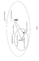
- FIG.1 shows a mobile communication system according to embodiments of the present invention.
- part of LTE coverage area 11 i.e. coverage area of a wideband communication system
- an entire WLAN coverage area 21 i.e. coverage area of a narrowband communication system. That is, part of LTE coverage area 11 overlaps entire WLAN coverage area 21.
- LTE base station 10 which covers coverage area 11, transmits a signal in this coverage area 11. This signal is received by LTE relay station 30 and mobile station 40.
- LTE relay station 30 covers identical coverage area 31 to coverage area 21, which WLAN host station 20 has, and relays, in coverage area 31, the signal received from LTE base station 10 to mobile station 40. That is, LTE relay station 30 relays a signal of LTE in WLAN coverage area 21 only. Therefore, mobile station 40 directly receives a signal transmitted by LTE base station 10 in coverage area 11, and receives a signal relayed by LTE relay station 30 in coverage area 31 (i.e. coverage area 21).
- LTE relay station 30 In an identical place to WLAN host station 20.
- LTE relay station 30 adds, to the relay signal, information to show that mobile station 40 receiving the relay signal from LTE relay station 30, is located in WLAN coverage area 21.
- LTE relay station 30 adds either a frequency offset, a time offset or a power offset, as the above information to the signal received from LTE base station 10, and transmits the signal with the offset to mobile station 40, located in coverage area 31 (that is, coverage area 21). This process of adding an offset is performed in a lower layer than layer 1.
- mobile station 40 can decide whether or not the mobile station 40 is located in WLAN coverage area 21 based on which one of the above offsets is added to a received signal. Consequently, mobile station 40 can enjoy a WLAN communication service when mobile station 40 is located in coverage area 21 within coverage area 11.
- LTE base station 10 transmits a signal having a center frequency f C .
- LTE relay station 30 When LTE relay station 30 receives the signal from LTE base station 10 and relays the signal to mobile station 40, LTE relay station 30 adds frequency offset ⁇ f to the signal from LTE base station 10, to shift the center frequency to f R .
- the magnitude of ⁇ f varies between RATs covering an identical coverage area to coverage area 31 of LTE relay station 30. For example, if coverage area 31 of LTE relay station 30 is identical to WLAN coverage area 21 as shown in FIG.1 , ⁇ f is 30 kHz as shown in FIG.3 . Further, for example, if coverage area 31 of LTE relay station 30 is identical to a WiMAX coverage area, ⁇ f is 60 kHz as shown in FIG.3 . Then, LTE relay station 30 relays the signal having center frequency f R to mobile station 40.
- Mobile station 40 decides in which RAT coverage area mobile station 40 is located based on whether or not frequency offset ⁇ f is added to the received signal.
- mobile station 40 detects that mobile station 40 is located in the WiMAX coverage area and can enjoy both WiMAX and LTE communication services.
- mobile station 40 located outside the above overlapping part in LTE coverage area 11, receives only the signal having center frequency f C and transmitted by LTE base station 10. Accordingly, mobile station 40, located outside the above overlapping part in LTE coverage area 11, cannot detect frequency offset ⁇ f having the ranges shown in FIG.4 . For example, when ⁇ f having the ranges shown in FIG.4 is not added to a received signal, mobile station 40 detects that mobile station 40 is not located in WLAN coverage area 21 or in the WiMAX coverage area and can enjoy LTE communication service only. That is, when frequency offset ⁇ f is not added to a received signal, mobile station 40 can decide that mobile station 40 is located outside the coverage area of a narrowband communication system.
- the maximum frequency error due to crystal error in the mobile station upon detecting a coverage area is estimated, for example, ⁇ 5ppm.
- the value of frequency offset ⁇ f added by LTE relay station 30 needs to be within the range of f detect that can be detected in mobile station 40 and separatable from the maximum frequency error f error_max ⁇ 14 kHz. That is, to make detection easier, it is preferable that the value of ⁇ f meets both condition (1) ⁇ f ⁇ f detect -f error_max and condition (2) ⁇ f>2*f error_max . Then, with the present embodiment, as shown in FIG.3 , ⁇ f in WLAN is 30 kHz and ⁇ f in WiMAX is 60 kHz.
- FIG.5 shows the configuration of LTE relay station 30 according to the present embodiment.
- radio receiving section 302 receives a signal transmitted from LTE base station 10 via antenna 301, and performs receiving processing including down-conversion and A/D conversion on the received signal, to output the resulting signal to frequency offset addition section 304.
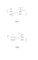
- Offset determination section 303 determines frequency offset ⁇ f with reference to the table shown in FIG.3 according to RAT type information received as input. If the RAT type is WLAN, ⁇ f is determined to be 30 kHz. Further, if the RAT type is WiMAX, ⁇ f is determined to be 60 kHz. If LTE relay station 30 is connected to a host station of a narrowband communication system that covers an identical coverage area to LTE relay station 30 (e.g. WLAN host station 20 in FIG.1 ) via a wired connection, LTE relay station 30 acquires RAT type information from the host station. ⁇ f determined in offset determination section 303 is inputted to frequency offset addition section 304.
- Frequency offset addition section 304 adds ⁇ f determined in offset determination section 303 to the signal received as input from radio receiving section 302, and outputs the signal with the frequency offset to radio transmitting section 305.
- Radio transmitting section 305 performs transmitting processing including D/A conversion and up-conversion on the signal with the frequency offset, and relays the resulting signal from antenna 301 to mobile station 40.
- FIG.6 shows the configuration of mobile station 40 according to the present embodiment.
- radio receiving section 402 receives only a signal from LTE base station 10, or a signal from LTE base station 10 and a signal from LTE relay station 30 via antenna 401, and performs receiving processing including down-conversion and A/D conversion on each received signal, to output the resulting signal to frequency error compensation section 403, frequency error detection section 404 and frequency offset detection section 405.
- Frequency error compensation section 403 compensates for the frequency error f error of the received signal and outputs the signal after the frequency error compensation to demodulation section 407 and frequency offset compensation section 408.
- Demodulation section 407 demodulates the signal after frequency error compensation and outputs the demodulated signal to diversity combination section 410.
- the detected ⁇ f is inputted to RAT detection section 406 and frequency offset compensation section 408.
- Frequency offset compensation section 408 further compensates for the frequency offset ⁇ f with the signal after frequency error compensation and outputs the signal after frequency offset compensation, to demodulation section 409.
- Demodulation section 409 demodulates the signal after the frequency error compensation and the frequency offset compensation, and outputs the demodulated signal to diversity combination section 410.
- Diversity combination section 410 diversity-combines the signal received as input from demodulation section 407 and the signal received as input from demodulation section 409 and outputs a combined signal.
- RAT detection section 406 which has the table shown in FIG.4 detects in which RAT coverage area mobile station 40 is located as described above, with reference to the table shown in FIG.4 according to ⁇ f detected by frequency offset detection section 405. Then, RAT detection section 406 outputs a RAT detection result.
- LTE relay station 30 receives a signal having a peak at time to from LTE base station 10.
- LTE relay station 30 When LTE relay station 30 receives the signal from LTE base station 10 and relays the signal to mobile station 40, LTE relay station 30 adds time offset ⁇ T to the signal from LTE base station 10, to generate a signal having a peak at time t 1 .
- the magnitude of ⁇ T varies between RATs covering an identical coverage area to coverage area 31 of LTE relay station 30. For example, ,if coverage area 31 of LTE relay station 30 is identical to WLAN coverage area 21 as shown in FIG.1 , ⁇ T is 5 samples as shown in FIG.8 . Further, for example, if coverage area 31 of LTE relay station 30 is identical to a WiMAX coverage area, ⁇ T is 10 samples as shown in FIG.8 . Then, LTE relay station 30 relays the signal having the time offset ⁇ T and the peak at time t 1 , to mobile station 40.
- Mobile station 40 decides in which RAT coverage area mobile station 40 is located based on whether or not time offset ⁇ T is added to the received signal.
- mobile station 40 detects that mobile station 40 is located in the WiMAX coverage area and can enjoy both WiMAX and LTE communication services.
- mobile station 40 located outside the above overlapping part in LTE coverage area 11, receives only the signal having a peak at time to and transmitted by LTE base station 10. Accordingly, mobile station 40, located outside the above overlapping part in LTE coverage area 11, cannot detect time offset ⁇ T having the ranges shown in FIG.9 . For example, when ⁇ T having the ranges shown in FIG.9 is not added to a received signal, mobile station 40 detects that mobile station 40 is not located in WLAN coverage area 21 or in the WiMAX coverage area and can enjoy LTE communication service only. That is, when time offset ⁇ T is not added to a received signal, mobile station 40 can decide that mobile station 40 is located outside the coverage area of a narrowband communication system.
- a guard interval T guard is set based on several tens to hundreds of samples, t aking into consideration of the maximum delay time of a multipath T delay_max . That is, to make detection easier, it is preferable that the value of time offset ⁇ T added by LTE relay station 30, meets the condition ⁇ T ⁇ T guard -T delay_may .
- FIG.10 shows the configuration of LTE relay station 30 according to the present embodiment. Further, in FIG.10 the same reference numerals are assigned to the same parts in FIG.5 (Embodiment 1), and description thereof will be omitted.
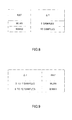
- offset determination section 306 which has the table shown in FIG.8 determines time offset ⁇ T with reference to the table shown in FIG.8 according to RAT type information received as input. If the RAT type is WLAN, ⁇ T is determined to be 5 samples. Further, if the RAT type is WiMAX, ⁇ T is determined to be 10 samples. If LTE relay station 30 is connected to a host station of a narrowband communication system that covers an identical coverage area to LTE relay station 30 (e.g. WLAN host station 20 in FIG.1 ) via a wired connection, LTE relay station 30 acquires RAT type information from the host station. ⁇ T determined in offset determination section 306 is inputted to time offset addition section 307.
- Time offset addition section 307 adds ⁇ T determined in offset determination section 306 to the signal received as input from radio receiving section 302, and outputs the signal with the time offset to radio transmitting section 305.
- FIG.11 shows the configuration of mobile station 40 according to the present embodiment. Further, in FIG.11 the same reference numerals are assigned to the same parts in FIG.6 (Embodiment 1), and description thereof will be omitted.
- radio receiving section 402 receives only a signal from LTE base station 10, or a signal from LTE base station 10 and a signal from LTE relay station 30 via antenna 401, and performs receiving processing including down-conversion and A/D conversion on each received signal, to output the resulting signal to time error compensation section 411, time error detection section 412 and time offset detection section 413.
- Time error detection section 412 detects time error of the received signal by the channel and outputs the detected time error to time error compensation section 411 and time offset detection section 413.
- Time error compensation section 411 compensates for the time error of the received signal by the channel and outputs the signal after the time error compensation, to demodulation section 415 and time offset compensation section 416.
- Demodulation section 415 demodulates the signal after time error compensation and outputs the demodulated signal to diversity combination section 410.
- the detected ⁇ T is inputted to RAT detection section 414 and time offset compensation section 416.
- Time offset compensation section 416 further compensates for the time offset ⁇ T with the signal after time error compensation and outputs the signal after time offset compensation, to demodulation section 417.
- Demodulation section 417 demodulates the signal after time error compensation and time offset compensation and outputs the demodulated signal to diversity combination section 410.
- Diversity combination section 410 diversity-combines the signal received as input from demodulation section 415 and the signal received as input from demodulation section 417 and outputs a combined signal.
- RAT detection section 414 which has the table shown in FIG.9 detects in which RAT coverage area mobile station 40 is located, as described above, with reference to the table shown in FIG.9 according to ⁇ T detected by time offset detection section 413. Then, RAT detection section 414 outputs a RAT detection result.
- LTE base station 10 transmits a signal having power P 0 .
- LTE relay station 30 When LTE relay station 30 receives a signal from LTE base station 10 and relays the signal to mobile station 40, LTE relay station 30 adds power offset ⁇ P to part of the signal from LTE base station 10, to generate a signal having power P 0 and P 1 .
- the magnitude of ⁇ P varies between RATs covering an identical coverage area to coverage area 31 of LTE relay station 30. For example, if coverage area 31 of LTE relay station 30 is identical to WLAN coverage area 21 as shown in FIG.1 , ⁇ P is -3dB as shown in FIG.13 . Further, for example, if coverage area 31 of LTE relay station 30 is identical to a WiMAX coverage area, ⁇ P is +5dB as shown in FIG.13 . Then, LTE relay station 30 relays the signal with power offset ⁇ P to mobile station 40.
- Mobile station 40 detects in which RAT coverage area mobile station 40 is located based on whether or not power offset ⁇ P is added to the received signal.
- mobile station 40 detects that mobile station 40 is located in the WiMAX coverage area and can enjoy both WiMAX and LTE communication services.
- mobile station 40 located outside the above overlapping part in LTE coverage area 11, receives only the signal having power P 0 and transmitted by LTE base station 10. Accordingly, mobile station 40, located outside the above overlapping part in LTE coverage area 11, cannot detect power offset ⁇ P having the ranges shown in FIG.14 . For example, when ⁇ P having the ranges shown in FIG.14 is not added to a received signal, mobile station 40 detects that mobile station 40 is not located in WLAN coverage area 21 or in the WiMAX coverage area and can enjoy LTE communication service only. That is, when power offset ⁇ P is not added to a received signal, mobile station 40 can decide that mobile station 40 is located outside the coverage area of a narrowband communication system.
- received dynamic range P total is usually set by adding a margin to dynamic range P fading estimated using fading fluctuations. That is, to make detection easier, it is preferable that the value of power offset ⁇ P is added by LTE relay station 30, meets the condition ⁇ P ⁇ P total -P fading .
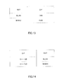
- FIG.15 shows the configuration of LTE relay station 30 according to the present embodiment. Further, in FIG.15 the same reference numerals are assigned to the same parts in FIG.5 (Embodiment 1), and description thereof will be omitted.
- offset determination section 308 which has the table shown in FIG.13 determines power offset ⁇ P with reference to the table shown in FIG.13 according to RAT type information received as input. If the RAT type is WLAN, ⁇ P is determined to be -3dB. Further, if the RAT type is WiMAX, ⁇ P is determined to be +5dB. If LTE relay station 30 is connected to a host station of a narrowband communication system that covers an identical coverage area to LTE relay station 30 (e.g. WLAN host station 20 in FIG.1 ) via a wired connection, LIE relay station 30 acquires RAT type information from the host station. ⁇ P determined in offset determination section 308 is inputted to power offset addition section 309.
- Power offset addition section 309 adds ⁇ P determined in offset determination section 308 to part of the signal received as input from radio receiving section 302, and outputs the signal with the power offset to radio transmitting section 305.
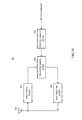
- FIG.16 shows the configuration of mobile station 40 according to the present embodiment. Further, in FIG.16 the same reference numerals are assigned to the same parts in FIG.6 (Embodiment 1), and description thereof will be omitted.
- radio receiving section 402 receives only a signal from LTE base station 10, or a signal from LTE base station 10 and a signal from LTE relay station 30 via antenna 401, and performs receiving processing including down-conversion and A/D conversion on each received signal, to output the resulting signal to power offset detection section 418, demodulation section 420 and power offset compensation section 421.
- Demodulation section 420 demodulates the received signal and outputs the demodulated signal to diversity combination section 410.
- the detected ⁇ P is inputted to RAT detection section 419 and power offset compensation section 421.
- Power offset compensation section 421 compensates for the power offset ⁇ P with the received signal and outputs the signal after power offset compensation, to demodulation section 422.
- Demodulation section 422 demodulates the signal after power offset compensation and outputs the demodulated signal to diversity combination section 410.
- Diversity combination section 410 diversity-combines the signal received as input from demodulation section 420 and the signal received as input from demodulation section 422 and outputs a combined signal.
- RAT detection section 419 which has the table shown in FIG.14 , and detects in which RAT coverage area mobile station 40 is located as described above, with reference to the table shown in FIG.14 according to the ⁇ P detected by power offset detection section 418. Then, RAT detection section 419 outputs a RAT detection result.
- Embodiments 1 to 3 of the present invention have been explained.
- the relay station of a wideband communication system including LTE covers an identical coverage area to a coverage area of a narrowband communication system including WLAN and WiMAX. Then, the relay station of a wideband communication system adds either a frequency offset, a time offset or a power offset as information showing that the mobile station, which receives a relay signal from the relay station, is located in the coverage area of a narrowband communication system, to a signal received from the base station of the wideband communication system, and relays the resulting signal. Therefore, according to Embodiments 1 to 3, in a mobile communication system where a plurality of RATs mix, it is possible make a control channel for reporting RAT information unnecessary and it is possible to prevent capacity of a control channel from becoming tight or insufficient.
- the mobile station can detect the coverage area of a narrowband communication system using a relay signal in a wideband communication system, and therefore, when the mobile station detects the coverage area of each RAT, the mobile station does not need to communicate using a control channel or narrowband communication system. That is, according to Embodiments 1 to 3, the mobile station can detect the coverage area of a narrowband communication system without switching to communication using a control channel or switching to communication using the narrowband communication system. Therefore, according to Embodiments 1 to 3, the mobile station can reduce power consumed by a process of detecting the coverage area of a narrowband communication system. Further, the mobile station can shorten the time it takes to detect the coverage area of a narrowband communication system.
- Embodiments 1 to 3 in the mobile station, it is possible to diversity-combine a signal received directly from the base station of a wideband communication system and a relay signal from the relay station of the wideband communication system, so that it is possible to provide diversity effect. Therefore, according to Embodiments 1 to 3, it is possible to improve reception performance of the mobile station.
- LTE base station 10 reports to mobile station 40 using a broadcast channel in advance what information mobile station 40, which has detected the coverage area of a narrowband communication system, needs to report to LTE base station 10.
- Information requested to report to LTE base station 10 when mobile station 40 detects the coverage area of a narrowband system include mobile station ID, RAT detection result and a communication status of mobile station 40.
- mobile station 40 When mobile station 40 detects the coverage area of a narrowband communication system using a relay signal in a wideband communication system, mobile station 40 reports information requested in advance from LTE base station 10, to LTE base station 10.
- LTE base station 10 performs handover of mobile station 40 to the narrowband communication system. Consequently, according to the present embodiment, LTE base station 10 can disperse traffic in the wideband communication system and the narrowband communication system, and optimally control the overall traffic in the coverage area of LTE base station 10.
- mobile station 40 it is not necessary to switch a carrier frequency or measure the power of a narrowband communication system until mobile station 40 receives a handover command to a narrowband communication system from LTE base station 10, so that it is possible to reduce the processing loads in mobile station 40.
- mobile station 40 it is possible to reduce the time it takes to detect the coverage area of a narrowband communication system, so that, according to the present embodiment, mobile station 40 can report information quickly to LTE base station 10, and consequently, following the traffic control in LTE base station 10 improves.
- the present invention may be implemented by combining the above embodiments.
- the present invention does not limit the RAT of a wideband communication system to LTE.
- other RATs of wideband communication systems include W-CDMA, LTE-Advanced or communication systems after LTE-Advanced.
- the present invention does not limit RATs of narrowband communication systems to WLAN and WiMAX.
- other RATs of narrowband communication systems include LTE, LTE-Advanced or communication systems after LTE-Advanced, which are used as hotspots.
- the present invention may be implemented as described above in cases where part of the coverage area of a wideband communication system includes part of the coverage area of a narrowband communication system and the part of the coverage area of the wideband communication system overlaps the part of the coverage area of the narrowband communication system.
- a base station apparatus may be referred to as a "Node B” and a mobile station apparatus may be referred to as a "UE.”
- the relay station according to the embodiments is referred to as “repeater,” “simple base station,” “cluster head,” and so on.
- Each function block employed in the description of each of the aforementioned embodiments may typically be implemented as an LSI constituted by an integrated circuit. These may be individual chips or partially or totally contained on a single chip. These may be individual chips or partially or totally contained on a single chip.
- LSI LSI
- IC integrated circuit
- system LSI system LSI
- super LSI ultra LSI
- ultra LSI ultra LSI
- the method of circuit integration is not limited to LSIs, and implementation using dedicated circuitry or general purpose processors is also possible.
- a programmable FPGA Field Programmable Gate Array
- reconfigurable processor where connections and settings of circuit cells within an LSI can be reconfigured is also possible.
- the present invention is applicable to, for example, communication systems (for example, multihop systems) in which radio communication apparatuses including mobile stations and base stations carry out radio communication via relay stations.
- communication systems for example, multihop systems
- radio communication apparatuses including mobile stations and base stations carry out radio communication via relay stations.
Abstract
Description
- The present invention relates to a relay station, mobile station and relay transmission method in mobile communication systems.
- In recent years, with the multimediatization of information in mobile communication systems, transmitting high capacity data such as still images and movies in addition to speech data has become popular. To realize the transmission of high capacity data, a technology in which a high-frequency radio band is used to provide a high transmission rate is studied actively.
- However, when a high-frequency radio band is used, although a high transmission rate can be expected in a short distance, attenuation due to transmission distance becomes greater as the distance increases. Accordingly, when the mobile communication system employing a high-frequency radio band is operated, the coverage area of a radio communication base station apparatus (hereinafter "base station") becomes small, which requires that a larger number of base stations be set up in order to prevent the service area from reducing. Since the set-up of base stations involves large costs, a technology is strongly demanded for realizing communication services which employ a high-frequency radio band and preventing an increase in the number of base stations.
- To meet this demand, to expand the coverage area of the base stations, relay transmission technologies are investigated in which a radio communication relay station apparatus (hereinafter "relay station") is set up between a radio communication mobile station apparatus (hereinafter "mobile station") and a base station, and in which communication between the mobile station and the base station is carried out via the relay station.
- Meanwhile, in future mobile communication systems, combining various radio access technologies (RATs) such as W-CDMA (Wideband Code Division Multiple Access), LTE (long-term evolution), WLAN (Wireless LAN), and WiMAX (Worldwide Interoperability for Microwave Access) and overlapping a plurality of RAT coverage areas in the service area of mobile communication will be taken into consideration. Then, in these mobile communication systems, a mobile station needs to detect in which RAT coverage area the mobile station is currently located and what communication service the mobile station is enjoyable. For example, when part of an LTE coverage area includes a WLAN coverage area, a mobile station located in the WLAN coverage area does not enjoy a WLAN communication service unless the mobile station detects that the mobile station is located in the WLAN coverage area, and the mobile station enjoys an LTE communication service only.
- Then, conventionally, Non-Patent Document 1 discloses a technique of detecting in which RAT coverage area the mobile stations are located by reporting another RAT's information (e.g. WLAN) to the mobile stations from a RAT's base station (e.g. LTE) based on location information of the mobile stations.
Non-Patent Document 1: 3GPP TS 25.331 V5.19.0 (2006-12); Technical Specification, 3rd Generation Partnership Project; Technical Specification Group Radio Access Network; Radio Resource Control (RRC); Protocol Specification (Release 5) - However, with the above conventional technique, a control channel for reporting information about other RATs to the mobile stations is necessary. For example, when part of an LTE coverage area includes a WLAN coverage area, according to the above conventional technique, an LTE base station needs to report to mobile stations RAT information about WLAN (i.e. the information including RAT types and coverage area information about WLAN) using an LTE control channel. For this reason, according to the above conventional technique, a control channel of large capacity is necessary to report RAT information. The number of mixed RATs is expected to further increase in the future, and therefore there is a fear that the amount of RAT information and the frequency of reporting RAT information increase become tight or insufficient control channel capacity.
- It is therefore an object of the present invention to provide a relay station, mobile station and relay transmission method that make a control channel for reporting RAT information unnecessary and prevent control channel capacity from becoming tight or insufficient in a mobile communication system in which a plurality of RATs mix.
- The relay station of the present invention adopts a configuration including: a receiving section that receives a signal from a base station employing a first radio access technique and covering a first coverage area; an addition section that adds one of a frequency offset, a time offset and a power offset to the signal; and a transmitting section that transmits to a mobile station the signal with the offset, in a third coverage area that is identical to a second coverage area, part or entirety of which includes the first coverage area, and which is covered by a host station employing a second radio access technique different from the first radio access technique.
- The mobile station of the present invention adopts a configuration including: a receiving section that receives, in a first coverage area, a signal transmitted by a base station employing a first radio access technique and covering a first coverage area, and that receives a signal relayed by a relay station in a third coverage area that is identical to a second coverage area, part or entirety of which includes the first coverage area, and which is covered by a host station employing a second radio access technique different from the first radio access technique; and a detection section that detects whether or not the mobile station is located in the second coverage area, based on which one of a frequency offset, a time offset and a power offset is added to the received signal.
- The relay transmission method of the present invention includes steps of: adding one of a frequency offset, a time offset and a power offset to a signal received from a base station, employing a first radio access technique and covering a first coverage area; and transmitting the signal with one offset to a mobile station in a third coverage area that is identical to a second coverage area, part or entirety of which includes the first coverage area, and which is covered by a host station employing a second radio access technique different from the first radio access technique.
- According to the present invention, in the mobile communication system in which a plurality of RATs mix, it is possible to make a control channel for reporting RAT information unnecessary and prevent control channel capacity from becoming tight or insufficient.
-
-
FIG.1 illustrates a configuration of the mobile communication system according to embodiments of the present invention; -
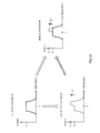
FIG.2 is an example of transmitting and receiving a signal according to Embodiment 1 of the present invention; -
FIG.3 is a reference table that the relay station has, according to Embodiment 1 of the present invention; -
FIG.4 is a reference table that the mobile station has, according to Embodiment 1 of the present invention; -
FIG.5 is a block diagram showing the configuration of the relay station according to Embodiment 1 of the present invention; -
FIG.6 is a block diagram showing the configuration of the mobile station according to Embodiment 1 of the present invention; -
FIG.7 is an example of transmitting and receiving a signal according to Embodiment 2 of the present invention; -
FIG.8 is a reference table that the relay station has, according to Embodiment 2 of the present invention; -
FIG.9 is a reference table that the mobile station has, according to Embodiment 2 of the present invention; -
FIG.10 is a block diagram showing the configuration of the relay station according to Embodiment 2 of the present invention; -
FIG.11 is a block diagram showing the configuration of the mobile station according to Embodiment 2 of the present invention; -
FIG.12 is an example of transmitting and receiving a signal according toEmbodiment 3 of the present invention; -
FIG.13 is a reference table that the relay station has, according toEmbodiment 3 of the present invention; -
FIG.14 is a reference table that the mobile station has, according to Embodiment 3 of the present invention; -
FIG.15 is a block diagram showing the configuration of the relay station according toEmbodiment 3 of the present invention; and -
FIG.16 is a block diagram showing a configuration of the mobile station according toEmbodiment 3 of the present invention. - Now, embodiments of the present invention will be described in detail with reference to the accompanying drawings.
-
FIG.1 shows a mobile communication system according to embodiments of the present invention. As shown inFIG.1 , with the mobile communication system according to the following embodiments, part of LTE coverage area 11 (i.e. coverage area of a wideband communication system) includes an entire WLAN coverage area 21 (i.e. coverage area of a narrowband communication system). That is, part ofLTE coverage area 11 overlaps entireWLAN coverage area 21. -
LTE base station 10, which coverscoverage area 11, transmits a signal in thiscoverage area 11. This signal is received byLTE relay station 30 andmobile station 40.LTE relay station 30 coversidentical coverage area 31 tocoverage area 21, which WLANhost station 20 has, and relays, incoverage area 31, the signal received fromLTE base station 10 tomobile station 40. That is,LTE relay station 30 relays a signal of LTE inWLAN coverage area 21 only. Therefore,mobile station 40 directly receives a signal transmitted byLTE base station 10 incoverage area 11, and receives a signal relayed byLTE relay station 30 in coverage area 31 (i.e. coverage area 21). - To make
coverage area 31 andcoverage area 21 identical, it is preferable to positionLTE relay station 30 in an identical place toWLAN host station 20. - Further,
LTE relay station 30 adds, to the relay signal, information to show thatmobile station 40 receiving the relay signal fromLTE relay station 30, is located inWLAN coverage area 21. To be more specific,LTE relay station 30 adds either a frequency offset, a time offset or a power offset, as the above information to the signal received fromLTE base station 10, and transmits the signal with the offset tomobile station 40, located in coverage area 31 (that is, coverage area 21). This process of adding an offset is performed in a lower layer than layer 1. - That is,
mobile station 40 can decide whether or not themobile station 40 is located inWLAN coverage area 21 based on which one of the above offsets is added to a received signal. Consequently,mobile station 40 can enjoy a WLAN communication service whenmobile station 40 is located incoverage area 21 withincoverage area 11. - With the present embodiment, a case will be described where a frequency offset is added to a signal subject to relay.
- With the present embodiment, as shown in
FIG.2 ,LTE base station 10 transmits a signal having a center frequency fC. - When
LTE relay station 30 receives the signal fromLTE base station 10 and relays the signal tomobile station 40,LTE relay station 30 adds frequency offset Δf to the signal fromLTE base station 10, to shift the center frequency to fR. The magnitude of Δf varies between RATs covering an identical coverage area tocoverage area 31 ofLTE relay station 30. For example, ifcoverage area 31 ofLTE relay station 30 is identical toWLAN coverage area 21 as shown inFIG.1 , Δf is 30 kHz as shown inFIG.3 . Further, for example, ifcoverage area 31 ofLTE relay station 30 is identical to a WiMAX coverage area, Δf is 60 kHz as shown inFIG.3 . Then,LTE relay station 30 relays the signal having center frequency fR tomobile station 40. -
Mobile station 40 decides in which RAT coverage areamobile station 40 is located based on whether or not frequency offset Δf is added to the received signal. -
Mobile station 40, located in the overlapping part ofLTE coverage area 11 and another RAT coverage area, receives both the signal having center frequency fC and transmitted byLTE base station 10 and the signal having center frequency fR and relayed byLTE relay station 30. Accordingly,mobile station 40, located in overlapping part ofLTE coverage area 11 and another RAT coverage area, can detect frequency offset Δf = |fR-fC| added byLTE relay station 30. For example, as shown inFIG.4 , when Δf having a range of 29 to 31 kHz is added to a received signal,mobile station 40 detects thatmobile station 40 is located inWLAN coverage area 21 and can enjoy both WLAN and LTE communication services. Further, for example, as shown inFIG.4 , when Δf having a range of 59 to 61 kHz is added to a received signal,mobile station 40 detects thatmobile station 40 is located in the WiMAX coverage area and can enjoy both WiMAX and LTE communication services. - On the other hand,
mobile station 40, located outside the above overlapping part inLTE coverage area 11, receives only the signal having center frequency fC and transmitted byLTE base station 10. Accordingly,mobile station 40, located outside the above overlapping part inLTE coverage area 11, cannot detect frequency offset Δf having the ranges shown inFIG.4 . For example, when Δf having the ranges shown inFIG.4 is not added to a received signal,mobile station 40 detects thatmobile station 40 is not located inWLAN coverage area 21 or in the WiMAX coverage area and can enjoy LTE communication service only. That is, when frequency offset Δf is not added to a received signal,mobile station 40 can decide thatmobile station 40 is located outside the coverage area of a narrowband communication system. - Next, an optimal value of frequency offset Δf will be explained.
- In LTE, when the maximum downlink carrier frequency is 2690 MHz and the maximum moving speed of a mobile station is 350 km/h, the maximum frequency error due to crystal error in the mobile station upon detecting a coverage area (i.e. upon acquiring initial synchronization) is estimated, for example, ±5ppm. This maximum frequency error refers to an error in the initial status of the crystal provided in the mobile station, that is, an error before performing synchronization acquisition. Accordingly, the maximum Doppler shift due to fading is 872 Hz and the maximum frequency error due to crystal error is 13450 Hz. Accordingly, the maximum frequency error ferror_max=(the maximum Doppler shift due to fading + the maximum frequency error due to crystal error) = 14322Hz ≈ 14 kHz. Therefore, the value of frequency offset Δf added by
LTE relay station 30 needs to be within the range of fdetect that can be detected inmobile station 40 and separatable from the maximum frequency error ferror_max ≈ 14 kHz. That is, to make detection easier, it is preferable that the value of Δf meets both condition (1) Δf≤fdetect-ferror_maxand condition (2) Δf>2*ferror_max. Then, with the present embodiment, as shown inFIG.3 , Δf in WLAN is 30 kHz and Δf in WiMAX is 60 kHz. - Next, the configuration of
LTE relay station 30 according to the present embodiment will be described.FIG.5 shows the configuration ofLTE relay station 30 according to the present embodiment. - In
LTE relay station 30 shown inFIG.5 ,radio receiving section 302 receives a signal transmitted fromLTE base station 10 viaantenna 301, and performs receiving processing including down-conversion and A/D conversion on the received signal, to output the resulting signal to frequency offsetaddition section 304. - Offset
determination section 303, which has the table shown inFIG.3 , determines frequency offset Δf with reference to the table shown inFIG.3 according to RAT type information received as input. If the RAT type is WLAN, Δf is determined to be 30 kHz. Further, if the RAT type is WiMAX, Δf is determined to be 60 kHz. IfLTE relay station 30 is connected to a host station of a narrowband communication system that covers an identical coverage area to LTE relay station 30 (e.g.WLAN host station 20 inFIG.1 ) via a wired connection,LTE relay station 30 acquires RAT type information from the host station. Δf determined in offsetdetermination section 303 is inputted to frequency offsetaddition section 304. - Frequency offset
addition section 304 adds Δf determined in offsetdetermination section 303 to the signal received as input fromradio receiving section 302, and outputs the signal with the frequency offset toradio transmitting section 305. -
Radio transmitting section 305 performs transmitting processing including D/A conversion and up-conversion on the signal with the frequency offset, and relays the resulting signal fromantenna 301 tomobile station 40. - Next, the configuration of
mobile station 40 according to the present embodiment will be described.FIG.6 shows the configuration ofmobile station 40 according to the present embodiment. - In
mobile station 40 shown inFIG.6 ,radio receiving section 402 receives only a signal fromLTE base station 10, or a signal fromLTE base station 10 and a signal fromLTE relay station 30 viaantenna 401, and performs receiving processing including down-conversion and A/D conversion on each received signal, to output the resulting signal to frequencyerror compensation section 403, frequencyerror detection section 404 and frequency offsetdetection section 405. - Frequency
error detection section 404 detects a frequency error ferror of the received signal = (Doppler shift due to fading + the frequency error due to crystal error) and outputs the detected frequency error to frequencyerror compensation section 403 and frequency offsetdetection section 405. - Frequency
error compensation section 403 compensates for the frequency error ferror of the received signal and outputs the signal after the frequency error compensation todemodulation section 407 and frequency offsetcompensation section 408. -
Demodulation section 407 demodulates the signal after frequency error compensation and outputs the demodulated signal todiversity combination section 410. - Frequency offset
detection section 405 detects frequency offset Δf = |fR-fC| with the received signal. The detected Δf is inputted toRAT detection section 406 and frequency offsetcompensation section 408. - Frequency offset
compensation section 408 further compensates for the frequency offset Δf with the signal after frequency error compensation and outputs the signal after frequency offset compensation, todemodulation section 409. -
Demodulation section 409 demodulates the signal after the frequency error compensation and the frequency offset compensation, and outputs the demodulated signal todiversity combination section 410. -
Diversity combination section 410 diversity-combines the signal received as input fromdemodulation section 407 and the signal received as input fromdemodulation section 409 and outputs a combined signal. -
RAT detection section 406, which has the table shown inFIG.4 detects in which RAT coverage areamobile station 40 is located as described above, with reference to the table shown inFIG.4 according to Δf detected by frequency offsetdetection section 405. Then,RAT detection section 406 outputs a RAT detection result. - With the present embodiment, a case will be described where a time offset is added to a signal subject to relay.
- With the present embodiment, as shown in
FIG.7 ,LTE relay station 30 receives a signal having a peak at time to fromLTE base station 10. - When
LTE relay station 30 receives the signal fromLTE base station 10 and relays the signal tomobile station 40,LTE relay station 30 adds time offset ΔT to the signal fromLTE base station 10, to generate a signal having a peak at time t1. The magnitude of ΔT varies between RATs covering an identical coverage area tocoverage area 31 ofLTE relay station 30. For example, ,ifcoverage area 31 ofLTE relay station 30 is identical toWLAN coverage area 21 as shown inFIG.1 , ΔT is 5 samples as shown inFIG.8 . Further, for example, ifcoverage area 31 ofLTE relay station 30 is identical to a WiMAX coverage area, ΔT is 10 samples as shown inFIG.8 . Then,LTE relay station 30 relays the signal having the time offset ΔT and the peak at time t1, tomobile station 40. -
Mobile station 40 decides in which RAT coverage areamobile station 40 is located based on whether or not time offset ΔT is added to the received signal. -
Mobile station 40, which is located in overlapping part ofLTE coverage area 11 and another RAT coverage area, receives both the signal having a peak at time to and transmitted byLTE base station 10 and the signal having a peak at time t1 and relayed byLTE relay station 30. Accordingly,mobile station 40, which is located in overlapping part ofLTE coverage area 11 and another RAT coverage area, can detect time offset ΔT=|t1-t0| added byLTE relay station 30. For example, as shown inFIG.9 , when ΔT having a range of 3 to 7 samples is added to a received signal,mobile station 40 detects thatmobile station 40 is located inWLAN coverage area 21 and can enjoy both WLAN and LTE communication services. Further, for example, as shown inFIG.9 , when ΔT having a range of 8 to 12 samples is added to a received signal,mobile station 40 detects thatmobile station 40 is located in the WiMAX coverage area and can enjoy both WiMAX and LTE communication services. - On the other hand,
mobile station 40, located outside the above overlapping part inLTE coverage area 11, receives only the signal having a peak at time to and transmitted byLTE base station 10. Accordingly,mobile station 40, located outside the above overlapping part inLTE coverage area 11, cannot detect time offset ΔT having the ranges shown inFIG.9 . For example, when ΔT having the ranges shown inFIG.9 is not added to a received signal,mobile station 40 detects thatmobile station 40 is not located inWLAN coverage area 21 or in the WiMAX coverage area and can enjoy LTE communication service only. That is, when time offset ΔT is not added to a received signal,mobile station 40 can decide thatmobile station 40 is located outside the coverage area of a narrowband communication system. - In LTE, usually, a guard interval Tguard is set based on several tens to hundreds of samples, t aking into consideration of the maximum delay time of a multipath Tdelay_max. That is, to make detection easier, it is preferable that the value of time offset ΔT added by
LTE relay station 30, meets the condition ΔT≤ Tguard-Tdelay_may. - Next, the configuration of
LTE relay station 30 according to the present embodiment will be described.FIG.10 shows the configuration ofLTE relay station 30 according to the present embodiment. Further, inFIG.10 the same reference numerals are assigned to the same parts inFIG.5 (Embodiment 1), and description thereof will be omitted. - In
LTE relay station 30 shown inFIG.10 , offsetdetermination section 306, which has the table shown inFIG.8 determines time offset ΔT with reference to the table shown inFIG.8 according to RAT type information received as input. If the RAT type is WLAN, ΔT is determined to be 5 samples. Further, if the RAT type is WiMAX, ΔT is determined to be 10 samples. IfLTE relay station 30 is connected to a host station of a narrowband communication system that covers an identical coverage area to LTE relay station 30 (e.g.WLAN host station 20 inFIG.1 ) via a wired connection,LTE relay station 30 acquires RAT type information from the host station. ΔT determined in offsetdetermination section 306 is inputted to time offsetaddition section 307. - Time offset
addition section 307 adds ΔT determined in offsetdetermination section 306 to the signal received as input fromradio receiving section 302, and outputs the signal with the time offset toradio transmitting section 305. - Next, the configuration of
mobile station 40 according to the present embodiment will be described.FIG.11 shows the configuration ofmobile station 40 according to the present embodiment. Further, inFIG.11 the same reference numerals are assigned to the same parts inFIG.6 (Embodiment 1), and description thereof will be omitted. - In
mobile station 40 shown inFIG.11 ,radio receiving section 402 receives only a signal fromLTE base station 10, or a signal fromLTE base station 10 and a signal fromLTE relay station 30 viaantenna 401, and performs receiving processing including down-conversion and A/D conversion on each received signal, to output the resulting signal to timeerror compensation section 411, timeerror detection section 412 and time offsetdetection section 413. - Time
error detection section 412 detects time error of the received signal by the channel and outputs the detected time error to timeerror compensation section 411 and time offsetdetection section 413. - Time
error compensation section 411 compensates for the time error of the received signal by the channel and outputs the signal after the time error compensation, todemodulation section 415 and time offsetcompensation section 416. -
Demodulation section 415 demodulates the signal after time error compensation and outputs the demodulated signal todiversity combination section 410. - Time offset
detection section 413 detects time offset ΔT=|t1-t0| with the received signal. The detected ΔT is inputted toRAT detection section 414 and time offsetcompensation section 416. - Time offset
compensation section 416 further compensates for the time offset ΔT with the signal after time error compensation and outputs the signal after time offset compensation, todemodulation section 417. -
Demodulation section 417 demodulates the signal after time error compensation and time offset compensation and outputs the demodulated signal todiversity combination section 410. -
Diversity combination section 410 diversity-combines the signal received as input fromdemodulation section 415 and the signal received as input fromdemodulation section 417 and outputs a combined signal. -
RAT detection section 414, which has the table shown inFIG.9 detects in which RAT coverage areamobile station 40 is located, as described above, with reference to the table shown inFIG.9 according to ΔT detected by time offsetdetection section 413. Then,RAT detection section 414 outputs a RAT detection result. - With the present embodiment, cases will be described where a power offset is added to a signal subject to relay.
- With the present embodiment, as shown in
FIG.12 ,LTE base station 10 transmits a signal having power P0. - When
LTE relay station 30 receives a signal fromLTE base station 10 and relays the signal tomobile station 40,LTE relay station 30 adds power offset ΔP to part of the signal fromLTE base station 10, to generate a signal having power P0 and P1. The magnitude of ΔP varies between RATs covering an identical coverage area tocoverage area 31 ofLTE relay station 30. For example, ifcoverage area 31 ofLTE relay station 30 is identical toWLAN coverage area 21 as shown inFIG.1 , ΔP is -3dB as shown inFIG.13 . Further, for example, ifcoverage area 31 ofLTE relay station 30 is identical to a WiMAX coverage area, ΔP is +5dB as shown inFIG.13 . Then,LTE relay station 30 relays the signal with power offset ΔP tomobile station 40. -
Mobile station 40 detects in which RAT coverage areamobile station 40 is located based on whether or not power offset ΔP is added to the received signal. -
Mobile station 40, located in the overlapping part ofLTE coverage area 11 and another RAT coverage area, receives both the signal having power P0 and transmitted byLTE base station 10 and the signal having power P0 and P1 and relayed byLTE relay station 30. Accordingly,mobile station 40, located in overlapping part ofLTE coverage area 11 and another RAT coverage area, can detect power offset ΔP=|P1-P0| added byLTE relay station 30. For example, as shown inFIG.14 , when ΔP having a range of -5 to -1 dB is added to a received signal,mobile station 40 detects thatmobile station 40 is located inWLAN coverage area 21 and can enjoy both WLAN and LTE communication services. Further, for example, as shown inFIG.14 , when ΔP having a range of +3 to +7 dB is added to a received signal,mobile station 40 detects thatmobile station 40 is located in the WiMAX coverage area and can enjoy both WiMAX and LTE communication services. - On the other hand,
mobile station 40, located outside the above overlapping part inLTE coverage area 11, receives only the signal having power P0 and transmitted byLTE base station 10. Accordingly,mobile station 40, located outside the above overlapping part inLTE coverage area 11, cannot detect power offset ΔP having the ranges shown inFIG.14 . For example, when ΔP having the ranges shown inFIG.14 is not added to a received signal,mobile station 40 detects thatmobile station 40 is not located inWLAN coverage area 21 or in the WiMAX coverage area and can enjoy LTE communication service only. That is, when power offset ΔP is not added to a received signal,mobile station 40 can decide thatmobile station 40 is located outside the coverage area of a narrowband communication system. - In LTE, received dynamic range Ptotal is usually set by adding a margin to dynamic range Pfading estimated using fading fluctuations. That is, to make detection easier, it is preferable that the value of power offset ΔP is added by
LTE relay station 30, meets the condition ΔP≤Ptotal-Pfading. - Next, the configuration of
LTE relay station 30 according to the present embodiment will be described.FIG.15 shows the configuration ofLTE relay station 30 according to the present embodiment. Further, inFIG.15 the same reference numerals are assigned to the same parts inFIG.5 (Embodiment 1), and description thereof will be omitted. - In
LTE relay station 30 shown inFIG.15 , offsetdetermination section 308, which has the table shown inFIG.13 determines power offset ΔP with reference to the table shown inFIG.13 according to RAT type information received as input. If the RAT type is WLAN, ΔP is determined to be -3dB. Further, if the RAT type is WiMAX, ΔP is determined to be +5dB. IfLTE relay station 30 is connected to a host station of a narrowband communication system that covers an identical coverage area to LTE relay station 30 (e.g.WLAN host station 20 inFIG.1 ) via a wired connection,LIE relay station 30 acquires RAT type information from the host station. ΔP determined in offsetdetermination section 308 is inputted to power offsetaddition section 309. - Power offset
addition section 309 adds ΔP determined in offsetdetermination section 308 to part of the signal received as input fromradio receiving section 302, and outputs the signal with the power offset toradio transmitting section 305. - Next, the configuration of
mobile station 40 according to the present embodiment will be described.FIG.16 shows the configuration ofmobile station 40 according to the present embodiment. Further, inFIG.16 the same reference numerals are assigned to the same parts inFIG.6 (Embodiment 1), and description thereof will be omitted. - In
mobile station 40 shown inFIG.16 ,radio receiving section 402 receives only a signal fromLTE base station 10, or a signal fromLTE base station 10 and a signal fromLTE relay station 30 viaantenna 401, and performs receiving processing including down-conversion and A/D conversion on each received signal, to output the resulting signal to power offsetdetection section 418,demodulation section 420 and power offsetcompensation section 421. -
Demodulation section 420 demodulates the received signal and outputs the demodulated signal todiversity combination section 410. - Power offset
detection section 418 detects power offset ΔP=|P1-P0| with the received signal. The detected ΔP is inputted toRAT detection section 419 and power offsetcompensation section 421. - Power offset
compensation section 421 compensates for the power offset ΔP with the received signal and outputs the signal after power offset compensation, todemodulation section 422. -
Demodulation section 422 demodulates the signal after power offset compensation and outputs the demodulated signal todiversity combination section 410. -
Diversity combination section 410 diversity-combines the signal received as input fromdemodulation section 420 and the signal received as input fromdemodulation section 422 and outputs a combined signal. -
RAT detection section 419, which has the table shown inFIG.14 , and detects in which RAT coverage areamobile station 40 is located as described above, with reference to the table shown inFIG.14 according to the ΔP detected by power offsetdetection section 418. Then,RAT detection section 419 outputs a RAT detection result. - Embodiments 1 to 3 of the present invention have been explained.
- In this way, according to Embodiments 1 to 3, the relay station of a wideband communication system including LTE covers an identical coverage area to a coverage area of a narrowband communication system including WLAN and WiMAX. Then, the relay station of a wideband communication system adds either a frequency offset, a time offset or a power offset as information showing that the mobile station, which receives a relay signal from the relay station, is located in the coverage area of a narrowband communication system, to a signal received from the base station of the wideband communication system, and relays the resulting signal. Therefore, according to Embodiments 1 to 3, in a mobile communication system where a plurality of RATs mix, it is possible make a control channel for reporting RAT information unnecessary and it is possible to prevent capacity of a control channel from becoming tight or insufficient.
- Further, according to Embodiments 1 to 3, the mobile station can detect the coverage area of a narrowband communication system using a relay signal in a wideband communication system, and therefore, when the mobile station detects the coverage area of each RAT, the mobile station does not need to communicate using a control channel or narrowband communication system. That is, according to Embodiments 1 to 3, the mobile station can detect the coverage area of a narrowband communication system without switching to communication using a control channel or switching to communication using the narrowband communication system. Therefore, according to Embodiments 1 to 3, the mobile station can reduce power consumed by a process of detecting the coverage area of a narrowband communication system. Further, the mobile station can shorten the time it takes to detect the coverage area of a narrowband communication system.
- Further, according to Embodiments 1 to 3, in the mobile station, it is possible to diversity-combine a signal received directly from the base station of a wideband communication system and a relay signal from the relay station of the wideband communication system, so that it is possible to provide diversity effect. Therefore, according to Embodiments 1 to 3, it is possible to improve reception performance of the mobile station.
- In the above Embodiments 1 to 3,
LTE base station 10 reports tomobile station 40 using a broadcast channel in advance what informationmobile station 40, which has detected the coverage area of a narrowband communication system, needs to report toLTE base station 10. Information requested to report toLTE base station 10 whenmobile station 40 detects the coverage area of a narrowband system include mobile station ID, RAT detection result and a communication status ofmobile station 40. - When
mobile station 40 detects the coverage area of a narrowband communication system using a relay signal in a wideband communication system,mobile station 40 reports information requested in advance fromLTE base station 10, toLTE base station 10. - By this means, necessary information is sequentially reported to
LTE base station 10 frommobile station 40 located in the coverage area of a narrowband communication system, so that it is possible to control traffic using not only coverage area information of a wideband communication system but also coverage area information of a narrowband communication system. For example, whenmobile station 40 communicating in a wideband communication system with heavy traffic is located in the coverage area of a narrowband communication system with low traffic,LTE base station 10 performs handover ofmobile station 40 to the narrowband communication system. Consequently, according to the present embodiment,LTE base station 10 can disperse traffic in the wideband communication system and the narrowband communication system, and optimally control the overall traffic in the coverage area ofLTE base station 10. Further, inmobile station 40, it is not necessary to switch a carrier frequency or measure the power of a narrowband communication system untilmobile station 40 receives a handover command to a narrowband communication system fromLTE base station 10, so that it is possible to reduce the processing loads inmobile station 40. - Further, as described above, according to Embodiments 1 to 3, in
mobile station 40, it is possible to reduce the time it takes to detect the coverage area of a narrowband communication system, so that, according to the present embodiment,mobile station 40 can report information quickly toLTE base station 10, and consequently, following the traffic control inLTE base station 10 improves. - Embodiments of the present invention have been explained.
- The present invention may be implemented by combining the above embodiments.
- Further, although cases have been explained above with the embodiments where one example of RATs of wideband communication systems is LTE and one example of RATs of narrowband communication systems is WLAN and WiMAX, the present invention does not limit the RAT of a wideband communication system to LTE. For example, other RATs of wideband communication systems include W-CDMA, LTE-Advanced or communication systems after LTE-Advanced. Further, the present invention does not limit RATs of narrowband communication systems to WLAN and WiMAX. For example, other RATs of narrowband communication systems include LTE, LTE-Advanced or communication systems after LTE-Advanced, which are used as hotspots.
- Further, although cases have been explained with the above embodiments where part of the coverage area of a wideband communication system includes the entire coverage area of a narrowband communication system and the part of the coverage area of the wideband communication system overlaps the entire coverage area of the narrowband communication system, the present invention may be implemented as described above in cases where part of the coverage area of a wideband communication system includes part of the coverage area of a narrowband communication system and the part of the coverage area of the wideband communication system overlaps the part of the coverage area of the narrowband communication system.
- Further, a base station apparatus may be referred to as a "Node B" and a mobile station apparatus may be referred to as a "UE." Furthermore, the relay station according to the embodiments is referred to as "repeater," "simple base station," "cluster head," and so on.
- Further, although cases have been described with the above embodiment as examples where the present invention is configured by hardware, the present invention can also be realized by software.
- Each function block employed in the description of each of the aforementioned embodiments may typically be implemented as an LSI constituted by an integrated circuit. These may be individual chips or partially or totally contained on a single chip. These may be individual chips or partially or totally contained on a single chip.
- "LSI" is adopted here but this may also be referred to as "IC," "system LSI," "super LSI," or "ultra LSI" depending on differing extents of integration. Further, the method of circuit integration is not limited to LSIs, and implementation using dedicated circuitry or general purpose processors is also possible. After LSI manufacture, utilization of a programmable FPGA (Field Programmable Gate Array) or a reconfigurable processor where connections and settings of circuit cells within an LSI can be reconfigured is also possible.
- Further, if integrated circuit technology comes out to replace LSI's as a result of the advancement of semiconductor technology or a derivative other technology, it is naturally also possible to carry out function block integration using this technology. Application of biotechnology is also possible.
- The disclosures of Japanese Patent Application No.
2007-188572, filed on July 19, 2007 2007-330837, filed on December 21, 2007 - The present invention is applicable to, for example, communication systems (for example, multihop systems) in which radio communication apparatuses including mobile stations and base stations carry out radio communication via relay stations.
Claims (4)
- A relay station comprising:a receiving section that receives a signal from a base station employing a first radio access technique and covering a first coverage area;an addition section that adds one of a frequency offset, a time offset and a power offset to the signal; anda transmitting section that transmits to a mobile station the signal with the offset, in a third coverage area that is identical to a second coverage area, part or entirety of which includes the first coverage area, and which is covered by a host station employing a second radio access technique different from the first radio access technique.
- A mobile station comprising:a receiving section that receives, in a first coverage area, a signal transmitted by a base station employing a first radio access technique and covering the first coverage area, and that receives a signal relayed by a relay station in a third coverage area that is identical to a second coverage area, part or entirety of which includes the first coverage area, and which is covered by a host station employing a second radio access technique different from the first radio access technique; anda detection section that detects whether or not the mobile station is located in the second coverage area, based on which one of a frequency offset, a time offset and a power offset is added to the received signal.
- A mobile communication system comprising:a base station that employs a first radio access technique and covers a first coverage area;a host station that covers a second coverage area, part or entirety of which includes the first coverage area, and that employs a second access technique different from the first radio access technique;a relay station that covers a third coverage area identical to the second coverage area, and that adds one of a frequency offset, a time offset and a power offset to the signal received from the base station, and that transmits the signal with the offset to a mobile station located in the third coverage area; anda mobile station that detects whether or not the mobile station is located in the second coverage area, based on whether or not the offset is added to the received signal.
- A relay transmission method comprising the steps of:adding one of a frequency offset, a time offset and a power offset to a signal received from a base station, employing a first radio access technique and covering a first coverage area; andtransmitting the signal with one offset to a mobile station in a third coverage area that is identical to a second coverage area, part or entirety of which includes the first coverage area, and which is covered by a host station employing a second radio access technique different from the first radio access technique.
Applications Claiming Priority (3)
| Application Number | Priority Date | Filing Date | Title |
|---|---|---|---|
| JP2007188572 | 2007-07-19 | ||
| JP2007330837 | 2007-12-21 | ||
| PCT/JP2008/001935 WO2009011135A1 (en) | 2007-07-19 | 2008-07-18 | Relay station, mobile station, and relay transmission method in mobile communication system |
Publications (3)
| Publication Number | Publication Date |
|---|---|
| EP2173117A1 true EP2173117A1 (en) | 2010-04-07 |
| EP2173117A4 EP2173117A4 (en) | 2014-07-02 |
| EP2173117B1 EP2173117B1 (en) | 2018-03-07 |
Family
ID=40259481
Family Applications (1)
| Application Number | Title | Priority Date | Filing Date |
|---|---|---|---|
| EP08790237.5A Active EP2173117B1 (en) | 2007-07-19 | 2008-07-18 | Relay station, mobile station, and relay transmission method in mobile communication system |
Country Status (5)
| Country | Link |
|---|---|
| US (2) | US8265551B2 (en) |
| EP (1) | EP2173117B1 (en) |
| JP (1) | JP5002650B2 (en) |
| RU (1) | RU2010101413A (en) |
| WO (1) | WO2009011135A1 (en) |
Cited By (4)
| Publication number | Priority date | Publication date | Assignee | Title |
|---|---|---|---|---|
| WO2013103754A1 (en) * | 2012-01-06 | 2013-07-11 | Qualcomm Incorporated | Long term evoluton (lte) user equipment relays having a licensed wireless or wired backhaul link and an unlicensed access link |
| TWI461015B (en) * | 2011-11-02 | 2014-11-11 | Sharp Kk | Communication system, mobile station device, base station device, communication method and integrated circuit |
| US9247479B2 (en) | 2010-09-02 | 2016-01-26 | Intel Deutschland Gmbh | Resource allocation in a mobile communication system |
| WO2017121406A1 (en) * | 2016-01-15 | 2017-07-20 | 中兴通讯股份有限公司 | Method and device for cooperative set establishment |
Families Citing this family (18)
| Publication number | Priority date | Publication date | Assignee | Title |
|---|---|---|---|---|
| JP5342294B2 (en) * | 2009-03-26 | 2013-11-13 | 京セラ株式会社 | Radio relay station and radio relay method |
| WO2010124447A1 (en) * | 2009-04-27 | 2010-11-04 | 华为技术有限公司 | Method and device for managing interference of relay |
| TW201114293A (en) | 2009-08-21 | 2011-04-16 | Interdigital Patent Holdings | Method and apparatus for a multi-radio access technology layer for splitting downlink-uplink over different radio access technologies |
| US9055535B2 (en) | 2010-04-30 | 2015-06-09 | Panasonic Intellectual Property Corporation Of America | Wireless communication device and method for controlling transmission power |
| DE102010036948B4 (en) | 2010-08-11 | 2016-02-25 | Intel Deutschland Gmbh | communication system |
| KR101857658B1 (en) | 2010-09-15 | 2018-05-14 | 엘지전자 주식회사 | Apparatus for transmitting control information in a wireless communication system and method thereof |
| WO2012036478A2 (en) * | 2010-09-15 | 2012-03-22 | Lg Electronics Inc. | Apparatus for transmitting control information in a wireless communication system and method thereof |
| JP5473860B2 (en) * | 2010-10-27 | 2014-04-16 | 株式会社日立製作所 | Mobile communication system and radio base station power saving control method |
| JP5890622B2 (en) | 2011-06-28 | 2016-03-22 | シャープ株式会社 | Mobile station, CSG type base station, wireless communication system, program, integrated circuit, and base station |
| WO2013013289A1 (en) | 2011-07-26 | 2013-01-31 | Research In Motion Limited | Smart relay network |
| WO2013013288A1 (en) * | 2011-07-26 | 2013-01-31 | Research In Motion Limited | Mobile device for a smart relay network |
| US20130244666A1 (en) * | 2012-03-19 | 2013-09-19 | Broadcom Corporation | Power Savings in a Mobile Communications Device Through Dynamic Control of Processed Bandwidth |
| US9247406B2 (en) * | 2012-11-29 | 2016-01-26 | Broadcom Corporation | Synchronous SOS messaging in a cellular network |
| CN104349330A (en) * | 2013-08-05 | 2015-02-11 | 中兴通讯股份有限公司 | Method, system and equipment for assisting multi-mode terminal in finding communication chance |
| US9756462B2 (en) * | 2014-09-09 | 2017-09-05 | Verizon Patent And Licensing Inc. | Device state derivation |
| US10091660B2 (en) * | 2015-08-12 | 2018-10-02 | W5 Technologies, Inc. | LTE preemption |
| CN113179504B (en) * | 2021-04-26 | 2023-03-31 | 中国电子科技集团公司第三十六研究所 | Communication network congestion control method and device and electronic equipment |
| US20230199573A1 (en) * | 2021-12-20 | 2023-06-22 | Motorola Solutions, Inc. | Device, system, and method for switching between a narrowband network and a broadband network |
Citations (4)
| Publication number | Priority date | Publication date | Assignee | Title |
|---|---|---|---|---|
| GB2272599A (en) * | 1992-11-12 | 1994-05-18 | Nokia Telecommunications Oy | A method of cellular radio communication and a cellular radio system for use in such method |
| US20030220075A1 (en) * | 2002-01-09 | 2003-11-27 | Baker Kenneth R. | Method and system for identifying and monitoring repeater traffic in a code division multiple access system |
| US20050130672A1 (en) * | 2001-10-25 | 2005-06-16 | Dean Richard F. | Method and system for determining mobile station position |
| US20050282491A1 (en) * | 2004-06-03 | 2005-12-22 | Gainey Kenneth M | Frequency translating repeater with low cost high performance local oscillator architecture |
Family Cites Families (14)
| Publication number | Priority date | Publication date | Assignee | Title |
|---|---|---|---|---|
| JP2778794B2 (en) | 1990-03-30 | 1998-07-23 | 日本電信電話株式会社 | Mobile propagation delay reduction method |
| FI105639B (en) * | 1997-06-25 | 2000-09-15 | Nokia Mobile Phones Ltd | An improved method for cell switching |
| KR100363216B1 (en) | 1999-10-29 | 2002-12-05 | 에스케이 텔레콤주식회사 | Multi-path repeating method for wireless communiction system and apparatus thereof |
| US6725058B2 (en) * | 2001-12-26 | 2004-04-20 | Nokia Corporation | Intersystem handover |
| JP3924499B2 (en) * | 2002-05-22 | 2007-06-06 | 株式会社エヌ・ティ・ティ・ドコモ | Composite wireless communication system and composite wireless communication method |
| JP3796200B2 (en) | 2002-06-20 | 2006-07-12 | インターナショナル・ビジネス・マシーンズ・コーポレーション | Wireless communication system and switching method |
| JP2005101820A (en) * | 2003-09-24 | 2005-04-14 | Matsushita Electric Ind Co Ltd | Communication terminal device and method for selecting communication system |
| JP4394474B2 (en) | 2004-02-16 | 2010-01-06 | 株式会社エヌ・ティ・ティ・ドコモ | Wireless relay system, wireless relay device, and wireless relay method |
| US7924785B2 (en) * | 2004-03-12 | 2011-04-12 | Interdigital Technology Corporation | Method and system for switching a radio access technology between wireless communication systems with a multi-mode wireless transmit/receive unit |
| CN100530964C (en) * | 2004-12-30 | 2009-08-19 | 鸿富锦精密工业(深圳)有限公司 | Signal generation circuit |
| GB2422067B (en) * | 2005-01-06 | 2007-09-05 | Toshiba Res Europ Ltd | Distributed network discovery |
| US20060217147A1 (en) * | 2005-01-18 | 2006-09-28 | Interdigital Technology Corporation | Method and system for system discovery and user selection |
| KR100975698B1 (en) * | 2005-06-13 | 2010-08-12 | 삼성전자주식회사 | Relay system and method for cellular communication |
| US8059582B2 (en) * | 2006-12-29 | 2011-11-15 | Nokia Corporation | Pico cell system access using cellular communications network |
-
2008
- 2008-07-18 US US12/669,148 patent/US8265551B2/en active Active
- 2008-07-18 JP JP2009523548A patent/JP5002650B2/en not_active Expired - Fee Related
- 2008-07-18 WO PCT/JP2008/001935 patent/WO2009011135A1/en active Application Filing
- 2008-07-18 RU RU2010101413/09A patent/RU2010101413A/en not_active Application Discontinuation
- 2008-07-18 EP EP08790237.5A patent/EP2173117B1/en active Active
-
2012
- 2012-08-14 US US13/585,621 patent/US8467723B2/en active Active
Patent Citations (4)
| Publication number | Priority date | Publication date | Assignee | Title |
|---|---|---|---|---|
| GB2272599A (en) * | 1992-11-12 | 1994-05-18 | Nokia Telecommunications Oy | A method of cellular radio communication and a cellular radio system for use in such method |
| US20050130672A1 (en) * | 2001-10-25 | 2005-06-16 | Dean Richard F. | Method and system for determining mobile station position |
| US20030220075A1 (en) * | 2002-01-09 | 2003-11-27 | Baker Kenneth R. | Method and system for identifying and monitoring repeater traffic in a code division multiple access system |
| US20050282491A1 (en) * | 2004-06-03 | 2005-12-22 | Gainey Kenneth M | Frequency translating repeater with low cost high performance local oscillator architecture |
Non-Patent Citations (1)
| Title |
|---|
| See also references of WO2009011135A1 * |
Cited By (10)
| Publication number | Priority date | Publication date | Assignee | Title |
|---|---|---|---|---|
| US9247479B2 (en) | 2010-09-02 | 2016-01-26 | Intel Deutschland Gmbh | Resource allocation in a mobile communication system |
| US9980200B2 (en) | 2010-09-02 | 2018-05-22 | Intel Deutschland Gmbh | Resource allocation in a mobile communication system |
| TWI461015B (en) * | 2011-11-02 | 2014-11-11 | Sharp Kk | Communication system, mobile station device, base station device, communication method and integrated circuit |
| WO2013103754A1 (en) * | 2012-01-06 | 2013-07-11 | Qualcomm Incorporated | Long term evoluton (lte) user equipment relays having a licensed wireless or wired backhaul link and an unlicensed access link |
| CN104041174A (en) * | 2012-01-06 | 2014-09-10 | 高通股份有限公司 | Long Term Evoluton (lte) User Equipment Relays Having A Licensed Wireless Or Wired Backhaul Link And An Unlicensed Access Link |
| KR20140113987A (en) * | 2012-01-06 | 2014-09-25 | 퀄컴 인코포레이티드 | Long term evolution (lte) user equipment relays having a licensed wireless or wired backhaul link and an unlicensed access link |
| CN104041174B (en) * | 2012-01-06 | 2018-08-31 | 高通股份有限公司 | With licensed wirelessly or non-wirelessly backhaul link and without approval long term evolution (LTE) user equipment repeater of access link |
| US10588101B2 (en) | 2012-01-06 | 2020-03-10 | Qualcomm Incorporated | Long term evoluton (LTE) user equipment relays having a licensed wireless or wired backhaul link and an unlicensed access link |
| WO2017121406A1 (en) * | 2016-01-15 | 2017-07-20 | 中兴通讯股份有限公司 | Method and device for cooperative set establishment |
| CN106982083A (en) * | 2016-01-15 | 2017-07-25 | 中兴通讯股份有限公司 | The method and apparatus that a kind of collaboration set is set up |
Also Published As
| Publication number | Publication date |
|---|---|
| US20120309390A1 (en) | 2012-12-06 |
| JPWO2009011135A1 (en) | 2010-09-16 |
| EP2173117A4 (en) | 2014-07-02 |
| US8467723B2 (en) | 2013-06-18 |
| WO2009011135A1 (en) | 2009-01-22 |
| EP2173117B1 (en) | 2018-03-07 |
| US20100197223A1 (en) | 2010-08-05 |
| US8265551B2 (en) | 2012-09-11 |
| RU2010101413A (en) | 2011-07-27 |
| JP5002650B2 (en) | 2012-08-15 |
Similar Documents
| Publication | Publication Date | Title |
|---|---|---|
| US8265551B2 (en) | Relay station, mobile station, and relay transmission method in mobile communication system | |
| US9191098B2 (en) | Capability reporting for relay nodes in wireless networks | |
| EP2664184B1 (en) | Bandwidth configuration and reporting for relay links | |
| US8954086B2 (en) | Method of performing a measurement procedure in LTE-A (long-term evolution advanced) system | |
| EP2564636B1 (en) | Handover preparations | |
| US8422943B2 (en) | Relay station in mobile communication system, mobile station, and relay transmission method | |
| CN114600380A (en) | System and method for beam training using relay links | |
| WO2020023656A1 (en) | Elevation based mode switch for 5g based aerial ue | |
| KR20080022087A (en) | Mobile assisted relay selection in a telecommunications system | |
| WO2010146424A1 (en) | Apparatus and method for interworking between multiple frequency band modes | |
| US8355733B2 (en) | Radio communication system | |
| WO2006033217A1 (en) | Base station and mobile communication method | |
| KR20080045835A (en) | Hybrid duplex structure and operational method for supporting low complexity terminal in wireless communication system | |
| EP2605421A1 (en) | Method, system and wireless communication device for auxiliary transmission to adjacent channels | |
| CN113784339A (en) | Communication method and device | |
| CN113872629B (en) | Information transmission method, device and storage medium | |
| US20160192262A1 (en) | Communications system radio coverage reconfiguration based on available capacity of a compensation cell | |
| WO2012096605A1 (en) | Capability reporting for relay nodes in wireless networks | |
| US20220046753A1 (en) | Mac-ce activation time in multi-path sidelink relay | |
| CN114731730A (en) | Full duplex cooperation scheme for wireless devices | |
| WO2023004532A1 (en) | Access control method, terminal and network device | |
| US20230354279A1 (en) | Systems and methods to include demodulation reference signal bundling in multi-subscriber identity module devices | |
| TWI824905B (en) | Methods for beamforming and apparatus | |
| US11870722B2 (en) | Multiple reconfigurable intelligent surface assisted sidelink ranging and positioning | |
| WO2017047174A1 (en) | Device and method |
Legal Events
| Date | Code | Title | Description |
|---|---|---|---|
| PUAI | Public reference made under article 153(3) epc to a published international application that has entered the european phase |
Free format text: ORIGINAL CODE: 0009012 |
|
| 17P | Request for examination filed |
Effective date: 20100118 |
|
| AK | Designated contracting states |
Kind code of ref document: A1 Designated state(s): AT BE BG CH CY CZ DE DK EE ES FI FR GB GR HR HU IE IS IT LI LT LU LV MC MT NL NO PL PT RO SE SI SK TR |
|
| AX | Request for extension of the european patent |
Extension state: AL BA MK RS |
|
| DAX | Request for extension of the european patent (deleted) | ||
| REG | Reference to a national code |
Ref country code: DE Ref legal event code: R079 Ref document number: 602008054367 Country of ref document: DE Free format text: PREVIOUS MAIN CLASS: H04W0004000000 Ipc: H04B0007150000 |
|
| A4 | Supplementary search report drawn up and despatched |
Effective date: 20140602 |
|
| RIC1 | Information provided on ipc code assigned before grant |
Ipc: H04B 7/15 20060101AFI20140526BHEP Ipc: H04W 64/00 20090101ALI20140526BHEP |
|
| RAP1 | Party data changed (applicant data changed or rights of an application transferred) |
Owner name: PANASONIC INTELLECTUAL PROPERTY CORPORATION OF AME |
|
| GRAP | Despatch of communication of intention to grant a patent |
Free format text: ORIGINAL CODE: EPIDOSNIGR1 |
|
| STAA | Information on the status of an ep patent application or granted ep patent |
Free format text: STATUS: GRANT OF PATENT IS INTENDED |
|
| INTG | Intention to grant announced |
Effective date: 20171122 |
|
| GRAS | Grant fee paid |
Free format text: ORIGINAL CODE: EPIDOSNIGR3 |
|
| GRAA | (expected) grant |
Free format text: ORIGINAL CODE: 0009210 |
|
| STAA | Information on the status of an ep patent application or granted ep patent |
Free format text: STATUS: THE PATENT HAS BEEN GRANTED |
|
| AK | Designated contracting states |
Kind code of ref document: B1 Designated state(s): AT BE BG CH CY CZ DE DK EE ES FI FR GB GR HR HU IE IS IT LI LT LU LV MC MT NL NO PL PT RO SE SI SK TR |
|
| REG | Reference to a national code |
Ref country code: GB Ref legal event code: FG4D |
|
| REG | Reference to a national code |
Ref country code: CH Ref legal event code: EP Ref country code: AT Ref legal event code: REF Ref document number: 977618 Country of ref document: AT Kind code of ref document: T Effective date: 20180315 |
|
| REG | Reference to a national code |
Ref country code: IE Ref legal event code: FG4D |
|
| REG | Reference to a national code |
Ref country code: DE Ref legal event code: R096 Ref document number: 602008054367 Country of ref document: DE |
|
| REG | Reference to a national code |
Ref country code: NL Ref legal event code: MP Effective date: 20180307 |
|
| REG | Reference to a national code |
Ref country code: LT Ref legal event code: MG4D |
|
| PG25 | Lapsed in a contracting state [announced via postgrant information from national office to epo] |
Ref country code: NO Free format text: LAPSE BECAUSE OF FAILURE TO SUBMIT A TRANSLATION OF THE DESCRIPTION OR TO PAY THE FEE WITHIN THE PRESCRIBED TIME-LIMIT Effective date: 20180607 Ref country code: FI Free format text: LAPSE BECAUSE OF FAILURE TO SUBMIT A TRANSLATION OF THE DESCRIPTION OR TO PAY THE FEE WITHIN THE PRESCRIBED TIME-LIMIT Effective date: 20180307 Ref country code: CY Free format text: LAPSE BECAUSE OF FAILURE TO SUBMIT A TRANSLATION OF THE DESCRIPTION OR TO PAY THE FEE WITHIN THE PRESCRIBED TIME-LIMIT Effective date: 20180307 Ref country code: ES Free format text: LAPSE BECAUSE OF FAILURE TO SUBMIT A TRANSLATION OF THE DESCRIPTION OR TO PAY THE FEE WITHIN THE PRESCRIBED TIME-LIMIT Effective date: 20180307 Ref country code: LT Free format text: LAPSE BECAUSE OF FAILURE TO SUBMIT A TRANSLATION OF THE DESCRIPTION OR TO PAY THE FEE WITHIN THE PRESCRIBED TIME-LIMIT Effective date: 20180307 Ref country code: HR Free format text: LAPSE BECAUSE OF FAILURE TO SUBMIT A TRANSLATION OF THE DESCRIPTION OR TO PAY THE FEE WITHIN THE PRESCRIBED TIME-LIMIT Effective date: 20180307 |
|
| REG | Reference to a national code |
Ref country code: AT Ref legal event code: MK05 Ref document number: 977618 Country of ref document: AT Kind code of ref document: T Effective date: 20180307 |
|
| PG25 | Lapsed in a contracting state [announced via postgrant information from national office to epo] |
Ref country code: BG Free format text: LAPSE BECAUSE OF FAILURE TO SUBMIT A TRANSLATION OF THE DESCRIPTION OR TO PAY THE FEE WITHIN THE PRESCRIBED TIME-LIMIT Effective date: 20180607 Ref country code: LV Free format text: LAPSE BECAUSE OF FAILURE TO SUBMIT A TRANSLATION OF THE DESCRIPTION OR TO PAY THE FEE WITHIN THE PRESCRIBED TIME-LIMIT Effective date: 20180307 Ref country code: SE Free format text: LAPSE BECAUSE OF FAILURE TO SUBMIT A TRANSLATION OF THE DESCRIPTION OR TO PAY THE FEE WITHIN THE PRESCRIBED TIME-LIMIT Effective date: 20180307 Ref country code: GR Free format text: LAPSE BECAUSE OF FAILURE TO SUBMIT A TRANSLATION OF THE DESCRIPTION OR TO PAY THE FEE WITHIN THE PRESCRIBED TIME-LIMIT Effective date: 20180608 |
|
| PG25 | Lapsed in a contracting state [announced via postgrant information from national office to epo] |
Ref country code: NL Free format text: LAPSE BECAUSE OF FAILURE TO SUBMIT A TRANSLATION OF THE DESCRIPTION OR TO PAY THE FEE WITHIN THE PRESCRIBED TIME-LIMIT Effective date: 20180307 Ref country code: EE Free format text: LAPSE BECAUSE OF FAILURE TO SUBMIT A TRANSLATION OF THE DESCRIPTION OR TO PAY THE FEE WITHIN THE PRESCRIBED TIME-LIMIT Effective date: 20180307 Ref country code: PL Free format text: LAPSE BECAUSE OF FAILURE TO SUBMIT A TRANSLATION OF THE DESCRIPTION OR TO PAY THE FEE WITHIN THE PRESCRIBED TIME-LIMIT Effective date: 20180307 Ref country code: RO Free format text: LAPSE BECAUSE OF FAILURE TO SUBMIT A TRANSLATION OF THE DESCRIPTION OR TO PAY THE FEE WITHIN THE PRESCRIBED TIME-LIMIT Effective date: 20180307 Ref country code: IT Free format text: LAPSE BECAUSE OF FAILURE TO SUBMIT A TRANSLATION OF THE DESCRIPTION OR TO PAY THE FEE WITHIN THE PRESCRIBED TIME-LIMIT Effective date: 20180307 |
|
| PG25 | Lapsed in a contracting state [announced via postgrant information from national office to epo] |
Ref country code: CZ Free format text: LAPSE BECAUSE OF FAILURE TO SUBMIT A TRANSLATION OF THE DESCRIPTION OR TO PAY THE FEE WITHIN THE PRESCRIBED TIME-LIMIT Effective date: 20180307 Ref country code: SK Free format text: LAPSE BECAUSE OF FAILURE TO SUBMIT A TRANSLATION OF THE DESCRIPTION OR TO PAY THE FEE WITHIN THE PRESCRIBED TIME-LIMIT Effective date: 20180307 Ref country code: AT Free format text: LAPSE BECAUSE OF FAILURE TO SUBMIT A TRANSLATION OF THE DESCRIPTION OR TO PAY THE FEE WITHIN THE PRESCRIBED TIME-LIMIT Effective date: 20180307 |
|
| REG | Reference to a national code |
Ref country code: DE Ref legal event code: R097 Ref document number: 602008054367 Country of ref document: DE |
|
| PG25 | Lapsed in a contracting state [announced via postgrant information from national office to epo] |
Ref country code: PT Free format text: LAPSE BECAUSE OF FAILURE TO SUBMIT A TRANSLATION OF THE DESCRIPTION OR TO PAY THE FEE WITHIN THE PRESCRIBED TIME-LIMIT Effective date: 20180709 |
|
| PLBE | No opposition filed within time limit |
Free format text: ORIGINAL CODE: 0009261 |
|
| STAA | Information on the status of an ep patent application or granted ep patent |
Free format text: STATUS: NO OPPOSITION FILED WITHIN TIME LIMIT |
|
| PG25 | Lapsed in a contracting state [announced via postgrant information from national office to epo] |
Ref country code: DK Free format text: LAPSE BECAUSE OF FAILURE TO SUBMIT A TRANSLATION OF THE DESCRIPTION OR TO PAY THE FEE WITHIN THE PRESCRIBED TIME-LIMIT Effective date: 20180307 |
|
| 26N | No opposition filed |
Effective date: 20181210 |
|
| PG25 | Lapsed in a contracting state [announced via postgrant information from national office to epo] |
Ref country code: SI Free format text: LAPSE BECAUSE OF FAILURE TO SUBMIT A TRANSLATION OF THE DESCRIPTION OR TO PAY THE FEE WITHIN THE PRESCRIBED TIME-LIMIT Effective date: 20180307 |
|
| REG | Reference to a national code |
Ref country code: CH Ref legal event code: PL |
|
| GBPC | Gb: european patent ceased through non-payment of renewal fee |
Effective date: 20180718 |
|
| PG25 | Lapsed in a contracting state [announced via postgrant information from national office to epo] |
Ref country code: MC Free format text: LAPSE BECAUSE OF FAILURE TO SUBMIT A TRANSLATION OF THE DESCRIPTION OR TO PAY THE FEE WITHIN THE PRESCRIBED TIME-LIMIT Effective date: 20180307 Ref country code: LU Free format text: LAPSE BECAUSE OF NON-PAYMENT OF DUE FEES Effective date: 20180718 |
|
| REG | Reference to a national code |
Ref country code: BE Ref legal event code: MM Effective date: 20180731 |
|
| REG | Reference to a national code |
Ref country code: IE Ref legal event code: MM4A |
|
| PG25 | Lapsed in a contracting state [announced via postgrant information from national office to epo] |
Ref country code: FR Free format text: LAPSE BECAUSE OF NON-PAYMENT OF DUE FEES Effective date: 20180731 Ref country code: IE Free format text: LAPSE BECAUSE OF NON-PAYMENT OF DUE FEES Effective date: 20180718 Ref country code: GB Free format text: LAPSE BECAUSE OF NON-PAYMENT OF DUE FEES Effective date: 20180718 Ref country code: LI Free format text: LAPSE BECAUSE OF NON-PAYMENT OF DUE FEES Effective date: 20180731 Ref country code: CH Free format text: LAPSE BECAUSE OF NON-PAYMENT OF DUE FEES Effective date: 20180731 |
|
| PG25 | Lapsed in a contracting state [announced via postgrant information from national office to epo] |
Ref country code: BE Free format text: LAPSE BECAUSE OF NON-PAYMENT OF DUE FEES Effective date: 20180731 |
|
| PG25 | Lapsed in a contracting state [announced via postgrant information from national office to epo] |
Ref country code: MT Free format text: LAPSE BECAUSE OF NON-PAYMENT OF DUE FEES Effective date: 20180718 |
|
| PG25 | Lapsed in a contracting state [announced via postgrant information from national office to epo] |
Ref country code: TR Free format text: LAPSE BECAUSE OF FAILURE TO SUBMIT A TRANSLATION OF THE DESCRIPTION OR TO PAY THE FEE WITHIN THE PRESCRIBED TIME-LIMIT Effective date: 20180307 |
|
| PG25 | Lapsed in a contracting state [announced via postgrant information from national office to epo] |
Ref country code: HU Free format text: LAPSE BECAUSE OF FAILURE TO SUBMIT A TRANSLATION OF THE DESCRIPTION OR TO PAY THE FEE WITHIN THE PRESCRIBED TIME-LIMIT; INVALID AB INITIO Effective date: 20080718 |
|
| PG25 | Lapsed in a contracting state [announced via postgrant information from national office to epo] |
Ref country code: IS Free format text: LAPSE BECAUSE OF FAILURE TO SUBMIT A TRANSLATION OF THE DESCRIPTION OR TO PAY THE FEE WITHIN THE PRESCRIBED TIME-LIMIT Effective date: 20180707 |
|
| PGFP | Annual fee paid to national office [announced via postgrant information from national office to epo] |
Ref country code: DE Payment date: 20230727 Year of fee payment: 16 |