EP2173019A1 - Stator de machine électrique tournante - Google Patents
Stator de machine électrique tournante Download PDFInfo
- Publication number
- EP2173019A1 EP2173019A1 EP09171827A EP09171827A EP2173019A1 EP 2173019 A1 EP2173019 A1 EP 2173019A1 EP 09171827 A EP09171827 A EP 09171827A EP 09171827 A EP09171827 A EP 09171827A EP 2173019 A1 EP2173019 A1 EP 2173019A1
- Authority
- EP
- European Patent Office
- Prior art keywords
- stator
- magnets
- magnet
- yoke
- lateral edge
- Prior art date
- Legal status (The legal status is an assumption and is not a legal conclusion. Google has not performed a legal analysis and makes no representation as to the accuracy of the status listed.)
- Granted
Links
Images




Classifications
-
- H—ELECTRICITY
- H02—GENERATION; CONVERSION OR DISTRIBUTION OF ELECTRIC POWER
- H02K—DYNAMO-ELECTRIC MACHINES
- H02K1/00—Details of the magnetic circuit
- H02K1/06—Details of the magnetic circuit characterised by the shape, form or construction
- H02K1/12—Stationary parts of the magnetic circuit
- H02K1/17—Stator cores with permanent magnets
-
- H—ELECTRICITY
- H02—GENERATION; CONVERSION OR DISTRIBUTION OF ELECTRIC POWER
- H02K—DYNAMO-ELECTRIC MACHINES
- H02K23/00—DC commutator motors or generators having mechanical commutator; Universal AC/DC commutator motors
- H02K23/02—DC commutator motors or generators having mechanical commutator; Universal AC/DC commutator motors characterised by arrangement for exciting
- H02K23/04—DC commutator motors or generators having mechanical commutator; Universal AC/DC commutator motors characterised by arrangement for exciting having permanent magnet excitation
Definitions
- the present invention relates to a stator of rotating electrical machine, in particular DC, this machine being in particular a starter motor vehicle.
- the patent EP-B1-985 334 discloses a starter having a stator provided with a plurality of magnetic poles disposed on an inner circumferential surface of a cylinder head. Each magnetic pole is formed by a permanent ferrite magnet magnetized so that the north and south poles appear radially. Auxiliary magnets may be provided between the aforementioned magnets. These auxiliary magnets are made of ferrite and magnetized so that the north and south poles appear circumferentially. Space is provided between each auxiliary magnet and the cylinder head. Such an arrangement can reduce magnetic leakage.
- the cylinder head when it is rolled, it can have a variable diameter. Magnets must be plated on the cylinder head even if the diameter has deviations.
- the present invention aims in particular to allow a precise and reliable assembly of magnets in the cylinder head.
- this lateral edge of the magnet which is inclined with respect to the longitudinal axis of the yoke makes it possible, by adjusting the axial position of the magnet (s) of the stator, to vary the circumscribed diameter of the magnets and therefore to guarantee an adaptation to different diameters of the cylinder head, a satisfactory plating of the magnets against the cylinder head and a radial blocking thereof.
- this lateral edge extends substantially over the entire height of the magnet, measured along the longitudinal axis of the yoke.
- this lateral edge is substantially rectilinear.
- the angle between said lateral edge of the magnet and the longitudinal axis of the yoke is between 1 ° and 20 °, being in particular between 2 ° and 15 °, being for example less than 5 °.
- This angle may preferably be less than 45 °.
- said lateral edge of the permanent magnet bears on a lateral edge belonging to one of a neighboring permanent magnet and a neighboring non-magnetic insert.
- the permanent magnet has a substantially trapezoidal shape when it is observed along an axis perpendicular to the longitudinal axis of the yoke.
- the stator comprises a plurality of permanent magnets, in particular of trapezoidal shape, arranged in staggered rows, in particular contiguously.
- two adjacent permanent magnets have axial end edges axially offset by a distance corresponding to a fraction of the height of the permanent magnets, this distance being in particular less than 1/5 of the height of the magnet.
- This axial offset between neighboring magnets is particularly dependent on the vertex angle of the trapezoidal shape of the magnets.
- the stator comprises at least one element for fixing the magnets against an inner surface of the cylindrical wall of the yoke, this fastening element comprising at least one retaining lug, in particular of the type cut from a sheet.
- the holding member may comprise at least one ring, split or not, extending over at least a major part of a circumference of the permanent magnets.
- the locking in rotation and / or in translation of the magnets can be achieved by bosses formed on the cylinder head.
- the invention also relates to a rotating electrical machine, in particular a motor vehicle starter, comprising a stator as defined above.
- the electric machine according to the invention can be arranged to operate at a maximum power of between 500 W and 2000 W, for example.
- a starter 1 for a combustion engine of a motor vehicle It is very schematically represented on the figure 1 a starter 1 for a combustion engine of a motor vehicle.
- This DC starter 1 comprises, firstly, a rotor 2, also called armature, rotatable about a longitudinal axis X, and secondly, a stator 3, also called inductor.
- This stator 3 comprises a yoke 4 carrying a magnetized structure 5 with permanent magnetization.
- the rotor 2 comprises a rotor body 7 and a winding 8 wound in notches of the rotor body 7.
- the winding 8 forms, on either side of the rotor body 7, a front bun 9 and a rear bun 10.
- the rotor 2 is provided, at the rear, with a collector 12 comprising a plurality of contact pieces electrically connected to the conductive elements, formed in the example in question by wires, of the winding 8.
- a group of brushes 13 and 14 is provided for the electrical supply of the winding 8, one of the brushes 13 being connected to the ground of the starter 1 and another of the brushes 14 being connected to an electrical terminal 15 of a contactor 17 via a wire 16.
- the brushes are for example four in number.
- the brushes 13 and 14 rub against the collector 12 when the rotor 2 is rotating, allowing the rotor 2 to be powered by switching the electric current in sections of the rotor 2.
- the starter 1 further comprises a launcher assembly 19 slidably mounted on a drive shaft 18 and drivable in rotation about the X axis by the rotor 2.
- a gear reduction unit 20 is interposed between the rotor 2 and the drive shaft 18, in a manner known per se.
- the starter 1 may be of the 'Direct Drive' type, without a gearbox.
- the launcher assembly 19 comprises a drive element formed by a pinion 21 and intended to engage on a drive member of the combustion engine, not shown.
- This drive member is for example a ring gear.
- the launcher assembly 19 further comprises a freewheel 22 and a pulley washer 23 defining between them a groove 24 for receiving the end 25 of a fork 27.
- This fork 27 is made for example by molding a plastic material.
- the fork 27 is actuated by the switch 17 to move the launcher assembly 19 relative to the drive shaft 18, along the X axis, between a first position in which the launcher assembly 19 drives the combustion engine by intermediate pinion 21, and a second position in which the launcher assembly 19 is disengaged from the combustion engine.
- the switch 17 comprises, in addition to the terminal 15 connected to the brush 14, a terminal 29 connected via an electrical connection element, in particular a wire 30, to a power supply of the vehicle, in particular a battery.
- stator 3 with the magnetized structure 5, which comprises six permanent magnets 40, for example made of ferrite.
- the yoke 4 comprises a substantially cylindrical wall of revolution 41 of axis X made, in the example described, by rolling.
- the magnets 40 each have a substantially trapezoidal shape when they are observed along an axis perpendicular to the longitudinal axis X of the yoke 4.
- Each magnet 40 has two main faces in the form of coaxial cylinder portions.
- Each magnet 40 has two straight lateral edges 42 forming a non-zero angle ⁇ with the longitudinal axis X.
- the magnets 40 are staggered in a contiguous manner.
- this alpha angle is for example substantially equal to 3 ° so that the axial end edges 44 of the magnets 40 are offset axially by a distance d of about 2 mm, for an inner diameter Dint of the cylinder head 4 of about 66 mm.
- the magnets 40 are of the same dimensions.
- magnets 40 are pressed against the inner surface of the yoke 4 by means of two fixing elements 45 arranged on either side of the magnets 40.
- Each fastening element 45 comprises a split ring 45 provided with a plurality of holding tabs 47 each arranged to be applied against the larger of the two axial end edges 44 of each of the magnets 40.
- the ring 46 and the tabs 47 are formed by cutting and folding a metal sheet.
- this ring 46 and the tabs 47 may be made of plastic.
- the ring 46 is further provided with tabs 48 to prevent the rotation of the magnets 40, each of these tabs 48 being in abutment against a rectilinear lateral edge 42 of one of the magnets 40.
- the ring 46 is fixed on the yoke 4 by riveting, buttoning, screwing or gluing, for example.
- the magnets 40 all have the same dimensions.
- stator 3 comprises magnets of two different types, as illustrated in FIGS. Figures 7 and 8 .
- magnets 40 of large dimensions are arranged alternately with magnets 49 of smaller dimensions.
- the magnets 40 and 49 arranged in a staggered configuration have trapezoidal shapes.
- the magnetization within the magnets 40 and 49 can define, for example, six magnetic poles.
- the number of poles may be four.
- the direction of magnetization can, if necessary, vary, especially continuously, when one moves on a circumference of the magnets 40 and 49.
- all the magnets of the stator have the same thickness measured in a radial direction.
- the magnets 49 of smaller dimensions have a smaller radial thickness than that of the neighboring magnets 40.
- Each insert 50 has a substantially rectangular shape.
- the inserts 50 are each formed of an individual piece.
- the inserts 50 are formed on a common part 51 comprising a split ring 52 on which the inserts 50 are connected.
- the magnets form a continuous magnetized structure over its entire circumference.
- the magnets 40 of trapezoidal shape are separated in pairs by a nonmagnetic insert 53, for example of plastic, of trapezoidal shape complementary to the shape of the magnets 40.
- inserts 53 are connected to a split ring 54.
Landscapes
- Engineering & Computer Science (AREA)
- Power Engineering (AREA)
- Permanent Field Magnets Of Synchronous Machinery (AREA)
- Iron Core Of Rotating Electric Machines (AREA)
- Permanent Magnet Type Synchronous Machine (AREA)
- Control Of Motors That Do Not Use Commutators (AREA)
- Dc Machiner (AREA)
Abstract
Description
- La présente invention concerne un stator de machine électrique tournante, notamment à courant continu, cette machine étant notamment un démarreur de véhicule automobile.
- Le brevet
EP-B1-985 334 - Dans certaines configurations d'inducteur de démarreur, il peut être nécessaire d'assembler des aimants jointifs dans une culasse, laquelle peut être roulée ou non.
- Notamment lorsque la culasse est roulée, celle-ci peut présenter un diamètre variable. Les aimants doivent être plaqués sur la culasse même si le diamètre présente des écarts.
- La présente invention vise notamment à permettre un assemblage précis et fiable des aimants dans la culasse.
- L'invention a pour objet un stator de machine électrique tournante, notamment à courant continu, cette machine étant notamment un démarreur de véhicule automobile, le stator comportant :
- une culasse comprenant une paroi sensiblement cylindrique présentant un axe longitudinal,
- au moins un aimant disposé à l'intérieur de la culasse, et comprenant au moins un bord latéral formant avec l'axe longitudinal de la paroi sensiblement cylindrique de la culasse, un angle strictement compris entre 0° et 90°.
- Grâce à l'invention, ce bord latéral de l'aimant qui est incliné par rapport à l'axe longitudinal de la culasse permet, en ajustant la position axiale du ou des aimants du stator, de faire varier le diamètre circonscrit aux aimants et donc de garantir une adaptation à différents diamètres de la culasse, un plaquage satisfaisant des aimants contre la culasse et un blocage radial de ceux-ci.
- De préférence, ce bord latéral s'étend sensiblement sur toute la hauteur de l'aimant, mesurée suivant l'axe longitudinal de la culasse.
- Avantageusement ce bord latéral est sensiblement rectiligne.
- Dans un exemple de mise en oeuvre de l'invention, l'angle entre ledit bord latéral de l'aimant et l'axe longitudinal de la culasse est compris entre 1 ° et 20°, étant notamment compris entre 2° et 15°, étant par exemple inférieur à 5°.
- Cet angle peut être de préférence inférieur à 45°.
- Si on le souhaite, ledit bord latéral de l'aimant permanent est en appui sur un bord latéral appartenant à l'un d'un aimant permanent voisin et un insert amagnétique voisin.
- De préférence, l'aimant permanent présente une forme sensiblement trapézoïdale lorsque celui-ci est observé suivant un axe perpendiculaire à l'axe longitudinal de la culasse.
- Dans un exemple de mise en oeuvre de l'invention, le stator comporte une pluralité d'aimants permanents, notamment de forme trapézoïdale, disposés en quinconce, notamment de manière jointive.
- Le cas échéant, deux aimants permanents voisins présentent des bords d'extrémité axiale décalés axialement d'une distance correspondant à une fraction de la hauteur des aimants permanents, cette distance étant notamment inférieure à 1/5 de la hauteur de l'aimant.
- Ce décalage axial entre aimants voisins est notamment dépendant de l'angle au sommet de la forme trapézoïdale des aimants.
- Dans un exemple de mise en oeuvre de l'invention, le stator comporte au moins un élément de fixation des aimants contre une surface intérieure de la paroi cylindrique de la culasse, cet élément de fixation comprenant au moins une patte de maintien, notamment du type découpée dans une tôle.
- Par exemple l'élément de maintien peut comporter au moins une couronne, fendue ou non, s'étendant sur au moins une majeure partie d'une circonférence des aimants permanents.
- En variante, le blocage en rotation et/ou en translation des aimants peut être réalisés par des bossages formés sur la culasse.
- L'invention a encore pour objet une machine électrique tournante, notamment un démarreur de véhicule automobile, comportant un stator tel que défini ci-dessus
- La machine électrique selon l'invention peut être agencée pour opérer à une puissance maximale comprise entre 500 W et 2000 W par exemple.
- L'invention pourra être mieux comprise à la lecture de la description détaillée qui va suivre, d'exemples de mise en oeuvre non limitatifs de l'invention, et à l'examen du dessin annexé, sur lequel :
- la
figure 1 représente, schématiquement et partiellement, un démarreur de véhicule automobile conforme à un exemple de mise en oeuvre de l'invention, - les
figures 2 à 6 représentent, schématiquement et partiellement, suivant différentes vues, un stator selon un exemple de mise en oeuvre de l'invention, équipant le démarreur selon lafigure 1 , - les
figures 7 et 8 représentent, schématiquement et partiellement, suivant différentes vues, un autre exemple de stator selon l'invention, et - les
figures 9 à 11 , respectivement 12 à 14 et 15 à 17, représentent, schématiquement et partiellement, suivant différentes vues, trois autres exemples encore de stator selon l'invention. - On a représenté très schématiquement sur la
figure 1 un démarreur 1 pour moteur à combustion de véhicule automobile. - Ce démarreur 1 à courant continu comprend, d'une part, un rotor 2, encore appelé induit, pouvant tourner autour d'un axe longitudinal X, et d'autre part, un stator 3, encore appelé inducteur.
- Ce stator 3 comporte une culasse 4 portant une structure aimantée 5 à aimantation permanente.
- Le rotor 2 comporte un corps de rotor 7 et un bobinage 8 enroulé dans des encoches du corps de rotor 7.
- Le bobinage 8 forme, de part et d'autre du corps de rotor 7, un chignon avant 9 et un chignon arrière 10.
- Le rotor 2 est pourvu, à l'arrière, d'un collecteur 12 comprenant une pluralité de pièces de contact connectées électriquement aux éléments conducteurs, formés dans l'exemple considéré par des fils, du bobinage 8.
- Un groupe de balais 13 et 14 est prévu pour l'alimentation électrique du bobinage 8, l'un des balais 13 étant relié à la masse du démarreur 1 et un autre des balais 14 étant relié à une borne électrique 15 d'un contacteur 17 via un fil 16. Les balais sont par exemple au nombre de quatre.
- Les balais 13 et 14 viennent frotter sur le collecteur 12 lorsque le rotor 2 est en rotation, permettant l'alimentation du rotor 2 par commutation du courant électrique dans des sections du rotor 2.
- Le démarreur 1 comporte en outre un ensemble lanceur 19 monté de manière coulissante sur un arbre d'entraînement 18 et pouvant être entraîné en rotation autour de l'axe X par le rotor 2.
- Un ensemble réducteur de vitesses 20 est interposé entre le rotor 2 et l'arbre d'entraînement 18, de manière connue en soi.
- En variante, le démarreur 1 peut être du type 'Direct Drive', dépourvu de réducteur de vitesses.
- L'ensemble lanceur 19 comporte un élément d'entraînement formé par un pignon 21 et destiné à s'engager sur un organe d'entraînement du moteur à combustion, non représenté. Cet organe d'entraînement est par exemple une couronne dentée.
- L'ensemble lanceur 19 comprend en outre une roue libre 22 et une rondelle poulie 23 définissant entre elles une gorge 24 pour recevoir l'extrémité 25 d'une fourchette 27.
- Cette fourchette 27 est réalisée par exemple par moulage d'une matière plastique.
- La fourchette 27 est actionnée par le contacteur 17 pour déplacer l'ensemble lanceur 19 par rapport à l'arbre d'entraînement 18, suivant l'axe X, entre une première position dans laquelle l'ensemble lanceur 19 entraîne le moteur à combustion par l'intermédiaire du pignon 21, et une deuxième position dans laquelle l'ensemble lanceur 19 est désengagé du moteur à combustion.
- Le contacteur 17 comprend, outre la borne 15 reliée au balai 14, une borne 29 reliée via un élément de liaison électrique, notamment un fil 30, à une alimentation électrique du véhicule, notamment une batterie.
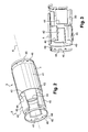
- On a représenté sur les
figures 2 à 6 le stator 3 avec la structure aimantée 5, laquelle comprend six aimants permanents 40 par exemple en ferrite. - La culasse 4 comprend une paroi sensiblement cylindrique de révolution 41 d'axe X réalisée, dans l'exemple décrit, par roulage.
- Les aimants 40 présentent chacun une forme sensiblement trapézoïdale lorsque ceux-ci sont observés suivant un axe perpendiculaire à l'axe longitudinal X de la culasse 4.
- Chaque aimant 40 présente deux faces principales en forme de portions de cylindre coaxiales.
- Chaque aimant 40 présente deux bords latéraux rectilignes 42 faisant un angle alpha non nul avec l'axe longitudinal X.
- Les aimants 40 sont disposés en quinconce, de manière jointive.
- Comme illustré sur la
figure 6 , cet angle alpha est par exemple sensiblement égal à 3° de sorte que des bords d'extrémité axiale 44 des aimants 40 soient décalés axialement d'une distance d d'environ 2 mm, pour un diamètre intérieur Dint de la culasse 4 d'environ de 66 mm. - Dans l'exemple décrit, les aimants 40 sont de mêmes dimensions.
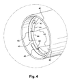
- Ces aimants 40 sont plaqués contre la surface intérieure de la culasse 4 à l'aide de deux éléments de fixation 45 disposés de part et d'autre des aimants 40.
- Chaque élément de fixation 45 comporte une couronne fendue 45 pourvue d'une pluralité de pattes de maintien 47 agencées chacune pour s'appliquer contre le plus grand des deux bords d'extrémité axiale 44 de chacun des aimants 40.
- La couronne 46 et les pattes 47 sont formées par découpe et pliage d'une tôle métallique.
- En variante, cette couronne 46 et les pattes 47 peuvent être réalisées en matière plastique.
- La couronne 46 est en outre pourvue de languettes 48 pour empêcher la rotation des aimants 40, chacune de ces languettes 48 étant en appui contre un bord latéral rectiligne 42 de l'un des aimants 40.
- La couronne 46 est fixée sur la culasse 4 par rivetage, boutonnage, vissage ou collage par exemple.
- Dans l'exemple de mise en oeuvre qui vient d'être décrit, les aimants 40 présentent tous les mêmes dimensions.
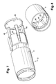
- On ne sort pas du cadre de la présente invention lorsque le stator 3 comporte des aimants de deux types différents, comme illustré sur les
figures 7 et 8 . - Dans cet exemple de mise en oeuvre de l'invention, des aimants 40 de grandes dimensions sont disposés de manière alternée avec des aimants 49 de plus petites dimensions.
- Les aimants 40 et 49 disposés en quinconce présentent des formes trapézoïdales.
- L'aimantation au sein des aimants 40 et 49 peut définir par exemple six pôles magnétiques.
- En variante, le nombre de pôles peut être égal à quatre.
- La direction d'aimantation peut, le cas échéant, varier, notamment continûment, lorsque l'on se déplace sur une circonférence des aimants 40 et 49.
- Dans les exemples qui sont décrits ci-dessus, tous les aimants du stator présentent la même épaisseur mesurée dans une direction radiale.
- En variante, comme illustré sur les
figures 9 à 11 , les aimants 49 de plus petites dimensions présentent une épaisseur radiale plus faible que celle des aimants 40 voisins. - Ces aimants 49 de plus faibles dimensions sont plaqués contre des inserts 50 réalisés en matière plastique.
- Chaque insert 50 présente une forme sensiblement rectangulaire.
- Dans l'exemple de mise en oeuvre des
figures 9 à 11 , les inserts 50 sont formés chacun d'une pièce individuelle. - En variante, comme illustré sur les
figures 12 à 14 , les inserts 50 sont formés sur une pièce commune 51 comportant une couronne fendue 52 sur laquelle se raccordent les inserts 50. - Dans les exemples décrits ci-dessus, les aimants forment une structure aimantée continue sur toute sa circonférence.
- En variante, comme illustré sur les
figures 15 à 17 , les aimants 40 de forme trapézoïdale sont séparés deux à deux par un insert amagnétique 53, par exemple en matière plastique, de forme trapézoïdale complémentaire de la forme des aimants 40. - Ces inserts 53 se raccordent à une couronne fendue 54.
Claims (9)
- Stator (3) de machine électrique tournante, notamment à courant continu, cette machine étant notamment un démarreur (1) de véhicule automobile, le stator comportant :- une culasse (4) comprenant une paroi (41) sensiblement cylindrique présentant un axe longitudinal (X),- au moins un aimant (40) disposé à l'intérieur de la culasse, et comprenant au moins un bord latéral (42) formant avec l'axe longitudinal (X) de la paroi sensiblement cylindrique de la culasse, un angle (alpha) strictement compris entre 0° et 90°,caractérisé par le fait qu'il comporte une pluralité d'aimants permanents (40), notamment de forme trapézoïdale, disposés en quinconce, notamment de manière jointive.
- Stator selon la revendication précédente, caractérisé par le fait que ledit bord latéral (52) est sensiblement rectiligne.
- Stator selon l'une quelconque des revendications précédentes, caractérisé par le fait que l'angle entre ledit bord latéral (42) de l'aimant et l'axe longitudinal (X) de la culasse est compris entre 1° et 20°, étant notamment compris entre 2° et 15°, étant par exemple inférieur à 5°.
- Stator selon l'une quelconque des revendications précédentes, caractérisé par le fait que ledit bord latéral (42) de l'aimant permanent (40) est en appui sur un bord latéral appartenant à l'un d'un aimant permanent voisin et un insert amagnétique (53).
- Stator selon l'une quelconque des revendications précédentes, caractérisé par le fait que l'aimant permanent (40) présente une forme sensiblement trapézoïdale lorsque celui-ci est observé suivant un axe perpendiculaire à l'axe longitudinal de la culasse.
- Stator selon la revendication précédente, caractérisé par le fait que deux aimants permanents (40) voisins présentent des bords d'extrémité axiale (44) décalés axialement d'une distance correspondant à une fraction de la hauteur des aimants permanents, cette distance étant notamment inférieure à 1/5 de la hauteur de l'aimant.
- Stator selon l'une quelconque des revendications précédentes, caractérisé par le fait qu'il comporte au moins un élément de fixation (45) des aimants contre une surface intérieure de la paroi cylindrique (41) de la culasse, cet élément de fixation comprenant au moins une patte de maintien (47), notamment du type découpée dans une tôle.
- Stator selon la revendication précédente, caractérisé par le fait que l'élément de maintien comporte au moins une couronne (46) s'étendant sur au moins une majeure partie d'une circonférence des aimants permanents.
- Machine électrique tournante, notamment démarreur de véhicule automobile, comportant un stator (3) tel que défini dans l'une quelconque des revendications précédentes.
Applications Claiming Priority (1)
| Application Number | Priority Date | Filing Date | Title |
|---|---|---|---|
| FR0856632A FR2936665B1 (fr) | 2008-10-01 | 2008-10-01 | Stator de machine electrique tournante |
Publications (2)
| Publication Number | Publication Date |
|---|---|
| EP2173019A1 true EP2173019A1 (fr) | 2010-04-07 |
| EP2173019B1 EP2173019B1 (fr) | 2011-02-02 |
Family
ID=40809803
Family Applications (1)
| Application Number | Title | Priority Date | Filing Date |
|---|---|---|---|
| EP09171827A Active EP2173019B1 (fr) | 2008-10-01 | 2009-09-30 | Stator de machine électrique tournante |
Country Status (4)
| Country | Link |
|---|---|
| EP (1) | EP2173019B1 (fr) |
| AT (1) | ATE497645T1 (fr) |
| DE (1) | DE602009000700D1 (fr) |
| FR (1) | FR2936665B1 (fr) |
Citations (8)
| Publication number | Priority date | Publication date | Assignee | Title |
|---|---|---|---|---|
| EP0706254A1 (fr) * | 1994-10-05 | 1996-04-10 | Nippondenso Co., Ltd. | Machine électrique tournante et méthode de fabrication de celle-ci |
| EP0895334A2 (fr) * | 1997-07-31 | 1999-02-03 | Denso Corporation | Machine électrique tournante avec une bosse s'étendant radialement vers l'extérieur depuis la culasse |
| US5942873A (en) * | 1997-04-18 | 1999-08-24 | Nakano; Kazuo | Permanent magnet type synchronous machine |
| EP0985334B1 (fr) | 1997-05-30 | 2001-08-01 | Ultra Precision Holding S.A. | Adaptateur pour composants electroniques |
| FR2808937A1 (fr) * | 2000-05-11 | 2001-11-16 | Valeo Systemes Dessuyage | Machine electrique tournante |
| EP1237252A2 (fr) * | 2001-02-23 | 2002-09-04 | Black & Decker Inc. | Arrangement d'aimants pour un moteur et procédé de fabrication |
| US20030094863A1 (en) * | 2001-11-08 | 2003-05-22 | Yoshikazu Kurita | Starter for engine |
| EP1885042A2 (fr) * | 2006-08-04 | 2008-02-06 | Mabuchi Motor Co., Ltd. | Moteur de petite taille avec aimants de champ annulaire |
-
2008
- 2008-10-01 FR FR0856632A patent/FR2936665B1/fr not_active Expired - Fee Related
-
2009
- 2009-09-30 EP EP09171827A patent/EP2173019B1/fr active Active
- 2009-09-30 AT AT09171827T patent/ATE497645T1/de not_active IP Right Cessation
- 2009-09-30 DE DE602009000700T patent/DE602009000700D1/de active Active
Patent Citations (8)
| Publication number | Priority date | Publication date | Assignee | Title |
|---|---|---|---|---|
| EP0706254A1 (fr) * | 1994-10-05 | 1996-04-10 | Nippondenso Co., Ltd. | Machine électrique tournante et méthode de fabrication de celle-ci |
| US5942873A (en) * | 1997-04-18 | 1999-08-24 | Nakano; Kazuo | Permanent magnet type synchronous machine |
| EP0985334B1 (fr) | 1997-05-30 | 2001-08-01 | Ultra Precision Holding S.A. | Adaptateur pour composants electroniques |
| EP0895334A2 (fr) * | 1997-07-31 | 1999-02-03 | Denso Corporation | Machine électrique tournante avec une bosse s'étendant radialement vers l'extérieur depuis la culasse |
| FR2808937A1 (fr) * | 2000-05-11 | 2001-11-16 | Valeo Systemes Dessuyage | Machine electrique tournante |
| EP1237252A2 (fr) * | 2001-02-23 | 2002-09-04 | Black & Decker Inc. | Arrangement d'aimants pour un moteur et procédé de fabrication |
| US20030094863A1 (en) * | 2001-11-08 | 2003-05-22 | Yoshikazu Kurita | Starter for engine |
| EP1885042A2 (fr) * | 2006-08-04 | 2008-02-06 | Mabuchi Motor Co., Ltd. | Moteur de petite taille avec aimants de champ annulaire |
Also Published As
| Publication number | Publication date |
|---|---|
| FR2936665A1 (fr) | 2010-04-02 |
| EP2173019B1 (fr) | 2011-02-02 |
| ATE497645T1 (de) | 2011-02-15 |
| DE602009000700D1 (de) | 2011-03-17 |
| FR2936665B1 (fr) | 2010-10-08 |
Similar Documents
| Publication | Publication Date | Title |
|---|---|---|
| EP2564491B1 (fr) | Machine electrique tournante en particulier pour un demarreur de vehicule automobile | |
| EP1273087B1 (fr) | Machine electrique a ensemble porte-balais et procede d'assemblage d'une machine electrique pourvue d'un tel ensemble | |
| EP1008226A1 (fr) | Alternateur de vehicule ayant un enroulement isole du carter | |
| WO2008074954A1 (fr) | Machine electrique tournante, en particulier pour un demarreur de vehicule automobile | |
| FR2920259A1 (fr) | Machine electrique tournante, en particulier pour un demarreur automobile | |
| WO2018229065A1 (fr) | Machine electrique tournante | |
| EP2901528A1 (fr) | Cage a balai pour porte-balai de machine electrique et porte-balais correspondant | |
| EP2173019B1 (fr) | Stator de machine électrique tournante | |
| EP2446136B1 (fr) | Dispositif a balai pour une machine electrique tournante, notamment un demarreur pour moteur a combustion de vehicule automobile | |
| WO2009068814A1 (fr) | Machine electrique tournante pour vehicule automobile | |
| WO2010000996A2 (fr) | Rotor de machine electrique tournante avec structures interpolaires a masse reduite | |
| EP2145376A2 (fr) | Procede de fabrication d'un rotor de machine electrique tournante, notamment un alternateur | |
| FR2850215A1 (fr) | Armature d'une machine electrique rotative et demarreur comportant l'armature | |
| WO2010010270A2 (fr) | Dispositif a balais pour demarreur de vehicule automobile | |
| FR2925619A1 (fr) | Demarreur de vehicule automobile comportant des moyens d'indexation angulaire de la culasse dans au moins deux positions angulaires de montage sur un palier. | |
| EP3097634B1 (fr) | Dispositif isolant pour collecteur de machine electrique, collecteur et alternateur correspondants | |
| FR2910192A1 (fr) | Machine electrique tournante, en particulier pour un demarreur de vehicule automobile | |
| FR2932325A1 (fr) | Rotor de machine electrique tournante avec structures interpolaires a masse reduite | |
| EP3107193B1 (fr) | Rotor à tôles empilées | |
| EP2452406B1 (fr) | Collecteur de machine electrique tournante pour vehicule automobile | |
| FR2910194A1 (fr) | Machine electrique tournante, notamment pour demarreur de vehicule automobile | |
| FR3083030A1 (fr) | Demarreur ayant un porte balai pour une longueur de balai optimisee | |
| FR2934436A1 (fr) | Dispositif a balais pour demarreur de vehicule automobile | |
| EP2063514A1 (fr) | Stator pour machine électrique tournante, notamment un démarreur | |
| FR2910193A1 (fr) | Marchine electrique tournante, en particulier pour un demarreur de vehicule automobile |
Legal Events
| Date | Code | Title | Description |
|---|---|---|---|
| PUAI | Public reference made under article 153(3) epc to a published international application that has entered the european phase |
Free format text: ORIGINAL CODE: 0009012 |
|
| 17P | Request for examination filed |
Effective date: 20090930 |
|
| AK | Designated contracting states |
Kind code of ref document: A1 Designated state(s): AT BE BG CH CY CZ DE DK EE ES FI FR GB GR HR HU IE IS IT LI LT LU LV MC MK MT NL NO PL PT RO SE SI SK SM TR |
|
| AX | Request for extension of the european patent |
Extension state: AL BA RS |
|
| GRAP | Despatch of communication of intention to grant a patent |
Free format text: ORIGINAL CODE: EPIDOSNIGR1 |
|
| GRAS | Grant fee paid |
Free format text: ORIGINAL CODE: EPIDOSNIGR3 |
|
| GRAA | (expected) grant |
Free format text: ORIGINAL CODE: 0009210 |
|
| AK | Designated contracting states |
Kind code of ref document: B1 Designated state(s): AT BE BG CH CY CZ DE DK EE ES FI FR GB GR HR HU IE IS IT LI LT LU LV MC MK MT NL NO PL PT RO SE SI SK SM TR |
|
| REG | Reference to a national code |
Ref country code: GB Ref legal event code: FG4D Free format text: NOT ENGLISH |
|
| REG | Reference to a national code |
Ref country code: CH Ref legal event code: EP |
|
| REG | Reference to a national code |
Ref country code: IE Ref legal event code: FG4D Free format text: LANGUAGE OF EP DOCUMENT: FRENCH |
|
| REF | Corresponds to: |
Ref document number: 602009000700 Country of ref document: DE Date of ref document: 20110317 Kind code of ref document: P |
|
| REG | Reference to a national code |
Ref country code: DE Ref legal event code: R096 Ref document number: 602009000700 Country of ref document: DE Effective date: 20110317 |
|
| REG | Reference to a national code |
Ref country code: NL Ref legal event code: VDEP Effective date: 20110202 |
|
| LTIE | Lt: invalidation of european patent or patent extension |
Effective date: 20110202 |
|
| PG25 | Lapsed in a contracting state [announced via postgrant information from national office to epo] |
Ref country code: ES Free format text: LAPSE BECAUSE OF FAILURE TO SUBMIT A TRANSLATION OF THE DESCRIPTION OR TO PAY THE FEE WITHIN THE PRESCRIBED TIME-LIMIT Effective date: 20110513 Ref country code: HR Free format text: LAPSE BECAUSE OF FAILURE TO SUBMIT A TRANSLATION OF THE DESCRIPTION OR TO PAY THE FEE WITHIN THE PRESCRIBED TIME-LIMIT Effective date: 20110202 Ref country code: GR Free format text: LAPSE BECAUSE OF FAILURE TO SUBMIT A TRANSLATION OF THE DESCRIPTION OR TO PAY THE FEE WITHIN THE PRESCRIBED TIME-LIMIT Effective date: 20110503 Ref country code: PT Free format text: LAPSE BECAUSE OF FAILURE TO SUBMIT A TRANSLATION OF THE DESCRIPTION OR TO PAY THE FEE WITHIN THE PRESCRIBED TIME-LIMIT Effective date: 20110602 Ref country code: IS Free format text: LAPSE BECAUSE OF FAILURE TO SUBMIT A TRANSLATION OF THE DESCRIPTION OR TO PAY THE FEE WITHIN THE PRESCRIBED TIME-LIMIT Effective date: 20110602 Ref country code: NO Free format text: LAPSE BECAUSE OF FAILURE TO SUBMIT A TRANSLATION OF THE DESCRIPTION OR TO PAY THE FEE WITHIN THE PRESCRIBED TIME-LIMIT Effective date: 20110502 Ref country code: LT Free format text: LAPSE BECAUSE OF FAILURE TO SUBMIT A TRANSLATION OF THE DESCRIPTION OR TO PAY THE FEE WITHIN THE PRESCRIBED TIME-LIMIT Effective date: 20110202 Ref country code: LV Free format text: LAPSE BECAUSE OF FAILURE TO SUBMIT A TRANSLATION OF THE DESCRIPTION OR TO PAY THE FEE WITHIN THE PRESCRIBED TIME-LIMIT Effective date: 20110202 Ref country code: SE Free format text: LAPSE BECAUSE OF FAILURE TO SUBMIT A TRANSLATION OF THE DESCRIPTION OR TO PAY THE FEE WITHIN THE PRESCRIBED TIME-LIMIT Effective date: 20110202 |
|
| PG25 | Lapsed in a contracting state [announced via postgrant information from national office to epo] |
Ref country code: AT Free format text: LAPSE BECAUSE OF FAILURE TO SUBMIT A TRANSLATION OF THE DESCRIPTION OR TO PAY THE FEE WITHIN THE PRESCRIBED TIME-LIMIT Effective date: 20110202 Ref country code: FI Free format text: LAPSE BECAUSE OF FAILURE TO SUBMIT A TRANSLATION OF THE DESCRIPTION OR TO PAY THE FEE WITHIN THE PRESCRIBED TIME-LIMIT Effective date: 20110202 Ref country code: BG Free format text: LAPSE BECAUSE OF FAILURE TO SUBMIT A TRANSLATION OF THE DESCRIPTION OR TO PAY THE FEE WITHIN THE PRESCRIBED TIME-LIMIT Effective date: 20110502 Ref country code: SI Free format text: LAPSE BECAUSE OF FAILURE TO SUBMIT A TRANSLATION OF THE DESCRIPTION OR TO PAY THE FEE WITHIN THE PRESCRIBED TIME-LIMIT Effective date: 20110202 Ref country code: NL Free format text: LAPSE BECAUSE OF FAILURE TO SUBMIT A TRANSLATION OF THE DESCRIPTION OR TO PAY THE FEE WITHIN THE PRESCRIBED TIME-LIMIT Effective date: 20110202 Ref country code: PL Free format text: LAPSE BECAUSE OF FAILURE TO SUBMIT A TRANSLATION OF THE DESCRIPTION OR TO PAY THE FEE WITHIN THE PRESCRIBED TIME-LIMIT Effective date: 20110202 Ref country code: CY Free format text: LAPSE BECAUSE OF FAILURE TO SUBMIT A TRANSLATION OF THE DESCRIPTION OR TO PAY THE FEE WITHIN THE PRESCRIBED TIME-LIMIT Effective date: 20110202 |
|
| REG | Reference to a national code |
Ref country code: IE Ref legal event code: FD4D |
|
| PG25 | Lapsed in a contracting state [announced via postgrant information from national office to epo] |
Ref country code: IE Free format text: LAPSE BECAUSE OF FAILURE TO SUBMIT A TRANSLATION OF THE DESCRIPTION OR TO PAY THE FEE WITHIN THE PRESCRIBED TIME-LIMIT Effective date: 20110202 Ref country code: EE Free format text: LAPSE BECAUSE OF FAILURE TO SUBMIT A TRANSLATION OF THE DESCRIPTION OR TO PAY THE FEE WITHIN THE PRESCRIBED TIME-LIMIT Effective date: 20110202 Ref country code: DK Free format text: LAPSE BECAUSE OF FAILURE TO SUBMIT A TRANSLATION OF THE DESCRIPTION OR TO PAY THE FEE WITHIN THE PRESCRIBED TIME-LIMIT Effective date: 20110202 |
|
| PG25 | Lapsed in a contracting state [announced via postgrant information from national office to epo] |
Ref country code: SK Free format text: LAPSE BECAUSE OF FAILURE TO SUBMIT A TRANSLATION OF THE DESCRIPTION OR TO PAY THE FEE WITHIN THE PRESCRIBED TIME-LIMIT Effective date: 20110202 Ref country code: CZ Free format text: LAPSE BECAUSE OF FAILURE TO SUBMIT A TRANSLATION OF THE DESCRIPTION OR TO PAY THE FEE WITHIN THE PRESCRIBED TIME-LIMIT Effective date: 20110202 Ref country code: RO Free format text: LAPSE BECAUSE OF FAILURE TO SUBMIT A TRANSLATION OF THE DESCRIPTION OR TO PAY THE FEE WITHIN THE PRESCRIBED TIME-LIMIT Effective date: 20110202 |
|
| PLBE | No opposition filed within time limit |
Free format text: ORIGINAL CODE: 0009261 |
|
| STAA | Information on the status of an ep patent application or granted ep patent |
Free format text: STATUS: NO OPPOSITION FILED WITHIN TIME LIMIT |
|
| 26N | No opposition filed |
Effective date: 20111103 |
|
| REG | Reference to a national code |
Ref country code: DE Ref legal event code: R097 Ref document number: 602009000700 Country of ref document: DE Effective date: 20111103 |
|
| BERE | Be: lapsed |
Owner name: VALEO EQUIPEMENTS ELECTRIQUES MOTEUR Effective date: 20110930 |
|
| PG25 | Lapsed in a contracting state [announced via postgrant information from national office to epo] |
Ref country code: MC Free format text: LAPSE BECAUSE OF NON-PAYMENT OF DUE FEES Effective date: 20110930 |
|
| PG25 | Lapsed in a contracting state [announced via postgrant information from national office to epo] |
Ref country code: IT Free format text: LAPSE BECAUSE OF FAILURE TO SUBMIT A TRANSLATION OF THE DESCRIPTION OR TO PAY THE FEE WITHIN THE PRESCRIBED TIME-LIMIT Effective date: 20110202 |
|
| PG25 | Lapsed in a contracting state [announced via postgrant information from national office to epo] |
Ref country code: BE Free format text: LAPSE BECAUSE OF NON-PAYMENT OF DUE FEES Effective date: 20110930 |
|
| PG25 | Lapsed in a contracting state [announced via postgrant information from national office to epo] |
Ref country code: MK Free format text: LAPSE BECAUSE OF FAILURE TO SUBMIT A TRANSLATION OF THE DESCRIPTION OR TO PAY THE FEE WITHIN THE PRESCRIBED TIME-LIMIT Effective date: 20110202 Ref country code: MT Free format text: LAPSE BECAUSE OF FAILURE TO SUBMIT A TRANSLATION OF THE DESCRIPTION OR TO PAY THE FEE WITHIN THE PRESCRIBED TIME-LIMIT Effective date: 20110202 |
|
| PG25 | Lapsed in a contracting state [announced via postgrant information from national office to epo] |
Ref country code: SM Free format text: LAPSE BECAUSE OF FAILURE TO SUBMIT A TRANSLATION OF THE DESCRIPTION OR TO PAY THE FEE WITHIN THE PRESCRIBED TIME-LIMIT Effective date: 20110202 |
|
| PG25 | Lapsed in a contracting state [announced via postgrant information from national office to epo] |
Ref country code: LU Free format text: LAPSE BECAUSE OF NON-PAYMENT OF DUE FEES Effective date: 20110930 |
|
| PG25 | Lapsed in a contracting state [announced via postgrant information from national office to epo] |
Ref country code: TR Free format text: LAPSE BECAUSE OF FAILURE TO SUBMIT A TRANSLATION OF THE DESCRIPTION OR TO PAY THE FEE WITHIN THE PRESCRIBED TIME-LIMIT Effective date: 20110202 |
|
| PG25 | Lapsed in a contracting state [announced via postgrant information from national office to epo] |
Ref country code: HU Free format text: LAPSE BECAUSE OF FAILURE TO SUBMIT A TRANSLATION OF THE DESCRIPTION OR TO PAY THE FEE WITHIN THE PRESCRIBED TIME-LIMIT Effective date: 20110202 |
|
| REG | Reference to a national code |
Ref country code: CH Ref legal event code: PL |
|
| GBPC | Gb: european patent ceased through non-payment of renewal fee |
Effective date: 20130930 |
|
| PG25 | Lapsed in a contracting state [announced via postgrant information from national office to epo] |
Ref country code: LI Free format text: LAPSE BECAUSE OF NON-PAYMENT OF DUE FEES Effective date: 20130930 Ref country code: GB Free format text: LAPSE BECAUSE OF NON-PAYMENT OF DUE FEES Effective date: 20130930 Ref country code: CH Free format text: LAPSE BECAUSE OF NON-PAYMENT OF DUE FEES Effective date: 20130930 |
|
| REG | Reference to a national code |
Ref country code: FR Ref legal event code: PLFP Year of fee payment: 8 |
|
| REG | Reference to a national code |
Ref country code: FR Ref legal event code: PLFP Year of fee payment: 9 |
|
| REG | Reference to a national code |
Ref country code: FR Ref legal event code: PLFP Year of fee payment: 10 |
|
| P01 | Opt-out of the competence of the unified patent court (upc) registered |
Effective date: 20230528 |
|
| PGFP | Annual fee paid to national office [announced via postgrant information from national office to epo] |
Ref country code: DE Payment date: 20250916 Year of fee payment: 17 |
|
| PGFP | Annual fee paid to national office [announced via postgrant information from national office to epo] |
Ref country code: FR Payment date: 20250929 Year of fee payment: 17 |