EP2172825A1 - Route planning device and method, cost evaluation device and mobile body - Google Patents
Route planning device and method, cost evaluation device and mobile body Download PDFInfo
- Publication number
- EP2172825A1 EP2172825A1 EP08778064A EP08778064A EP2172825A1 EP 2172825 A1 EP2172825 A1 EP 2172825A1 EP 08778064 A EP08778064 A EP 08778064A EP 08778064 A EP08778064 A EP 08778064A EP 2172825 A1 EP2172825 A1 EP 2172825A1
- Authority
- EP
- European Patent Office
- Prior art keywords
- node
- path
- cost
- distance
- start point
- Prior art date
- Legal status (The legal status is an assumption and is not a legal conclusion. Google has not performed a legal analysis and makes no representation as to the accuracy of the status listed.)
- Granted
Links
- 238000000034 method Methods 0.000 title claims description 32
- 238000011156 evaluation Methods 0.000 title claims description 17
- 238000004364 calculation method Methods 0.000 claims abstract description 59
- 238000002360 preparation method Methods 0.000 claims description 6
- 238000010586 diagram Methods 0.000 description 71
- 238000012545 processing Methods 0.000 description 12
- 238000007796 conventional method Methods 0.000 description 7
- 230000036544 posture Effects 0.000 description 4
- 230000006399 behavior Effects 0.000 description 3
- 238000004590 computer program Methods 0.000 description 3
- 238000003384 imaging method Methods 0.000 description 3
- 238000004422 calculation algorithm Methods 0.000 description 2
- 238000005516 engineering process Methods 0.000 description 2
- 230000005540 biological transmission Effects 0.000 description 1
- 230000008859 change Effects 0.000 description 1
- 238000004891 communication Methods 0.000 description 1
- 238000010276 construction Methods 0.000 description 1
- 230000000694 effects Effects 0.000 description 1
- 230000006872 improvement Effects 0.000 description 1
- 238000012986 modification Methods 0.000 description 1
- 230000004048 modification Effects 0.000 description 1
- 230000003287 optical effect Effects 0.000 description 1
- 230000008569 process Effects 0.000 description 1
- 230000004044 response Effects 0.000 description 1
- 238000011144 upstream manufacturing Methods 0.000 description 1
Images


Classifications
-
- G—PHYSICS
- G05—CONTROLLING; REGULATING
- G05D—SYSTEMS FOR CONTROLLING OR REGULATING NON-ELECTRIC VARIABLES
- G05D1/00—Control of position, course, altitude or attitude of land, water, air or space vehicles, e.g. using automatic pilots
- G05D1/02—Control of position or course in two dimensions
- G05D1/021—Control of position or course in two dimensions specially adapted to land vehicles
- G05D1/0212—Control of position or course in two dimensions specially adapted to land vehicles with means for defining a desired trajectory
- G05D1/0217—Control of position or course in two dimensions specially adapted to land vehicles with means for defining a desired trajectory in accordance with energy consumption, time reduction or distance reduction criteria
-
- G—PHYSICS
- G05—CONTROLLING; REGULATING
- G05D—SYSTEMS FOR CONTROLLING OR REGULATING NON-ELECTRIC VARIABLES
- G05D1/00—Control of position, course, altitude or attitude of land, water, air or space vehicles, e.g. using automatic pilots
- G05D1/02—Control of position or course in two dimensions
- G05D1/021—Control of position or course in two dimensions specially adapted to land vehicles
- G05D1/0268—Control of position or course in two dimensions specially adapted to land vehicles using internal positioning means
- G05D1/0274—Control of position or course in two dimensions specially adapted to land vehicles using internal positioning means using mapping information stored in a memory device
-
- G—PHYSICS
- G06—COMPUTING; CALCULATING OR COUNTING
- G06Q—INFORMATION AND COMMUNICATION TECHNOLOGY [ICT] SPECIALLY ADAPTED FOR ADMINISTRATIVE, COMMERCIAL, FINANCIAL, MANAGERIAL OR SUPERVISORY PURPOSES; SYSTEMS OR METHODS SPECIALLY ADAPTED FOR ADMINISTRATIVE, COMMERCIAL, FINANCIAL, MANAGERIAL OR SUPERVISORY PURPOSES, NOT OTHERWISE PROVIDED FOR
- G06Q10/00—Administration; Management
- G06Q10/04—Forecasting or optimisation specially adapted for administrative or management purposes, e.g. linear programming or "cutting stock problem"
- G06Q10/047—Optimisation of routes or paths, e.g. travelling salesman problem
Definitions
- the present invention relates to a path planning device and a path planning method for selecting a minimum cost path among paths from a start point to an end point, which are included in an area represented by a grid, a cost evaluation device for use in cost evaluation carried out in the path planning device, and a moving body having the path planning device mounted thereon.
- Patent Document 1 discloses a path planning system for a mobile robot, in which a path for a mobile robot to move from a starting point to a destination is obtained.
- the path planning system includes: grid map generation means that generates a grid map showing the distribution of spaces occupied by an object, which represents positions and postures in terms of probability, by using a geometric map for the object within an environment; Voronoi diagram generation means that generates a Voronoi diagram using distances according to the uncertainty of the positions and postures of the object, based on the generated grip map; and path search means that searches for a path from a given starting point to a destination, assuming that the possibility of collision with the object and a path length are expressed as costs on the generated Voronoi diagram.
- the Voronoi diagram is generated using distances according to the uncertainty of the positions and postures of the object, and the path search is performed by calculating the costs on the weighted Voronoi diagram thus generated, thereby generating a safer path than that obtained by the conventional Voronoi diagram.
- Patent Document 1 Japanese Unexamined Patent Application Publication No. 2005 - 32196
- Fig. 7F is a diagram showing the shortest distance from the start to the goal.
- Figs. 7A to 7E are diagrams each showing the shortest distance in the case where grid points are connected to each other.
- the ideal path shown in Fig. 7F is a path connecting the start and the goal with a straight line.
- the path shown in Fig. 7E is close to the ideal path.
- the paths shown in Figs. 7A to 7D are selected in some cases.
- the path length is represented as the simple sum of segments connecting the grid points, which makes it impossible to recognize that the segment connecting two given points is optimal. Accordingly, in the conventional path search system, the paths shown in Figs. 7A to 7E have the same length, with the result that not the path shown in Fig. 7E but the paths shown in Figs. 7A to 7D are generated. Thus, the conventional path search system has a problem in that the angular resolution of the path is low and it is impossible to search for the grid path that is close to the ideal shortest path.
- the present invention has been made to solve the above-mentioned problems, and therefore an object of the present invention is to provide a path search device and a path search method which are capable of generating an optimal path in a search space represented by a grid, a cost evaluation device for generating the optimal path for use in the path search device, and a moving body having the path search device mounted thereon.
- a path search device that selects a minimum cost path among paths from a start point to an end point, which are included in an area represented by a grid
- the path search device including: a path cost calculation section that calculates a cost of a path from the start point to the end point, assuming that each grid point is a node and that, when a node obtained by tracing back a predetermined number of nodes from a focus node of current interest in a direction toward the start point along the path is a reference node, a cost of an edge extending from the focus node to a neighboring node adjacent to the focus node is a value given by (a first distance representing a shortest distance from the reference node to the neighboring node) - (a second distance representing a shortest distance from the reference node to the focus node); and a path determination section that determines a path according to the cost of the path.
- the cost is obtained based on the first distance from the reference node to the neighboring node (end node which is located at the end of the edge) and based on the second distance from the reference node to the focus node (root node which is located at the root of the edge).
- the reference node is a node obtained by tracing back one node from the focus node, and the cost of the edge is calculated based on the shortest distance among a plurality of nodes.
- the path cost calculation section can calculate the cost of the path from the start point to the end point as the sum of the costs of the edges constituting the path.
- the path cost can be obtained not simply as the distance but as the sum total of edge costs given by (the first distance - the second distance).
- the path cost calculation section can calculate the cost from the start point to the end point by referring to the database storing the first distance and the second distance, or the cost given by (the first distance - the second distance). Reference of the database enables speeding-up of the path cost calculation.
- the path search device can include a database generation section that constructs the database by calculating (the first distance - the second distance), and the database can be generated while executing the path search, for example.
- the path search device can include: an edge generation section that generates edges extending to neighboring nodes located at least forward, diagonally forward right, and diagonally forward left of a focus node, assuming that a minimum cost node among end nodes each located at an end of the edges is the focus node, when a cost from the start point to a given node is a cost of the given node; and an edge cost calculation/readout section that calculates the first distance and the second distance or reads out the first distance and the second distance from a database.
- the path cost calculation section can calculate a cost of a path from the start point to each of the neighboring nodes as a sum of costs of edges constituting the path.
- the path determination section can select a path having a minimum cost from the start point to the end point, when the neighboring node corresponds to the end point.
- each edge is generated from the focus node, and the cost of each edge is obtained, thereby making it possible to obtain the sum total of the costs of the edges constituting the path as the path cost.
- the edge generation section can extend edges to eight neighboring nodes adjacent to the start point, when the focus node corresponds to the start point. Thus, it is possible to extend edges even if the position of the end point with respect to the start point is unknown. Note that it is also possible to extend edges from the start point only in a direction close to the end point.
- the edge cost calculation/readout section can set the cost of the edge extending from the focus node to the neighboring node as a distance between the focus node and the neighboring node, before the number of nodes from the start point to the neighboring node reaches the predetermined number, and can set the cost of the node as a distance unless the number of nodes reaches the predetermined number.
- the path cost calculation section can set the cost of the adjacent node as the sum of distances of the edges constituting the path from the start point to the neighboring node, before the number of nodes from the start point to the neighboring node reaches the predetermined number.
- a cost evaluation device for use in path search for selecting a minimum cost path among paths from a start point to an end point, which are included in an area represented by a grid
- the cost evaluation device including: a distance preparation section that calculates a first distance representing a shortest distance from a reference node to a neighboring node, and a second distance representing a shortest distance from the reference node to a focus node of current interest, or reads out the first distance and the second distance from a database, assuming that each grid point is a node; a node obtained by extending an edge from the focus node is the neighboring node; and a node obtained by tracing back a predetermined number of nodes from the focus node in a direction toward the start point along a path is the reference node; and an edge cost calculation section that calculates a cost of an edge extending from the focus node to the neighboring node as a value given by (the first distance - the second distance).
- a path search method of selecting a minimum cost path among paths from a start point to an end point, which are included in an area represented by a grid the path search method including: a path cost calculation step of calculating a cost of a path from the start point to the end point, assuming that each grid point is a node and that, when a node obtained by tracing back a predetermined number of nodes from a focus node of current interest in a direction toward the start point along the path is a reference node, a cost of an edge extending from the focus node to a neighboring node adjacent to the focus node is a value given by (a first distance representing a shortest distance from the reference node to the neighboring node) - (a second distance representing a shortest distance from the reference node to the focus node); and a path determination step of determining a path according to the cost of the path.
- a path search method of selecting a minimum cost path among paths from a start point to an end point, which are included in an area represented by a grid the path search method including: a first step of extending edges to eight neighboring nodes adjacent to the start point assuming that each grid point is a node, and calculating a distance from the start point to each of the neighboring nodes as a cost of the neighboring node; a second step of extending edges to neighboring nodes located at least forward, diagonally forward right, and diagonally forward left of a focus node, assuming that a minimum cost node among end nodes each located at an end of the edges is the focus node, when a cost from the start point to one node is a cost of the one node, and calculating a cost of each of the neighboring nodes; a third step of selecting a path having a minimum cost from the start point to the end point, when the neighboring node corresponds to the end point; and repeating the second step until the neighbor
- the second step includes: a distance preparation step of calculating a first distance representing a shortest distance from a reference node to the neighboring node, and a second distance representing a shortest distance from the reference node to the focus node, or reading out the first distance and the second distance from a database, assuming that a node obtained by tracing back a predetermined number of nodes from the focus node in a direction toward the start point along a path is the reference node; an edge cost calculation step of calculating a cost of an edge extending from the focus node to the neighboring node as a value given by (the first distance - the second distance); and a path cost calculation step of calculating a cost of a path from the start point to the neighboring node as a sum of costs of edges constituting the path.
- the edge cost is calculated by (the first distance - the second distance), and the processing is repeated while increasing edges until the neighboring node reaches the end point.
- a moving body including: moving means; drive means that drives the moving means; path search means that selects a minimum cost path among paths from a start point to an end point, which are included in a grid space obtained by representing a surrounding environment by a grid; and control means that controls the drive means based on a result of path search carried out by the path search means.
- the path search means includes: path cost calculation means that calculates a cost of a path from the start point to the end point, assuming that each grid point is a node and that, when a node obtained by tracing back a predetermined number of nodes from a focus node of current interest in a direction toward the start point along the path is a reference node, a cost of an edge extending from the focus node to a neighboring node adjacent to the focus node is a value given by (a first distance representing a shortest distance from the reference node to the neighboring node) - (a second distance representing a shortest distance from the reference node to the focus node); and path determination means that determines a path according to the cost of the path.
- the path search means evaluates the costs uniformly as the distance of each edge
- the angular resolution of the path is improved by the more detailed cost evaluation based on the pattern of the edges, and a more ideal path that is close to the shortest distance can be generated. This enables the moving body to exhibit a more natural movement operation.
- a path search device and a path search method which are capable of generating an optimal path in a search space represented by a grid, a cost evaluation device for generating an optimal path for use in the path search device, and a moving body having the path search device mounted thereon.
- the present invention is applied to a path search device mounted on a robot or the like.
- the path search device generates a grid path, which is as close to the ideal shortest distance as possible, by path searching in a grid-like search space. While consideration is given to a segment length of a path as well as passing points on the path, a cost of each edge (segment) in the path is evaluated.
- a robot having such a path search device mounted thereon is first described.
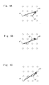
- Fig. 1 is a perspective view showing a robot according to an embodiment of the present invention.
- a robot 1 includes a head unit 2, two right and left arm units 3a and 3b, and two right and left leg units 4a and 4b, each of which is coupled to a predetermined position of a trunk unit 5.
- the robot 1 according to this embodiment is structured to be movable by means of wheels which are respectively incorporated in the leg units 4a and 4b.
- the robot may be a bipedal or quadrupedal walking type robot.
- the head unit 2 includes an imaging section 6, and thus is capable of taking images of surroundings within a predetermined range. Further, the head unit 2 is provided with a microphone, a speaker, and the like, which are not shown, and thus is capable of recognizing an utterance of a user and responding to the utterance.
- the head unit 2 is connected to the trunk unit 5 so as to be rotatable in the horizontal direction in a plane parallel to a floor surface. The head unit 2 is rotated to change an imaging range depending on the situation, thereby making it possible to take images of the surrounding environment.
- An arithmetic processing section which is included in a control section incorporated in the trunk unit 5 controls the amount of driving force to joint portions included in the arm units 3a and 3b and to the wheels included in the leg units 4a and 4b, according to a predetermined control program, and determines a joint driving angle of each joint and a rotation angle of each wheel, with the result that the arm units 3a and 3b and the leg units 4a and 4b take any desired position and posture.
- Fig. 2 is a block diagram showing the robot according to this embodiment.
- the robot 1 includes a control section 101, an input/output section 102, a drive section 103, a power supply section 104, and an external storage section 105.
- the input/output section 102 includes: a camera 121 including a charge coupled device (CCD) for picking up images of the surroundings; one or a plurality of built-in microphones 122 for collecting ambient sounds; a speaker 123 for outputting a voice and having a conversation with the user, for example; an LED 124 for responding to the user and expressing feelings or the like; and a sensor section 125 including a touch sensor.
- CCD charge coupled device
- the drive section 103 includes a motor 131 and a driver 132 that drives the motor, and causes the leg units 4a and 4b and the arm units 3a and 3b to operate in response to an instruction or the like from the user.
- the power supply section 104 includes a battery 141 and a battery control section 142 that controls charge/discharge thereof, and supplies power to each section.
- the external storage section 105 includes an HDD, an optical disk, and a magnet-optical disk, which are detachably mounted, to store various programs, control parameters, and the like, and supplies the programs and data to a memory (not shown) and the like provided in the control section 101, as needed.
- the control section includes a central processing unit (CPU), a read only memory (ROM), a random access memory (RAM), and an interface for wireless communication, and controls various operations of the robot 1.
- the control section 101 includes: an image recognition module 12 that analyzes the images obtained by the camera 121, according to a control program stored in the ROM, for example; a path search module 13 that performs a path search based on an image recognition result; a behavior determination module 14 that selects a behavior to be executed based on various recognition results; and a voice recognition module 15 that performs voice recognition.
- the path search module 13 generates a search path that is close to the ideal path, and the drive section 103 is controlled based on the generated path.
- the robot 1 exhibits a more natural movement.
- the path search module 13 approximates a movement space in a grid-like form, and searches for a path to be taken.
- the path search module according to this embodiment is described in detail.
- Fig. 3 is a diagram showing details of the path search module according to this embodiment.
- the path search module 13 includes a path output section 20 and a distance/cost database (DB) 30.
- the distance/cost DB 30 stores costs from one grid point to another grid point and distances between grid points, which are calculated in advance.
- each grid point is a node; a node to which an edge extends from a focus node of current interest is a neighboring node; and a node obtained by tracing back a predetermined number of nodes from the focus node in a direction toward the start point along the path is a reference node, a first distance representing the shortest distance from the reference node to a neighboring node, and a second distance representing the shortest distance from the reference node to the focus node are stored.
- a cost of an edge extending from the focus node to the neighboring node can be obtained based on the first distance from the reference node to the neighboring node (end node which is located at the end of the edge) and the second distance from the reference node to the focus node (root node positioned at the root of the edge).
- the reference node is a node obtained by tracing back a predetermined number of nodes from the focus node.
- each edge Since the cost of each edge is calculated based on the shortest distance among a plurality of nodes, more detailed cost evaluation can be made based on a pattern of edges, compared to the case of evaluating costs uniformly as a distance of each edge, and the angular resolution of the path is improved, which results in generation of the path that is closer to the ideal shortest distance.
- the path output section 20 includes an edge generation section 21, an edge cost calculation/readout section 22, a path cost calculation section 23, and a path determination section 24. Note that, in this embodiment, a description is given assuming that the distance/cost DB 30 storing the costs and distances is provided and that the path output section 20 refers to the data as necessary to carry out a path search. Alternatively, the path output section 20 may calculate the costs and distances as needed. Further, the distance/cost DB 30 can be constructed by the edge cost calculation/readout section 22 and the path cost calculation section 23 of the path output section 20.
- the environment is recognized as a search space represented by a grid.
- a problem with a robot apparatus is reduced to a problem of searching assuming that each grid point is a node, and an optimal path can be obtained by well-known algorithms such as Dijkstra's algorithm, A* search, and DP matching.
- the distance between nodes and the cost thereof are calculated and registered in the distance/cost DB 30. Note that, when the robot detects a new environment, a distance between nodes and a cost thereof in the environment may be input from the outside.
- processings such as edge generation, edge cost readout/calculation, path cost calculation, and path determination are carried out at rates in a range from once every several milliseconds to once every several seconds, and a path is generated at each of the timings. Note that it is assumed that obstacle information and the like are input as information from the image recognition module and the sensor at each of the timings. Each block is described in detail below.
- a cost from the start point to one node is set as a cost of the one node, it is assumed that a node having a minimum cost among end nodes, each of which is located at the end of each edge, is a focus node, and the edge generation section 21 generates edges extending to neighboring nodes which are positioned at least forward, diagonally forward right, and diagonally forward left of the focus node.
- the term "forward" means a direction of an edge entering the focus node.
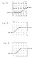
- Figs. 4 and 5 are pattern diagrams for explaining edges and costs thereof.
- the edge generation section 21 generates edges in three directions, i.e., forward, diagonally forward right, and diagonally forward left of the node of interest.
- Figs. 4 and 5 each show 4x4 grid points (n1 to n16).
- a forward node corresponds to the node n8;
- a diagonally forward right node corresponds to the node n4;
- a diagonally left node corresponds to the node n12.
- the edge generation section 21 generates edges extending from the node n7 to the nodes n4, n8, and n12.
- edges are generated for all the eight neighboring nodes that are adjacent to each other vertically, horizontally, and diagonally, instead of generating edges in three directions.
- edges are generated only in three directions, i.e., forward, diagonally forward right, and diagonally forward left directions for the nodes other than the start point, but edges may be generated for all the eight adjacent neighboring nodes with respect to all the nodes.
- five edges extending to the forward, diagonally forward right, and diagonally forward left nodes as well as right-hand and left-hand nodes may be generated.
- edges are generated only in three directions as in this embodiment, the amount of calculation is reduced, which leads to speeding-up of processing. Further, though the edges extending from the start point to all the eight adjacent neighboring nodes are generated in this embodiment, a direction from the start point to the end point may be determined to generate edges for a part of neighboring nodes located in directions that are close to the direction thus determined.
- the edge generation section 21 generates edges extending from the focus node to three neighboring nodes.
- cost refers to a cost from the start point to the node. After edges are generated, a node having a least node cost among node costs of all the end nodes extending from currently existing edges is selected, and edges are generated in a similar manner. Such processing is repeated.
- the edge cost calculation/readout section 22 includes: a distance preparation section 22a that calculates the first distance representing the shortest distance from the reference node to the neighboring node and the second distance representing the shortest distance from the reference node to the focus node, or reads out the first and second distances from the database; and an edge cost calculation section 22b that calculates the cost of each edge extending from the focus node to the neighboring node as given by (the first distance - the second distance).
- the edge cost may be calculated in advance with respect to each pattern and may be stored in the distance/cost DB 30. In this case, it is not necessary to provide the edge cost calculation section 22b.
- the edge cost is evaluated (calculated) using the shape of each edge of a path reaching a node of interest.
- the pattern of the edge shape depends on how many edges are traced back and evaluated. As the path length to be evaluated is increased (the number of edges is increased), the angular resolution of the path, which is described later, is improved.
- Figs. 6A to 6H there are eight path patterns each representing an end node (neighboring node) g3 of an edge extending from a node g2 of interest.
- the node obtained by tracing back a predetermined number of nodes from the node g2 in the direction toward the start point along the path is set as a reference node.
- the node g1 which is obtained by tracing back two nodes (edges) is set as the reference node.
- the cost of the focus node g2 ⁇ the end node g3 can be obtained based on a distance from the reference node g1 to the end node g3 and a distance from the reference node g1 to the focus node g2. Note that, though the case of tracing back two edges is described in this embodiment, it is possible to trace back three edges or more, or only one edge.
- each edge cost is described in detail.
- the node n7 shown in Fig. 4 is a focus node and the nodes n12, n8, n4 are end nodes of the edges each extending from the node n7, edges E1, E2, and E2 are generated from the node n7 by the edge generation section 21.
- a description is given of a method of calculating the cost of the edge E1 of n7 ⁇ n12.
- the reference node corresponds to the node n5 which is obtained by tracing back two edges from the node n7.
- a distance L1 from the reference node n5 to the node n12, which is the end of the edge, is read out from the distance/cost DB 30.
- the distance L1 represents the shortest distance between the nodes n5 ⁇ n12.
- the distance L2 represents the shortest distance between the nodes n5 ⁇ n7.
- the distance is defined as the second distance. In this example, the distance L2 is "2".
- the path cost calculation section 23 calculates the cost from the start point to the end node of each edge generated by the edge generation section 21.
- the costs of the edges may be read out and added to each other.
- the cost between the nodes n5 ⁇ n6 and the cost between the nodes n6 ⁇ n7 vary depending on the reference node for the nodes n5 and n6.
- the path determination section 24 selects a minimum cost path from the start point to the end point.
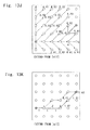
- Figs. 7A to 7F are diagrams each showing a path from the node n7 as a start point to a node n24 as an end point.
- the path determination section 24 selects a path deviating from the ideal paths as shown in Figs. 7A to 7D in some cases.
- the path shown in Fig. 7E is obtained as a minimum cost path as a result of the path calculation executed by the path cost calculation section 23 according to this embodiment.
- the path shown in Fig. 7F which is obtained by simply connecting these nodes with a straight line while ignoring the other nodes, is the ideal shortest path.
- the cost is evaluated based on a difference between the distance from the reference node to the end node of the edge and the distance from the reference node to the root of the edge by tracing back to the reference node, thereby enabling selection of the path, as shown in Fig. 7E , which is closest to the ideal shortest path shown in Fig. 7F .
- edges can be extended from a given node to eight adjacent neighboring nodes. In this case, an angle formed between the edges is 45° at minimum.
- four patterns are obtained within the range of 45°as shown in Figs. 6H , 6B , 6C , and 6D . That is, a resolution of about 45/4 ⁇ 11.3° is obtained, which is four times as high as that obtained in the case of expressing the path using one edge.
- a path with a turning angle of the robot being smaller than 45° can be generated. Accordingly, the robot can move smoothly without sharp turning.
- Figs. 8 and 9 are diagrams showing a movement path of a conventional robot and a movement path of a robot according to this embodiment, respectively.
- the conventional robot apparatus can only take paths for turning diagonally right or left by 45° or 90°.
- the path can be expressed using three edges by tracing back two edges as in this embodiment, the robot can turn with two angles between 0 to 45°, that is, at about 11.3° and about 22.6° as shown in Fig. 9 , and a smoothly curved path can be depicted, thereby enabling the robot apparatus to express a natural movement operation.
- Fig. 10 is a flowchart showing a path determination method according to an embodiment of the present invention.
- Fig. 11 is a flowchart showing an edge cost calculation method.
- Figs. 12A to 12I are diagrams each showing the path search method according to this embodiment.
- Figs. 13A to 13K are diagrams each showing the path search method according to the prior art.
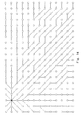
- Fig. 14 is a diagram showing paths generated by the path search method according to this embodiment.
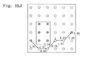
- Figs. 15A to 17J are diagrams each showing the path search method according to this embodiment in the case where an obstacle is present.
- the edge generation section 21 generates edges for all the eight neighboring nodes adjacent to the start point node n7. Note that, in this example, it is impossible to extend edges leftward, upper left, and lower left, because a boundary of the grid area is present on the left side. Thus, edges extending from the start point node n7 to the nodes n1, n2, n8, n14, and n13 are generated. Then, the edge cost calculation/readout section 22 calculates each cost assuming that each cost of the edges extending from the start point n7, which is the focus node, to the subsequent nodes n1, n2, n8, n14, and n13 is equal to the distance thereof.
- the costs of the edges from the start point n7 correspond to the costs of the nodes n1, n2, n8, n14, and n13. That is, the edge cost calculation/readout section 22 reads out the distance from the start point node n7.
- the edge generation section 21 selects a minimum cost node among end nodes of the edges (Step S3).
- the costs from the start point to the nodes n1, n2, n8, n14, and n13 are equal to the distances thereof, and thus the costs are 1, 1.41, 1, 1.41, and 1.
- the edge generation section 21 selects the minimum cost nodes n8 and n13 among the nodes. Note that the n1 is located on the outermost periphery of the grid and no further cost calculation can be made. Thus, the node is excluded from the target of the calculation.
- the edge generation section 21 extends the edges in three directions, i.e., forward, diagonally forward right, and diagonally forward left directions from the nodes n8 and n13 (Step S4).
- the edge cost calculation/readout section 22 determines whether a node number N obtained from the start point to the end node of each edge is equal to or greater than 3, before calculating the cost of each edge. In this embodiment, since the cost is evaluated by tracing back two edges from the node of interest, the cost calculation method similar to the conventional method is employed before the number N from the start point to the end node is equal to or greater than 3.
- Nodes having a second minimum cost of 1.41 are the nodes n2 and n14 (Step S3).
- edges extend from the nodes n2 and n14 to diagonally forward right, the forward node, and the diagonally forward left node (Step S4).
- the diagonally forward right node from the node n2 is not present and the diagonally forward left node corresponds to the node n3.
- an edge extends from the node n8 to the node n3.
- a path having a lower node cost is adopted. It is assumed that, when there are paths having the same node cost, a path extending first is adopted.
- the edge cost calculation/readout section 22 selects the nodes n9 and n19 in the state shown in Fig. 12B . Then, as shown in Fig. 12C , edges extend from the nodes n9 and n19 to the forward and diagonally forward left and right nodes. While each edge cost is calculated next, it is first determined whether the number of nodes from the start point node n7 is equal to or greater than 3 with respect to the end nodes n4, n10, n25, and n26 extending from the edges. Here, the number of nodes is 3, and the flow proceeds to Step S6.
- each edge pattern is checked by tracing back two edges from the nodes n9 and n19 of current interest.
- the node n7 start point node
- the edge patterns correspond to patterns of the end nodes n4, n10, and n16 from the reference node n7. Based on the edge patterns, the costs of the end nodes n4, n10, and n16 are calculated (Step S7).
- the costs of the end nodes n4, n10, and n16 can be calculated by the path cost calculation section 23, based on (cost from the start point to the reference node) + (cost obtained based on the edge pattern from the reference node to the end node).
- the cost from the start point to the reference node may be obtained in such a manner that the edge cost calculation/readout section 22 reads out the costs of the edges constituting the path from the start point to the reference node, from the distance/cost DB 30, and adds the costs.
- the costs of the end nodes n4, n10, and n16 are obtained as 3.16, 3, and 3.16, respectively.
- the costs of the end nodes n25 and n26 are obtained as 3 and 3.16, respectively.
- the reference node for the focus node n9 corresponds to the node n7 which is the start point.
- the cost of the edge between the nodes n9 ⁇ n4 is obtained.
- the distances L1 and L2 and the cost of each edge are registered in the distance/cost DB 30, thereby enabling construction of the database.
- the edge cost calculation/readout section 22 may calculate the cost of each edge in a manner as described above, or may read out the distances L1 and L2 from the distance/cost DB 30 to calculate L1 - L2.
- the distances and costs are calculated with respect to all the nodes (Steps S15 and S16).
- the costs of the nodes n4, n10, and n16 are 3.16, 3, and 3.16, respectively.
- the cost of the node n26 is 3.16
- the cost of the node n25 is 3.
- the cost of the node n27 is obtained by extending the edge from the node n20 to the node 27.
- the path having the edge extending from the node n21 to the node n27 is generated.
- the path having the edge extending from the node n20 to the node n27 is generated earlier.
- the path passing through the node n21 has a lower cost of the node n27, the path from the node n20 is not adopted as the path for the node n27, and the cost from the node 21 is adopted.
- Figs. 13A to 13K when the path search is carried out by using the conventional method, the cost as shown in Fig. 13K is extracted. This is because the path has the same cost as that of the ideal path indicated by the dashed line according to the conventional method.
- the node of the edge is calculated based on the distance from the reference node to the end node of the edge and the distance from the reference node to the root node, the path that is closest to the ideal path is generated.
- Fig. 14 is a diagram showing paths generated according to the path search method according to this embodiment from a start point ST. Particularly when the end point is not set, paths are generated in the manner as shown in Fig. 14 .
- Figs. 15A to 15J each show a path search result in the case where an obstacle is present.
- a path (n7 ⁇ n13 ⁇ n19 ⁇ n26 ⁇ n27 ⁇ n22) is generated in a direction toward the end point from above the obstacle 43, and a path (n7 ⁇ n2 ⁇ n3 ⁇ n10 ⁇ n11 ⁇ n18) is generated in the direction toward the end point from below the obstacle 43.
- the path generated in the direction toward the end point from below first reaches the end point n18.
- the cost of the edge extending from the focus node to the neighboring node is not obtained simply as the distance, but is obtained based on the first distance from the reference node to the neighboring node (end node) and the second distance from the reference node to the focus node (root node).
- the reference node is a node obtained by tracing back at least one node from the focus node, and the cost of each edge is calculated based on the shortest distance among a plurality of nodes.
- the present invention is not limited to the above embodiments, and various modifications can be made as a matter of course without departing from the gist of the present invention.
- the above embodiments describe a hardware configuration, but the present invention is not limited thereto. It is possible to achieve arbitrary processing by causing a central processing unit (CPU) to execute a computer program. In this case, it is possible to provide a computer program recorded on a recording medium. Also, it is possible to provide a computer program transmitted through transmission media such as the Internet.
- CPU central processing unit
- the present invention is widely applicable to, for example, a path planning device and a path planning method for selecting a minimum cost path among paths from a start point to an end point, which are included in an area represented by a grid, a cost evaluation device for use in cost evaluation carried out in the path planning device, and a moving body having the path planning device mounted thereon.
Landscapes
- Engineering & Computer Science (AREA)
- Business, Economics & Management (AREA)
- Radar, Positioning & Navigation (AREA)
- Human Resources & Organizations (AREA)
- Physics & Mathematics (AREA)
- General Physics & Mathematics (AREA)
- Strategic Management (AREA)
- Aviation & Aerospace Engineering (AREA)
- Remote Sensing (AREA)
- Automation & Control Theory (AREA)
- Economics (AREA)
- Operations Research (AREA)
- Game Theory and Decision Science (AREA)
- Entrepreneurship & Innovation (AREA)
- Marketing (AREA)
- Development Economics (AREA)
- Quality & Reliability (AREA)
- Tourism & Hospitality (AREA)
- General Business, Economics & Management (AREA)
- Theoretical Computer Science (AREA)
- Control Of Position, Course, Altitude, Or Attitude Of Moving Bodies (AREA)
- Management, Administration, Business Operations System, And Electronic Commerce (AREA)
- Navigation (AREA)
- Manipulator (AREA)
Abstract
Description
- The present invention relates to a path planning device and a path planning method for selecting a minimum cost path among paths from a start point to an end point, which are included in an area represented by a grid, a cost evaluation device for use in cost evaluation carried out in the path planning device, and a moving body having the path planning device mounted thereon.
- As a conventional path search device,
Patent Document 1 discloses a path planning system for a mobile robot, in which a path for a mobile robot to move from a starting point to a destination is obtained. The path planning system includes: grid map generation means that generates a grid map showing the distribution of spaces occupied by an object, which represents positions and postures in terms of probability, by using a geometric map for the object within an environment; Voronoi diagram generation means that generates a Voronoi diagram using distances according to the uncertainty of the positions and postures of the object, based on the generated grip map; and path search means that searches for a path from a given starting point to a destination, assuming that the possibility of collision with the object and a path length are expressed as costs on the generated Voronoi diagram. - In this configuration, the Voronoi diagram is generated using distances according to the uncertainty of the positions and postures of the object, and the path search is performed by calculating the costs on the weighted Voronoi diagram thus generated, thereby generating a safer path than that obtained by the conventional Voronoi diagram.
- As described above, as a conventional path planning technology, a technology is known in which a movement space is approximated in a grid pattern to evaluate the cost of each path connecting grid points adjacent to each other, as disclosed in the above-mentioned
Patent Document 1. In such a path search system, the searched path is represented as an assembly of segments each connecting grid points adjacent to each other. Accordingly, the cost of each path is evaluated as the sum of segments.
[Patent Document 1]
Japanese Unexamined Patent Application Publication No.2005 - 32196 - Here, if the cost evaluation is performed based on only the segment length, there may be multiple shortest paths when the shortest path search is carried out.
Fig. 7F is a diagram showing the shortest distance from the start to the goal.Figs. 7A to 7E are diagrams each showing the shortest distance in the case where grid points are connected to each other. There is no difference in cost among five paths shown inFigs. 7A to 7E . The ideal path shown inFig. 7F is a path connecting the start and the goal with a straight line.
Among the five paths shown inFigs. 7A to 7E , the path shown inFig. 7E is close to the ideal path. In the conventional path search system, however, the paths shown inFigs. 7A to 7D are selected in some cases. When the path search system is mounted on a robot, for example, there is a problem in that the robot exhibits an unnatural movement. - That is, in a search space discretized in a grid pattern, the path length is represented as the simple sum of segments connecting the grid points, which makes it impossible to recognize that the segment connecting two given points is optimal. Accordingly, in the conventional path search system, the paths shown in
Figs. 7A to 7E have the same length, with the result that not the path shown inFig. 7E but the paths shown inFigs. 7A to 7D are generated.
Thus, the conventional path search system has a problem in that the angular resolution of the path is low and it is impossible to search for the grid path that is close to the ideal shortest path. - The present invention has been made to solve the above-mentioned problems, and therefore an object of the present invention is to provide a path search device and a path search method which are capable of generating an optimal path in a search space represented by a grid, a cost evaluation device for generating the optimal path for use in the path search device, and a moving body having the path search device mounted thereon.
- According to the present invention, there is provided a path search device that selects a minimum cost path among paths from a start point to an end point, which are included in an area represented by a grid, the path search device including: a path cost calculation section that calculates a cost of a path from the start point to the end point, assuming that each grid point is a node and that, when a node obtained by tracing back a predetermined number of nodes from a focus node of current interest in a direction toward the start point along the path is a reference node, a cost of an edge extending from the focus node to a neighboring node adjacent to the focus node is a value given by (a first distance representing a shortest distance from the reference node to the neighboring node) - (a second distance representing a shortest distance from the reference node to the focus node); and a path determination section that determines a path according to the cost of the path.
- According to the present invention, instead of simply setting the cost of the edge extending from the focus node to the neighboring node as a distance, the cost is obtained based on the first distance from the reference node to the neighboring node (end node which is located at the end of the edge) and based on the second distance from the reference node to the focus node (root node which is located at the root of the edge). The reference node is a node obtained by tracing back one node from the focus node, and the cost of the edge is calculated based on the shortest distance among a plurality of nodes. Accordingly, compared to the case of evaluating the costs uniformly as the distance of each edge, more detailed cost evaluation can be made based on the pattern of the edges, and the angular resolution of the path is improved, thereby enabling the generation of the path that is close to the ideal shortest distance.
- Further, the path cost calculation section can calculate the cost of the path from the start point to the end point as the sum of the costs of the edges constituting the path. The path cost can be obtained not simply as the distance but as the sum total of edge costs given by (the first distance - the second distance).
- Further, the path cost calculation section can calculate the cost from the start point to the end point by referring to the database storing the first distance and the second distance, or the cost given by (the first distance - the second distance). Reference of the database enables speeding-up of the path cost calculation.
- Furthermore, the path search device can include a database generation section that constructs the database by calculating (the first distance - the second distance), and the database can be generated while executing the path search, for example.
- Further, the path search device can include: an edge generation section that generates edges extending to neighboring nodes located at least forward, diagonally forward right, and diagonally forward left of a focus node, assuming that a minimum cost node among end nodes each located at an end of the edges is the focus node, when a cost from the start point to a given node is a cost of the given node; and an edge cost calculation/readout section that calculates the first distance and the second distance or reads out the first distance and the second distance from a database. The path cost calculation section can calculate a cost of a path from the start point to each of the neighboring nodes as a sum of costs of edges constituting the path. The path determination section can select a path having a minimum cost from the start point to the end point, when the neighboring node corresponds to the end point.
Thus, each edge is generated from the focus node, and the cost of each edge is obtained, thereby making it possible to obtain the sum total of the costs of the edges constituting the path as the path cost. - Further, the edge generation section can extend edges to eight neighboring nodes adjacent to the start point, when the focus node corresponds to the start point. Thus, it is possible to extend edges even if the position of the end point with respect to the start point is unknown. Note that it is also possible to extend edges from the start point only in a direction close to the end point.
- Furthermore, the edge cost calculation/readout section can set the cost of the edge extending from the focus node to the neighboring node as a distance between the focus node and the neighboring node, before the number of nodes from the start point to the neighboring node reaches the predetermined number, and can set the cost of the node as a distance unless the number of nodes reaches the predetermined number.
- Likewise, the path cost calculation section can set the cost of the adjacent node as the sum of distances of the edges constituting the path from the start point to the neighboring node, before the number of nodes from the start point to the neighboring node reaches the predetermined number.
- According to the present invention, there is provided a cost evaluation device for use in path search for selecting a minimum cost path among paths from a start point to an end point, which are included in an area represented by a grid, the cost evaluation device including: a distance preparation section that calculates a first distance representing a shortest distance from a reference node to a neighboring node, and a second distance representing a shortest distance from the reference node to a focus node of current interest, or reads out the first distance and the second distance from a database, assuming that each grid point is a node; a node obtained by extending an edge from the focus node is the neighboring node; and a node obtained by tracing back a predetermined number of nodes from the focus node in a direction toward the start point along a path is the reference node; and an edge cost calculation section that calculates a cost of an edge extending from the focus node to the neighboring node as a value given by (the first distance - the second distance).
- According to the present invention, there is provided a path search method of selecting a minimum cost path among paths from a start point to an end point, which are included in an area represented by a grid, the path search method including: a path cost calculation step of calculating a cost of a path from the start point to the end point, assuming that each grid point is a node and that, when a node obtained by tracing back a predetermined number of nodes from a focus node of current interest in a direction toward the start point along the path is a reference node, a cost of an edge extending from the focus node to a neighboring node adjacent to the focus node is a value given by (a first distance representing a shortest distance from the reference node to the neighboring node) - (a second distance representing a shortest distance from the reference node to the focus node); and a path determination step of determining a path according to the cost of the path.
- According to the present invention, there is provided a path search method of selecting a minimum cost path among paths from a start point to an end point, which are included in an area represented by a grid, the path search method including: a first step of extending edges to eight neighboring nodes adjacent to the start point assuming that each grid point is a node, and calculating a distance from the start point to each of the neighboring nodes as a cost of the neighboring node; a second step of extending edges to neighboring nodes located at least forward, diagonally forward right, and diagonally forward left of a focus node, assuming that a minimum cost node among end nodes each located at an end of the edges is the focus node, when a cost from the start point to one node is a cost of the one node, and calculating a cost of each of the neighboring nodes; a third step of selecting a path having a minimum cost from the start point to the end point, when the neighboring node corresponds to the end point; and repeating the second step until the neighboring node reaches the end point. The second step includes: a distance preparation step of calculating a first distance representing a shortest distance from a reference node to the neighboring node, and a second distance representing a shortest distance from the reference node to the focus node, or reading out the first distance and the second distance from a database, assuming that a node obtained by tracing back a predetermined number of nodes from the focus node in a direction toward the start point along a path is the reference node; an edge cost calculation step of calculating a cost of an edge extending from the focus node to the neighboring node as a value given by (the first distance - the second distance); and a path cost calculation step of calculating a cost of a path from the start point to the neighboring node as a sum of costs of edges constituting the path.
- According to the present invention, the edge cost is calculated by (the first distance - the second distance), and the processing is repeated while increasing edges until the neighboring node reaches the end point. Thus, the costs obtained in the path search can be correctly evaluated, which leads to an improvement of the angular resolution of the path.
- According to the present invention, there is provided a moving body including: moving means; drive means that drives the moving means; path search means that selects a minimum cost path among paths from a start point to an end point, which are included in a grid space obtained by representing a surrounding environment by a grid; and control means that controls the drive means based on a result of path search carried out by the path search means. The path search means includes: path cost calculation means that calculates a cost of a path from the start point to the end point, assuming that each grid point is a node and that, when a node obtained by tracing back a predetermined number of nodes from a focus node of current interest in a direction toward the start point along the path is a reference node, a cost of an edge extending from the focus node to a neighboring node adjacent to the focus node is a value given by (a first distance representing a shortest distance from the reference node to the neighboring node) - (a second distance representing a shortest distance from the reference node to the focus node); and path determination means that determines a path according to the cost of the path.
- According to the present invention, compared to the case where the path search means evaluates the costs uniformly as the distance of each edge, the angular resolution of the path is improved by the more detailed cost evaluation based on the pattern of the edges, and a more ideal path that is close to the shortest distance can be generated. This enables the moving body to exhibit a more natural movement operation.
- According to the present invention, it is possible to provide a path search device and a path search method which are capable of generating an optimal path in a search space represented by a grid, a cost evaluation device for generating an optimal path for use in the path search device, and a moving body having the path search device mounted thereon.
-
-
Fig. 1 is a perspective view showing a bipedal walking type robot according to an embodiment of the present invention; -
Fig. 2 is a block diagram showing the robot according to an embodiment of the present invention; -
Fig. 3 is a diagram showing details of a path search module according to an embodiment of the present invention; -
Fig. 4 is a pattern diagram for explaining edges for use in path determination processing of a path determination device according to an embodiment of the present invention, and costs thereof; -
Fig. 5 is also a pattern diagram for explaining edges for use in path determination processing of a path determination device according to an embodiment of the present invention, and costs thereof; -
Fig. 6A is a diagram showing the shape of edges in the case of tracing back two edges; -
Fig. 6B is a diagram showing the shape of edges in the case of tracing back two edges; -
Fig. 6C is a diagram showing the shape of edges in the case of tracing back two edges; -
Fig. 6D is a diagram showing the shape of edges in the case of tracing back two edges; -
Fig. 6E is a diagram showing the shape of edges in the case of tracing back two edges; -
Fig. 6F is a diagram showing the shape of edges in the case of tracing back two edges; -
Fig. 6G is a diagram showing the shape of edges in the case of tracing back two edges; -
Fig. 6H is a diagram showing the shape of edges in the case of tracing back two edges; -
Fig. 7A is a diagram showing a path from a node n7 as a start point to a node n24 as an end point; -
Fig. 7B is a diagram showing a path from the node n7 as the start point to the node n24 as the end point; -
Fig. 7C is a diagram showing a path from the node n7 as the start point to the node n24 as the end point; -
Fig. 7D is a diagram showing a path from the node n7 as the start point to the node n24 as the end point; -
Fig. 7E is a diagram showing a path from the node n7 as the start point to the node n24 as the end point; -
Fig. 7F is a diagram showing a path from the node n7 as the start point to the node n24 as the end point; -
Fig. 8 is a diagram showing a movement path of a conventional robot; -
Fig. 9 is a diagram showing a movement path of a robot according to an embodiment of the present invention; -
Fig. 10 is a flowchart showing a path determination method according to an embodiment of the present invention; -
Fig. 11 is a flowchart showing a method of calculating an edge cost for a path determination device according to an embodiment of the present invention; -
Fig. 12A is a pattern diagram showing a path search step according to an embodiment of the present invention in the order of steps; -
Fig. 12B is a pattern diagram showing a path search step according to an embodiment of the present invention in the order of steps; -
Fig. 12C is a pattern diagram showing a path search step according to an embodiment of the present invention in the order of steps; -
Fig. 12D is a pattern diagram showing a path search step according to an embodiment of the present invention in the order of steps; -
Fig. 12E is a pattern diagram showing a path search step according to an embodiment of the present invention in the order of steps; -
Fig. 12F is a pattern diagram showing a path search step according to an embodiment of the present invention in the order of steps; -
Fig. 12G is a pattern diagram showing a path search step according to an embodiment of the present invention in the order of steps; -
Fig. 12H is a pattern diagram showing a path search step according to an embodiment of the present invention in the order of steps; -
Fig. 12I is a pattern diagram showing a path search step according to an embodiment of the present invention in the order of steps; -
Fig. 13A is a pattern diagram showing a conventional path search step in the order of steps; -
Fig. 13B is a pattern diagram showing a conventional path search step in the order of steps; -
Fig. 13C is a pattern diagram showing a conventional path search step in the order of steps; -
Fig. 13D is a pattern diagram showing a conventional path search step in the order of steps; -
Fig. 13E is a pattern diagram showing a conventional path search step in the order of steps; -
Fig. 13F is a pattern diagram showing a conventional path search step in the order of steps; -
Fig. 13G is a pattern diagram showing a conventional path search step in the order of steps; -
Fig. 13H is a pattern diagram showing a conventional path search step in the order of steps; -
Fig. 13I is a pattern diagram showing a conventional path search step in the order of steps; -
Fig. 13J is a pattern diagram showing a conventional path search step in the order of steps; -
Fig. 13K is a pattern diagram showing a conventional path search step in the order of steps; -
Fig. 14 is a pattern diagram showing paths generated by a path search method according to an embodiment of the present invention; -
Fig. 15A is a pattern diagram showing a path search step according to an embodiment of the present invention in the order of steps and also showing a path search step in the case where an obstacle is present; -
Fig. 15B is a pattern diagram showing a path search step according to an embodiment of the present invention in the order of steps and also showing a path search step in the case where an obstacle is present; -
Fig. 15C is a pattern diagram showing a path search step according to an embodiment of the present invention in the order of steps and also showing a path search step in the case where an obstacle is present; -
Fig. 15D is a pattern diagram showing a path search step according to an embodiment of the present invention in the order of steps and also showing a path search step in the case where an obstacle is present; -
Fig. 15E is a pattern diagram showing a path search step according to an embodiment of the present invention in the order of steps and also showing a path search step in the case where an obstacle is present; -
Fig. 15F is a pattern diagram showing a path search step according to an embodiment of the present invention in the order of steps and also showing a path search step in the case where an obstacle is present; -
Fig. 15G is a pattern diagram showing a path search step according to an embodiment of the present invention in the order of steps and also showing a path search step in the case where an obstacle is present; -
Fig. 15H is a pattern diagram showing a path search step according to an embodiment of the present invention in the order of steps and also showing a path search step in the case where an obstacle is present; -
Fig. 15I is a pattern diagram showing a path search step according to an embodiment of the present invention in the order of steps and also showing a path search step in the case where an obstacle is present; and -
Fig. 15J is a pattern diagram showing a path search step according to an embodiment of the present invention in the order of steps and also showing a path search step in the case where an obstacle is present. -
- 1
- ROBOT
- 2
- HEAD UNIT
- 3a, 3b
- ARM UNIT
- 4a, 4b
- LEG UNIT
- 5
- TRUNK UNIT
- 6
- IMAGING SECTION
- 12
- IMAGE RECOGNITION MODULE
- 13
- PATH SEARCH MODULE
- 14
- BEHAVIOR DETERMINATION MODULE
- 15
- VOICE RECOGNITION MODULE
- 20
- PATH OUTPUT SECTION
- 21
- EDGE GENERATION SECTION
- 22
- EDGE COST CALCULATION/READOUT SECTION
- 22a
- DISTANCE PREPARATION SECTION
- 22b
- EDGE COST CALCULATION SECTION
- 23
- PATH COST CALCULATION SECTION
- 24
- PATH DETERMINATION SECTION
- 43
- OBSTACLE
- 101
- CONTROL SECTION
- 102
- INPUT/OUTPUT SECTION
- 103
- DRIVE SECTION
- 104
- POWER SUPPLY SECTION
- 105
- EXTERNAL STORAGE SECTION
- 121
- CAMERA
- 122
- BUILT-IN MICROPHONE
- 123
- SPEAKER
- 125
- SENSOR SECTION
- 131
- MOTOR
- 132
- DRIVER
- 141
- BATTERY
- 142
- BATTERY CONTROL SECTION
- Hereinafter, specific embodiments to which the present invention is applied will be described in detail with reference to the drawings. In this embodiment, the present invention is applied to a path search device mounted on a robot or the like.
- The path search device according to this embodiment generates a grid path, which is as close to the ideal shortest distance as possible, by path searching in a grid-like search space. While consideration is given to a segment length of a path as well as passing points on the path, a cost of each edge (segment) in the path is evaluated. Here, a robot having such a path search device mounted thereon is first described.
-
Fig. 1 is a perspective view showing a robot according to an embodiment of the present invention. As shown inFig. 1 , arobot 1 includes ahead unit 2, two right and leftarm units left leg units trunk unit 5. Therobot 1 according to this embodiment is structured to be movable by means of wheels which are respectively incorporated in theleg units - The
head unit 2 includes animaging section 6, and thus is capable of taking images of surroundings within a predetermined range. Further, thehead unit 2 is provided with a microphone, a speaker, and the like, which are not shown, and thus is capable of recognizing an utterance of a user and responding to the utterance. Thehead unit 2 is connected to thetrunk unit 5 so as to be rotatable in the horizontal direction in a plane parallel to a floor surface. Thehead unit 2 is rotated to change an imaging range depending on the situation, thereby making it possible to take images of the surrounding environment. - An arithmetic processing section which is included in a control section incorporated in the
trunk unit 5 controls the amount of driving force to joint portions included in thearm units leg units arm units leg units -
Fig. 2 is a block diagram showing the robot according to this embodiment. Therobot 1 includes acontrol section 101, an input/output section 102, adrive section 103, apower supply section 104, and anexternal storage section 105. - The input/
output section 102 includes: acamera 121 including a charge coupled device (CCD) for picking up images of the surroundings; one or a plurality of built-inmicrophones 122 for collecting ambient sounds; aspeaker 123 for outputting a voice and having a conversation with the user, for example; anLED 124 for responding to the user and expressing feelings or the like; and asensor section 125 including a touch sensor. - Further, the
drive section 103 includes amotor 131 and adriver 132 that drives the motor, and causes theleg units arm units power supply section 104 includes abattery 141 and abattery control section 142 that controls charge/discharge thereof, and supplies power to each section. - The
external storage section 105 includes an HDD, an optical disk, and a magnet-optical disk, which are detachably mounted, to store various programs, control parameters, and the like, and supplies the programs and data to a memory (not shown) and the like provided in thecontrol section 101, as needed. - The control section includes a central processing unit (CPU), a read only memory (ROM), a random access memory (RAM), and an interface for wireless communication, and controls various operations of the
robot 1. Thecontrol section 101 includes: animage recognition module 12 that analyzes the images obtained by thecamera 121, according to a control program stored in the ROM, for example; apath search module 13 that performs a path search based on an image recognition result; abehavior determination module 14 that selects a behavior to be executed based on various recognition results; and avoice recognition module 15 that performs voice recognition. Particularly in this embodiment, thepath search module 13 generates a search path that is close to the ideal path, and thedrive section 103 is controlled based on the generated path. Thus, therobot 1 exhibits a more natural movement. - Here, in the
robot 1 according to this embodiment, thepath search module 13 approximates a movement space in a grid-like form, and searches for a path to be taken. Next, the path search module according to this embodiment is described in detail. -
Fig. 3 is a diagram showing details of the path search module according to this embodiment. Thepath search module 13 includes apath output section 20 and a distance/cost database (DB) 30. The distance/cost DB 30 stores costs from one grid point to another grid point and distances between grid points, which are calculated in advance. Particularly in this embodiment, when it is assumed that each grid point is a node; a node to which an edge extends from a focus node of current interest is a neighboring node; and a node obtained by tracing back a predetermined number of nodes from the focus node in a direction toward the start point along the path is a reference node, a first distance representing the shortest distance from the reference node to a neighboring node, and a second distance representing the shortest distance from the reference node to the focus node are stored. Thus, a cost of an edge extending from the focus node to the neighboring node can be obtained based on the first distance from the reference node to the neighboring node (end node which is located at the end of the edge) and the second distance from the reference node to the focus node (root node positioned at the root of the edge). The reference node is a node obtained by tracing back a predetermined number of nodes from the focus node. Since the cost of each edge is calculated based on the shortest distance among a plurality of nodes, more detailed cost evaluation can be made based on a pattern of edges, compared to the case of evaluating costs uniformly as a distance of each edge, and the angular resolution of the path is improved, which results in generation of the path that is closer to the ideal shortest distance. - The
path output section 20 includes anedge generation section 21, an edge cost calculation/readout section 22, a pathcost calculation section 23, and apath determination section 24. Note that, in this embodiment, a description is given assuming that the distance/cost DB 30 storing the costs and distances is provided and that thepath output section 20 refers to the data as necessary to carry out a path search. Alternatively, thepath output section 20 may calculate the costs and distances as needed. Further, the distance/cost DB 30 can be constructed by the edge cost calculation/readout section 22 and the path costcalculation section 23 of thepath output section 20. - Here, in this embodiment, each time a new environment is recognized, the environment is recognized as a search space represented by a grid. Further, a problem with a robot apparatus is reduced to a problem of searching assuming that each grid point is a node, and an optimal path can be obtained by well-known algorithms such as Dijkstra's algorithm, A* search, and DP matching. In this case, the distance between nodes and the cost thereof are calculated and registered in the distance/
cost DB 30. Note that, when the robot detects a new environment, a distance between nodes and a cost thereof in the environment may be input from the outside. Further, processings such as edge generation, edge cost readout/calculation, path cost calculation, and path determination are carried out at rates in a range from once every several milliseconds to once every several seconds, and a path is generated at each of the timings. Note that it is assumed that obstacle information and the like are input as information from the image recognition module and the sensor at each of the timings. Each block is described in detail below. - When a cost from the start point to one node is set as a cost of the one node, it is assumed that a node having a minimum cost among end nodes, each of which is located at the end of each edge, is a focus node, and the
edge generation section 21 generates edges extending to neighboring nodes which are positioned at least forward, diagonally forward right, and diagonally forward left of the focus node. Here, the term "forward" means a direction of an edge entering the focus node.Figs. 4 and 5 are pattern diagrams for explaining edges and costs thereof. - The
edge generation section 21 generates edges in three directions, i.e., forward, diagonally forward right, and diagonally forward left of the node of interest.Figs. 4 and 5 each show 4x4 grid points (n1 to n16). InFig. 4 , when the node of interest corresponds to the node n7, a direction from the node n6 to the node n7 is set as the forward direction. Accordingly, a forward node corresponds to the node n8; a diagonally forward right node corresponds to the node n4; and a diagonally left node corresponds to the node n12. Theedge generation section 21 generates edges extending from the node n7 to the nodes n4, n8, and n12. Here, as described later, when the focus node corresponds to the start point, edges are generated for all the eight neighboring nodes that are adjacent to each other vertically, horizontally, and diagonally, instead of generating edges in three directions. Note that, in this embodiment, a description is given assuming that edges are generated only in three directions, i.e., forward, diagonally forward right, and diagonally forward left directions for the nodes other than the start point, but edges may be generated for all the eight adjacent neighboring nodes with respect to all the nodes. Alternatively, for example, five edges extending to the forward, diagonally forward right, and diagonally forward left nodes as well as right-hand and left-hand nodes may be generated. When the edges are generated only in three directions as in this embodiment, the amount of calculation is reduced, which leads to speeding-up of processing. Further, though the edges extending from the start point to all the eight adjacent neighboring nodes are generated in this embodiment, a direction from the start point to the end point may be determined to generate edges for a part of neighboring nodes located in directions that are close to the direction thus determined. - Here, assuming that the minimum cost node among the nodes described later is a focus node, the
edge generation section 21 generates edges extending from the focus node to three neighboring nodes. The term "cost" of each node herein refers to a cost from the start point to the node. After edges are generated, a node having a least node cost among node costs of all the end nodes extending from currently existing edges is selected, and edges are generated in a similar manner. Such processing is repeated. - The edge cost calculation/
readout section 22 includes: adistance preparation section 22a that calculates the first distance representing the shortest distance from the reference node to the neighboring node and the second distance representing the shortest distance from the reference node to the focus node, or reads out the first and second distances from the database; and an edgecost calculation section 22b that calculates the cost of each edge extending from the focus node to the neighboring node as given by (the first distance - the second distance). Note that the edge cost may be calculated in advance with respect to each pattern and may be stored in the distance/cost DB 30. In this case, it is not necessary to provide the edgecost calculation section 22b. - Next, a description is given of a method of calculating an edge cost stored in the distance/
cost DB 30. Conventionally, only the edge length is simply used in the case of evaluating the edge cost. Meanwhile, in this embodiment, the edge cost is evaluated (calculated) using the shape of each edge of a path reaching a node of interest. The pattern of the edge shape depends on how many edges are traced back and evaluated. As the path length to be evaluated is increased (the number of edges is increased), the angular resolution of the path, which is described later, is improved.Figs. 6A to 6H are diagrams each showing the shape of edges in the case of tracing back two edges. In this case, since the total number of edges is three, 23 = 8 edge patterns are obtained. Note that costs shown inFigs. 6A to 6C andFigs. 6E to 6G are different from costs calculated using the conventional method, and the costs shown inFigs. 6D and6H are the same as the costs obtained by the conventional method. As shown inFigs. 6A to 6H , there are eight path patterns each representing an end node (neighboring node) g3 of an edge extending from a node g2 of interest. Here, the node obtained by tracing back a predetermined number of nodes from the node g2 in the direction toward the start point along the path is set as a reference node. While, in this example, the node g1 which is obtained by tracing back two nodes (edges) is set as the reference node. The cost of the focus node g2 → the end node g3 can be obtained based on a distance from the reference node g1 to the end node g3 and a distance from the reference node g1 to the focus node g2. Note that, though the case of tracing back two edges is described in this embodiment, it is possible to trace back three edges or more, or only one edge. - The calculation of each edge cost is described in detail. When it is assumed that the node n7 shown in
Fig. 4 is a focus node and the nodes n12, n8, n4 are end nodes of the edges each extending from the node n7, edges E1, E2, and E2 are generated from the node n7 by theedge generation section 21. Here, a description is given of a method of calculating the cost of the edge E1 of n7 → n12. - As described above, the reference node corresponds to the node n5 which is obtained by tracing back two edges from the node n7. A distance L1 from the reference node n5 to the node n12, which is the end of the edge, is read out from the distance/
cost DB 30. The distance L1 represents the shortest distance between the nodes n5 → n12. The distance is defined as the first distance. Note that the description given herein is based on the assumption that each distance between nodes is 1. In this example, the distance L1 is given by v (32 + 12) = v(10) ≈ 3.16. - Next, a distance L2 from the reference node n5 to the focus node n7, which is the root of the edge, is read out from the distance/
cost DB 30. The distance L2 represents the shortest distance between the nodes n5 → n7. The distance is defined as the second distance. In this example, the distance L2 is "2". Then, (cost of edge E1) = (first distance L1) - (second distance L2) = 3.16 - 2 = 1.16 is satisfied. - The costs of the other edges E2 and E3 can be obtained in a similar manner. Specifically, the cost of the edge E2 is given by {distance from reference node n5 to end node n8 of edge E2 (first distance)} - {distance from reference node n5 to root node n7 of edge E2 (second distance)} = 3 - 2 = 1. Further, the cost of the edge E3 is given by {distance from reference node n5 to end node n4 of edge E3 (first distance)} - {distance from reference node n5 to root node n7 of edge E3 (second distance)} = 3.16 - 2 = 1.16.
- Likewise, in
Fig. 5 , assuming that the node n5 which is obtained by tracing back two edges from the focus node n11 is the reference node, the cost of an edge E4 extending the focus node n11 to the node n12 is given by {distance from reference node n5 to end node n12 of edge E4 (first distance)} - {distance from reference node n5 to root node n11 of edge E2 (second distance)} = 3.16 - 2.24 = 0.89. - Further, the cost of an edge E5 is given by {cost from reference node n5 to end node n16 of edge E5 (first distance)} - {distance from reference node n5 to root node n11 of edge E5 (second distance)} = 3.61 - 2.24 = 1.37. Furthermore, the cost of an edge E6 is given by {distance from reference node n5 to end node n8 of edge E6 (first distance)} - {distance from reference node n5 to root node n11 of edge E6 (second distance)} = 3 - 2.24 = 0.76.
- The path cost
calculation section 23 calculates the cost from the start point to the end node of each edge generated by theedge generation section 21. In this case, since the costs of the edges are stored in the distance/cost DB 30, the costs of edges may be read out and added to each other. For example, in the example shown inFig. 4 , the cost from the start point to the node n12 is represented by (cost from start point to reference node n5) + (cost of n5 → n6) + (cost of n6 → n7) + (cost of edge E1 = 1.16). Here, the cost between the nodes n5 → n6 and the cost between the nodes n6 → n7 vary depending on the reference node for the nodes n5 and n6. That is, unlike the conventional method, cost = distance = 1 is not always established in a simple manner. Likewise, in the example shown inFig. 5 , the cost from the start point to the node n12 is given by (cost from start point to reference node n5) + (cost of n5 → n6) + (cost of n6 → n11) + (cost of nu11 → n12 = 0.89). - When the end node of the edge generated by the
edge generation section 21 corresponds to the end point, thepath determination section 24 selects a minimum cost path from the start point to the end point.Figs. 7A to 7F are diagrams each showing a path from the node n7 as a start point to a node n24 as an end point. InFigs. 7A to 7E , the same cost is obtained when the conventional cost calculation method is employed. Accordingly, thepath determination section 24 selects a path deviating from the ideal paths as shown inFigs. 7A to 7D in some cases. Meanwhile, the path shown inFig. 7E is obtained as a minimum cost path as a result of the path calculation executed by the path costcalculation section 23 according to this embodiment. Here, among the paths from the node n7 to the node n24, the path shown inFig. 7F , which is obtained by simply connecting these nodes with a straight line while ignoring the other nodes, is the ideal shortest path. In this embodiment, instead of simply setting the cost of each edge constituting the path as a distance, the cost is evaluated based on a difference between the distance from the reference node to the end node of the edge and the distance from the reference node to the root of the edge by tracing back to the reference node, thereby enabling selection of the path, as shown inFig. 7E , which is closest to the ideal shortest path shown inFig. 7F . - Next, a description is given of the resolution of the path generated as a result of the path search according to this embodiment. When the path is expressed using only edges connecting nodes, edges can be extended from a given node to eight adjacent neighboring nodes. In this case, an angle formed between the edges is 45° at minimum. Meanwhile, when the path is expressed using three edges while tracing back two edges as in this embodiment, four patterns are obtained within the range of 45°as shown in
Figs. 6H ,6B ,6C , and6D . That is, a resolution of about 45/4 ≈ 11.3° is obtained, which is four times as high as that obtained in the case of expressing the path using one edge. Thus, not the paths shown inFigs. 7A to 7D but the path shown inFig. 7E can be generated. As a result, a path with a turning angle of the robot being smaller than 45° can be generated. Accordingly, the robot can move smoothly without sharp turning. -
Figs. 8 and 9 are diagrams showing a movement path of a conventional robot and a movement path of a robot according to this embodiment, respectively. As shown inFig. 8 , the conventional robot apparatus can only take paths for turning diagonally right or left by 45° or 90°. On the other hand, when it is assumed that the path can be expressed using three edges by tracing back two edges as in this embodiment, the robot can turn with two angles between 0 to 45°, that is, at about 11.3° and about 22.6° as shown inFig. 9 , and a smoothly curved path can be depicted, thereby enabling the robot apparatus to express a natural movement operation. - Next, a path search method according to this embodiment will be described in detail with reference to the flowcharts of
Figs. 10 and11 and path diagrams shown inFigs. 12 to 15 .
Fig. 10 is a flowchart showing a path determination method according to an embodiment of the present invention.Fig. 11 is a flowchart showing an edge cost calculation method.Figs. 12A to 12I are diagrams each showing the path search method according to this embodiment.Figs. 13A to 13K are diagrams each showing the path search method according to the prior art.Fig. 14 is a diagram showing paths generated by the path search method according to this embodiment.Figs. 15A to 17J are diagrams each showing the path search method according to this embodiment in the case where an obstacle is present. - As shown in
Fig. 10 , first confirming that the focus node corresponds to the start point, theedge generation section 21 extends edges to all the eight neighboring nodes that are adjacent to each other vertically, horizontally, and diagonally (Step S1). Then, in this step, each cost is calculated by a method similar to the conventional method, assuming that (distance from starting point) = (cost of node) (Step S2). - Specifically, as shown in
Fig. 12A , theedge generation section 21 generates edges for all the eight neighboring nodes adjacent to the start point node n7. Note that, in this example, it is impossible to extend edges leftward, upper left, and lower left, because a boundary of the grid area is present on the left side. Thus, edges extending from the start point node n7 to the nodes n1, n2, n8, n14, and n13 are generated. Then, the edge cost calculation/readout section 22 calculates each cost assuming that each cost of the edges extending from the start point n7, which is the focus node, to the subsequent nodes n1, n2, n8, n14, and n13 is equal to the distance thereof. Here, the costs of the edges from the start point n7 correspond to the costs of the nodes n1, n2, n8, n14, and n13. That is, the edge cost calculation/readout section 22 reads out the distance from the start point node n7. - Next, the
edge generation section 21 selects a minimum cost node among end nodes of the edges (Step S3). InFig. 12B , the costs from the start point to the nodes n1, n2, n8, n14, and n13 are equal to the distances thereof, and thus the costs are 1, 1.41, 1, 1.41, and 1. Theedge generation section 21 selects the minimum cost nodes n8 and n13 among the nodes. Note that the n1 is located on the outermost periphery of the grid and no further cost calculation can be made. Thus, the node is excluded from the target of the calculation. - Next, assuming that the direction of the edges entering the nodes n8 and n13 is set as the forward direction, the
edge generation section 21 extends the edges in three directions, i.e., forward, diagonally forward right, and diagonally forward left directions from the nodes n8 and n13 (Step S4). Next, the edge cost calculation/readout section 22 determines whether a node number N obtained from the start point to the end node of each edge is equal to or greater than 3, before calculating the cost of each edge. In this embodiment, since the cost is evaluated by tracing back two edges from the node of interest, the cost calculation method similar to the conventional method is employed before the number N from the start point to the end node is equal to or greater than 3. - As shown in
Fig. 12B , the number of nodes located upstream of the end node of each edge extending from the nodes n8 and n13 is 2, so the process returns to Step S2 and each cost can be obtained assuming that (the cost of the edge) = (the distance of the edge) in the same manner as described above. Further, the cost of the end node of each edge is equal to the distance from the start point to each end node. For example, edges extend from the node n8 to the diagonally forward right node n3, the forward node n9, and the diagonally forward left node n15, and the costs of the end nodes are obtained as 2.41, 2, and 2.41, respectively (Step S3). - Nodes having a second minimum cost of 1.41 are the nodes n2 and n14 (Step S3). Thus, edges extend from the nodes n2 and n14 to diagonally forward right, the forward node, and the diagonally forward left node (Step S4). Here, the diagonally forward right node from the node n2 is not present and the diagonally forward left node corresponds to the node n3. In this case, an edge extends from the node n8 to the node n3. In such a case, it is assumed that a path having a lower node cost is adopted. It is assumed that, when there are paths having the same node cost, a path extending first is adopted. In this example, since the cost of the node n3 on the path from the node n2 is 2.41 and the cost of the node n3 on the path from the node n8 is 2, the path from the node n2 is not adopted. Likewise, while the edges extend from the node n14 to each of the nodes n15, n21, and n20, the edges extending to the nodes n15 and n20 adopt the path from the node n8 and the path from the
node 13, respectively, and each path from the node n14 is not adopted. The processings from Step S2 are repeated until the number of end nodes extending from each edge reaches 3. - Next, upon selection of the minimum cost node among the end nodes of the edges, the edge cost calculation/
readout section 22 selects the nodes n9 and n19 in the state shown inFig. 12B . Then, as shown inFig. 12C , edges extend from the nodes n9 and n19 to the forward and diagonally forward left and right nodes. While each edge cost is calculated next, it is first determined whether the number of nodes from the start point node n7 is equal to or greater than 3 with respect to the end nodes n4, n10, n25, and n26 extending from the edges. Here, the number of nodes is 3, and the flow proceeds to Step S6. - In Step S6, each edge pattern is checked by tracing back two edges from the nodes n9 and n19 of current interest. When two edges are traced back from the node n9, the node n7 (start point node) is obtained, which serves as the reference node. The edge patterns correspond to patterns of the end nodes n4, n10, and n16 from the reference node n7. Based on the edge patterns, the costs of the end nodes n4, n10, and n16 are calculated (Step S7).
- Here, the costs of the end nodes n4, n10, and n16 can be calculated by the path cost
calculation section 23, based on (cost from the start point to the reference node) + (cost obtained based on the edge pattern from the reference node to the end node). The cost from the start point to the reference node may be obtained in such a manner that the edge cost calculation/readout section 22 reads out the costs of the edges constituting the path from the start point to the reference node, from the distance/cost DB 30, and adds the costs. In this example, since (reference node) = (start point) is satisfied, the cost of the end node is obtained from the edge pattern from the reference node to the end node. The costs of the end nodes n4, n10, and n16 are obtained as 3.16, 3, and 3.16, respectively. Likewise, the costs of the end nodes n25 and n26 are obtained as 3 and 3.16, respectively. These processings are repeated until the end node reaches the end point node n24 (Step S8), and then the state ofFig. 12H is obtained throughFigs. 12D, 12E, 12F , and12G . In this case, since the edge extending from a node n17 reaches the end point node n24, (end node) = (end point node n24) is satisfied. At this point of time, the minimum cost path is selected and output (Step S9). In this example, the path as shown inFig. 12I is generated. The path is a path closest to the path shown inFig. 7F . - Next, a method for use in calculating each cost (cost of end node) from the start point to the end node of each edge will be described with reference to
Fig. 11 . As described above, the reference node for the focus node n9 corresponds to the node n7 which is the start point. First, the cost of the edge between the nodes n9 → n4 is obtained. In this case, as shown inFig. 11 , the distance L1 (= 3.16) from the reference node n7 to the end node n4 is first calculated (Step S11). Next, the distance L2 (= 2) from the reference node n7 to the root node n9 of the edge is calculated (Step S12). The cost of the edge can be expressed as L1 - L2 = 1.16 (Step S13). In this case, the distances L1 and L2 and the cost of each edge are registered in the distance/cost DB 30, thereby enabling construction of the database. Note that the edge cost calculation/readout section 22 may calculate the cost of each edge in a manner as described above, or may read out the distances L1 and L2 from the distance/cost DB 30 to calculate L1 - L2. In the case of constructing the database, the distances and costs are calculated with respect to all the nodes (Steps S15 and S16). - Likewise, the cost of the edge between the nodes n9 → n10 is expressed as {distance L1 (= 3) from reference node n7 to end node n10 of edge} - {distance L2 (= 2) from reference node n7 to root node n9 of edge}, and thus the cost is obtained as 1. Further, the cost of the edge between the nodes n9 → n16 is expressed as {distance L1 (= 3.16) from reference node n7 to end node n16 of edge} - {distance L2 (= 2) from reference node n7 to root node n9 of edge}, and thus the cost is obtained as 1.16. As described above, the costs of the nodes n4, n10, and n16 are 3.16, 3, and 3.16, respectively. Likewise, the cost of the node n26 is 3.16, and the cost of the node n25 is 3.
- Next, a description is given of the cost of the node n27 shown in
Fig. 12E . Paths having an edge extending from the node n20 and an edge extending from the node n21 are generated for the node n27. This case shows an example where the cost of the path which is first generated from the node n20 is higher than that of the path which is subsequently generated from the node n21, and the path which is subsequently generated from the node n21 is adopted. - First, a description is given of a case where the cost of the node n27 is obtained by extending the edge from the node n20 to the node 27. The cost of the edge between the nodes n20 → n27 is given by (distance from reference node n7 to node n27) - (distance from reference node n7 to node n20), and thus, 3.61 - 2.24 = 1.37 is satisfied. In this case, the cost of the node n27 is expressed as (cost of nodes n7 → n13) + (cost of nodes n13 → n20) + (cost of nodes n20 → n27), and thus, 1 + 1.41 + 1.37 = 3.78 is satisfied.
- After that, the path having the edge extending from the node n21 to the node n27 is generated. In this case, the cost of the edge between the nodes n21 → n27 is given by (distance from reference node n7 to node n27) - (distance from reference node n7 to node n21), and thus, 3.61 - 2.82 = 0.79 is satisfied. In this case, the cost of the node n27 is expressed as (cost of nodes n7 → n14) + (cost of nodes n14 → n21) + (cost of nodes n21 → n27), and thus, 1.41 + 1.41 + 0.79 = 3.61 is satisfied. In this manner, the path having the edge extending from the node n20 to the node n27 is generated earlier. However, since the path passing through the node n21 has a lower cost of the node n27, the path from the node n20 is not adopted as the path for the node n27, and the cost from the
node 21 is adopted. - On the other hand, as shown in
Figs. 13A to 13K , when the path search is carried out by using the conventional method, the cost as shown inFig. 13K is extracted. This is because the path has the same cost as that of the ideal path indicated by the dashed line according to the conventional method. In this embodiment, since the node of the edge is calculated based on the distance from the reference node to the end node of the edge and the distance from the reference node to the root node, the path that is closest to the ideal path is generated. -
Fig. 14 is a diagram showing paths generated according to the path search method according to this embodiment from a start point ST. Particularly when the end point is not set, paths are generated in the manner as shown inFig. 14 . -
Figs. 15A to 15J each show a path search result in the case where an obstacle is present. As shown inFigs. 15A to 15J , when anobstacle 43 is present in an area including the nodes n8, n9, n14, n15, n20, and n21, a path (n7 → n13 → n19 → n26 → n27 → n22) is generated in a direction toward the end point from above theobstacle 43, and a path (n7 → n2 → n3 → n10 → n11 → n18) is generated in the direction toward the end point from below theobstacle 43. The path generated in the direction toward the end point from below first reaches the end point n18. - In this embodiment, the cost of the edge extending from the focus node to the neighboring node is not obtained simply as the distance, but is obtained based on the first distance from the reference node to the neighboring node (end node) and the second distance from the reference node to the focus node (root node). The reference node is a node obtained by tracing back at least one node from the focus node, and the cost of each edge is calculated based on the shortest distance among a plurality of nodes. Thus, compared to the case of evaluating the costs uniformly as the distance of each edge, more detailed cost evaluation based on the pattern of the edges can be made, and the angular resolution of the path is improved, thereby the generation of the path that is close to the ideal shortest distance. Further, the angular resolution of the path is improved by the more detailed cost evaluation based on the pattern of the edges, and the path that is close to the ideal shortest distance can be generated, thereby enabling the robot to express a more natural movement operation.
- Note that the present invention is not limited to the above embodiments, and various modifications can be made as a matter of course without departing from the gist of the present invention. For example, the above embodiments describe a hardware configuration, but the present invention is not limited thereto. It is possible to achieve arbitrary processing by causing a central processing unit (CPU) to execute a computer program. In this case, it is possible to provide a computer program recorded on a recording medium. Also, it is possible to provide a computer program transmitted through transmission media such as the Internet.
- The present invention is widely applicable to, for example, a path planning device and a path planning method for selecting a minimum cost path among paths from a start point to an end point, which are included in an area represented by a grid, a cost evaluation device for use in cost evaluation carried out in the path planning device, and a moving body having the path planning device mounted thereon.
Claims (16)
- A path search device that selects a minimum cost path among paths from a start point to an end point, which are included in an area represented by a grid, the path search device comprising:a path cost calculation section that calculates a cost of a path from the start point to the end point, assuming that each grid point is a node and that, when a node obtained by tracing back a predetermined number of nodes from a focus node of current interest in a direction toward the start point along the path is a reference node, a cost of an edge extending from the focus node to a neighboring node adjacent to the focus node is a value given by (a first distance representing a shortest distance from the reference node to the neighboring node) - (a second distance representing a shortest distance from the reference node to the focus node); anda path determination section that determines a path according to the cost of the path.
- The path search device according to claim 1, wherein the path cost calculation section calculates the cost of the path from the start point to the end point as a sum of costs of edges constituting the path.
- The path search device according to claim 1, wherein the path cost calculation section calculates a cost from the start point to the end point by referring to a database storing the first distance and the second distance, or the cost given by (the first distance - the second distance).
- The path search device according to claim 3, further comprising a database generation section that constructs the database by calculating (the first distance - the second distance).
- The path search device according to claim 1 or 2, further comprising:an edge generation section that generates edges extending to neighboring nodes located at least forward, diagonally forward right, and diagonally forward left of a focus node, assuming that a minimum cost node among end nodes each located at an end of the edges is the focus node, when a cost from the start point to a given node is a cost of the given node; andan edge cost calculation/readout section that calculates the first distance and the second distance or reads out the first distance and the second distance from a database, wherein:the path cost calculation section calculates a cost of a path from the start point to each of the neighboring nodes as a sum of costs of edges constituting the path; andthe path determination section selects a path having a minimum cost from the start point to the end point, when the neighboring node corresponds to the end point.
- The path search device according to claim 5, wherein the edge generation section extends edges to eight neighboring nodes adjacent to the start point, when the focus node corresponds to the start point.
- The path search device according to claim 5 or 6, wherein the edge cost calculation/readout section sets a cost of an edge extending from the focus node to the neighboring node as a distance between the focus node and the neighboring node, before the number of nodes from the start point to the neighboring node reaches the predetermined number.
- The path search device according to any one of claims 5 to 7, wherein the path cost calculation section calculates a cost of the neighboring node as a sum of distances of edges constituting a path from the start point to the neighboring node, before the number of nodes from the start point to the neighboring node reaches the predetermined number.
- A cost evaluation device for use in path search for selecting a minimum cost path among paths from a start point to an end point, which are included in an area represented by a grid, the cost evaluation device comprising:a distance preparation section that calculates a first distance representing a shortest distance from a reference node to a neighboring node, and a second distance representing a shortest distance from the reference node to a focus node of current interest, or reads out the first distance and the second distance from a database, assuming that each grid point is a node; a node obtained by extending an edge from the focus node is the neighboring node; and a node obtained by tracing back a predetermined number of nodes from the focus node in a direction toward the start point along a path is the reference node; andan edge cost calculation section that calculates a cost of an edge extending from the focus node to the neighboring node as a value given by (the first distance - the second distance).
- A path search method of selecting a minimum cost path among paths from a start point to an end point, which are included in an area represented by a grid, the path search method comprising:a path cost calculation step of calculating a cost of a path from the start point to the end point, assuming that each grid point is a node and that, when a node obtained by tracing back a predetermined number of nodes from a focus node of current interest in a direction toward the start point along the path is a reference node, a cost of an edge extending from the focus node to a neighboring node adjacent to the focus node is a value given by (a first distance representing a shortest distance from the reference node to the neighboring node) - (a second distance representing a shortest distance from the reference node to the focus node); anda path determination step of determining a path according to the cost of the path.
- The path search method according to claim 10, wherein, in the path cost calculation step, a cost of a path from the start point to the end point is calculated as a sum of costs of edges constituting the path.
- The path search method according to claim 10, wherein, in the path cost calculation step, a cost from the start point to the end point is calculated by referring to a database storing the first distance and the second distance, or the cost obtained by (first distance - second distance).
- The path search method according to claim 12, further comprising a database generation step of constructing the database by calculating the first distance and the second distance, or the cost given by (the first distance - the second distance).
- The path search method according to any one of claims 10 to 13, wherein, in the path cost calculation step, a cost from the start point is set as a distance from the start point, before the number of nodes from the start point reaches the predetermined number.
- A path search method of selecting a minimum cost path among paths from a start point to an end point, which are included in an area represented by a grid, the path search method comprising:a first step of extending edges to eight neighboring nodes adjacent to the start point assuming that each grid point is a node, and calculating a distance from the start point to each of the neighboring nodes as a cost of the neighboring node;a second step of extending edges to neighboring nodes located at least forward, diagonally forward right, and diagonally forward left of a focus node, assuming that a minimum cost node among end nodes each located at an end of the edges is the focus node, when a cost from the start point to one node is a cost of the one node, and calculating a cost of each of the neighboring nodes;a third step of selecting a path having a minimum cost from the start point to the end point, when the neighboring node corresponds to the end point; andrepeating the second step until the neighboring node reaches the end point,wherein the second step comprises:a distance preparation step of calculating a first distance representing a shortest distance from a reference node to the neighboring node, and a second distance representing a shortest distance from the reference node to the focus node, or reading out the first distance and the second distance from a database, assuming that a node obtained by tracing back a predetermined number of nodes from the focus node in a direction toward the start point along a path is the reference node;an edge cost calculation step of calculating a cost of an edge extending from the focus node to the neighboring node as a value given by (the first distance - the second distance); anda path cost calculation step of calculating a cost of a path from the start point to the neighboring node as a sum of costs of edges constituting the path.
- A moving body comprising:moving means;drive means that drives the moving means;path search means that selects a minimum cost path among paths from a start point to an end point, which are included in a grid space obtained by representing a surrounding environment by a grid; andcontrol means that controls the drive means based on a result of path search carried out by the path search means,wherein the path search means comprises:path cost calculation means that calculates a cost of a path from the start point to the end point, assuming that each grid point is a node and that, when a node obtained by tracing back a predetermined number of nodes from a focus node of current interest in a direction toward the start point along the path is a reference node, a cost of an edge extending from the focus node to a neighboring node adjacent to the focus node is a value given by (a first distance representing a shortest distance from the reference node to the neighboring node) - (a second distance representing a shortest distance from the reference node to the focus node); andpath determination means that determines a path according to the cost of the path.
Applications Claiming Priority (2)
| Application Number | Priority Date | Filing Date | Title |
|---|---|---|---|
| JP2007187100A JP4661838B2 (en) | 2007-07-18 | 2007-07-18 | Route planning apparatus and method, cost evaluation apparatus, and moving body |
| PCT/JP2008/062543 WO2009011295A1 (en) | 2007-07-18 | 2008-07-04 | Route planning device and method, cost evaluation device and mobile body |
Publications (3)
| Publication Number | Publication Date |
|---|---|
| EP2172825A1 true EP2172825A1 (en) | 2010-04-07 |
| EP2172825A4 EP2172825A4 (en) | 2011-04-27 |
| EP2172825B1 EP2172825B1 (en) | 2013-08-21 |
Family
ID=40259628
Family Applications (1)
| Application Number | Title | Priority Date | Filing Date |
|---|---|---|---|
| EP08778064.9A Active EP2172825B1 (en) | 2007-07-18 | 2008-07-04 | Route planning device and method, cost evaluation device and mobile body |
Country Status (5)
| Country | Link |
|---|---|
| US (1) | US8280574B2 (en) |
| EP (1) | EP2172825B1 (en) |
| JP (1) | JP4661838B2 (en) |
| CN (1) | CN101755247B (en) |
| WO (1) | WO2009011295A1 (en) |
Cited By (7)
| Publication number | Priority date | Publication date | Assignee | Title |
|---|---|---|---|---|
| CN104133471A (en) * | 2013-04-30 | 2014-11-05 | 库卡实验仪器有限公司 | Automated guided vehicle, method for operating automated guided vehicle, including system of automated guided vehicle and method of planning virtual track |
| EP2818954A3 (en) * | 2013-04-30 | 2015-10-21 | KUKA Laboratories GmbH | Driverless transport vehicle, method for planning a virtual track and method for operating a driverless transport vehicle |
| GB2532601A (en) * | 2014-10-28 | 2016-05-25 | Deere & Co | Robotic mower navigation system |
| US10365110B2 (en) | 2014-09-30 | 2019-07-30 | Nec Corporation | Method and system for determining a path of an object for moving from a starting state to an end state set avoiding one or more obstacles |
| GB2578721A (en) * | 2018-11-05 | 2020-05-27 | Continental Automotive Gmbh | Method and system for processing image data utilizing deep neural network |
| EP3816758A1 (en) * | 2019-10-17 | 2021-05-05 | Nokia Solutions and Networks Oy | Grid-based movement control |
| GB2606752A (en) * | 2021-05-20 | 2022-11-23 | Continental Automotive Gmbh | Robot fleet management method and system using a graph neural network |
Families Citing this family (109)
| Publication number | Priority date | Publication date | Assignee | Title |
|---|---|---|---|---|
| US20090105939A1 (en) * | 2007-10-22 | 2009-04-23 | Toyota Motor Engineering & Manufacturing North America, Inc. | Vehicle navigation system with obstacle avoidance |
| JP4978494B2 (en) * | 2008-02-07 | 2012-07-18 | トヨタ自動車株式会社 | Autonomous mobile body and control method thereof |
| US7844398B2 (en) * | 2008-07-09 | 2010-11-30 | Panasonic Corporation | Path risk evaluating apparatus |
| JP5278137B2 (en) * | 2009-04-23 | 2013-09-04 | トヨタ自動車株式会社 | Route search device, route search method, and autonomous mobile body |
| US9164512B2 (en) * | 2009-11-27 | 2015-10-20 | Toyota Jidosha Kabushiki Kaisha | Autonomous moving body and control method thereof |
| JP5381679B2 (en) * | 2009-12-16 | 2014-01-08 | トヨタ自動車株式会社 | Route search system, method, program, and moving object |
| US9157745B2 (en) | 2010-01-14 | 2015-10-13 | Qualcomm Incorporated | Scalable routing for mobile station navigation with location context identifier |
| US8855924B2 (en) | 2010-03-17 | 2014-10-07 | Nec Corporation | Scheduling system, method, and program |
| JP2011227807A (en) * | 2010-04-22 | 2011-11-10 | Toyota Motor Corp | Route search system, route search method, and mobile body |
| US8825388B2 (en) * | 2010-07-13 | 2014-09-02 | Qualcomm Incorporated | Indoor likelihood heatmap |
| KR101731968B1 (en) | 2010-11-01 | 2017-05-04 | 삼성전자주식회사 | Apparatus and method for relocation of robot |
| KR101234371B1 (en) | 2010-12-21 | 2013-02-18 | 고려대학교 산학협력단 | Method for planing optimal path of mobile robot and mobile robot using the same |
| US8700638B2 (en) * | 2011-03-08 | 2014-04-15 | Libera, Inc. | Computer-implemented weighted tree search to resolve variable name ambiguity |
| JP5831356B2 (en) * | 2012-05-15 | 2015-12-09 | トヨタ自動車株式会社 | Route planning method for moving objects |
| JP5926637B2 (en) * | 2012-07-10 | 2016-05-25 | 富士重工業株式会社 | Avoidance route derivation device, avoidance route derivation program, and avoidance route derivation method |
| US9292629B2 (en) * | 2012-07-27 | 2016-03-22 | Autodesk, Inc. | Building path identification |
| US9120485B1 (en) | 2012-09-14 | 2015-09-01 | Google Inc. | Methods and systems for smooth trajectory generation for a self-driving vehicle |
| US9488489B2 (en) | 2012-09-28 | 2016-11-08 | Google Inc. | Personalized mapping with photo tours |
| TWM451103U (en) * | 2012-10-30 | 2013-04-21 | Agait Technology Corp | Walking device |
| EP2975523A4 (en) | 2013-03-12 | 2017-02-08 | Toshiba Solutions Corporation | Database system, program, and data processing method |
| WO2015025384A1 (en) | 2013-08-21 | 2015-02-26 | 株式会社東芝 | Database system, program, and data processing method |
| JP6122126B2 (en) * | 2013-08-27 | 2017-04-26 | 株式会社東芝 | Database system, program, and data processing method |
| US9244940B1 (en) | 2013-09-27 | 2016-01-26 | Google Inc. | Navigation paths for panorama |
| US9189839B1 (en) | 2014-04-24 | 2015-11-17 | Google Inc. | Automatically generating panorama tours |
| US9002647B1 (en) | 2014-06-27 | 2015-04-07 | Google Inc. | Generating turn-by-turn direction previews |
| US9418472B2 (en) | 2014-07-17 | 2016-08-16 | Google Inc. | Blending between street view and earth view |
| JP2016024766A (en) * | 2014-07-24 | 2016-02-08 | 日本精工株式会社 | Robot for guidance |
| CN104407613B (en) * | 2014-10-20 | 2017-03-22 | 河南工业职业技术学院 | Obstacle avoidance path smooth optimization method |
| CN104599588B (en) * | 2015-02-13 | 2017-06-23 | 中国北方车辆研究所 | A kind of computational methods of the current cost of grating map |
| CN104808671B (en) * | 2015-05-19 | 2017-03-15 | 东南大学 | A kind of robot path planning method under domestic environment |
| CN105043401B (en) * | 2015-07-14 | 2018-04-03 | 南京理工大学 | City health trip method and system for planning based on Floating Car method |
| US10209063B2 (en) * | 2015-10-03 | 2019-02-19 | X Development Llc | Using sensor-based observations of agents in an environment to estimate the pose of an object in the environment and to estimate an uncertainty measure for the pose |
| US9764470B2 (en) * | 2015-10-05 | 2017-09-19 | X Development Llc | Selective deployment of robots to perform mapping |
| US10093021B2 (en) * | 2015-12-02 | 2018-10-09 | Qualcomm Incorporated | Simultaneous mapping and planning by a robot |
| CN105547310B (en) * | 2015-12-09 | 2018-10-02 | 南京理工大学 | A kind of path planning apparatus and method based on the trip of PM2.5 health |
| US10705528B2 (en) * | 2015-12-15 | 2020-07-07 | Qualcomm Incorporated | Autonomous visual navigation |
| CN105716622B (en) * | 2016-04-12 | 2019-06-04 | 玉环看知信息科技有限公司 | A kind of air navigation aid and navigation server |
| US11205245B2 (en) | 2016-04-26 | 2021-12-21 | Ocado Innovation Limited | Method of improving visual recognition of an item and item display system |
| US10054454B2 (en) * | 2016-05-06 | 2018-08-21 | Ford Global Technologies, Llc | Network based storage of vehicle and infrastructure data for optimizing vehicle routing |
| US10207704B2 (en) * | 2016-08-19 | 2019-02-19 | Dura Operating, Llc | Method for autonomously parking and un-parking a motor vehicle |
| US9896091B1 (en) * | 2016-08-19 | 2018-02-20 | Ohio State Innovation Foundation | Optimized path planner for an autonomous valet parking system for a motor vehicle |
| US11042161B2 (en) | 2016-11-16 | 2021-06-22 | Symbol Technologies, Llc | Navigation control method and apparatus in a mobile automation system |
| EP3557359A4 (en) * | 2016-12-15 | 2020-08-12 | Positec Power Tools (Suzhou) Co., Ltd | Self-moving device return method, self-moving device, storage medium, and server |
| CN108334062B (en) * | 2017-01-18 | 2020-12-04 | 华为技术有限公司 | Path planning method and device |
| US10293485B2 (en) * | 2017-03-30 | 2019-05-21 | Brain Corporation | Systems and methods for robotic path planning |
| CN107677285B (en) * | 2017-04-11 | 2019-05-28 | 平安科技(深圳)有限公司 | The path planning system and method for robot |
| US11978011B2 (en) | 2017-05-01 | 2024-05-07 | Symbol Technologies, Llc | Method and apparatus for object status detection |
| US11367092B2 (en) | 2017-05-01 | 2022-06-21 | Symbol Technologies, Llc | Method and apparatus for extracting and processing price text from an image set |
| US11093896B2 (en) | 2017-05-01 | 2021-08-17 | Symbol Technologies, Llc | Product status detection system |
| US10726273B2 (en) | 2017-05-01 | 2020-07-28 | Symbol Technologies, Llc | Method and apparatus for shelf feature and object placement detection from shelf images |
| US11449059B2 (en) | 2017-05-01 | 2022-09-20 | Symbol Technologies, Llc | Obstacle detection for a mobile automation apparatus |
| US10949798B2 (en) | 2017-05-01 | 2021-03-16 | Symbol Technologies, Llc | Multimodal localization and mapping for a mobile automation apparatus |
| WO2018201423A1 (en) | 2017-05-05 | 2018-11-08 | Symbol Technologies, Llc | Method and apparatus for detecting and interpreting price label text |
| WO2019152263A1 (en) * | 2018-01-30 | 2019-08-08 | Fisher Controls International Llc | Balanced trim regulator |
| JP2019174177A (en) * | 2018-03-27 | 2019-10-10 | トヨタ自動車株式会社 | Movement amount detector |
| JP6863325B2 (en) * | 2018-03-29 | 2021-04-21 | 株式会社豊田自動織機 | Cleaning robot travel path generator |
| US10740911B2 (en) | 2018-04-05 | 2020-08-11 | Symbol Technologies, Llc | Method, system and apparatus for correcting translucency artifacts in data representing a support structure |
| US10823572B2 (en) | 2018-04-05 | 2020-11-03 | Symbol Technologies, Llc | Method, system and apparatus for generating navigational data |
| US10832436B2 (en) | 2018-04-05 | 2020-11-10 | Symbol Technologies, Llc | Method, system and apparatus for recovering label positions |
| US11327504B2 (en) | 2018-04-05 | 2022-05-10 | Symbol Technologies, Llc | Method, system and apparatus for mobile automation apparatus localization |
| US10809078B2 (en) * | 2018-04-05 | 2020-10-20 | Symbol Technologies, Llc | Method, system and apparatus for dynamic path generation |
| US11454981B1 (en) * | 2018-04-20 | 2022-09-27 | AI Incorporated | Versatile mobile robotic device |
| CN108827309B (en) * | 2018-06-29 | 2021-08-17 | 炬大科技有限公司 | Robot path planning method and dust collector with same |
| CN109240301B (en) * | 2018-09-28 | 2024-06-21 | 北京奇虎科技有限公司 | Sweeping robot route planning method and device and sweeping robot |
| US11506483B2 (en) | 2018-10-05 | 2022-11-22 | Zebra Technologies Corporation | Method, system and apparatus for support structure depth determination |
| US11010920B2 (en) | 2018-10-05 | 2021-05-18 | Zebra Technologies Corporation | Method, system and apparatus for object detection in point clouds |
| US11090811B2 (en) | 2018-11-13 | 2021-08-17 | Zebra Technologies Corporation | Method and apparatus for labeling of support structures |
| US11003188B2 (en) | 2018-11-13 | 2021-05-11 | Zebra Technologies Corporation | Method, system and apparatus for obstacle handling in navigational path generation |
| US11079240B2 (en) | 2018-12-07 | 2021-08-03 | Zebra Technologies Corporation | Method, system and apparatus for adaptive particle filter localization |
| US11416000B2 (en) | 2018-12-07 | 2022-08-16 | Zebra Technologies Corporation | Method and apparatus for navigational ray tracing |
| US11100303B2 (en) | 2018-12-10 | 2021-08-24 | Zebra Technologies Corporation | Method, system and apparatus for auxiliary label detection and association |
| US11015938B2 (en) | 2018-12-12 | 2021-05-25 | Zebra Technologies Corporation | Method, system and apparatus for navigational assistance |
| US10731970B2 (en) | 2018-12-13 | 2020-08-04 | Zebra Technologies Corporation | Method, system and apparatus for support structure detection |
| KR20200084449A (en) * | 2018-12-26 | 2020-07-13 | 삼성전자주식회사 | Cleaning robot and Method of performing task thereof |
| CA3028708A1 (en) | 2018-12-28 | 2020-06-28 | Zih Corp. | Method, system and apparatus for dynamic loop closure in mapping trajectories |
| WO2020144970A1 (en) * | 2019-01-11 | 2020-07-16 | ソニー株式会社 | Action planning device, action planning method, and program |
| JP7310164B2 (en) * | 2019-02-14 | 2023-07-19 | 株式会社タダノ | Crane and path generation system |
| JP7243260B2 (en) * | 2019-02-14 | 2023-03-22 | 株式会社タダノ | Crane and crane path generation system |
| JP7167759B2 (en) * | 2019-02-14 | 2022-11-09 | 株式会社タダノ | Crane and crane path generation system |
| JP7159899B2 (en) * | 2019-02-14 | 2022-10-25 | 株式会社タダノ | Crane and crane path generation system |
| JP7247634B2 (en) * | 2019-02-14 | 2023-03-29 | 株式会社タダノ | Crane and crane path generation system |
| CN109978243A (en) * | 2019-03-12 | 2019-07-05 | 北京百度网讯科技有限公司 | Track of vehicle planing method, device, computer equipment, computer storage medium |
| CN109917794B (en) * | 2019-04-18 | 2022-02-18 | 北京智行者科技有限公司 | Global path planning method and device |
| US11662739B2 (en) | 2019-06-03 | 2023-05-30 | Zebra Technologies Corporation | Method, system and apparatus for adaptive ceiling-based localization |
| US11402846B2 (en) | 2019-06-03 | 2022-08-02 | Zebra Technologies Corporation | Method, system and apparatus for mitigating data capture light leakage |
| US11200677B2 (en) | 2019-06-03 | 2021-12-14 | Zebra Technologies Corporation | Method, system and apparatus for shelf edge detection |
| US11960286B2 (en) | 2019-06-03 | 2024-04-16 | Zebra Technologies Corporation | Method, system and apparatus for dynamic task sequencing |
| US11341663B2 (en) | 2019-06-03 | 2022-05-24 | Zebra Technologies Corporation | Method, system and apparatus for detecting support structure obstructions |
| US11151743B2 (en) | 2019-06-03 | 2021-10-19 | Zebra Technologies Corporation | Method, system and apparatus for end of aisle detection |
| US11080566B2 (en) | 2019-06-03 | 2021-08-03 | Zebra Technologies Corporation | Method, system and apparatus for gap detection in support structures with peg regions |
| CN110146090B (en) * | 2019-06-26 | 2023-04-18 | 张收英 | Robot right walking navigation method and robot |
| JP6711949B2 (en) * | 2019-08-01 | 2020-06-17 | エヌイーシー ラボラトリーズ ヨーロッパ ゲーエムベーハー | Method and system for avoiding one or more obstacles and determining the path of an object moving from a starting state to a final state set |
| CN111006666B (en) * | 2019-11-21 | 2021-10-29 | 深圳市优必选科技股份有限公司 | Robot path planning method and device, storage medium and robot |
| US11507103B2 (en) | 2019-12-04 | 2022-11-22 | Zebra Technologies Corporation | Method, system and apparatus for localization-based historical obstacle handling |
| US11107238B2 (en) | 2019-12-13 | 2021-08-31 | Zebra Technologies Corporation | Method, system and apparatus for detecting item facings |
| CN113448324B (en) * | 2020-03-09 | 2023-08-04 | 北京合众思壮科技股份有限公司 | Path planning method, path planning device, electronic equipment and storage medium |
| US11822333B2 (en) | 2020-03-30 | 2023-11-21 | Zebra Technologies Corporation | Method, system and apparatus for data capture illumination control |
| CN113537672B (en) * | 2020-04-15 | 2024-11-05 | 北京旷视机器人技术有限公司 | Task allocation method, task allocation device, medium and electronic equipment |
| US20210401500A1 (en) * | 2020-06-29 | 2021-12-30 | Biosense Webster (Israel) Ltd. | Efficient automatic finding of minimal ear-nose-throat (ent) path for probe |
| US11450024B2 (en) | 2020-07-17 | 2022-09-20 | Zebra Technologies Corporation | Mixed depth object detection |
| US11593915B2 (en) | 2020-10-21 | 2023-02-28 | Zebra Technologies Corporation | Parallax-tolerant panoramic image generation |
| US11392891B2 (en) | 2020-11-03 | 2022-07-19 | Zebra Technologies Corporation | Item placement detection and optimization in material handling systems |
| US11847832B2 (en) | 2020-11-11 | 2023-12-19 | Zebra Technologies Corporation | Object classification for autonomous navigation systems |
| US11954882B2 (en) | 2021-06-17 | 2024-04-09 | Zebra Technologies Corporation | Feature-based georegistration for mobile computing devices |
| US11906314B2 (en) * | 2021-09-10 | 2024-02-20 | Nec Corporation | System for waypoint selection and method of using |
| US20230177444A1 (en) * | 2021-12-07 | 2023-06-08 | Here Global B.V. | Territory set determination based on historical service event data |
| CN114355901B (en) * | 2021-12-17 | 2023-06-20 | 华南理工大学 | Intelligent optimization method and device for path planning, electronic equipment and storage medium |
| US20240280990A1 (en) * | 2023-02-16 | 2024-08-22 | Dell Products L.P. | Managing object routing in computing environments |
| CN118428575B (en) * | 2024-07-04 | 2024-10-18 | 吉林省恒京自动化科技有限公司 | Intelligent robot carrying operation path planning optimization method |
Citations (4)
| Publication number | Priority date | Publication date | Assignee | Title |
|---|---|---|---|---|
| US20040117079A1 (en) * | 2001-03-15 | 2004-06-17 | Jarl Hulden | Efficient navigation of autonomous carriers |
| US20040193365A1 (en) * | 2001-09-26 | 2004-09-30 | Yoshiyuki Kokojima | Destination guidance system, destination guidance server, user terminal, destination guidance method, computer readable memory that stores program for making computer generate information associated with guidance in building, destination guidance data acquisition system, destination guidance data acquisition server, destination guidance data acquisition terminal, destination guidance data acquisition method, and computer readable memory that stores program for making computer acquire data associated with guidance in building |
| US20060149465A1 (en) * | 2004-12-30 | 2006-07-06 | Samsung Electronics Co., Ltd. | Method and apparatus for moving in minimum cost path using grid map |
| US20060167601A1 (en) * | 2004-12-17 | 2006-07-27 | Eads Deutschland Gmbh | Method and apparatus for determining optimized paths of a vehicle |
Family Cites Families (14)
| Publication number | Priority date | Publication date | Assignee | Title |
|---|---|---|---|---|
| JP3031109B2 (en) * | 1993-04-02 | 2000-04-10 | 神鋼電機株式会社 | Optimal route determination device |
| DE69415067T2 (en) * | 1993-04-02 | 1999-07-08 | Shinko Electric Co., Ltd., Tokio/Tokyo | Method and control device for a transport management system with driverless vehicles |
| US6067572A (en) * | 1996-11-07 | 2000-05-23 | Novell, Inc. | Extrinsically influenced near-optimal path apparatus and method |
| US6098107A (en) * | 1997-10-31 | 2000-08-01 | Lucent Technologies Inc. | Dynamic algorithms for shortest path tree computation |
| US6259988B1 (en) * | 1998-07-20 | 2001-07-10 | Lockheed Martin Corporation | Real-time mission adaptable route planner |
| JP3860392B2 (en) * | 2000-05-17 | 2006-12-20 | アルパイン株式会社 | Route search device |
| JP4076905B2 (en) * | 2003-05-15 | 2008-04-16 | アルパイン株式会社 | Navigation device |
| JP4251545B2 (en) | 2003-07-11 | 2009-04-08 | 独立行政法人科学技術振興機構 | Route planning system for mobile robot |
| US7079943B2 (en) * | 2003-10-07 | 2006-07-18 | Deere & Company | Point-to-point path planning |
| SE0303576D0 (en) * | 2003-12-23 | 2003-12-23 | Ericsson Telefon Ab L M | Cost determination in a multihop network |
| US7869946B2 (en) * | 2005-02-04 | 2011-01-11 | Microsoft Corporation | Efficient navigation routing system and method |
| JP2007316966A (en) * | 2006-05-26 | 2007-12-06 | Fujitsu Ltd | Mobile robot, control method thereof and program |
| WO2008089364A1 (en) * | 2007-01-17 | 2008-07-24 | Weidner David P | Multi-level path mapping for street grid and non-street grid entities |
| JP2009025898A (en) * | 2007-07-17 | 2009-02-05 | Toyota Motor Corp | Route planning device, route planning method and traveling object |
-
2007
- 2007-07-18 JP JP2007187100A patent/JP4661838B2/en active Active
-
2008
- 2008-07-04 CN CN2008800251799A patent/CN101755247B/en active Active
- 2008-07-04 EP EP08778064.9A patent/EP2172825B1/en active Active
- 2008-07-04 US US12/442,234 patent/US8280574B2/en active Active
- 2008-07-04 WO PCT/JP2008/062543 patent/WO2009011295A1/en active Application Filing
Patent Citations (4)
| Publication number | Priority date | Publication date | Assignee | Title |
|---|---|---|---|---|
| US20040117079A1 (en) * | 2001-03-15 | 2004-06-17 | Jarl Hulden | Efficient navigation of autonomous carriers |
| US20040193365A1 (en) * | 2001-09-26 | 2004-09-30 | Yoshiyuki Kokojima | Destination guidance system, destination guidance server, user terminal, destination guidance method, computer readable memory that stores program for making computer generate information associated with guidance in building, destination guidance data acquisition system, destination guidance data acquisition server, destination guidance data acquisition terminal, destination guidance data acquisition method, and computer readable memory that stores program for making computer acquire data associated with guidance in building |
| US20060167601A1 (en) * | 2004-12-17 | 2006-07-27 | Eads Deutschland Gmbh | Method and apparatus for determining optimized paths of a vehicle |
| US20060149465A1 (en) * | 2004-12-30 | 2006-07-06 | Samsung Electronics Co., Ltd. | Method and apparatus for moving in minimum cost path using grid map |
Non-Patent Citations (1)
| Title |
|---|
| See also references of WO2009011295A1 * |
Cited By (12)
| Publication number | Priority date | Publication date | Assignee | Title |
|---|---|---|---|---|
| CN104133471A (en) * | 2013-04-30 | 2014-11-05 | 库卡实验仪器有限公司 | Automated guided vehicle, method for operating automated guided vehicle, including system of automated guided vehicle and method of planning virtual track |
| EP2818954A3 (en) * | 2013-04-30 | 2015-10-21 | KUKA Laboratories GmbH | Driverless transport vehicle, method for planning a virtual track and method for operating a driverless transport vehicle |
| US9410811B2 (en) | 2013-04-30 | 2016-08-09 | Kuka Roboter Gmbh | Automated guided vehicle, system comprising a computer and an automated guided vehicle, method of planning a virtual track, and method of operating an automated guided vehicle |
| US9483051B2 (en) | 2013-04-30 | 2016-11-01 | Kuka Roboter Gmbh | Automated guided vehicle, system having a computer and an automated guided vehicle, and method for operating an automated guided vehicle |
| EP2818955B1 (en) * | 2013-04-30 | 2020-08-05 | KUKA Deutschland GmbH | Method for operating a driverless transport vehicle and associated driverless transport vehicle |
| US10365110B2 (en) | 2014-09-30 | 2019-07-30 | Nec Corporation | Method and system for determining a path of an object for moving from a starting state to an end state set avoiding one or more obstacles |
| GB2532601A (en) * | 2014-10-28 | 2016-05-25 | Deere & Co | Robotic mower navigation system |
| US9788481B2 (en) | 2014-10-28 | 2017-10-17 | Deere & Company | Robotic mower navigation system |
| GB2532601B (en) * | 2014-10-28 | 2021-04-21 | Deere & Co | Robotic mower navigation system |
| GB2578721A (en) * | 2018-11-05 | 2020-05-27 | Continental Automotive Gmbh | Method and system for processing image data utilizing deep neural network |
| EP3816758A1 (en) * | 2019-10-17 | 2021-05-05 | Nokia Solutions and Networks Oy | Grid-based movement control |
| GB2606752A (en) * | 2021-05-20 | 2022-11-23 | Continental Automotive Gmbh | Robot fleet management method and system using a graph neural network |
Also Published As
| Publication number | Publication date |
|---|---|
| JP2009025974A (en) | 2009-02-05 |
| CN101755247B (en) | 2012-03-21 |
| WO2009011295A1 (en) | 2009-01-22 |
| CN101755247A (en) | 2010-06-23 |
| JP4661838B2 (en) | 2011-03-30 |
| US20100082194A1 (en) | 2010-04-01 |
| US8280574B2 (en) | 2012-10-02 |
| EP2172825A4 (en) | 2011-04-27 |
| EP2172825B1 (en) | 2013-08-21 |
Similar Documents
| Publication | Publication Date | Title |
|---|---|---|
| EP2172825B1 (en) | Route planning device and method, cost evaluation device and mobile body | |
| Shah et al. | ViNT: A foundation model for visual navigation | |
| JP2009025898A (en) | Route planning device, route planning method and traveling object | |
| US7386163B2 (en) | Obstacle recognition apparatus and method, obstacle recognition program, and mobile robot apparatus | |
| CN107635204B (en) | Indoor fusion positioning method and device assisted by exercise behaviors and storage medium | |
| JP6724439B2 (en) | Autonomous mobile device, autonomous mobile system, autonomous mobile method and program | |
| CN111158365B (en) | Path planning method, device, robot and storage medium | |
| JP6717164B2 (en) | Operation route planning method | |
| JP2012064131A (en) | Map generating device, map generation method, movement method of mobile, and robot device | |
| JP2015111336A (en) | Mobile robot | |
| JP4760732B2 (en) | Route creation device | |
| JP2009134352A (en) | Robot motion path creating device, and robot motion path creating method | |
| TWI621834B (en) | Navigation system and navigation method | |
| JP2011224737A (en) | Guide robot, guide method, and program for controlling guide | |
| CN115179298B (en) | Cartesian space track planning method and device | |
| JP7058761B2 (en) | Mobile control device, mobile control learning device, and mobile control method | |
| US20220164653A1 (en) | Information processing apparatus and information processing method | |
| Simões et al. | Hybrid Indoor Navigation as sistant for visually impaired people based on fusion of proximity method and pattern recognition algorithm | |
| JP2022042972A5 (en) | ||
| JP5157545B2 (en) | Whole body coordination device, robot, and robot control method | |
| WO2019239680A1 (en) | Information processing device and information processing method | |
| CN117697728A (en) | Method, system and equipment for dynamically tracking target by mechanical arm | |
| CN114564005A (en) | Automatic turning control method and device for unmanned vehicle and unmanned vehicle | |
| JP7360792B2 (en) | Mobile object, learning device, and learning device manufacturing method | |
| JP4985178B2 (en) | Route search system, route search method, route search program, and autonomous mobile |
Legal Events
| Date | Code | Title | Description |
|---|---|---|---|
| PUAI | Public reference made under article 153(3) epc to a published international application that has entered the european phase |
Free format text: ORIGINAL CODE: 0009012 |
|
| 17P | Request for examination filed |
Effective date: 20100211 |
|
| AK | Designated contracting states |
Kind code of ref document: A1 Designated state(s): AT BE BG CH CY CZ DE DK EE ES FI FR GB GR HR HU IE IS IT LI LT LU LV MC MT NL NO PL PT RO SE SI SK TR |
|
| AX | Request for extension of the european patent |
Extension state: AL BA MK RS |
|
| DAX | Request for extension of the european patent (deleted) | ||
| A4 | Supplementary search report drawn up and despatched |
Effective date: 20110328 |
|
| RIC1 | Information provided on ipc code assigned before grant |
Ipc: G05D 1/02 20060101AFI20090211BHEP Ipc: G06Q 10/00 20060101ALI20110322BHEP |
|
| 17Q | First examination report despatched |
Effective date: 20111111 |
|
| GRAP | Despatch of communication of intention to grant a patent |
Free format text: ORIGINAL CODE: EPIDOSNIGR1 |
|
| RAP1 | Party data changed (applicant data changed or rights of an application transferred) |
Owner name: TOYOTA JIDOSHA KABUSHIKI KAISHA |
|
| RIN1 | Information on inventor provided before grant (corrected) |
Inventor name: MIMA, KAZUHIRO Inventor name: YABUSHITA, HIDENORI Inventor name: ASAHARA, YOSHIAKI |
|
| GRAS | Grant fee paid |
Free format text: ORIGINAL CODE: EPIDOSNIGR3 |
|
| GRAA | (expected) grant |
Free format text: ORIGINAL CODE: 0009210 |
|
| AK | Designated contracting states |
Kind code of ref document: B1 Designated state(s): AT BE BG CH CY CZ DE DK EE ES FI FR GB GR HR HU IE IS IT LI LT LU LV MC MT NL NO PL PT RO SE SI SK TR |
|
| REG | Reference to a national code |
Ref country code: GB Ref legal event code: FG4D |
|
| REG | Reference to a national code |
Ref country code: CH Ref legal event code: EP |
|
| REG | Reference to a national code |
Ref country code: AT Ref legal event code: REF Ref document number: 628438 Country of ref document: AT Kind code of ref document: T Effective date: 20130915 |
|
| REG | Reference to a national code |
Ref country code: IE Ref legal event code: FG4D |
|
| REG | Reference to a national code |
Ref country code: DE Ref legal event code: R096 Ref document number: 602008027009 Country of ref document: DE Effective date: 20131017 |
|
| REG | Reference to a national code |
Ref country code: NL Ref legal event code: VDEP Effective date: 20130821 Ref country code: AT Ref legal event code: MK05 Ref document number: 628438 Country of ref document: AT Kind code of ref document: T Effective date: 20130821 |
|
| REG | Reference to a national code |
Ref country code: LT Ref legal event code: MG4D |
|
| PG25 | Lapsed in a contracting state [announced via postgrant information from national office to epo] |
Ref country code: AT Free format text: LAPSE BECAUSE OF FAILURE TO SUBMIT A TRANSLATION OF THE DESCRIPTION OR TO PAY THE FEE WITHIN THE PRESCRIBED TIME-LIMIT Effective date: 20130821 Ref country code: CY Free format text: LAPSE BECAUSE OF FAILURE TO SUBMIT A TRANSLATION OF THE DESCRIPTION OR TO PAY THE FEE WITHIN THE PRESCRIBED TIME-LIMIT Effective date: 20130821 Ref country code: NO Free format text: LAPSE BECAUSE OF FAILURE TO SUBMIT A TRANSLATION OF THE DESCRIPTION OR TO PAY THE FEE WITHIN THE PRESCRIBED TIME-LIMIT Effective date: 20131121 Ref country code: SE Free format text: LAPSE BECAUSE OF FAILURE TO SUBMIT A TRANSLATION OF THE DESCRIPTION OR TO PAY THE FEE WITHIN THE PRESCRIBED TIME-LIMIT Effective date: 20130821 Ref country code: HR Free format text: LAPSE BECAUSE OF FAILURE TO SUBMIT A TRANSLATION OF THE DESCRIPTION OR TO PAY THE FEE WITHIN THE PRESCRIBED TIME-LIMIT Effective date: 20130821 Ref country code: IS Free format text: LAPSE BECAUSE OF FAILURE TO SUBMIT A TRANSLATION OF THE DESCRIPTION OR TO PAY THE FEE WITHIN THE PRESCRIBED TIME-LIMIT Effective date: 20131221 Ref country code: LT Free format text: LAPSE BECAUSE OF FAILURE TO SUBMIT A TRANSLATION OF THE DESCRIPTION OR TO PAY THE FEE WITHIN THE PRESCRIBED TIME-LIMIT Effective date: 20130821 Ref country code: PT Free format text: LAPSE BECAUSE OF FAILURE TO SUBMIT A TRANSLATION OF THE DESCRIPTION OR TO PAY THE FEE WITHIN THE PRESCRIBED TIME-LIMIT Effective date: 20131223 |
|
| PG25 | Lapsed in a contracting state [announced via postgrant information from national office to epo] |
Ref country code: FI Free format text: LAPSE BECAUSE OF FAILURE TO SUBMIT A TRANSLATION OF THE DESCRIPTION OR TO PAY THE FEE WITHIN THE PRESCRIBED TIME-LIMIT Effective date: 20130821 Ref country code: GR Free format text: LAPSE BECAUSE OF FAILURE TO SUBMIT A TRANSLATION OF THE DESCRIPTION OR TO PAY THE FEE WITHIN THE PRESCRIBED TIME-LIMIT Effective date: 20131122 Ref country code: BE Free format text: LAPSE BECAUSE OF FAILURE TO SUBMIT A TRANSLATION OF THE DESCRIPTION OR TO PAY THE FEE WITHIN THE PRESCRIBED TIME-LIMIT Effective date: 20130821 Ref country code: LV Free format text: LAPSE BECAUSE OF FAILURE TO SUBMIT A TRANSLATION OF THE DESCRIPTION OR TO PAY THE FEE WITHIN THE PRESCRIBED TIME-LIMIT Effective date: 20130821 Ref country code: SI Free format text: LAPSE BECAUSE OF FAILURE TO SUBMIT A TRANSLATION OF THE DESCRIPTION OR TO PAY THE FEE WITHIN THE PRESCRIBED TIME-LIMIT Effective date: 20130821 Ref country code: PL Free format text: LAPSE BECAUSE OF FAILURE TO SUBMIT A TRANSLATION OF THE DESCRIPTION OR TO PAY THE FEE WITHIN THE PRESCRIBED TIME-LIMIT Effective date: 20130821 |
|
| REG | Reference to a national code |
Ref country code: DE Ref legal event code: R084 Ref document number: 602008027009 Country of ref document: DE Effective date: 20140304 |
|
| PG25 | Lapsed in a contracting state [announced via postgrant information from national office to epo] |
Ref country code: RO Free format text: LAPSE BECAUSE OF FAILURE TO SUBMIT A TRANSLATION OF THE DESCRIPTION OR TO PAY THE FEE WITHIN THE PRESCRIBED TIME-LIMIT Effective date: 20130821 Ref country code: CZ Free format text: LAPSE BECAUSE OF FAILURE TO SUBMIT A TRANSLATION OF THE DESCRIPTION OR TO PAY THE FEE WITHIN THE PRESCRIBED TIME-LIMIT Effective date: 20130821 Ref country code: SK Free format text: LAPSE BECAUSE OF FAILURE TO SUBMIT A TRANSLATION OF THE DESCRIPTION OR TO PAY THE FEE WITHIN THE PRESCRIBED TIME-LIMIT Effective date: 20130821 Ref country code: DK Free format text: LAPSE BECAUSE OF FAILURE TO SUBMIT A TRANSLATION OF THE DESCRIPTION OR TO PAY THE FEE WITHIN THE PRESCRIBED TIME-LIMIT Effective date: 20130821 Ref country code: EE Free format text: LAPSE BECAUSE OF FAILURE TO SUBMIT A TRANSLATION OF THE DESCRIPTION OR TO PAY THE FEE WITHIN THE PRESCRIBED TIME-LIMIT Effective date: 20130821 Ref country code: NL Free format text: LAPSE BECAUSE OF FAILURE TO SUBMIT A TRANSLATION OF THE DESCRIPTION OR TO PAY THE FEE WITHIN THE PRESCRIBED TIME-LIMIT Effective date: 20130821 |
|
| PG25 | Lapsed in a contracting state [announced via postgrant information from national office to epo] |
Ref country code: ES Free format text: LAPSE BECAUSE OF FAILURE TO SUBMIT A TRANSLATION OF THE DESCRIPTION OR TO PAY THE FEE WITHIN THE PRESCRIBED TIME-LIMIT Effective date: 20130821 |
|
| PLBE | No opposition filed within time limit |
Free format text: ORIGINAL CODE: 0009261 |
|
| STAA | Information on the status of an ep patent application or granted ep patent |
Free format text: STATUS: NO OPPOSITION FILED WITHIN TIME LIMIT |
|
| 26N | No opposition filed |
Effective date: 20140522 |
|
| REG | Reference to a national code |
Ref country code: DE Ref legal event code: R097 Ref document number: 602008027009 Country of ref document: DE Effective date: 20140522 |
|
| PG25 | Lapsed in a contracting state [announced via postgrant information from national office to epo] |
Ref country code: LU Free format text: LAPSE BECAUSE OF FAILURE TO SUBMIT A TRANSLATION OF THE DESCRIPTION OR TO PAY THE FEE WITHIN THE PRESCRIBED TIME-LIMIT Effective date: 20140704 |
|
| REG | Reference to a national code |
Ref country code: CH Ref legal event code: PL |
|
| GBPC | Gb: european patent ceased through non-payment of renewal fee |
Effective date: 20140704 |
|
| REG | Reference to a national code |
Ref country code: IE Ref legal event code: MM4A |
|
| PG25 | Lapsed in a contracting state [announced via postgrant information from national office to epo] |
Ref country code: LI Free format text: LAPSE BECAUSE OF NON-PAYMENT OF DUE FEES Effective date: 20140731 Ref country code: CH Free format text: LAPSE BECAUSE OF NON-PAYMENT OF DUE FEES Effective date: 20140731 |
|
| PG25 | Lapsed in a contracting state [announced via postgrant information from national office to epo] |
Ref country code: GB Free format text: LAPSE BECAUSE OF NON-PAYMENT OF DUE FEES Effective date: 20140704 |
|
| PG25 | Lapsed in a contracting state [announced via postgrant information from national office to epo] |
Ref country code: IE Free format text: LAPSE BECAUSE OF NON-PAYMENT OF DUE FEES Effective date: 20140704 |
|
| PG25 | Lapsed in a contracting state [announced via postgrant information from national office to epo] |
Ref country code: MC Free format text: LAPSE BECAUSE OF FAILURE TO SUBMIT A TRANSLATION OF THE DESCRIPTION OR TO PAY THE FEE WITHIN THE PRESCRIBED TIME-LIMIT Effective date: 20130821 |
|
| PG25 | Lapsed in a contracting state [announced via postgrant information from national office to epo] |
Ref country code: BG Free format text: LAPSE BECAUSE OF FAILURE TO SUBMIT A TRANSLATION OF THE DESCRIPTION OR TO PAY THE FEE WITHIN THE PRESCRIBED TIME-LIMIT Effective date: 20130821 |
|
| REG | Reference to a national code |
Ref country code: FR Ref legal event code: PLFP Year of fee payment: 9 |
|
| PG25 | Lapsed in a contracting state [announced via postgrant information from national office to epo] |
Ref country code: MT Free format text: LAPSE BECAUSE OF FAILURE TO SUBMIT A TRANSLATION OF THE DESCRIPTION OR TO PAY THE FEE WITHIN THE PRESCRIBED TIME-LIMIT Effective date: 20130821 |
|
| PG25 | Lapsed in a contracting state [announced via postgrant information from national office to epo] |
Ref country code: HU Free format text: LAPSE BECAUSE OF FAILURE TO SUBMIT A TRANSLATION OF THE DESCRIPTION OR TO PAY THE FEE WITHIN THE PRESCRIBED TIME-LIMIT; INVALID AB INITIO Effective date: 20080704 Ref country code: TR Free format text: LAPSE BECAUSE OF FAILURE TO SUBMIT A TRANSLATION OF THE DESCRIPTION OR TO PAY THE FEE WITHIN THE PRESCRIBED TIME-LIMIT Effective date: 20130821 |
|
| REG | Reference to a national code |
Ref country code: FR Ref legal event code: PLFP Year of fee payment: 10 |
|
| REG | Reference to a national code |
Ref country code: FR Ref legal event code: PLFP Year of fee payment: 11 |
|
| PGFP | Annual fee paid to national office [announced via postgrant information from national office to epo] |
Ref country code: IT Payment date: 20220613 Year of fee payment: 15 |
|
| P01 | Opt-out of the competence of the unified patent court (upc) registered |
Effective date: 20230517 |
|
| REG | Reference to a national code |
Ref country code: DE Ref legal event code: R079 Ref document number: 602008027009 Country of ref document: DE Free format text: PREVIOUS MAIN CLASS: G05D0001020000 Ipc: G05D0001430000 |
|
| PG25 | Lapsed in a contracting state [announced via postgrant information from national office to epo] |
Ref country code: IT Free format text: LAPSE BECAUSE OF NON-PAYMENT OF DUE FEES Effective date: 20230704 |
|
| PGFP | Annual fee paid to national office [announced via postgrant information from national office to epo] |
Ref country code: FR Payment date: 20240611 Year of fee payment: 17 |
|
| PGFP | Annual fee paid to national office [announced via postgrant information from national office to epo] |
Ref country code: DE Payment date: 20240529 Year of fee payment: 17 |