EP2172631A1 - Vehicle engine cooling apparatus - Google Patents
Vehicle engine cooling apparatus Download PDFInfo
- Publication number
- EP2172631A1 EP2172631A1 EP09170958A EP09170958A EP2172631A1 EP 2172631 A1 EP2172631 A1 EP 2172631A1 EP 09170958 A EP09170958 A EP 09170958A EP 09170958 A EP09170958 A EP 09170958A EP 2172631 A1 EP2172631 A1 EP 2172631A1
- Authority
- EP
- European Patent Office
- Prior art keywords
- shutter
- radiator
- engine
- cooling
- air
- Prior art date
- Legal status (The legal status is an assumption and is not a legal conclusion. Google has not performed a legal analysis and makes no representation as to the accuracy of the status listed.)
- Granted
Links
- 238000001816 cooling Methods 0.000 title claims abstract description 54
- 239000000498 cooling water Substances 0.000 claims abstract description 39
- 238000004378 air conditioning Methods 0.000 claims description 4
- XLYOFNOQVPJJNP-UHFFFAOYSA-N water Substances O XLYOFNOQVPJJNP-UHFFFAOYSA-N 0.000 description 13
- 238000010438 heat treatment Methods 0.000 description 9
- 230000004913 activation Effects 0.000 description 3
- 238000010276 construction Methods 0.000 description 2
- 230000003213 activating effect Effects 0.000 description 1
- 230000004048 modification Effects 0.000 description 1
- 238000012986 modification Methods 0.000 description 1
- 230000006641 stabilisation Effects 0.000 description 1
- 238000011105 stabilization Methods 0.000 description 1
Images


Classifications
-
- F—MECHANICAL ENGINEERING; LIGHTING; HEATING; WEAPONS; BLASTING
- F01—MACHINES OR ENGINES IN GENERAL; ENGINE PLANTS IN GENERAL; STEAM ENGINES
- F01P—COOLING OF MACHINES OR ENGINES IN GENERAL; COOLING OF INTERNAL-COMBUSTION ENGINES
- F01P11/00—Component parts, details, or accessories not provided for in, or of interest apart from, groups F01P1/00 - F01P9/00
- F01P11/10—Guiding or ducting cooling-air, to, or from, liquid-to-air heat exchangers
-
- B—PERFORMING OPERATIONS; TRANSPORTING
- B60—VEHICLES IN GENERAL
- B60K—ARRANGEMENT OR MOUNTING OF PROPULSION UNITS OR OF TRANSMISSIONS IN VEHICLES; ARRANGEMENT OR MOUNTING OF PLURAL DIVERSE PRIME-MOVERS IN VEHICLES; AUXILIARY DRIVES FOR VEHICLES; INSTRUMENTATION OR DASHBOARDS FOR VEHICLES; ARRANGEMENTS IN CONNECTION WITH COOLING, AIR INTAKE, GAS EXHAUST OR FUEL SUPPLY OF PROPULSION UNITS IN VEHICLES
- B60K11/00—Arrangement in connection with cooling of propulsion units
- B60K11/08—Air inlets for cooling; Shutters or blinds therefor
- B60K11/085—Air inlets for cooling; Shutters or blinds therefor with adjustable shutters or blinds
-
- F—MECHANICAL ENGINEERING; LIGHTING; HEATING; WEAPONS; BLASTING
- F01—MACHINES OR ENGINES IN GENERAL; ENGINE PLANTS IN GENERAL; STEAM ENGINES
- F01P—COOLING OF MACHINES OR ENGINES IN GENERAL; COOLING OF INTERNAL-COMBUSTION ENGINES
- F01P7/00—Controlling of coolant flow
- F01P7/02—Controlling of coolant flow the coolant being cooling-air
- F01P7/10—Controlling of coolant flow the coolant being cooling-air by throttling amount of air flowing through liquid-to-air heat exchangers
- F01P7/12—Controlling of coolant flow the coolant being cooling-air by throttling amount of air flowing through liquid-to-air heat exchangers by thermostatic control
-
- Y—GENERAL TAGGING OF NEW TECHNOLOGICAL DEVELOPMENTS; GENERAL TAGGING OF CROSS-SECTIONAL TECHNOLOGIES SPANNING OVER SEVERAL SECTIONS OF THE IPC; TECHNICAL SUBJECTS COVERED BY FORMER USPC CROSS-REFERENCE ART COLLECTIONS [XRACs] AND DIGESTS
- Y02—TECHNOLOGIES OR APPLICATIONS FOR MITIGATION OR ADAPTATION AGAINST CLIMATE CHANGE
- Y02T—CLIMATE CHANGE MITIGATION TECHNOLOGIES RELATED TO TRANSPORTATION
- Y02T10/00—Road transport of goods or passengers
- Y02T10/80—Technologies aiming to reduce greenhouse gasses emissions common to all road transportation technologies
- Y02T10/88—Optimized components or subsystems, e.g. lighting, actively controlled glasses
Definitions
- the present invention relates to apparatus for cooling vehicle engines.
- a radiator In automotive vehicles, a radiator is provided in front of an engine, in order to cool cooling water warmed by the engine.
- the radiator is connected to the engine via a cooling water passageway so that the cooling water flows from the engine into the radiator.
- the radiator is cooled by air introduced thereinto from outside the vehicle, and thus, the temperature of the cooling water flowing within the radiator is also lowered.
- Various cooling apparatus for cooling engine cooling water have been proposed, one example of which is disclosed in Japanese Patent Publication No. SHO-63-46245 ( JP S63-046245 B ).
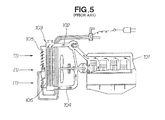
- Fig. 5 is a view explanatory of a basic construction of the vehicle engine cooling apparatus disclosed in JP S63-046245 B .
- the cooling water warmed by the heat of the engine 101 is directed into the radiator 103 via the cooling water passageway 102.
- the cooling water thus directed into the radiator 103 is cooled, together with the radiator 103, by air taken in from outside an engine room as indicated by arrow (1).
- the thus-cooled cooling water is returned to the engine 101 via a cooling water discharge passageway 104 to thereby cool the engine 101.
- the engine 101 has not been warmed enough and the temperature of the cooling water is still low immediately after activation of the engine 101. Thus, the temperature of the cooling water need not be lowered until the engine 101 is warmed enough. Therefore, in such a case, a shutter 105 provided in front of the radiator 103 is closed to prevent air (indicated by arrow (1) in the figure) from contacting the radiator 103. Thus, the engine 101 is prevented from being cooled, so that the engine 101 can be warmed promptly after the activation.
- the shutter 105 is opened, and thus, the radiator 103 can be subjected to air taken in from outside the engine room so that the temperature of the cooling water can be lowered.
- the vehicle is being run (or traveling) in a high-temperature environment for a long time. Under such a condition too, the cooling water for cooling the engine must be cooled sufficiently.
- a radiator core surface 106 is increased to allow the taken-in air to efficiently contact the radiator 103. Namely, the radiator core surface 106 is formed to have a great area so that it can sufficiently cool the cooling water even when the vehicle is being run in a high-temperature environment.
- the temperature of the cooling water tends to be rapidly cooled more than necessary if the vehicle is run with the shutter 105 kept opened under normal temperature. Once the cooling water drops below a predetermined temperature, the shutter 105 is closed, and thus, the temperature of the cooling water increases rapidly. Namely, with the vehicle engine cooling apparatus disclosed in JP S63-46245 B , the temperature of the cooling water frequently repeats increase and decrease and thus may become unstable. Stabilization of the cooling water temperature is desirable in that it can keep cooling the engine 101 in a stable manner.
- the present invention provides an improved vehicle engine cooling apparatus, which comprises: a radiator disposed within an engine room and in front of an engine for cooling engine cooling water; a shutter disposed in front of the radiator for adjusting an amount of cooling air to be directed toward the radiator, the shutter being disposed so as to cover a portion of a core surface of the radiator; and a baffle plate disposed behind of the remaining portion of the core surface, which is not covered with the shutter, for directing the air, having passed through the remaining portion, to outside the engine room.
- the engine cooling water can be not only sufficiently cooled by just the taken-in air being caused to contact the remaining portion of the radiator core surface but also prevented from being cooled excessively.
- the temperature of the cooling water can be stabilized, so that the engine can be cooled in a stable manner.
- the vehicle engine cooling apparatus further comprises an outside heat exchanger of a heat-pump type air conditioning device disposed between the shutter and the radiator, and the outside heat exchanger has its entire core surface covered with the shutter.
- the shutter need not be opened and thus is kept closed. With the shutter kept in the closed position like this, the air taken in from outside the engine room is prevented from flowing into the engine room, so that the engine room is not cooled.
- the outside heat exchanger uses warm air of the engine room.
- the present invention permits sufficient heating performance without the interior of the engine room being cooled.
- the vehicle engine cooling apparatus further comprises an air cooling heat exchanger disposed in front of the remaining portion of the core surface of the radiator.
- an air cooling heat exchanger disposed in front of the remaining portion of the core surface of the radiator.
- This vehicle engine cooling apparatus 10 which is provided for cooling an engine 12 disposed within an engine room 11 indicated by imaginary line, includes: a radiator 14 disposed in front of the engine 12 for cooling engine cooling water introduced thereinto via a cooling water introducing passageway 13; a cooling water discharge passageway 15 connected to the engine 12 for returning the cooling water, cooled by the radiator 14, to the engine 12; a fan 19 disposed in front of the engine 12 and behind a portion 18 of a core surface 17 of the radiator 14; and an air directing plate or baffle plate 22 disposed behind the remaining portion 21 of the core surface 17 of the radiator 14 for directing air, having passed through the remaining portion 21, to outside the engine room 11.
- the vehicle engine cooling apparatus 10 further includes: an outside heat exchanger 24 of a heat-pump type air conditioning device disposed in front of the one portion 18 of the core surface 17; a shutter 25 disposed in front of the outside heat exchanger 24 for adjusting an amount of air to be directed toward the radiator 14; an actuator 27 connected to the shutter 25 for opening and closing the shutter 25 under control of a control section 26; a water temperature sensor 28 disposed in the cooling water introducing passageway 13 for measuring the temperature of the cooling water introduced from the engine 12 and informing the control section 26 of the measured temperature; and an air cooling heat exchanger 29, such as an intercooler or ATF cooler, disposed in front of the remaining portion 21 of the core surface 17.
- an air cooling heat exchanger 29 such as an intercooler or ATF cooler
- At least the radiator 14, shutter 25 and other components 13, 15, 19, 21, 24, 28, 29 and33 are disposed within the engine room 11.
- the outside heat exchanger 24 of the heat-pump type air conditioning device is disposed between the shutter 25, and an entire core surface of the outside heat exchanger 24 is covered with the shutter 25.
- Dial 32 disposed in a vehicle compartment for switching between cooling and cooling states or modes is connected to the control section 26 for informing the control section 26 of which one of the cooling, heating and non-operating states the currently-set state of the cooling apparatus is.
- Motor 33 for driving the fan 19 is connected to the control section 26 to be controlled by the control section 26.
- the control section 26 causes the motor 33 to drive the fan 19 when the shutter 25 is in the opened position.
- the instant embodiment permits effective use of an empty space.
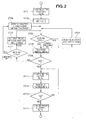
- Fig. 2 is a flow chart explanatory of operation of the embodiment of the vehicle engine cooling apparatus 10.
- the shutter 25 is closed, and the fan 19 is deactivated.
- a first setting temperature (e.g., 80 °C) T1 and a second setting temperature (e.g., 90 °C) T2higher than the first setting temperature T1 are set at step ST02.
- the control section 26 determines, at step ST03, as to whether or not the currently-set state of the cooling apparatus is the cooling state. If the dial 32 of Fig. 1 is currently at a "C" position, for example, the control section 26 determines that the currently-set state is the cooling state, so that control goes to step ST04, where the shutter 25 is opened while the fan 19 is turned on or activated. Then, as long as the vehicle is in the cooling state, the shutter 25 is kept in the opened position and the fan 19 is kept in the ON or activated state.
- step ST05 the control section 26 reads the water temperature Tw detected by the water temperature sensor 28. Then, the control section 26 determines, at step ST06, whether the read water temperature Tw is equal to or higher than the second setting temperature (e.g., 90 °C) T2.
- the second setting temperature e.g. 90 °C
- step ST06 With a NO determination at step ST06, i.e. if the read water temperature Tw is lower than the second temperature T2 as determined at step ST06, control branches to step ST07. If the device is in the heating state or mode at that time, the fan 19 is activated with the shutter 25 kept closed at step ST08, after which control reverts to step ST03. If the device is in the non-operating state at that time, the shutter 25 is kept in the closed position and the fan 19 is kept in the OFF state at step ST09, after which control reverts to step ST03. Activating the fan 19 with the shutter 25 kept closed in the heating state at step ST08 can achieve sufficient heating performance. On the other hand, keeping the fan 19 deactivated with the shutter 25 kept closed in the non-operating state at step ST09 can increase or raise the water temperature Tw.
- step ST06 With a YES determination at step ST06, i.e. if the water temperature Tw is equal to or higher than the setting temperature (e.g., 90 °C) T2 as determined at step ST06, control goes on to step ST11, where the shutter 25 is opened and the fan 19 is activated. Then, the control section 26 reads the water temperature Tw detected by the water temperature sensor 28, at step ST12.
- the setting temperature e.g. 90 °C
- step ST13 a determination is made as to whether the read water temperature Tw is equal to or lower than the first setting temperature (e.g., 80 °C) T1.
- the first setting temperature e.g. 80 °C
- control reverts to step ST11. Because the shutter 25 is opened and the fan 19 is activated at step ST11, the water temperature Tw can be lowered.
- step ST13 i.e. if the read water temperature Tw is equal to or lower than the first setting temperature T1 as determined at step ST13, the shutter 25 is closed and the fan 19 is deactivated or turned off at step ST14, after which the flow is brought to an end.
- Fig. 3 is a view explanatory of behavior of the embodiment of the vehicle engine cooling apparatus 10 when the shutter 25 is in the closed position and the fan 19 is in the OFF state.
- Air is taken in from outside the engine room 11 ( Fig. 1 ) as indicated by arrow (2), and a portion of the taken-in air having contacted the closed shutter 25 and another portion of the taken-in air having not contacted the closed shutter 25 flow toward the remaining portion 21 of the radiator core surface 17 as indicated by arrow (3).
- the air having passed through the remaining portion 21 is discharged out of the engine room 11 via the baffle plate 22, as indicated by arrow (4). In this way, the air can be prevented from flowing toward the engine 12, so that the engine 12 can be warmed promptly after activation of the engine 12.
- the cooling water is caused to flow through the radiator 14, so that the cooling water flowing through the radiator 14 is cooled by the air passing through the remaining portion 21.
- the cooling water can be not only sufficiently cooled by just the taken-in air being caused to contact the remaining portion 21 of the radiator core surface 17 but also prevented from being cooled excessively.
- the temperature of the cooling water can be stabilized, so that the engine 12 can be cooled in a stable manner.
- the shutter 25 need not be opened and thus is kept closed. With the shutter 25 kept in the closed position like this, the air taken in from outside the engine room 11 is prevented from flowing into the engine room 11, so that the engine room 11 is not cooled.
- the outside heat exchanger 24 uses warm air of the engine room 11.
- Fig. 4 is a view explanatory of behavior of the embodiment of the vehicle engine cooling apparatus 10 when the shutter 25 is in the opened position and the fan 19 is in the ON or activated state.
- Air is taken in from outside the engine room 11 as indicated by arrow (5), and a portion of the taken-in air passes through the shutter 25 and then passes through the portion 18 of the core surface 17 as indicated by arrow (6).
- the shutter 25 is opened to cause a large amount of air to contact the radiator 14 to thereby cool the cooling water.
- the instant embodiment can reduce the amount of air to be taken into the engine room 11 and thereby enhance the aerodynamic performance of the vehicle.
- an upper portion of the radiator core surface 17 is provided as the one portion of the radiator core surface 17 covered with the shutter 25.
- any other desired portion, such as a lower portion, right portion or left portion, of the radiator core surface 17 may be provided as the one portion of the radiator core surface 17 covered with the shutter 25.
- the vehicle engine cooling apparatus of the present invention is well suited for application to four-wheeled vehicles.
- Radiator 14 is provided within an engine room 11 and in front of an engine 12 for cooling engine cooling water.
- Shutter 25 is provided in front of the radiator and covers a portion 18 of a core surface 17 of the radiator 14 for adjusting an amount of cooling air to be directed toward the radiator.
- Baffle plate 22, is provided behind of the remaining portion 21 of the core surface, which is not covered with the shutter 25 for directing the air, having passed through the remaining portion 21 to outside the engine room.
Landscapes
- Engineering & Computer Science (AREA)
- Chemical & Material Sciences (AREA)
- Combustion & Propulsion (AREA)
- Mechanical Engineering (AREA)
- General Engineering & Computer Science (AREA)
- Transportation (AREA)
- Cooling, Air Intake And Gas Exhaust, And Fuel Tank Arrangements In Propulsion Units (AREA)
Abstract
Description
- The present invention relates to apparatus for cooling vehicle engines.
- In automotive vehicles, a radiator is provided in front of an engine, in order to cool cooling water warmed by the engine. The radiator is connected to the engine via a cooling water passageway so that the cooling water flows from the engine into the radiator. The radiator is cooled by air introduced thereinto from outside the vehicle, and thus, the temperature of the cooling water flowing within the radiator is also lowered. Various cooling apparatus for cooling engine cooling water have been proposed, one example of which is disclosed in Japanese Patent Publication No.
SHO-63-46245 JP S63-046245 B -
Fig. 5 is a view explanatory of a basic construction of the vehicle engine cooling apparatus disclosed inJP S63-046245 B engine 101 is directed into theradiator 103 via thecooling water passageway 102. The cooling water thus directed into theradiator 103 is cooled, together with theradiator 103, by air taken in from outside an engine room as indicated by arrow (1). The thus-cooled cooling water is returned to theengine 101 via a coolingwater discharge passageway 104 to thereby cool theengine 101. - In such a vehicle engine cooling apparatus, the
engine 101 has not been warmed enough and the temperature of the cooling water is still low immediately after activation of theengine 101. Thus, the temperature of the cooling water need not be lowered until theengine 101 is warmed enough. Therefore, in such a case, ashutter 105 provided in front of theradiator 103 is closed to prevent air (indicated by arrow (1) in the figure) from contacting theradiator 103. Thus, theengine 101 is prevented from being cooled, so that theengine 101 can be warmed promptly after the activation. Once the temperature of theengine 101 exceeds a predetermined temperature and a need arises to lower the temperature of the cooling water, theshutter 105 is opened, and thus, theradiator 103 can be subjected to air taken in from outside the engine room so that the temperature of the cooling water can be lowered. - Sometimes, the vehicle is being run (or traveling) in a high-temperature environment for a long time. Under such a condition too, the cooling water for cooling the engine must be cooled sufficiently. For that purpose, a
radiator core surface 106 is increased to allow the taken-in air to efficiently contact theradiator 103. Namely, theradiator core surface 106 is formed to have a great area so that it can sufficiently cool the cooling water even when the vehicle is being run in a high-temperature environment. - Because the
radiator core surface 106 has a great area, the temperature of the cooling water tends to be rapidly cooled more than necessary if the vehicle is run with theshutter 105 kept opened under normal temperature. Once the cooling water drops below a predetermined temperature, theshutter 105 is closed, and thus, the temperature of the cooling water increases rapidly. Namely, with the vehicle engine cooling apparatus disclosed inJP S63-46245 B engine 101 in a stable manner. - In view of the foregoing prior art problems, it is an object of the present invention to provide an improved cooling apparatus which can cool a vehicle engine in a stable manner.
- In order to accomplish the above-mentioned object, the present invention provides an improved vehicle engine cooling apparatus, which comprises: a radiator disposed within an engine room and in front of an engine for cooling engine cooling water; a shutter disposed in front of the radiator for adjusting an amount of cooling air to be directed toward the radiator, the shutter being disposed so as to cover a portion of a core surface of the radiator; and a baffle plate disposed behind of the remaining portion of the core surface, which is not covered with the shutter, for directing the air, having passed through the remaining portion, to outside the engine room.
- With the shutter in the closed position, air taken in from outside the engine room passes through the remaining portion of the core surface which is not covered with the shutter. Thus, when the vehicle is being run (or traveling) in a normal temperature environment, the engine cooling water can be not only sufficiently cooled by just the taken-in air being caused to contact the remaining portion of the radiator core surface but also prevented from being cooled excessively. Thus, the temperature of the cooling water can be stabilized, so that the engine can be cooled in a stable manner.
- Preferably, the vehicle engine cooling apparatus further comprises an outside heat exchanger of a heat-pump type air conditioning device disposed between the shutter and the radiator, and the outside heat exchanger has its entire core surface covered with the shutter. When the vehicle is being run in a low temperature environment, the shutter need not be opened and thus is kept closed. With the shutter kept in the closed position like this, the air taken in from outside the engine room is prevented from flowing into the engine room, so that the engine room is not cooled. The outside heat exchanger uses warm air of the engine room. Thus, when the external temperature is low and heating is required, the present invention permits sufficient heating performance without the interior of the engine room being cooled.
- Preferably, the vehicle engine cooling apparatus further comprises an air cooling heat exchanger disposed in front of the remaining portion of the core surface of the radiator. In this way, the present invention permits effective use of an empty space.
- The following will describe embodiments of the present invention, but it should be appreciated that the present invention is not limited to the described embodiments and various modifications of the invention are possible without departing from the basic principles. The scope of the present invention is therefore to be determined solely by the appended claims.
- Certain preferred embodiments of the present invention will be described in detail below, by way of example only, with reference to the accompanying drawings, in which:
-
Fig. 1 is a view showing a vehicle engine cooling apparatus according to an embodiment of the present invention; -
Fig. 2 is a flow chart explanatory of operation of the embodiment of the vehicle engine cooling apparatus; -
Fig. 3 is a view explanatory of behavior of the embodiment of the vehicle engine cooling apparatus when a shutter is in a closed position and a fan is in an OFF or non-activated state; -
Fig. 4 is explanatory of behavior of the embodiment of the vehicle engine cooling apparatus when the shutter is in an opened position and the fan is in an ON or activated state; and -
Fig. 5 is a view illustrating a basic construction of a conventional vehicle engine cooling apparatus. - Reference is now made to
Fig. 1 showing a vehicleengine cooling apparatus 10 according to an embodiment of the present invention. This vehicleengine cooling apparatus 10, which is provided for cooling anengine 12 disposed within an engine room 11 indicated by imaginary line, includes: aradiator 14 disposed in front of theengine 12 for cooling engine cooling water introduced thereinto via a coolingwater introducing passageway 13; a coolingwater discharge passageway 15 connected to theengine 12 for returning the cooling water, cooled by theradiator 14, to theengine 12; afan 19 disposed in front of theengine 12 and behind aportion 18 of acore surface 17 of theradiator 14; and an air directing plate orbaffle plate 22 disposed behind theremaining portion 21 of thecore surface 17 of theradiator 14 for directing air, having passed through theremaining portion 21, to outside the engine room 11. The vehicleengine cooling apparatus 10 further includes: anoutside heat exchanger 24 of a heat-pump type air conditioning device disposed in front of the oneportion 18 of thecore surface 17; ashutter 25 disposed in front of theoutside heat exchanger 24 for adjusting an amount of air to be directed toward theradiator 14; anactuator 27 connected to theshutter 25 for opening and closing theshutter 25 under control of acontrol section 26; awater temperature sensor 28 disposed in the coolingwater introducing passageway 13 for measuring the temperature of the cooling water introduced from theengine 12 and informing thecontrol section 26 of the measured temperature; and an aircooling heat exchanger 29, such as an intercooler or ATF cooler, disposed in front of theremaining portion 21 of thecore surface 17. - Of the above-mentioned component parts, at least the
radiator 14,shutter 25 andother components outside heat exchanger 24 of the heat-pump type air conditioning device is disposed between theshutter 25, and an entire core surface of theoutside heat exchanger 24 is covered with theshutter 25. -
Dial 32 disposed in a vehicle compartment for switching between cooling and cooling states or modes is connected to thecontrol section 26 for informing thecontrol section 26 of which one of the cooling, heating and non-operating states the currently-set state of the cooling apparatus is. -
Motor 33 for driving thefan 19 is connected to thecontrol section 26 to be controlled by thecontrol section 26. Thecontrol section 26 causes themotor 33 to drive thefan 19 when theshutter 25 is in the opened position. - With the air
cooling heat exchanger 29 disposed in front of theremaining portion 21, the instant embodiment permits effective use of an empty space. - The following paragraphs describe behavior of the vehicle engine cooling apparatus constructed in the aforementioned manner.
-
Fig. 2 is a flow chart explanatory of operation of the embodiment of the vehicleengine cooling apparatus 10. At an initialization step ST01, theshutter 25 is closed, and thefan 19 is deactivated. - Then, a first setting temperature (e.g., 80 °C) T1 and a second setting temperature (e.g., 90 °C) T2higher than the first setting temperature T1 are set at step ST02. Next, the
control section 26 determines, at step ST03, as to whether or not the currently-set state of the cooling apparatus is the cooling state. If thedial 32 ofFig. 1 is currently at a "C" position, for example, thecontrol section 26 determines that the currently-set state is the cooling state, so that control goes to step ST04, where theshutter 25 is opened while thefan 19 is turned on or activated. Then, as long as the vehicle is in the cooling state, theshutter 25 is kept in the opened position and thefan 19 is kept in the ON or activated state. - If the currently-set state is not the cooling state as determined at step ST03, i.e. if the currently-set state is the heating state or non-operating state, control proceeds to step ST05, where the
control section 26 reads the water temperature Tw detected by thewater temperature sensor 28. Then, thecontrol section 26 determines, at step ST06, whether the read water temperature Tw is equal to or higher than the second setting temperature (e.g., 90 °C) T2. - With a NO determination at step ST06, i.e. if the read water temperature Tw is lower than the second temperature T2 as determined at step ST06, control branches to step ST07. If the device is in the heating state or mode at that time, the
fan 19 is activated with theshutter 25 kept closed at step ST08, after which control reverts to step ST03. If the device is in the non-operating state at that time, theshutter 25 is kept in the closed position and thefan 19 is kept in the OFF state at step ST09, after which control reverts to step ST03. Activating thefan 19 with theshutter 25 kept closed in the heating state at step ST08 can achieve sufficient heating performance. On the other hand, keeping thefan 19 deactivated with theshutter 25 kept closed in the non-operating state at step ST09 can increase or raise the water temperature Tw. - With a YES determination at step ST06, i.e. if the water temperature Tw is equal to or higher than the setting temperature (e.g., 90 °C) T2 as determined at step ST06, control goes on to step ST11, where the
shutter 25 is opened and thefan 19 is activated. Then, thecontrol section 26 reads the water temperature Tw detected by thewater temperature sensor 28, at step ST12. - Then, at step ST13, a determination is made as to whether the read water temperature Tw is equal to or lower than the first setting temperature (e.g., 80 °C) T1. With a NO determination at step ST13, i.e. if the water temperature Tw is higher than the first setting temperature T1 as determined at step ST13, control reverts to step ST11. Because the
shutter 25 is opened and thefan 19 is activated at step ST11, the water temperature Tw can be lowered. - On the other hand, with a YES determination at step ST13, i.e. if the read water temperature Tw is equal to or lower than the first setting temperature T1 as determined at step ST13, the
shutter 25 is closed and thefan 19 is deactivated or turned off at step ST14, after which the flow is brought to an end. - The following describe behavior of the embodiment of the vehicle
engine cooling apparatus 10 when theshutter 25 is in the closed position and thefan 19 is in the OFF or non-activated state.Fig. 3 is a view explanatory of behavior of the embodiment of the vehicleengine cooling apparatus 10 when theshutter 25 is in the closed position and thefan 19 is in the OFF state. Air is taken in from outside the engine room 11 (Fig. 1 ) as indicated by arrow (2), and a portion of the taken-in air having contacted theclosed shutter 25 and another portion of the taken-in air having not contacted theclosed shutter 25 flow toward the remainingportion 21 of theradiator core surface 17 as indicated by arrow (3). The air having passed through the remainingportion 21 is discharged out of the engine room 11 via thebaffle plate 22, as indicated by arrow (4). In this way, the air can be prevented from flowing toward theengine 12, so that theengine 12 can be warmed promptly after activation of theengine 12. - Once the
engine 12 is warmed, the cooling water is caused to flow through theradiator 14, so that the cooling water flowing through theradiator 14 is cooled by the air passing through the remainingportion 21. - With the
shutter 25 kept in the closed position, the air taken in from outside the engine room 11 passes through the remainingportion 21 of thecore surface 17 which is not covered with theshutter 25. Thus, when the vehicle is being run (or traveling) in a normal temperature environment, the cooling water can be not only sufficiently cooled by just the taken-in air being caused to contact the remainingportion 21 of theradiator core surface 17 but also prevented from being cooled excessively. Thus, the temperature of the cooling water can be stabilized, so that theengine 12 can be cooled in a stable manner. - Namely, when the vehicle is being run in a low temperature environment, the
shutter 25 need not be opened and thus is kept closed. With theshutter 25 kept in the closed position like this, the air taken in from outside the engine room 11 is prevented from flowing into the engine room 11, so that the engine room 11 is not cooled. Theoutside heat exchanger 24 uses warm air of the engine room 11. Thus, when the external temperature is low and heating is required, the instant embodiment permits sufficient heating performance without the interior of the engine room being cooled. - The following describe behavior of the embodiment of the vehicle
engine cooling apparatus 10 when theshutter 25 is in the opened position and thefan 19 is in the ON or activated state.Fig. 4 is a view explanatory of behavior of the embodiment of the vehicleengine cooling apparatus 10 when theshutter 25 is in the opened position and thefan 19 is in the ON or activated state. Air is taken in from outside the engine room 11 as indicated by arrow (5), and a portion of the taken-in air passes through theshutter 25 and then passes through theportion 18 of thecore surface 17 as indicated by arrow (6). - Another portion of the taken-in air, which has not passed through the
shutter 25, passes through the remainingportion 21 of thecore surface 17 and then discharged out of the engine room 11 as indicated by arrow (7). - Namely, when the vehicle is being run in a high temperature environment for a long time, there is a need to cause a large amount of air to contact the
radiator core surface 17, in order to cool the cooling water. Thus, in this case, theshutter 25 is opened to cause a large amount of air to contact theradiator 14 to thereby cool the cooling water. - When the
shutter 25 is open as well, the air having passed through the remainingportion 21 of theradiator core surface 17 is discharged out of the engine room via thebaffle plate 22. Namely, with thebaffle plate 22, the instant embodiment can reduce the amount of air to be taken into the engine room 11 and thereby enhance the aerodynamic performance of the vehicle. - In the above-described embodiment, an upper portion of the
radiator core surface 17 is provided as the one portion of theradiator core surface 17 covered with theshutter 25. Alternatively, any other desired portion, such as a lower portion, right portion or left portion, of theradiator core surface 17 may be provided as the one portion of theradiator core surface 17 covered with theshutter 25. - The vehicle engine cooling apparatus of the present invention is well suited for application to four-wheeled vehicles.
-
Radiator 14 is provided within an engine room 11 and in front of anengine 12 for cooling engine cooling water.Shutter 25 is provided in front of the radiator and covers aportion 18 of acore surface 17 of theradiator 14 for adjusting an amount of cooling air to be directed toward the radiator.Baffle plate 22, is provided behind of the remainingportion 21 of the core surface, which is not covered with theshutter 25 for directing the air, having passed through the remainingportion 21 to outside the engine room.
Claims (3)
- A vehicle engine cooling apparatus (10) comprising:a radiator (14) disposed within an engine room (11) and in front of an engine (12) for cooling engine cooling water;a shutter (25) disposed in front of the radiator (14) for adjusting an amount of cooling air to be directed toward the radiator, the shutter being disposed so as to cover a portion (18) of a core surface (17) of the radiator; anda baffle plate (22) disposed behind of a remaining portion (21) of the core surface, which is not covered with the shutter (25), for directing the air, having passed through the remaining portion (21), to outside the engine room.
- The vehicle engine cooling apparatus of claim 1, further comprising an outside heat exchanger (24) of a heat-pump type air conditioning device disposed between the shutter (25) and the radiator (14), wherein the outside heat exchanger (24) has an entire core surface thereof covered with the shutter (25).
- The vehicle engine cooling apparatus of claim 1 or 2, further comprising an air cooling heat exchanger (29) disposed in front of the remaining portion (21) of the core surface of the radiator.
Applications Claiming Priority (1)
| Application Number | Priority Date | Filing Date | Title |
|---|---|---|---|
| JP2008257114A JP4909972B2 (en) | 2008-10-02 | 2008-10-02 | Cooling device for vehicle engine |
Publications (2)
| Publication Number | Publication Date |
|---|---|
| EP2172631A1 true EP2172631A1 (en) | 2010-04-07 |
| EP2172631B1 EP2172631B1 (en) | 2011-12-14 |
Family
ID=41327328
Family Applications (1)
| Application Number | Title | Priority Date | Filing Date |
|---|---|---|---|
| EP09170958A Not-in-force EP2172631B1 (en) | 2008-10-02 | 2009-09-22 | Vehicle engine cooling apparatus |
Country Status (5)
| Country | Link |
|---|---|
| US (1) | US8281754B2 (en) |
| EP (1) | EP2172631B1 (en) |
| JP (1) | JP4909972B2 (en) |
| CN (1) | CN101713324B (en) |
| AT (1) | ATE537342T1 (en) |
Cited By (1)
| Publication number | Priority date | Publication date | Assignee | Title |
|---|---|---|---|---|
| CN102248888A (en) * | 2010-05-17 | 2011-11-23 | 通用汽车环球科技运作有限责任公司 | Grille airflow shutter system with discrete shutter control |
Families Citing this family (61)
| Publication number | Priority date | Publication date | Assignee | Title |
|---|---|---|---|---|
| JP4667141B2 (en) * | 2005-07-05 | 2011-04-06 | ヤンマー株式会社 | Swivel work vehicle |
| CN1952602A (en) * | 2005-10-18 | 2007-04-25 | 国际商业机器公司 | Method and apparatus for determining the location of a user in an area |
| FR2950574B1 (en) * | 2009-09-29 | 2012-03-23 | Valeo Systemes Thermiques | THERMAL EXCHANGE BLOCK FOR MOTOR VEHICLE |
| JP5429551B2 (en) * | 2009-11-19 | 2014-02-26 | アイシン精機株式会社 | Vehicle grill control mechanism |
| US8646552B2 (en) | 2010-07-21 | 2014-02-11 | Shape Corp. | Integrated energy absorber and air flow management structure |
| US20120090906A1 (en) * | 2010-10-14 | 2012-04-19 | Gm Global Technology Operations, Inc. | Ventilation assembly for a front exterior of a vehicle |
| US20120097464A1 (en) * | 2010-10-22 | 2012-04-26 | Gm Global Technology Operations, Inc. | Control of a shutter via bi-directional communication using a single wire |
| US20120097465A1 (en) * | 2010-10-22 | 2012-04-26 | Gm Global Technology Operations, Inc. | System and method for controlling a shutter in a vehicle via a cooling fan duty-cycle |
| US8443921B2 (en) * | 2010-11-09 | 2013-05-21 | GM Global Technology Operations LLC | System and method for increasing operating efficiency of a powertrain by controlling an aero shutter |
| US8561738B2 (en) * | 2010-11-30 | 2013-10-22 | GM Global Technology Operations LLC | Compound shutter system with independent and non-sequential operation |
| US8479852B2 (en) | 2011-02-07 | 2013-07-09 | Honda Motor Co., Ltd. | Vehicle component air flow ducting system |
| JP5411186B2 (en) | 2011-03-18 | 2014-02-12 | アイシン精機株式会社 | Grill shutter control device |
| DE102011015126B4 (en) * | 2011-03-25 | 2014-09-25 | Airbus Operations Gmbh | Aircraft tail area with a cooling system installed in the aircraft rear area |
| US20120270490A1 (en) * | 2011-04-21 | 2012-10-25 | GM Global Technology Operations LLC | System and method of shutter control |
| US9121335B2 (en) * | 2011-05-13 | 2015-09-01 | Ford Global Technologies, Llc | System and method for an engine comprising a liquid cooling system and oil supply |
| US8469128B2 (en) * | 2011-06-13 | 2013-06-25 | GM Global Technology Operations LLC | Variable-bias shutter |
| US8892314B2 (en) * | 2011-06-15 | 2014-11-18 | GM Global Technology Operations LLC | Rejection of under-hood airflow |
| US8631889B2 (en) * | 2011-06-20 | 2014-01-21 | David Begleiter | Combined condensation radiator fan module and brake cooling duct shutter system |
| US8667931B2 (en) | 2011-08-09 | 2014-03-11 | Ford Global Technologies, Llc | Control method for a vehicle air intake system |
| JP5807486B2 (en) * | 2011-09-28 | 2015-11-10 | アイシン精機株式会社 | Grill shutter device |
| US20130081888A1 (en) * | 2011-09-30 | 2013-04-04 | GM Global Technology Operations LLC | Reconfigurable baseline opening for under-hood airflow |
| DE102012209370A1 (en) * | 2012-06-04 | 2013-12-05 | Robert Bosch Gmbh | Method for lowering the air temperature of an engine compartment of a vehicle |
| US9657632B2 (en) | 2012-08-01 | 2017-05-23 | GM Global Technology Operations LLC | Method and apparatus for remote torque control of an aerodynamic air shutter mechanism |
| US9879589B2 (en) | 2012-08-06 | 2018-01-30 | GM Global Technology Operations LLC | Initialization sequence for a vehicle grille shutter |
| US9512774B2 (en) * | 2012-08-23 | 2016-12-06 | Honda Motor Co., Ltd. | Cooling device for use with engines |
| JP6036169B2 (en) * | 2012-10-30 | 2016-11-30 | いすゞ自動車株式会社 | Vehicle cooling system |
| DE102013002362A1 (en) * | 2013-02-08 | 2014-08-28 | Daimler Ag | Method for operating a radiator grill arrangement of a vehicle |
| JP2014189077A (en) * | 2013-03-26 | 2014-10-06 | Fuji Heavy Ind Ltd | Hybrid vehicle |
| US20150041229A1 (en) * | 2013-08-08 | 2015-02-12 | Honda Motor Co., Ltd. | Front end arrangement with active radiator damper and active radiator control method |
| US9751377B2 (en) | 2013-08-15 | 2017-09-05 | Deere & Company | Multi-unit cooling system with dynamic baffle |
| CN103452639B (en) * | 2013-09-18 | 2016-08-17 | 北京汽车股份有限公司 | A kind of engine radiator, electromotor and vehicle |
| CN104832268A (en) * | 2014-06-17 | 2015-08-12 | 北汽福田汽车股份有限公司 | Cooling device for engine and engine cooling system and method |
| KR102026103B1 (en) * | 2014-09-05 | 2019-09-27 | 한온시스템 주식회사 | Cooling module |
| US10252611B2 (en) * | 2015-01-22 | 2019-04-09 | Ford Global Technologies, Llc | Active seal arrangement for use with vehicle condensers |
| DE102015207442A1 (en) * | 2015-04-23 | 2016-10-27 | Siemens Aktiengesellschaft | Vehicle with a vehicle component to be cooled |
| DE102015109698B4 (en) * | 2015-06-17 | 2021-06-24 | Hbpo Gmbh | Cooling system for a vehicle |
| US9840144B2 (en) * | 2015-08-19 | 2017-12-12 | Mazda Motor Corporation | Front air-rectifying structure of automotive vehicle |
| US9828044B2 (en) * | 2015-09-25 | 2017-11-28 | GM Global Technology Operations LLC | Feedback control of vehicle aerodynamics |
| JP6566817B2 (en) * | 2015-09-29 | 2019-08-28 | 株式会社クボタ | Work vehicle |
| US20180370348A1 (en) * | 2015-12-09 | 2018-12-27 | Denso Corporation | Cooling device |
| JP6382787B2 (en) * | 2015-12-11 | 2018-08-29 | カルソニックカンセイ株式会社 | Cooling system |
| JP6382788B2 (en) * | 2015-12-11 | 2018-08-29 | カルソニックカンセイ株式会社 | Cooling system |
| JP6386992B2 (en) * | 2015-12-11 | 2018-09-05 | カルソニックカンセイ株式会社 | Cooling system |
| US10336180B2 (en) * | 2016-06-17 | 2019-07-02 | Ford Global Technologies, Llc | Method and system for a vehicle cooling system |
| DE102016218391A1 (en) * | 2016-09-23 | 2018-03-29 | Röchling Automotive SE & Co. KG | Magnetic field-based operating state detection of air dampers |
| KR101846722B1 (en) * | 2016-10-20 | 2018-04-09 | 현대자동차주식회사 | Cooling system for vehicle and control method thereof |
| JP6658713B2 (en) * | 2016-12-28 | 2020-03-04 | 株式会社デンソー | Control module |
| WO2018123325A1 (en) * | 2016-12-28 | 2018-07-05 | 株式会社デンソー | Control module |
| US10457136B2 (en) | 2017-03-30 | 2019-10-29 | Gdc, Inc. | Single shot injection molded article |
| US10464412B2 (en) * | 2017-06-19 | 2019-11-05 | Ford Global Technologies, Llc | Methods and system for diagnosing a position of active grille shutters of a vehicle |
| US11512623B2 (en) * | 2017-07-17 | 2022-11-29 | Kohler Co. | Apparatus for controlling cooling airflow to an intenral combustion engine, and engines and methods utilizing the same |
| US10647175B2 (en) * | 2017-11-14 | 2020-05-12 | Cummins Inc. | Dynamic fan speed control for aerodynamic drag reduction |
| US10813286B2 (en) * | 2017-11-15 | 2020-10-27 | Cnh Industrial America Llc | System and method for adjusting the flow orientation of an air flow exhausted from an agricultural harvester |
| DE102018200936A1 (en) * | 2018-01-22 | 2019-07-25 | Ford Global Technologies, Llc | Device and method for controlling a temperature of a vehicle component by means of air guiding means |
| CN108437779B (en) * | 2018-05-17 | 2023-06-20 | 北京汽车集团有限公司 | Engine cooling system, vehicle and engine cooling method |
| CN109398072B (en) * | 2018-12-05 | 2024-05-24 | 江苏理工学院 | Smart grille |
| JP7182657B2 (en) * | 2021-04-28 | 2022-12-02 | 本田技研工業株式会社 | vehicle |
| US11598244B2 (en) * | 2021-07-30 | 2023-03-07 | Cnh Industrial America Llc | Active baffling for cooling systems |
| CN115214300A (en) * | 2022-04-06 | 2022-10-21 | 长城汽车股份有限公司 | Vehicle cooling module, system and control method thereof, and vehicle |
| CN114714892B (en) * | 2022-04-15 | 2025-01-28 | 北京航天发射技术研究所 | Intelligent power unit compartment |
| CN114961964B (en) * | 2022-06-02 | 2024-01-05 | 中国第一汽车股份有限公司 | Control method and device for vehicle cooling system, storage medium and processor |
Citations (4)
| Publication number | Priority date | Publication date | Assignee | Title |
|---|---|---|---|---|
| GB2131150A (en) * | 1982-10-08 | 1984-06-13 | Stephen Hugh Phillips | Vehicle radiator grille with shuttered operation |
| JPS6346245B2 (en) | 1982-11-30 | 1988-09-14 | Mikuni Kogyo Kk | |
| JP2002225573A (en) * | 2000-10-03 | 2002-08-14 | Denso Corp | Vehicle cooling system |
| EP1760287A1 (en) * | 2005-08-29 | 2007-03-07 | Ford Global Technologies, LLC | An improved cooling system for a motor vehicle |
Family Cites Families (31)
| Publication number | Priority date | Publication date | Assignee | Title |
|---|---|---|---|---|
| US1390724A (en) * | 1917-04-05 | 1921-09-13 | George J Rumens | Cooling apparatus for motor-vehicles |
| US4476820A (en) * | 1981-07-06 | 1984-10-16 | John Nixon | Engine compartment structure |
| JPS6036716A (en) * | 1983-08-08 | 1985-02-25 | Nissan Motor Co Ltd | Apparatus for preventing over-cooling of engine used for driving vehicle |
| DE8427839U1 (en) * | 1984-09-21 | 1985-02-07 | Dr.Ing.H.C. F. Porsche Ag, 7000 Stuttgart | MOTOR VEHICLE WITH A BOW-SIDED RADIATOR ARRANGEMENT, INCLUDING FRONT AIR INLETS AND SIDE VENTILATION OPENINGS |
| DE3446950C1 (en) * | 1984-12-21 | 1986-05-22 | Bayerische Motoren Werke AG, 8000 München | Control device for the cooling air of air-liquid-cooled internal combustion engines, in particular of motor vehicles |
| DE3625375A1 (en) * | 1986-07-26 | 1988-02-04 | Porsche Ag | COOLING FLAP AND BLOWER CONTROL FOR MOTOR VEHICLES |
| JPH0619978Y2 (en) * | 1988-02-09 | 1994-05-25 | 日産自動車株式会社 | Rotating radiator |
| JPH01129589U (en) * | 1988-02-20 | 1989-09-04 | ||
| DE3825071C1 (en) * | 1988-07-23 | 1989-10-05 | Daimler-Benz Aktiengesellschaft, 7000 Stuttgart, De | |
| DE3917108C1 (en) * | 1989-05-26 | 1990-08-02 | Daimler-Benz Aktiengesellschaft, 7000 Stuttgart, De | |
| DE3933199C1 (en) * | 1989-10-05 | 1990-12-13 | Mercedes-Benz Aktiengesellschaft, 7000 Stuttgart, De | |
| JP2800346B2 (en) * | 1990-02-06 | 1998-09-21 | 株式会社デンソー | Cooling system for water-cooled internal combustion engine for vehicles |
| JP2924171B2 (en) * | 1990-11-23 | 1999-07-26 | 株式会社デンソー | Cooling system for water-cooled internal combustion engine for vehicles |
| AU642787B2 (en) * | 1990-11-23 | 1993-10-28 | Nippondenso Co. Ltd. | Cooling system for a water cooled internal combustion engine for vehicle having an airconditioning apparatus |
| JP2894033B2 (en) * | 1991-08-16 | 1999-05-24 | 株式会社デンソー | Cooling system for internal combustion engine for vehicles |
| JP3156801B2 (en) * | 1991-10-17 | 2001-04-16 | 本田技研工業株式会社 | Automotive air conditioners |
| JP3079735B2 (en) * | 1992-01-29 | 2000-08-21 | 株式会社デンソー | Cooling system for water-cooled internal combustion engine for vehicles |
| JP3340161B2 (en) * | 1992-12-03 | 2002-11-05 | 株式会社日立製作所 | Cooling air conditioner for electric vehicles |
| US5566745A (en) * | 1993-05-10 | 1996-10-22 | General Electric Company | Shuttered radiator system with control |
| US5775450A (en) * | 1996-05-06 | 1998-07-07 | General Motors Corporation | Vehicle underhood component cooling system |
| JP3952532B2 (en) | 1997-03-31 | 2007-08-01 | マツダ株式会社 | In-vehicle electronic device apparatus and electronic device assembly |
| DE19910651A1 (en) * | 1998-03-13 | 1999-09-16 | Denso Corp | Engine cooling device for vehicle |
| JP4306071B2 (en) * | 1999-03-11 | 2009-07-29 | 株式会社デンソー | Vehicle cooling system |
| DE10030355A1 (en) * | 2000-06-21 | 2002-01-03 | Modine Mfg Co | Cooling device for internal combustion engines |
| US6390217B1 (en) * | 2001-04-02 | 2002-05-21 | Delphi Technologies, Inc. | Vehicle front end air control |
| US7766111B2 (en) * | 2004-10-29 | 2010-08-03 | Daimler Trucks North America Llc | Selective closing of at least one vehicle opening at a front portion of a vehicle |
| DE102005044559A1 (en) * | 2005-09-17 | 2007-03-29 | Behr Gmbh & Co. Kg | Arrangement for cooling an internal combustion engine of a motor vehicle, in particular cooling module |
| JP2007099194A (en) * | 2005-10-07 | 2007-04-19 | Toyota Motor Corp | Ventilation structure of vehicle cooling system |
| US7757643B2 (en) * | 2006-01-12 | 2010-07-20 | Behr Gmbh & Co. Kg | Device for regulating an air flow for engine cooling |
| JP4853641B2 (en) * | 2006-11-24 | 2012-01-11 | トヨタ自動車株式会社 | Fuel cell vehicle |
| JP2008221997A (en) * | 2007-03-12 | 2008-09-25 | Toyota Motor Corp | Air conditioner for vehicles |
-
2008
- 2008-10-02 JP JP2008257114A patent/JP4909972B2/en not_active Expired - Fee Related
-
2009
- 2009-09-22 AT AT09170958T patent/ATE537342T1/en active
- 2009-09-22 EP EP09170958A patent/EP2172631B1/en not_active Not-in-force
- 2009-09-29 CN CN200910178096XA patent/CN101713324B/en not_active Expired - Fee Related
- 2009-09-30 US US12/570,557 patent/US8281754B2/en not_active Expired - Fee Related
Patent Citations (4)
| Publication number | Priority date | Publication date | Assignee | Title |
|---|---|---|---|---|
| GB2131150A (en) * | 1982-10-08 | 1984-06-13 | Stephen Hugh Phillips | Vehicle radiator grille with shuttered operation |
| JPS6346245B2 (en) | 1982-11-30 | 1988-09-14 | Mikuni Kogyo Kk | |
| JP2002225573A (en) * | 2000-10-03 | 2002-08-14 | Denso Corp | Vehicle cooling system |
| EP1760287A1 (en) * | 2005-08-29 | 2007-03-07 | Ford Global Technologies, LLC | An improved cooling system for a motor vehicle |
Cited By (1)
| Publication number | Priority date | Publication date | Assignee | Title |
|---|---|---|---|---|
| CN102248888A (en) * | 2010-05-17 | 2011-11-23 | 通用汽车环球科技运作有限责任公司 | Grille airflow shutter system with discrete shutter control |
Also Published As
| Publication number | Publication date |
|---|---|
| JP4909972B2 (en) | 2012-04-04 |
| US20100083917A1 (en) | 2010-04-08 |
| ATE537342T1 (en) | 2011-12-15 |
| EP2172631B1 (en) | 2011-12-14 |
| CN101713324A (en) | 2010-05-26 |
| CN101713324B (en) | 2012-01-11 |
| JP2010084723A (en) | 2010-04-15 |
| US8281754B2 (en) | 2012-10-09 |
Similar Documents
| Publication | Publication Date | Title |
|---|---|---|
| EP2172631B1 (en) | Vehicle engine cooling apparatus | |
| US8833313B2 (en) | Grille airflow shutter system with discrete shutter control | |
| US8091516B2 (en) | Cooling device | |
| US8645028B2 (en) | Grille control mechanism for vehicle | |
| US8662569B2 (en) | Dual torque active grille shutter for snow and ice | |
| US6588380B2 (en) | Cooling system for a motor vehicle comprising a closing unit for the cooling airflow | |
| EP1992508B1 (en) | Vehicle air conditioning device | |
| KR101822690B1 (en) | Adjustment device for air inlet, method for adjusting an air inlet with an adjustment device, motor vehicle provided with an air inlet having an adjustment device | |
| JP5775536B2 (en) | Freezing detection device for vehicle active shutter | |
| US11181034B2 (en) | Cooling system | |
| US20100236503A1 (en) | Cooling air supply apparatus for an internal combustion engine having an emergency operation device | |
| US20100051712A1 (en) | Variable Air Intake Opening for a Vehicle | |
| KR101567733B1 (en) | External type active air flap apparatus for vehicle | |
| CN110067634A (en) | Use the device and method of air guide element control vehicle part temperature | |
| EP3402971B1 (en) | A fan arrangement in a vehicle | |
| US8256387B2 (en) | Radiator shutter using film door technology | |
| KR20120053116A (en) | Air shutter system of radiator grille for automobile | |
| GB2513447A (en) | An improved intercooler for an engine | |
| KR20100026601A (en) | Method for controlling opening and shutting of radiator grill flap | |
| GB2519866A (en) | Method for operating a grille of a vehicle, in particular a commercial vehicle | |
| JP2016078746A (en) | Cooling module | |
| JP7501260B2 (en) | vehicle | |
| KR0183071B1 (en) | Clutch fan | |
| EP1276625B1 (en) | Device for regulating an air stream rate flowing under a motor vehicle hood | |
| KR100589213B1 (en) | Engine cooling system |
Legal Events
| Date | Code | Title | Description |
|---|---|---|---|
| PUAI | Public reference made under article 153(3) epc to a published international application that has entered the european phase |
Free format text: ORIGINAL CODE: 0009012 |
|
| 17P | Request for examination filed |
Effective date: 20090922 |
|
| AK | Designated contracting states |
Kind code of ref document: A1 Designated state(s): AT BE BG CH CY CZ DE DK EE ES FI FR GB GR HR HU IE IS IT LI LT LU LV MC MK MT NL NO PL PT RO SE SI SK SM TR |
|
| 17Q | First examination report despatched |
Effective date: 20110211 |
|
| GRAP | Despatch of communication of intention to grant a patent |
Free format text: ORIGINAL CODE: EPIDOSNIGR1 |
|
| RIC1 | Information provided on ipc code assigned before grant |
Ipc: B60K 11/08 20060101ALI20110718BHEP Ipc: F01P 7/12 20060101ALI20110718BHEP Ipc: F01P 11/10 20060101AFI20110718BHEP |
|
| GRAS | Grant fee paid |
Free format text: ORIGINAL CODE: EPIDOSNIGR3 |
|
| GRAA | (expected) grant |
Free format text: ORIGINAL CODE: 0009210 |
|
| AK | Designated contracting states |
Kind code of ref document: B1 Designated state(s): AT BE BG CH CY CZ DE DK EE ES FI FR GB GR HR HU IE IS IT LI LT LU LV MC MK MT NL NO PL PT RO SE SI SK SM TR |
|
| REG | Reference to a national code |
Ref country code: GB Ref legal event code: FG4D |
|
| REG | Reference to a national code |
Ref country code: CH Ref legal event code: EP |
|
| REG | Reference to a national code |
Ref country code: IE Ref legal event code: FG4D |
|
| REG | Reference to a national code |
Ref country code: DE Ref legal event code: R096 Ref document number: 602009004156 Country of ref document: DE Effective date: 20120216 |
|
| REG | Reference to a national code |
Ref country code: NL Ref legal event code: VDEP Effective date: 20111214 |
|
| PG25 | Lapsed in a contracting state [announced via postgrant information from national office to epo] |
Ref country code: NO Free format text: LAPSE BECAUSE OF FAILURE TO SUBMIT A TRANSLATION OF THE DESCRIPTION OR TO PAY THE FEE WITHIN THE PRESCRIBED TIME-LIMIT Effective date: 20120314 Ref country code: LT Free format text: LAPSE BECAUSE OF FAILURE TO SUBMIT A TRANSLATION OF THE DESCRIPTION OR TO PAY THE FEE WITHIN THE PRESCRIBED TIME-LIMIT Effective date: 20111214 |
|
| LTIE | Lt: invalidation of european patent or patent extension |
Effective date: 20111214 |
|
| PG25 | Lapsed in a contracting state [announced via postgrant information from national office to epo] |
Ref country code: SE Free format text: LAPSE BECAUSE OF FAILURE TO SUBMIT A TRANSLATION OF THE DESCRIPTION OR TO PAY THE FEE WITHIN THE PRESCRIBED TIME-LIMIT Effective date: 20111214 Ref country code: GR Free format text: LAPSE BECAUSE OF FAILURE TO SUBMIT A TRANSLATION OF THE DESCRIPTION OR TO PAY THE FEE WITHIN THE PRESCRIBED TIME-LIMIT Effective date: 20120315 Ref country code: HR Free format text: LAPSE BECAUSE OF FAILURE TO SUBMIT A TRANSLATION OF THE DESCRIPTION OR TO PAY THE FEE WITHIN THE PRESCRIBED TIME-LIMIT Effective date: 20111214 Ref country code: SI Free format text: LAPSE BECAUSE OF FAILURE TO SUBMIT A TRANSLATION OF THE DESCRIPTION OR TO PAY THE FEE WITHIN THE PRESCRIBED TIME-LIMIT Effective date: 20111214 Ref country code: LV Free format text: LAPSE BECAUSE OF FAILURE TO SUBMIT A TRANSLATION OF THE DESCRIPTION OR TO PAY THE FEE WITHIN THE PRESCRIBED TIME-LIMIT Effective date: 20111214 Ref country code: NL Free format text: LAPSE BECAUSE OF FAILURE TO SUBMIT A TRANSLATION OF THE DESCRIPTION OR TO PAY THE FEE WITHIN THE PRESCRIBED TIME-LIMIT Effective date: 20111214 |
|
| PG25 | Lapsed in a contracting state [announced via postgrant information from national office to epo] |
Ref country code: BE Free format text: LAPSE BECAUSE OF FAILURE TO SUBMIT A TRANSLATION OF THE DESCRIPTION OR TO PAY THE FEE WITHIN THE PRESCRIBED TIME-LIMIT Effective date: 20111214 Ref country code: CY Free format text: LAPSE BECAUSE OF FAILURE TO SUBMIT A TRANSLATION OF THE DESCRIPTION OR TO PAY THE FEE WITHIN THE PRESCRIBED TIME-LIMIT Effective date: 20111214 |
|
| PG25 | Lapsed in a contracting state [announced via postgrant information from national office to epo] |
Ref country code: SK Free format text: LAPSE BECAUSE OF FAILURE TO SUBMIT A TRANSLATION OF THE DESCRIPTION OR TO PAY THE FEE WITHIN THE PRESCRIBED TIME-LIMIT Effective date: 20111214 Ref country code: IS Free format text: LAPSE BECAUSE OF FAILURE TO SUBMIT A TRANSLATION OF THE DESCRIPTION OR TO PAY THE FEE WITHIN THE PRESCRIBED TIME-LIMIT Effective date: 20120414 Ref country code: CZ Free format text: LAPSE BECAUSE OF FAILURE TO SUBMIT A TRANSLATION OF THE DESCRIPTION OR TO PAY THE FEE WITHIN THE PRESCRIBED TIME-LIMIT Effective date: 20111214 Ref country code: BG Free format text: LAPSE BECAUSE OF FAILURE TO SUBMIT A TRANSLATION OF THE DESCRIPTION OR TO PAY THE FEE WITHIN THE PRESCRIBED TIME-LIMIT Effective date: 20120314 Ref country code: EE Free format text: LAPSE BECAUSE OF FAILURE TO SUBMIT A TRANSLATION OF THE DESCRIPTION OR TO PAY THE FEE WITHIN THE PRESCRIBED TIME-LIMIT Effective date: 20111214 |
|
| PG25 | Lapsed in a contracting state [announced via postgrant information from national office to epo] |
Ref country code: PT Free format text: LAPSE BECAUSE OF FAILURE TO SUBMIT A TRANSLATION OF THE DESCRIPTION OR TO PAY THE FEE WITHIN THE PRESCRIBED TIME-LIMIT Effective date: 20120416 Ref country code: PL Free format text: LAPSE BECAUSE OF FAILURE TO SUBMIT A TRANSLATION OF THE DESCRIPTION OR TO PAY THE FEE WITHIN THE PRESCRIBED TIME-LIMIT Effective date: 20111214 Ref country code: RO Free format text: LAPSE BECAUSE OF FAILURE TO SUBMIT A TRANSLATION OF THE DESCRIPTION OR TO PAY THE FEE WITHIN THE PRESCRIBED TIME-LIMIT Effective date: 20111214 |
|
| REG | Reference to a national code |
Ref country code: AT Ref legal event code: MK05 Ref document number: 537342 Country of ref document: AT Kind code of ref document: T Effective date: 20111214 |
|
| PLBE | No opposition filed within time limit |
Free format text: ORIGINAL CODE: 0009261 |
|
| STAA | Information on the status of an ep patent application or granted ep patent |
Free format text: STATUS: NO OPPOSITION FILED WITHIN TIME LIMIT |
|
| PG25 | Lapsed in a contracting state [announced via postgrant information from national office to epo] |
Ref country code: DK Free format text: LAPSE BECAUSE OF FAILURE TO SUBMIT A TRANSLATION OF THE DESCRIPTION OR TO PAY THE FEE WITHIN THE PRESCRIBED TIME-LIMIT Effective date: 20111214 |
|
| 26N | No opposition filed |
Effective date: 20120917 |
|
| PG25 | Lapsed in a contracting state [announced via postgrant information from national office to epo] |
Ref country code: IT Free format text: LAPSE BECAUSE OF FAILURE TO SUBMIT A TRANSLATION OF THE DESCRIPTION OR TO PAY THE FEE WITHIN THE PRESCRIBED TIME-LIMIT Effective date: 20111214 |
|
| REG | Reference to a national code |
Ref country code: DE Ref legal event code: R097 Ref document number: 602009004156 Country of ref document: DE Effective date: 20120917 |
|
| PG25 | Lapsed in a contracting state [announced via postgrant information from national office to epo] |
Ref country code: AT Free format text: LAPSE BECAUSE OF FAILURE TO SUBMIT A TRANSLATION OF THE DESCRIPTION OR TO PAY THE FEE WITHIN THE PRESCRIBED TIME-LIMIT Effective date: 20111214 |
|
| PG25 | Lapsed in a contracting state [announced via postgrant information from national office to epo] |
Ref country code: MC Free format text: LAPSE BECAUSE OF NON-PAYMENT OF DUE FEES Effective date: 20120930 Ref country code: ES Free format text: LAPSE BECAUSE OF FAILURE TO SUBMIT A TRANSLATION OF THE DESCRIPTION OR TO PAY THE FEE WITHIN THE PRESCRIBED TIME-LIMIT Effective date: 20120325 |
|
| REG | Reference to a national code |
Ref country code: IE Ref legal event code: MM4A |
|
| PG25 | Lapsed in a contracting state [announced via postgrant information from national office to epo] |
Ref country code: FI Free format text: LAPSE BECAUSE OF FAILURE TO SUBMIT A TRANSLATION OF THE DESCRIPTION OR TO PAY THE FEE WITHIN THE PRESCRIBED TIME-LIMIT Effective date: 20111214 |
|
| REG | Reference to a national code |
Ref country code: FR Ref legal event code: ST Effective date: 20130531 |
|
| PG25 | Lapsed in a contracting state [announced via postgrant information from national office to epo] |
Ref country code: IE Free format text: LAPSE BECAUSE OF NON-PAYMENT OF DUE FEES Effective date: 20120922 |
|
| PG25 | Lapsed in a contracting state [announced via postgrant information from national office to epo] |
Ref country code: FR Free format text: LAPSE BECAUSE OF NON-PAYMENT OF DUE FEES Effective date: 20121001 |
|
| PG25 | Lapsed in a contracting state [announced via postgrant information from national office to epo] |
Ref country code: MT Free format text: LAPSE BECAUSE OF FAILURE TO SUBMIT A TRANSLATION OF THE DESCRIPTION OR TO PAY THE FEE WITHIN THE PRESCRIBED TIME-LIMIT Effective date: 20111214 |
|
| PG25 | Lapsed in a contracting state [announced via postgrant information from national office to epo] |
Ref country code: TR Free format text: LAPSE BECAUSE OF FAILURE TO SUBMIT A TRANSLATION OF THE DESCRIPTION OR TO PAY THE FEE WITHIN THE PRESCRIBED TIME-LIMIT Effective date: 20111214 |
|
| REG | Reference to a national code |
Ref country code: CH Ref legal event code: PL |
|
| PG25 | Lapsed in a contracting state [announced via postgrant information from national office to epo] |
Ref country code: LU Free format text: LAPSE BECAUSE OF NON-PAYMENT OF DUE FEES Effective date: 20120922 Ref country code: SM Free format text: LAPSE BECAUSE OF FAILURE TO SUBMIT A TRANSLATION OF THE DESCRIPTION OR TO PAY THE FEE WITHIN THE PRESCRIBED TIME-LIMIT Effective date: 20111214 |
|
| PG25 | Lapsed in a contracting state [announced via postgrant information from national office to epo] |
Ref country code: HU Free format text: LAPSE BECAUSE OF FAILURE TO SUBMIT A TRANSLATION OF THE DESCRIPTION OR TO PAY THE FEE WITHIN THE PRESCRIBED TIME-LIMIT Effective date: 20090922 Ref country code: LI Free format text: LAPSE BECAUSE OF NON-PAYMENT OF DUE FEES Effective date: 20130930 Ref country code: CH Free format text: LAPSE BECAUSE OF NON-PAYMENT OF DUE FEES Effective date: 20130930 |
|
| PG25 | Lapsed in a contracting state [announced via postgrant information from national office to epo] |
Ref country code: MK Free format text: LAPSE BECAUSE OF FAILURE TO SUBMIT A TRANSLATION OF THE DESCRIPTION OR TO PAY THE FEE WITHIN THE PRESCRIBED TIME-LIMIT Effective date: 20111214 |
|
| PGFP | Annual fee paid to national office [announced via postgrant information from national office to epo] |
Ref country code: GB Payment date: 20160921 Year of fee payment: 8 |
|
| PGFP | Annual fee paid to national office [announced via postgrant information from national office to epo] |
Ref country code: DE Payment date: 20170920 Year of fee payment: 9 |
|
| GBPC | Gb: european patent ceased through non-payment of renewal fee |
Effective date: 20170922 |
|
| PG25 | Lapsed in a contracting state [announced via postgrant information from national office to epo] |
Ref country code: GB Free format text: LAPSE BECAUSE OF NON-PAYMENT OF DUE FEES Effective date: 20170922 |
|
| REG | Reference to a national code |
Ref country code: DE Ref legal event code: R119 Ref document number: 602009004156 Country of ref document: DE |
|
| PG25 | Lapsed in a contracting state [announced via postgrant information from national office to epo] |
Ref country code: DE Free format text: LAPSE BECAUSE OF NON-PAYMENT OF DUE FEES Effective date: 20190402 |