EP2172626A1 - Self-propelled construction machine - Google Patents
Self-propelled construction machine Download PDFInfo
- Publication number
- EP2172626A1 EP2172626A1 EP08721962A EP08721962A EP2172626A1 EP 2172626 A1 EP2172626 A1 EP 2172626A1 EP 08721962 A EP08721962 A EP 08721962A EP 08721962 A EP08721962 A EP 08721962A EP 2172626 A1 EP2172626 A1 EP 2172626A1
- Authority
- EP
- European Patent Office
- Prior art keywords
- ureal
- conduit
- water tank
- oil
- operating
- Prior art date
- Legal status (The legal status is an assumption and is not a legal conclusion. Google has not performed a legal analysis and makes no representation as to the accuracy of the status listed.)
- Withdrawn
Links
Images




Classifications
-
- B—PERFORMING OPERATIONS; TRANSPORTING
- B01—PHYSICAL OR CHEMICAL PROCESSES OR APPARATUS IN GENERAL
- B01D—SEPARATION
- B01D53/00—Separation of gases or vapours; Recovering vapours of volatile solvents from gases; Chemical or biological purification of waste gases, e.g. engine exhaust gases, smoke, fumes, flue gases, aerosols
- B01D53/34—Chemical or biological purification of waste gases
- B01D53/92—Chemical or biological purification of waste gases of engine exhaust gases
- B01D53/94—Chemical or biological purification of waste gases of engine exhaust gases by catalytic processes
- B01D53/9404—Removing only nitrogen compounds
- B01D53/9409—Nitrogen oxides
- B01D53/9431—Processes characterised by a specific device
-
- F—MECHANICAL ENGINEERING; LIGHTING; HEATING; WEAPONS; BLASTING
- F01—MACHINES OR ENGINES IN GENERAL; ENGINE PLANTS IN GENERAL; STEAM ENGINES
- F01N—GAS-FLOW SILENCERS OR EXHAUST APPARATUS FOR MACHINES OR ENGINES IN GENERAL; GAS-FLOW SILENCERS OR EXHAUST APPARATUS FOR INTERNAL-COMBUSTION ENGINES
- F01N3/00—Exhaust or silencing apparatus having means for purifying, rendering innocuous, or otherwise treating exhaust
- F01N3/08—Exhaust or silencing apparatus having means for purifying, rendering innocuous, or otherwise treating exhaust for rendering innocuous
- F01N3/10—Exhaust or silencing apparatus having means for purifying, rendering innocuous, or otherwise treating exhaust for rendering innocuous by thermal or catalytic conversion of noxious components of exhaust
- F01N3/24—Exhaust or silencing apparatus having means for purifying, rendering innocuous, or otherwise treating exhaust for rendering innocuous by thermal or catalytic conversion of noxious components of exhaust characterised by constructional aspects of converting apparatus
- F01N3/28—Construction of catalytic reactors
-
- B—PERFORMING OPERATIONS; TRANSPORTING
- B01—PHYSICAL OR CHEMICAL PROCESSES OR APPARATUS IN GENERAL
- B01D—SEPARATION
- B01D53/00—Separation of gases or vapours; Recovering vapours of volatile solvents from gases; Chemical or biological purification of waste gases, e.g. engine exhaust gases, smoke, fumes, flue gases, aerosols
- B01D53/34—Chemical or biological purification of waste gases
- B01D53/92—Chemical or biological purification of waste gases of engine exhaust gases
- B01D53/94—Chemical or biological purification of waste gases of engine exhaust gases by catalytic processes
-
- E—FIXED CONSTRUCTIONS
- E02—HYDRAULIC ENGINEERING; FOUNDATIONS; SOIL SHIFTING
- E02F—DREDGING; SOIL-SHIFTING
- E02F9/00—Component parts of dredgers or soil-shifting machines, not restricted to one of the kinds covered by groups E02F3/00 - E02F7/00
-
- E—FIXED CONSTRUCTIONS
- E02—HYDRAULIC ENGINEERING; FOUNDATIONS; SOIL SHIFTING
- E02F—DREDGING; SOIL-SHIFTING
- E02F9/00—Component parts of dredgers or soil-shifting machines, not restricted to one of the kinds covered by groups E02F3/00 - E02F7/00
- E02F9/08—Superstructures; Supports for superstructures
- E02F9/0808—Improving mounting or assembling, e.g. frame elements, disposition of all the components on the superstructures
-
- E—FIXED CONSTRUCTIONS
- E02—HYDRAULIC ENGINEERING; FOUNDATIONS; SOIL SHIFTING
- E02F—DREDGING; SOIL-SHIFTING
- E02F9/00—Component parts of dredgers or soil-shifting machines, not restricted to one of the kinds covered by groups E02F3/00 - E02F7/00
- E02F9/08—Superstructures; Supports for superstructures
- E02F9/0858—Arrangement of component parts installed on superstructures not otherwise provided for, e.g. electric components, fenders, air-conditioning units
- E02F9/0883—Tanks, e.g. oil tank, urea tank, fuel tank
-
- F—MECHANICAL ENGINEERING; LIGHTING; HEATING; WEAPONS; BLASTING
- F01—MACHINES OR ENGINES IN GENERAL; ENGINE PLANTS IN GENERAL; STEAM ENGINES
- F01N—GAS-FLOW SILENCERS OR EXHAUST APPARATUS FOR MACHINES OR ENGINES IN GENERAL; GAS-FLOW SILENCERS OR EXHAUST APPARATUS FOR INTERNAL-COMBUSTION ENGINES
- F01N3/00—Exhaust or silencing apparatus having means for purifying, rendering innocuous, or otherwise treating exhaust
- F01N3/08—Exhaust or silencing apparatus having means for purifying, rendering innocuous, or otherwise treating exhaust for rendering innocuous
-
- F—MECHANICAL ENGINEERING; LIGHTING; HEATING; WEAPONS; BLASTING
- F01—MACHINES OR ENGINES IN GENERAL; ENGINE PLANTS IN GENERAL; STEAM ENGINES
- F01N—GAS-FLOW SILENCERS OR EXHAUST APPARATUS FOR MACHINES OR ENGINES IN GENERAL; GAS-FLOW SILENCERS OR EXHAUST APPARATUS FOR INTERNAL-COMBUSTION ENGINES
- F01N3/00—Exhaust or silencing apparatus having means for purifying, rendering innocuous, or otherwise treating exhaust
- F01N3/08—Exhaust or silencing apparatus having means for purifying, rendering innocuous, or otherwise treating exhaust for rendering innocuous
- F01N3/10—Exhaust or silencing apparatus having means for purifying, rendering innocuous, or otherwise treating exhaust for rendering innocuous by thermal or catalytic conversion of noxious components of exhaust
- F01N3/18—Exhaust or silencing apparatus having means for purifying, rendering innocuous, or otherwise treating exhaust for rendering innocuous by thermal or catalytic conversion of noxious components of exhaust characterised by methods of operation; Control
- F01N3/20—Exhaust or silencing apparatus having means for purifying, rendering innocuous, or otherwise treating exhaust for rendering innocuous by thermal or catalytic conversion of noxious components of exhaust characterised by methods of operation; Control specially adapted for catalytic conversion
- F01N3/206—Adding periodically or continuously substances to exhaust gases for promoting purification, e.g. catalytic material in liquid form, NOx reducing agents
- F01N3/2066—Selective catalytic reduction [SCR]
-
- B—PERFORMING OPERATIONS; TRANSPORTING
- B01—PHYSICAL OR CHEMICAL PROCESSES OR APPARATUS IN GENERAL
- B01D—SEPARATION
- B01D2258/00—Sources of waste gases
- B01D2258/01—Engine exhaust gases
- B01D2258/012—Diesel engines and lean burn gasoline engines
-
- B—PERFORMING OPERATIONS; TRANSPORTING
- B01—PHYSICAL OR CHEMICAL PROCESSES OR APPARATUS IN GENERAL
- B01D—SEPARATION
- B01D2259/00—Type of treatment
- B01D2259/45—Gas separation or purification devices adapted for specific applications
- B01D2259/4566—Gas separation or purification devices adapted for specific applications for use in transportation means
-
- B—PERFORMING OPERATIONS; TRANSPORTING
- B01—PHYSICAL OR CHEMICAL PROCESSES OR APPARATUS IN GENERAL
- B01D—SEPARATION
- B01D53/00—Separation of gases or vapours; Recovering vapours of volatile solvents from gases; Chemical or biological purification of waste gases, e.g. engine exhaust gases, smoke, fumes, flue gases, aerosols
- B01D53/34—Chemical or biological purification of waste gases
- B01D53/74—General processes for purification of waste gases; Apparatus or devices specially adapted therefor
- B01D53/86—Catalytic processes
-
- F—MECHANICAL ENGINEERING; LIGHTING; HEATING; WEAPONS; BLASTING
- F01—MACHINES OR ENGINES IN GENERAL; ENGINE PLANTS IN GENERAL; STEAM ENGINES
- F01N—GAS-FLOW SILENCERS OR EXHAUST APPARATUS FOR MACHINES OR ENGINES IN GENERAL; GAS-FLOW SILENCERS OR EXHAUST APPARATUS FOR INTERNAL-COMBUSTION ENGINES
- F01N2610/00—Adding substances to exhaust gases
- F01N2610/02—Adding substances to exhaust gases the substance being ammonia or urea
-
- F—MECHANICAL ENGINEERING; LIGHTING; HEATING; WEAPONS; BLASTING
- F01—MACHINES OR ENGINES IN GENERAL; ENGINE PLANTS IN GENERAL; STEAM ENGINES
- F01N—GAS-FLOW SILENCERS OR EXHAUST APPARATUS FOR MACHINES OR ENGINES IN GENERAL; GAS-FLOW SILENCERS OR EXHAUST APPARATUS FOR INTERNAL-COMBUSTION ENGINES
- F01N2610/00—Adding substances to exhaust gases
- F01N2610/10—Adding substances to exhaust gases the substance being heated, e.g. by heating tank or supply line of the added substance
-
- F—MECHANICAL ENGINEERING; LIGHTING; HEATING; WEAPONS; BLASTING
- F01—MACHINES OR ENGINES IN GENERAL; ENGINE PLANTS IN GENERAL; STEAM ENGINES
- F01N—GAS-FLOW SILENCERS OR EXHAUST APPARATUS FOR MACHINES OR ENGINES IN GENERAL; GAS-FLOW SILENCERS OR EXHAUST APPARATUS FOR INTERNAL-COMBUSTION ENGINES
- F01N2610/00—Adding substances to exhaust gases
- F01N2610/14—Arrangements for the supply of substances, e.g. conduits
- F01N2610/1406—Storage means for substances, e.g. tanks or reservoirs
-
- F—MECHANICAL ENGINEERING; LIGHTING; HEATING; WEAPONS; BLASTING
- F15—FLUID-PRESSURE ACTUATORS; HYDRAULICS OR PNEUMATICS IN GENERAL
- F15B—SYSTEMS ACTING BY MEANS OF FLUIDS IN GENERAL; FLUID-PRESSURE ACTUATORS, e.g. SERVOMOTORS; DETAILS OF FLUID-PRESSURE SYSTEMS, NOT OTHERWISE PROVIDED FOR
- F15B21/00—Common features of fluid actuator systems; Fluid-pressure actuator systems or details thereof, not covered by any other group of this subclass
- F15B21/06—Use of special fluids, e.g. liquid metal; Special adaptations of fluid-pressure systems, or control of elements therefor, to the use of such fluids
-
- Y—GENERAL TAGGING OF NEW TECHNOLOGICAL DEVELOPMENTS; GENERAL TAGGING OF CROSS-SECTIONAL TECHNOLOGIES SPANNING OVER SEVERAL SECTIONS OF THE IPC; TECHNICAL SUBJECTS COVERED BY FORMER USPC CROSS-REFERENCE ART COLLECTIONS [XRACs] AND DIGESTS
- Y02—TECHNOLOGIES OR APPLICATIONS FOR MITIGATION OR ADAPTATION AGAINST CLIMATE CHANGE
- Y02A—TECHNOLOGIES FOR ADAPTATION TO CLIMATE CHANGE
- Y02A50/00—TECHNOLOGIES FOR ADAPTATION TO CLIMATE CHANGE in human health protection, e.g. against extreme weather
- Y02A50/20—Air quality improvement or preservation, e.g. vehicle emission control or emission reduction by using catalytic converters
-
- Y—GENERAL TAGGING OF NEW TECHNOLOGICAL DEVELOPMENTS; GENERAL TAGGING OF CROSS-SECTIONAL TECHNOLOGIES SPANNING OVER SEVERAL SECTIONS OF THE IPC; TECHNICAL SUBJECTS COVERED BY FORMER USPC CROSS-REFERENCE ART COLLECTIONS [XRACs] AND DIGESTS
- Y02—TECHNOLOGIES OR APPLICATIONS FOR MITIGATION OR ADAPTATION AGAINST CLIMATE CHANGE
- Y02T—CLIMATE CHANGE MITIGATION TECHNOLOGIES RELATED TO TRANSPORTATION
- Y02T10/00—Road transport of goods or passengers
- Y02T10/10—Internal combustion engine [ICE] based vehicles
- Y02T10/12—Improving ICE efficiencies
Definitions
- This invention relates to automotive construction machines such as, for example, hydraulic excavators, hydraulic cranes and wheel loaders, and more particularly to an automotive construction machine incorporating a urea selective reduction catalyst and ureal water tank in an upper revolving structure for the purpose of getting rid of emissions of nitrogen oxides in engine exhaust gases.
- a hydraulic excavator typical of automotive construction machines, is largely constituted by a vehicular lower structure which can be driven by a vehicle drive motor, an upper revolving structure swingably mounted on the vehicular lower structure for back and forth revolving motions, and a working mechanism liftably supported at the front of the upper revolving structure.
- An engine is mounted on the rear portion of a revolving frame on the upper revolving structure for the purpose of driving a hydraulic pump, while a cab, fuel tank and operating oil tank are mounted on front portions of the revolving frame.
- a NOx purifying device is largely constituted by a urea selective reduction catalyst incorporated into an engine exhaust conduit to get rid of nitrogen oxide in the engine exhaust gas, and a ureal water tank serving as a reservoir of ureal water, and a ureal water injection valve for injecting an aqueous urea solution from the ureal water tank at a position upstream of the urea selecting reduction catalyst (e.g., see, for example, Patent Literature 2: Japanese Patent Laid-Open No. 2003-20936 ).
- a ureal water tank is located in the vicinity of operational heat sources like an engine, hydraulic pump, control valve, hydraulic motor and operating oil tank which generate heat during operation, for the purpose of preventing coagulation of the aqueous urea solution.
- Patent Literature 2 an engine, hydraulic pump, control valve, hydraulic motor and operating oil tank are utilized as heat sources, and a ureal water tank is located in the vicinity of these heat sources.
- each one of these heat source components including an engine, hydraulic pump, control valve, hydraulic motor and operating oil tank is located in a predetermined position on a revolving frame. That is to say, a position for installation of a ureal water tank is automatically determined by locations of heat source components, with almost no freedom in ureal water tank allocation.
- a maintenance and service work for example, a job of refilling an aqueous urea solution into a ureal water tank.
- a ureal water tank needs to be kept free of coagulation of the aqueous urea solution while a construction machine is in operation.
- heat sources such as an engine, hydraulic pump, control valve, hydraulic motor and operating oil tank differ from each other in heat release value. Accordingly, depending upon a position of installation, it may become difficult to keep a ureal water tank at a constant temperature level.
- ureal water tank is located in the vicinity of a fixed engine or a hydraulic pump, the ureal water tank is heated only on the side which faces a heat source. In this case, temperature differences occur between different regions of the tank, making it difficult to heat stably the entire aqueous urea solution in the tank.
- an object of the present invention to provide an automotive construction machine which is so arranged as to give a great degree of freedom with regard to the position of installation of a ureal water tank and to keep an aqueous urea solution in the tank stably in a heated state to prevent coagulation of the urea solution.
- the ureal water tank can be mounted in an arbitrary position on an automotive construction machine which is composed of a vehicular lower structure, upper revolving structure and working mechanism, for example, on an upper revolving structure of a hydraulic excavator at a readily accessible position on a revolving frame from the standpoint of facilitating a tank refilling job and maintenance work as well.
- a working mechanism operating conduit which is connected between a control valve and an actuator of a working mechanism is utilized as an operating oil conduit to be enfolded around exterior surfaces of a ureal water tank.
- the hydraulic excavator 1 is largely constituted by a vehicular lower structure 2, an upper revolving structure 4 which is revolvably mounted on the vehicular lower structure 2 through a revolving mechanism 3, and a working mechanism 5 liftably supported at the front of the upper revolving structure 4.
- the vehicular lower structure 2 and the upper revolving structure 4 constitute an automotive vehicle according to the present invention.
- the vehicular lower structure 2 is largely constituted by a truck frame 2A, right and left drive wheels 2B provided in a rear side of the truck frame 2A, right and left idle wheels 2C provided in a front side of the truck frame 2A, right and left crawler belts 2D (only right ones of the foregoing paired components are shown in the drawing) which are winded around the drive wheels 2B and idle wheels 2C, right and left vehicle drive motors 2E (both of which are shown in Fig. 3 ) which drive the afore-mentioned drive wheels 2B as an actuator.
- pressurized oil is supplied to the vehicle drive motors 2E through motor drive conduits (not shown), the drive wheels 2B are rotatively driven from the vehicle drive motors 2E to turn around the crawler belts 2D.
- the working mechanism 5 is composed of a boom 5A having a boom foot portion pivotally supported at a front center position in a front side of a revolving frame 6 which will be described hereinafter, an arm 5B pivotally supported at the fore end of the boom 5A, a bucket 5C pivotally supported at the fore end of the arm 5B, right and left boom cylinders 5D (both of which are shown in Fig. 3 ) in a role of driving the boom 5A, an arm cylinder 5E in a role of driving the arm 58, and a bucket cylinder 5F in a role of driving the bucket 5C.
- the boom cylinders 5D, arm cylinder 5E and bucket cylinder 5F are put in operation as actuators of the hydraulic excavator 1, and are heat sources which elevate the temperature of operating oil.
- the upper revolving structure 4 is largely constituted by a revolving frame 6, cab 7, engine 8, radiator 10, oil cooler 11, hydraulic pump 13, operating oil tank 14, fuel tank 15, operating oil conduit 18, post-treatment system 24, ureal water tank 28, which will be described hereinafter.
- the revolving frame 6 is composed of a thick bottom plate 6A which is extended in forward and rearward directions, a left vertical plate 6B and a right vertical plate 6C which are erected on the bottom plate 6A and extended in forward and rearward directions in laterally spaced relation with each other, a plural number of extension beams 6D which are extended outward from the respective vertical plates 6B and 6C, and a left side frame 6E and a right side frame 6F which are attached to outer ends of the extension beams 6D and extended in forward and rearward directions at laterally outermost positions.
- a utility room 6G is defined in a right front side position on the revolving frame 6 by the right extension beams 6D and right side frame 6F.
- a cab which is mounted on a left front side of the revolving frame 6. This cab 7 is occupied by an operator. An operator's seat to be seated by an operator and various control levers (not shown in the drawings) are provided internally of the cab 7.
- Indicated at 8 is an engine which is mounted transversely in a rear side of the revolving frame 6 as a power source.
- the engine 8 is a Diesel engine.
- An exhaust pipe 9 is extended from front side to right side of the engine 8 for discharging engine exhaust gases.
- the Diesel engine 8 is operative with high efficiency and durability but emits noxious substances such as nitrogen oxides (NOx) and particulate matter (PM) in its exhaust gases. Therefore, a post-treatment system 24, having a NOx purifying device 27 within a tubular casing 25 as shown in Fig. 4 , is attached to the exhaust pipe 9 thereby to get rid of emissions of nitrogen oxides (NOx) in engine exhaust gases.
- NOx nitrogen oxides
- PM particulate matter
- radiator 10 for cooling down engine cooling water
- oil cooler 11 for cooling down heated operating oil.
- the oil cooler 11 serves to cool down heated operating oil on return from the respective actuators 5D, 5E and 5F of the working mechanism 5 through the control valve 16.
- the inlet side of the oil cooler 11 is connected to a control valve 16, which will be described hereinafter, through an oil cooler side return conduit 22, while its outlet side is connected to an operating oil tank 14 through a tank side return conduit 23.
- an oil pressure source which is, as shown in Fig. 3 , constituted by a combination of a hydraulic pump 13 and an operating oil tank 14.
- the reference numeral 13 denotes a hydraulic pump which is attached to the right side of the engine 8 to constitute an oil pressure source 12 along with an operating oil tank 14.
- This hydraulic pump 13 is driven by the engine 8 and can serve as a heat source.
- the inlet side of the hydraulic pump 13 is connected to the operating oil tank 14 through an operating oil supply conduit 19, while its outlet side is connected to the control valve 16 through a pressurized oil supply conduit 20.
- an operating oil tank which is mounted in a right side section of the revolving frame 6 on the front side of the hydraulic pump 13 to constitute the oil pressure source 12 along with the hydraulic pump 13.
- This operating oil tank 14 serves as a storage of operating oil to be supplied to the hydraulic pump 13.
- a fuel tank (see Fig. 2 ) which is located on the front side of the operating oil tank 14,and this fuel tank 15 is serving as a storage of a fuel to be supplied to the engine 8.
- Designated at 16 is a control valve which is provided on the revolving frame 6, on the front side of the engine 8.
- pressurized oil from the hydraulic pump 13 is supplied to and from each one of the vehicle drive motors 2E, actuator cylinders 5D, 5E and 5F of the working mechanism 5, and a revolving motor 17 which is described below.
- Indicated at 17 is a revolving motor which is provided on the revolving frame 6 at a position on the front side of the control valve 16.
- This revolving motor 17 constitutes part of the revolving mechanism 3 which puts the upper revolving structure 4 in a revolving motion on the vehicular lower structure 2, and serves as one of actuators.
- an operating oil conduit 18 which is connected with the respective cylinders 5D, 5E and 5F of the working mechanism 5.
- This operating oil conduit 18 is connected with the vehicle drive motors 2E of the vehicular lower structure 2, the respective cylinders 5D, 5E and 5F of the working mechanism 5, oil cooler 11, hydraulic pump 13, operating oil tank 14, control valve 16 and revolving motor 17 for circulation of operating oil.
- the operating oil conduit 18 includes a plural number of conduits through which operating oil (pressurized oil or return oil) is circulated in the order as described below.
- the operating oil conduit 18 is largely constituted by an operating oil supply conduit 19 in a role of supplying operating oil from the operating oil tank 14 to the hydraulic pump 13, a pressurized oil supply conduit 20 in a role of supplying pressurized oil from the hydraulic pump 13 to the control valve 16, working mechanism operating conduit 21 in a role of conducting pressurized oil or return oil between each one of the boom cylinder 5D, arm cylinder 5E and bucket cylinder 5F of the working mechanism 5 and the control valve 16, an oil cooler side return conduit 22 in a role of circulating return oil from the control valve 16 to the oil cooler 11, and a tank side return conduit 23 in a role of circulating cooled return oil from the oil cooler 11 to the operating oil tank 14.
- a description on the conduit between the control valve 16, vehicle drive motor 2E and revolving motor 17 is omitted here although it is shown in the drawing.
- the above-mentioned operating oil conduit 18 releases heat to the outside as a result of circulation of operating oil and the temperature of the ureal water has been elevated to a higher level by released heat.
- this hot operating oil can be utilized as a heat source of a constant heat value.
- the operating oil conduit 18 is formed of a combination of metal conduits and joints, so that it can be located at an arbitrary position on the revolving frame 6 with a high degree of freedom with respect to pipe angle and bending.
- a working mechanism operating conduit 21 from one of the boom cylinders 5D is arranged around the ureal water tank 28.
- the ureal water tank 28 is kept in a heated state to prevent coagulation of an aqueous urea solution by the use of one of working mechanism operating conduits 21 which is connected between the control valve 16 and one boom cylinder 5D for supplying and discharging operating oil to and from the latter.
- One end of this working mechanism operating conduit 21 is connected to the control valve 16, while the other end is connected to one boom cylinder 5D of the working mechanism 5.
- one working mechanism operating conduits 21 of a pair of the working mechanism operating conduits 21 is folded in U-shape on its way along the ureal water tank 28 on a right front section of the revolving frame 6 as shown in Figs. 2 , 3 and 5 .
- a working mechanism operating conduit 21 is composed of a rear conduit section 21A extending in a rightward direction along a tank surface at the rear side surface 28B of the ureal water tank 28, a right conduit section 21B extending in a forward direction along a tank surface at the right side surface 28D of the ureal water tank 28, and a front conduit section 21C extending in a leftward direction along a tank surface at the front side surface 28A of the ureal water tank 28.
- This pipe arrangement makes it possible to route the respective conduit sections 21A, 21B and 21C along side surfaces 28B, 28D and 28A of the ureal water tank 28, even in case the ureal water tank 28 is located in the utility room 6G in a right front section of the revolving frame 6, which can be readily accessible at the time of refilling the ureal water tank 28.
- the ureal water tank 28 is enclosed by the respective conduit sections 21A, 21B and 21C from a close distance, so that the aqueous urea solution in the ureal water tank 28 can be uniformly heated from around by hot pressure oil in circulation through the respective conduit sections 21A, 21B and 21C.
- a post-treatment system 24 which is connected on the exhaust pipe 9 of the engine 8 as an exhaust gas depurator as shown in Figs. 2 and 4 .
- a NOx purifying device 27 built into the post-treatment system 24 is a NOx purifying device 27, which will be described hereinafter, for purifying NOx in engine exhaust gases by the use of an aqueous urea solution.
- the post-treatment system 24 is largely constituted by a tubular casing 25 and a NOx purifying device 27, as described below.
- tubular casing of the post-treatment system 24 is a tubular casing of the post-treatment system 24, the tubular casing 25 being in the form of a hollow tube which is extended in forward and rearward directions. Packed in the tubular casing 25 is a urea selective reduction catalyst 27A of the NOx purifying device 27, along with an oxidation catalyst 27B.
- the tubular casing 25 is connected to the engine exhaust pipe 9 of the engine 8 at its fore end, and to a tail pipe 26 at its rear end.
- the NOx purifying device 27 plays a role of depurating nitrogen oxides (NOx) in engine exhaust gases by the use of an aqueous urea solution. Further, the NOx purifying device 27 is largely constituted by a urea selective reduction catalyst 27A which is accommodated, for example, in an upstream side of the tubular casing 25, an oxidation catalyst 27B which is located on the downstream side of the urea selective reduction catalyst 27A, and a ureal water injection valve 27C which is provided, for example, in the exhaust pipe 9 on the upstream side of the urea selective reduction catalyst 27A. Further the ureal water injection valve 27C is connected to the ureal water tank 28 through a ureal water supply conduit 30 and a supply pump 31, which will be described hereinafter.
- the NOx purifying device 27 is adapted to inject an aqueous urea solution into exhaust gases from the ureal water injection valve 27C and to decompose NOx in engine exhaust gases into water and nitrogen through a reducing reaction by the use of ammonia which is generated from the aqueous urea solution by the urea selective reduction catalyst 27A. Then, the exhaust gas is treated with the oxidation catalyst 27B to decrease the ammonia content in engine exhaust gases.
- ureal water tank 28 a storage of an aqueous urea solution to be injected into the exhaust gas on the upstream side of the urea selective reduction catalyst 27A of the NOx purifying device 27, is arranged in the manner as described below.
- the ureal water tank 28 is fixedly set in position within the utility room 6G of the revolving frame 6, for example, through a mount frame 29. Moreover the ureal water tank 28 is connected with the ureal water injection valve 27C through a ureal water supply conduit 30 and a supply pump 31. Further the ureal water tank 28 is in the form of a polyhedral container (e.g., a hexahedral container) which is composed of various sides.
- a polyhedral container e.g., a hexahedral container
- an exterior surface of the ureal water tank 28 is in the form of a closed hexahedral container having a front side surface 28A, a rear side surface 28B, a left side surface 28C, a right side surface 28D, an upper side surface 28E and a lower side surface 28F.
- a cap 28G is put on the upper side surface 28E, and the ureal water supply conduit 30 is connected to the lower side surface 28F.
- a front conduit section 21C of the working mechanism operating conduit 21 is positioned as to run along the front side surface 28A
- a rear conduit section 21A is positioned as to run along the rear side surface 28B
- a right conduit section 21B is positioned as to run along the right side surface 28D of the ureal water tank 28.
- the ureal water tank 28 is set in the utility room 6G in a right front side section of the swing frame 6, i.e., in a place which is easily accessible from outside and usually used as a tool box room.
- the utility room can be accessible simply by opening a front cover portion 33E of a housing cover 33, which will be described hereinafter, permitting to carry out various jobs in a facilitated manner, including a tank refilling job, inspection and maintenance and service work.
- the ureal water tank 28 can be heated from around by the use of the heat of radiated from operating oil (pressurized oil or return oil), by changing the route of the working mechanism operating conduit 21 in such a way as to enclose the ureal water tank 28.
- operating oil pressurized oil or return oil
- Indicated at 32 is a counterweight which is attached to a rear end of the revolving frame 6 on the rear side of the engine 8. This counterweight 32 works as a weight balance relative to the working mechanism 5.
- Denoted at 33 is a housing cover which is built on the revolving frame 6 for housing the engine 8, control valve 16 and ureal water tank 28.
- This housing cover 33 includes a plural number of openable side cover portions 33A to 33D which covered both sides can be opened to uncover, and a front cover portion 33E positioned in the right forward portion which openably and closacly cover the ureal water tank 28 and the like.
- the hydraulic excavator 1 of the first embodiment is put in operation in the manner as follows.
- an operator gets into the cab 7 on the upper revolving structure 4 and starts the engine 8 to put the hydraulic pump 13 in operation.
- operating oil in the operating oil tank 14 is supplied to the hydraulic pump 13 through the operating oil supply conduit 19 of the operating oil conduit 18, and pressurized oil which is discharged from the hydraulic pump 13 is supplied to the control valve 16 through the pressurized oil supply conduit 20.
- a vehicle drive control lever in the cab 7 is manually shifted by the operator to supply pressurized oil to the vehicle drive motors 2E from the control valve 16 to drive the vehicular lower structure 2 in a forward or reverse position.
- pressurized oil is supplied to the respective cylinders 5D, 5E and 5F of the working mechanism 5 from the control valve 16 through the working mechanism operating conduits 21 to lift up and down the working mechanism 5 to carry out a ground excavation work.
- an aqueous urea solution in the ureal water tank 28 is fed to the ureal water injection valve 27C of the NOx purifying device 27 by the supply pump 31 through the ureal water supply conduit 30.
- the aqueous urea solution is injected into engine exhaust gases from the ureal water injection valve 27C of the NOx purifying device 27 to generate ammonia.
- nitrogen oxides are reduced and decomposed into water and nitrogen by the urea selective reduction catalyst 27A.
- the exhaust gas is then discharged to the outside through the oxidation catalyst 27B.
- coagulation may occur to an aqueous urea solution in the ureal water tank 28, rendering the depuration of exhaust gases by the NOx purifying device 27 infeasible.
- hot operating oil pressurized oil or return oil
- the working mechanism operating conduit 21 which is enfolded around the ureal water tank 28
- the aqueous urea solution in the tank 28 is directly heated and kept in a liquid state.
- the ureal water tank 28 which is a storage of the aqueous ureal solution, is installed in the utility room 6G in a right front side section on the revolving frame 6, which is readily accessible from outside. Furthermore, a working mechanism operating conduit 21 of the operating oil conduit 18, which supplies operating oil to and from a boom cylinder 5D of the working mechanism 5, is routed to run along exterior surfaces of the ureal water tank 28. Thus, even if no heat source component exists in the environs of the ureal water tank 28, the ureal water tank 28 can be heated from around in a hot state by the heat which is radiated from the operating oil (pressurized oil or return oil) in circulation through the working mechanism operating conduit 21.
- the operating oil pressurized oil or return oil
- the aqueous urea solution in the ureal water tank 28 is heated by the operating oil in circulation through the working mechanism operating conduit 21, preventing coagulation of the aqueous urea solution which might otherwise be caused by a temperature drop, thus enhancing the reliability of the NOx purifying device 27.
- the ureal water tank 28 is placed in the utility room 6G on the revolving frame 6, which is readily accessible from outside, to facilitate a tank refilling job and maintenance work as well.
- the operating oil in circulation through the working mechanism operating conduit 21 repeatedly undergoes a temperature increase by pressurization and a temperature drop by the cooling effects of the oil cooler 11, within a certain temperature range. That is to say, the aqueous urea solution in the ureal water tank 28 can be kept in a certain temperature range in an extremely simplified manner by utilization of the heat of operating oil running through the working mechanism operating conduit 21, without necessitating a highly developed temperature control.
- the working mechanism operating conduit 21 is provided with a folded rear conduit section 21A, right conduit 21B and front conduit section 21C of U-shape within its length, the folded respective conduit sections 21A, 21B and 21C being arranged to run along the rear side surface 28B, right side surface 28D and front side surface 28A of the ureal water tank 28.
- heat is applied to the ureal water tank 28 from three side surfaces 28A, 28B and 28D to keep the inside aqueous urea solution in a uniformly heated state.
- the ureal water tank 28 is located in the utility room 6G in a right front side section of the revolving frame 6, the aqueous urea solution in the ureal water tank 28 can be heated simply by routing and enfolding a working mechanism operating conduit 21 to or from the working mechanism 5, producing sufficient heating effects by a simple pipe arrangement.
- one working mechanism operating conduit 21 is arranged to run along lateral surfaces of the ureal water tank 28.
- the present invention is not limited to the example shown.
- a couple of working mechanism operating conduits 21 may be arranged to run along exterior surfaces of the ureal water tank 28 to heat the latter at a higher speed.
- FIG. 7 through 9 there is shown an automotive construction machine according to a second embodiment of the invention.
- This embodiment has a feature in that an oil cooler side return conduit between a control valve and an oil cooler is arranged to run along four lateral sides of a ureal water tank.
- those component parts which are identical with a counterpart in the foregoing first embodiment are simply designated by the same reference numeral or character to avoid repetitions of similar explanations.
- this operating oil conduit 41 is largely constituted by an operating oil supply conduit 42 for supplying operating oil from an operating oil tank 14 to a hydraulic pump 13, a pressurized oil supply conduit 43 for supplying pressurized oil from the hydraulic pump 13 to a control valve 16, a working mechanism operating conduit 44 connected between the control valve 16 and a working mechanism 5 for supplying operating oil to and from the respective cylinders 5D, 5E and 5F, an oil cooler side return conduit 45 for circulation of return oil from the control valve 16 to an oil cooler 11, and a tank side return conduit 46 for returning cooled return oil from the oil cooler 11 to an operating oil tank 14.
- an operating oil supply conduit 42 for supplying operating oil from an operating oil tank 14 to a hydraulic pump 13
- a pressurized oil supply conduit 43 for supplying pressurized oil from the hydraulic pump 13 to a control valve 16
- a working mechanism operating conduit 44 connected between the control valve 16 and a working mechanism 5 for supplying operating oil to and from the respective cylinders 5D, 5E and 5F
- an oil cooler side return conduit 45
- the operating oil conduit 41 of the second embodiment differs from the operating oil conduit 18 in the first embodiment in that the oil cooler side return conduit 45 is routed around a ureal water tank 47, which will be described hereinafter, to serve as a heater conduit.
- the oil cooler side return conduit 45 is connected to the control valve 16 at its one end, and to an inlet side of the oil cooler 11 at the other end.
- the oil cooler side return conduit 45 is bent into a square shape in such a way as to substantially enclose four lateral sides of a ureal water tank 47 in four conduit sections.
- the oil cooler side return conduit 45 intersect the left vertical plate 6B of the revolving frame 6, and the conduit is arranged to include a control valve side conduit section 45A which is extended from a control valve 16 toward the ureal water tank 47 along the rear side of the cab 7, a right conduit section 45B which is bent forward the cab 7 at a fore end of the control valve side conduit section 45A, a front conduit section 45C which is bent leftward along the rear side of the cab 7 at a fore end of the right conduit section 45B, a left conduit section 45D which is bent rearward along a side cover portion 33A of a housing cover 33 at a fore end of the front conduit section 45C, a rear conduit section 45E which is bent rightward at a fore end of the left conduit section 45D at a position beyond a ureal water tank 47, and an oil cooler side conduit section 45F which is bent toward the oil cooler 11 at a fore end of the rear conduit section 45E.
- a control valve side conduit section 45A which is
- the oil cooler side return conduit 45 is arranged to enfold the ureal water tank 47 by locating its right conduit section 45B to run along right side surface 47D of the ureal water tank 47, front conduit section 45C to run along front side surface 47B of the ureal water tank 47, left conduit section 45D to run along left side surface 47C of the ureal water tank 47 and rear conduit section 45E to run along rear side surface 47B of the ureal water tank 47.
- the oil cooler side return conduit 45 can heat the aqueous urea solution in the ureal water tank 47 uniformly from four sides 47A, 47B, 47C and 47D thereof.
- Indicated at 47 is a ureal water tank which is adopted in the second embodiment.
- This ureal water tank 47 is located in a so-called utility room which is located between cab 7 and engine 8 (oil cooler 11) in an outmost (leftmost) side section which is readily accessible from outside at the time of refilling.
- the ureal water tank 47 is fixedly set in position, for example, on a mount frame 48, and connected to a ureal water injection valve 27C through a ureal water supply conduit 49 and a supply pump 50.
- a surface of the ureal water tank 47 is in the form of a closed hexahedral container including front side surface 47A, rear side surface 47B, left side surface 47C, right side surface 47D, upper side surface 47E and lower side surface 47F.
- a cap 47G is put on the upper side surface 47E of the tank 47.
- the ureal water tank 47 is folded by the front conduit section 45C of the oil cooler side return conduit 45 which is positioned to run along the front side surface 47A, rear conduit section 45E which is positioned to run along the rear side surface 47B, left conduit section 45D which is positioned to run along the left side surface 47C, and right conduit section 45B which is positioned to run along the right side surface 47D.
- the second embodiment of the invention can produce substantially the same effects as the foregoing first embodiment.
- the oil cooler side return conduit 45 extending toward the oil cooler 11 from the control valve 16 is used as an operating oil conduit 41 to be routed along exterior surfaces of the ureal water tank 47 for heating an aqueous urea solution in the ureal water tank 47.
- the ureal water tank 47 can be accessed simply by opening the side cover portion 33A of the housing cover 33 as indicated by two-dot chain line in Fig. 7 .
- the oil cooler side return pipe 45 is formed with respective conduit sections 45B, 45C, 45D and 45E within its length, which are positioned in such a way as to enclose the ureal water tank 47 from four sides. More specifically, the respective conduit sections 45B, 45C, 45D and 45E are arranged to run along exterior surfaces of right side 47D, front side 47A, left side 47C and rear side 47B of the ureal water tank 47. Thus, of exterior surfaces of the ureal water tank 47, heat can be applied from exterior surfaces of the four sides 47A, 47B, 47C and 47D to uniformly warm the aqueous urea solution.
- a third embodiment of the invention has a feature in that a ureal water tank is located in the vicinity of a swing motor, and a couple of working mechanism operating conduits, which are connected between a control valve and a boom cylinder of a working mechanism, are arranged to run along upper and lower sides of the ureal water tank.
- a couple of working mechanism operating conduits which are connected between a control valve and a boom cylinder of a working mechanism, are arranged to run along upper and lower sides of the ureal water tank.
- the operating oil conduit 51 is largely constituted by an operating oil supply conduit 52, a pressurized oil supply conduit 53, a working mechanism operating conduit 54, an oil cooler side return conduit 55, and a tank side return conduit 56.
- ureal water tank 57 is a ureal water tank adopted in the third embodiment. Substantially in the same way as the ureal water tank 28 in the first embodiment, this ureal water tank 57 is formed in the shape of a closed hexahedral container having front side surface 57A, rear side surface 57B, left side surface 57C, right side surface 57D, upper side surface 57E and lower side surface 57F. A cap 57G is fitted on said upper side surfaces 57E. Further, the ureal water tank 57 is fixedly set in position on a mount frame 58, and connected to a ureal water injection valve 27C through a ureal water supply conduit 59 and a supply pump 60.
- the operating oil conduit 51 in the third embodiment differs from the operating oil conduit 18 of the first embodiment in that a couple of working mechanism operating conduits 54 are used as heater conduits for heating the ureal water tank 57.
- Each one of the two working mechanism operating conduits 54 is connected to the control valve 16 at one end thereof, and to a boom cylinder 5D of a working mechanism 5 at the other end through left and right vertical plates 6B and 6C of a revolving frame 6.
- the two working mechanism operating conduits 54 are located in vertically different positions relative to each other. Namely, one of the two working mechanism operating conduits 54 is arranged to run along a route at a higher level and the other working mechanism operating conduit 54 is arranged to run along a route at a lower level.
- one working mechanism operating conduit 54 is arranged to run along the upper side surface 57E of the ureal water tank 57, while the other working mechanism operating conduit 54 is arranged to run along the lower side surface 57F of the ureal water tank 57.
- the two working mechanism operating conduits 54 are arranged to embrace the upper and lower side surfaces 57E and 57F the ureal water tank 57 to heat an aqueous urea solution uniformly.
- the third embodiment of the invention can produce substantially the same effects as the foregoing first embodiment.
- an aqueous urea solution can be heated uniformly from upper and lower sides by the two working mechanism operating conduits 54 which are arranged to along the top and lower sides of the ureal water tank 57.
- one of two working mechanism operating conduits 54 which are connected between the control valve 16 and boom cylinders 5D, is arranged to run along an upper side surface 57E of the ureal water tank 57, while the other working mechanism operating conduit 54 is arranged to run along a lower side surface 57F of the ureal water tank 57.
- the present invention is not limited to this particular example shown. For instance, as in a second modification of Fig.
- a fourth embodiment of the automotive construction machine has a feature in that, a pressurized oil supply conduit, which is connected between a hydraulic pump and a control valve, is arranged to run along exterior surfaces of a ureal water tank.
- a pressurized oil supply conduit which is connected between a hydraulic pump and a control valve, is arranged to run along exterior surfaces of a ureal water tank.
- the operating oil conduit 61 is largely constituted by an operating oil supply conduit 62, a pressurized oil supply conduit 63, working mechanism operating conduits 64, an oil cooler side return conduit 65 and a tank side return conduit 66.
- Denoted at 67 is a ureal water tank. Besides this ureal water tank 67 is in the form of a closed hexahedral container similar to the ureal water tank 28 in the first embodiment.
- the operating oil conduit 61 in the fourth embodiment differs from the operating oil conduit 18 in the first embodiment in that the pressurized oil supply conduit 63 is used for heating the ureal water tank 67.
- pressurized oil supply conduit 63 One end of the pressurized oil supply conduit 63 is connected to the hydraulic pump 13, while the other end is connected to the control valve 16.
- the pressurized oil supply conduit 63 is bent, for example, in U-shape to fold in exterior surfaces of the ureal water tank 67.
- the pressurized oil supply conduit 63 can heat an aqueous urea solution in the ureal water tank 67 uniformly, for example, from three lateral sides of the ureal water tank 67 by the use of heat of pressurized oil which is in supply from the hydraulic pump 13 to the control valve 16.
- the fourth embodiment can produce substantially the same effects as the foregoing first embodiment.
- the pressurized oil supply conduit 63 which connects the hydraulic pump 13 with the control valve 16, is arranged to run along exterior surfaces of the ureal water tank 67.
- an aqueous urea solution in the ureal water tank 67 can be heated by the heat of pressurized oil in circulation between the hydraulic pump 13 and control valve 16.
- the working mechanism operating conduit 21 which is connected to a boom cylinder 5D is used for heating the ureal water tank 28.
- the present invention is not limited to this particular example.
- the ureal water tank 28 may be heated by the use of other working mechanism operating conduit 21 which is connected with the arm cylinder 5E or with the bucket cylinder 5F.
- part of the working mechanism operating oil conduit 21 is bent in U-shape to provide the rear conduit section 21A, right conduit section 21B and front conduit section 21C, and these rear conduit section 21A, right conduit section 21B and front conduit section 21C run along exterior surfaces at the rear side surface 28B, right side surface 28D and front side surface 28A of the ureal water tank 28, respectively.
- part of a working mechanism operating conduit 71 may be bent to provide a lower conduit section 71A, a right conduit section 71B and an upper conduit section 71C and these lower conduit section 71A, right conduit section 71B, and upper conduit section 71C run along exterior surfaces at the lower side surface 28F, right side surface 28D and upper side surface 28E of the ureal water tank 28, respectively.
- the working mechanism operating oil conduit 71 may be bent in different directions to run along different sides of the ureal water tank. The same structure applies to other embodiments of the invention.
- one working mechanism operating conduit 21 is arranged to run along exterior surfaces of the ureal water tank 28 in the first embodiment, a couple of working mechanism operating conduits 21 are arranged to run along exterior surfaces of the ureal water tank 28 in the first modification, and a couple of working mechanism operating oil conduits 54 are arranged to run along exterior surfaces of the ureal water tank 58 in the third embodiment of the invention.
- the present invention is not limited to these particular examples. If desired, three or more operating oil conduits may be arranged in such a way as to enfold the ureal water tank.
- a working mechanism operating conduit 21 is routed around the ureal water tank 28 in the first embodiment
- an oil cooler side return conduit 45 is routed around the ureal water tank 47 in the second embodiment
- a working mechanism operating oil conduit 54 is routed around the ureal water tank 58 in the third embodiment
- a pressurized oil supply conduit 63 is routed around the ureal water tank 67 in the fourth embodiment.
- a conduit which is connected to the vehicle drive motor 2E of the vehicular lower structure 2 or to the revolving motor 17 may be arranged to run along exterior surfaces of a ureal water tank.
- the above-described first embodiment employs the ureal water tank 28 in the form of a closed hexahedral container, having the front side surface 28A, rear side surface 28B, left side surface 28C, right side surface 28D, upper side surface 28E and lower side surface 28F.
- the ureal water tank may be a container of a pentahedral, heptahedral or other polyhedral shape. If desired, there may be employed a ureal water tank of other shapes, for example of a cylindrical or flattened spherical shape. The same structure applies to other embodiments of the present invention.
- the present invention is applied to a crawler type hydraulic excavator 1 which is typical of automotive construction machines.
- the present invention is not limited to can be similarly applied to wheel type excavators and a wide variety of other automotive construction machines such as lift trucks, dump trucks, wheel loaders, hydraulic cranes and bulldozers.
Landscapes
- Engineering & Computer Science (AREA)
- Chemical & Material Sciences (AREA)
- General Engineering & Computer Science (AREA)
- Chemical Kinetics & Catalysis (AREA)
- Combustion & Propulsion (AREA)
- Structural Engineering (AREA)
- Civil Engineering (AREA)
- Mining & Mineral Resources (AREA)
- Health & Medical Sciences (AREA)
- Mechanical Engineering (AREA)
- Analytical Chemistry (AREA)
- Oil, Petroleum & Natural Gas (AREA)
- Toxicology (AREA)
- General Chemical & Material Sciences (AREA)
- Environmental & Geological Engineering (AREA)
- Biomedical Technology (AREA)
- Exhaust Gas After Treatment (AREA)
- Component Parts Of Construction Machinery (AREA)
Abstract
Description
- This invention relates to automotive construction machines such as, for example, hydraulic excavators, hydraulic cranes and wheel loaders, and more particularly to an automotive construction machine incorporating a urea selective reduction catalyst and ureal water tank in an upper revolving structure for the purpose of getting rid of emissions of nitrogen oxides in engine exhaust gases.
- Generally, a hydraulic excavator, typical of automotive construction machines, is largely constituted by a vehicular lower structure which can be driven by a vehicle drive motor, an upper revolving structure swingably mounted on the vehicular lower structure for back and forth revolving motions, and a working mechanism liftably supported at the front of the upper revolving structure. An engine is mounted on the rear portion of a revolving frame on the upper revolving structure for the purpose of driving a hydraulic pump, while a cab, fuel tank and operating oil tank are mounted on front portions of the revolving frame.
- In the case of a hydraulic excavator as mentioned above, it has been the general practice to employ a Diesel engine which is known for emissions of a large amount of nitrogen oxides (hereinafter referred to as "NOx" for brevity). In this regard, attempts have been made to depurate NOx emissions by installing a NOx purifying device on a hydraulic excavator as a post-treatment means (e.g., see, for example, Patent Literature 1: Japanese Patent Laid-Open No.
2003-120277 - On the other hand, for example, a NOx purifying device is largely constituted by a urea selective reduction catalyst incorporated into an engine exhaust conduit to get rid of nitrogen oxide in the engine exhaust gas, and a ureal water tank serving as a reservoir of ureal water, and a ureal water injection valve for injecting an aqueous urea solution from the ureal water tank at a position upstream of the urea selecting reduction catalyst (e.g., see, for example, Patent Literature 2: Japanese Patent Laid-Open No.
2003-20936 - In this connection, it is known that coagulation occurs to an aqueous urea solution in the ureal water tank when ambient temperature drops approximately to-10°C or lower. In this regard, in
Patent Literature 2, a ureal water tank is located in the vicinity of operational heat sources like an engine, hydraulic pump, control valve, hydraulic motor and operating oil tank which generate heat during operation, for the purpose of preventing coagulation of the aqueous urea solution. - However, in
Patent Literature 2 mentioned above, an engine, hydraulic pump, control valve, hydraulic motor and operating oil tank are utilized as heat sources, and a ureal water tank is located in the vicinity of these heat sources. However, it is usually the case that each one of these heat source components including an engine, hydraulic pump, control valve, hydraulic motor and operating oil tank is located in a predetermined position on a revolving frame. That is to say, a position for installation of a ureal water tank is automatically determined by locations of heat source components, with almost no freedom in ureal water tank allocation. Depending upon the position of a ureal water tank relative to nearby components, it may become difficult to carry out a maintenance and service work, for example, a job of refilling an aqueous urea solution into a ureal water tank. - Besides, a ureal water tank needs to be kept free of coagulation of the aqueous urea solution while a construction machine is in operation. However, as heat sources such as an engine, hydraulic pump, control valve, hydraulic motor and operating oil tank differ from each other in heat release value. Accordingly, depending upon a position of installation, it may become difficult to keep a ureal water tank at a constant temperature level.
- Furthermore, in a case where a ureal water tank is located in the vicinity of a fixed engine or a hydraulic pump, the ureal water tank is heated only on the side which faces a heat source. In this case, temperature differences occur between different regions of the tank, making it difficult to heat stably the entire aqueous urea solution in the tank.
- In view of the above-discussed problem with the prior art, it is an object of the present invention to provide an automotive construction machine which is so arranged as to give a great degree of freedom with regard to the position of installation of a ureal water tank and to keep an aqueous urea solution in the tank stably in a heated state to prevent coagulation of the urea solution.
- (1) An automotive construction machine according to the present invention having a vehicle structure driven by a vehicle drive motor, a working mechanism operated by actuators mounted on the vehicle structure, an engine mounted on the vehicle structure to drive a hydraulic pump at the task of delivering pressurized oil, operating oil conduits for circulation of operating oil located between an oil pressure source which is comprised of the hydraulic pump and an operating oil tank, and various actuators including the vehicle drive motor of the vehicle structure and actuators of the working mechanism through a control valve, a urea selective reduction catalyst provided in an exhaust pipe of the engine to get rid of nitrogen oxides, and a ureal water tank storing an aqueous urea solution to be injected into the exhaust pipe of the engine on the upstream side of the urea selective reduction catalyst.
In order to solve the above-discussed problem, the automotive construction machine of the present invention is characterized in that one of the operating oil conduits is routed to run along exterior surfaces of the ureal water tank; and heating the aqueous urea solution in the tank by heat radiation from pressurized oil or return oil in circulation through the operating oil conduit.
With the arrangements just described, an operating oil conduit is routed to run along exterior surfaces of a ureal water tank to keep an aqueous urea solution in the tank in a heated state, directly utilizing heat radiation from pressurized oil or return oil in circulation through the operating oil conduit. Different from an engine or a hydraulic pump which needs to be installed in a predetermined position, the operating oil conduit can be routed arbitrarily almost free of positional limitations.
Thus, even in a case where the ureal water tank is located in an outer position on the vehicular body, the operating oil conduit can be easily extended to run along exterior surfaces of the ureal water tank. Thereby, an aqueous ureal solution in the ureal water tank is heated by a heat source, the heated pressurized oil and return oil in circulation through the operating oil conduit.
As a consequence, the aqueous urea solution in the tank can be kept in a heated state by the heat radiation from the operating oil conduit to prevent coagulation of the aqueous urea solution as caused by a temperature drop when in operation in a cold district. Besides, the ureal water tank can be located in an outer position on the vehicular body to facilitate a tank refilling job as well as maintenance work.
Further, the temperature of operation oil in circulation through the operating oil conduit is elevated by heat generation and frictional heat at the time of pressurization, and, as a heat source, relatively constant in temperature, so that it can easily keep the aqueous urea solution at a constant temperature level.
Furthermore, the operating oil conduit can be installed by a simple piping work with a great degree of freedom in routing position, angle or extent of bending, so that it can be easily arranged to run around the ureal water tank. Thus, the operating oil conduit can apply heat to the ureal water tank directly from around to keep an aqueous urea solution in the tank stably in a heated state. - (2) According to the present invention, the ureal water tank is in the form of a polyhedral container which is constituted by various sides, and the operating oil conduit is arranged to run at least along two sides of various sides.
Thus, the operating oil conduit is arranged to run along at least two sides of the ureal water tank in the shape of a polyhedral container, applying heat to the ureal water tank at least from two sides of the latter to keep the aqueous urea solution in the tank in a uniformly heated state. - (3) Further, according to the present invention, the operating oil conduit connected between the control valve and an actuator of the working mechanism is a working mechanism operating conduit, the working mechanism operating conduit being arranged to run along exterior surfaces of the ureal water tank.
Thereby, the working mechanism operating conduit which is connected between the control valve and an actuator of the working mechanism is utilized as an operating oil conduit. The working mechanism operating conduit is arranged to run along exterior surfaces of the ureal water tank keeping an aqueous urea solution in the tank in a heated state by heat radiation from heated operating oil in circulation between the control valve and an actuator of the working mechanism. - (4) According to the present invention, an oil cooler is provided between the control valve and the operating oil tank to cool down return oil from the actuator, the operating oil conduit connected between the control valve and the oil cooler is an oil cooler side return conduit, and the oil cooler side return conduit is arranged to run along exterior surfaces of the ureal water tank.
In this case, oil cooler side return conduit, which is connected between the control valve and the oil cooler, is used as an operating oil conduit. This oil cooler side return conduit is arranged to run along exterior surfaces of the ureal water tank, keeping an aqueous solution in the tank in a heated state by the heat of pressurized oil which is returned to the oil cooler from the control valve. - (5) According to the present invention, the operating oil conduit connected between the hydraulic pump and the control valve is a pressurized oil supply conduit, and the pressurized oil supply conduit is arranged to run along exterior surfaces of the ureal water tank.
Thus, a pressurized oil supply conduit which is connected between the hydraulic pump and the control valve can be utilized as an operating oil conduit. The pressurized oil supply conduit is arranged to run along exterior surfaces of the ureal water tank to keep an aqueous urea solution in the tank in a heated state by the heat of pressurized oil in circulation between the hydraulic pump and the control valve. - (6) Accordingto the present invention, the automotive vehicular structure is composed of a vehicular lower structure driven by the vehicle drive motor, and an upper revolving structure which is swingably mounted on the vehicular lower structure, having an engine mounted in a rear side of a revolving frame to drive the hydraulic pump and having the working mechanism built in a front side of the revolving frame, and the ureal water tank is located on the upper revolving structure.
- Thereby, the ureal water tank can be mounted in an arbitrary position on an automotive construction machine which is composed of a vehicular lower structure, upper revolving structure and working mechanism, for example, on an upper revolving structure of a hydraulic excavator at a readily accessible position on a revolving frame from the standpoint of facilitating a tank refilling job and maintenance work as well.
- In the accompanying drawings:
-
Fig. 1 is an elevation of a hydraulic excavator in a first embodiment of the present invention; -
Fig. 2 is a schematic plan view of an upper revolving structure of the excavator, with a housing cover removed to show the inside; -
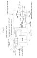
Fig. 3 is a circuit diagram of hydraulic components including hydraulic pump, control valve, actuators and hydraulic piping in the first embodiment; -
Fig. 4 is a diagrammatic illustration showing arrangement of a post-treatment system along with an engine; -
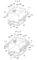
Fig. 5 is a schematic perspective view on an enlarged scale of a ureal water tank having enfolded therearound with working mechanism operating conduit; -
Fig. 6 is a schematic perspective view on an enlarged scale of a ureal water tank having enfolded therearound with working mechanism operating conduit in a first modification according to the present invention; -
Fig. 7 is a schematic plan view of an upper revolving structure in a second embodiment of the invention, with a housing cover removed to show the inside; -
Fig. 8 is a circuit diagram of a hydraulic system including hydraulic pump, control valve, actuators and various hydraulic conduits in the second embodiment; -
Fig. 9 is a schematic perspective view on an enlarged scale of a ureal water tank having enfolded therearound with an oil cooler side return conduit; -
Fig. 10 is a schematic plan view of an upper revolving structure in a third embodiment of the present invention, with a housing cover removed to show the inside; -
Fig. 11 is a schematic perspective view on an enlarged scale of a ureal water tank having enfolded therearound with a couple of working mechanism operating conduits; -
Fig. 12 is a schematic perspective view on an enlarged scale of a ureal water tank and working mechanism operating conduits in a second modification according to the present invention; -
Fig. 13 is a circuit diagram of a hydraulic system including hydraulic pump, control valve, actuators and various conduits in a fourth embodiment of the present invention; and -
Fig. 14 is a schematic perspective view on an enlarged scale of a ureal water tank and a working mechanism operating conduit in a third modification according to the present invention. - Hereafter, with reference to the accompanying drawings, the present invention is described more particularly by way of its preferred embodiments which are applied by way of example to a crawler type hydraulic excavator, typical of automotive construction machines.
- Shown in
Figs. 1 through 5 is an automotive construction machine in a first embodiment of the present invention. In this first embodiment, a working mechanism operating conduit which is connected between a control valve and an actuator of a working mechanism is utilized as an operating oil conduit to be enfolded around exterior surfaces of a ureal water tank. - In the first place, given below is a description on the construction of a hydraulic excavator which is shown in
Fig. 1 as an example of automotive construction machines. - The hydraulic excavator 1 is largely constituted by a vehicular
lower structure 2, an upper revolvingstructure 4 which is revolvably mounted on the vehicularlower structure 2 through a revolving mechanism 3, and a working mechanism 5 liftably supported at the front of the upper revolvingstructure 4. In this instance, the vehicularlower structure 2 and the upper revolvingstructure 4 constitute an automotive vehicle according to the present invention. - The vehicular
lower structure 2 is largely constituted by atruck frame 2A, right and left drive wheels 2B provided in a rear side of thetruck frame 2A, right and left idle wheels 2C provided in a front side of thetruck frame 2A, right and left crawler belts 2D (only right ones of the foregoing paired components are shown in the drawing) which are winded around the drive wheels 2B and idle wheels 2C, right and leftvehicle drive motors 2E (both of which are shown inFig. 3 ) which drive the afore-mentioned drive wheels 2B as an actuator. As pressurized oil is supplied to thevehicle drive motors 2E through motor drive conduits (not shown), the drive wheels 2B are rotatively driven from thevehicle drive motors 2E to turn around the crawler belts 2D. - The working mechanism 5 is composed of a boom 5A having a boom foot portion pivotally supported at a front center position in a front side of a revolving
frame 6 which will be described hereinafter, an arm 5B pivotally supported at the fore end of the boom 5A, a bucket 5C pivotally supported at the fore end of the arm 5B, right and leftboom cylinders 5D (both of which are shown inFig. 3 ) in a role of driving the boom 5A, an arm cylinder 5E in a role of driving thearm 58, and a bucket cylinder 5F in a role of driving the bucket 5C. Theboom cylinders 5D, arm cylinder 5E and bucket cylinder 5F are put in operation as actuators of the hydraulic excavator 1, and are heat sources which elevate the temperature of operating oil. - On the other hand, the upper revolving
structure 4 is largely constituted by a revolvingframe 6, cab 7,engine 8,radiator 10,oil cooler 11,hydraulic pump 13, operatingoil tank 14,fuel tank 15, operatingoil conduit 18,post-treatment system 24,ureal water tank 28, which will be described hereinafter. - Indicated at 6 is a revolving frame on the upper revolving
structure 4, the revolvingframe 6 being mounted on thetruck frame 2A through a revolving mechanism 3. As shown inFig. 2 , the revolvingframe 6 is composed of athick bottom plate 6A which is extended in forward and rearward directions, a left vertical plate 6B and a rightvertical plate 6C which are erected on thebottom plate 6A and extended in forward and rearward directions in laterally spaced relation with each other, a plural number ofextension beams 6D which are extended outward from the respectivevertical plates 6B and 6C, and aleft side frame 6E and aright side frame 6F which are attached to outer ends of the extension beams 6D and extended in forward and rearward directions at laterally outermost positions. Further, autility room 6G is defined in a right front side position on the revolvingframe 6 by the right extension beams 6D andright side frame 6F. - Indicated at 7 is a cab which is mounted on a left front side of the revolving
frame 6. This cab 7 is occupied by an operator. An operator's seat to be seated by an operator and various control levers (not shown in the drawings) are provided internally of the cab 7. - Indicated at 8 is an engine which is mounted transversely in a rear side of the revolving
frame 6 as a power source. In this case, theengine 8 is a Diesel engine. Anexhaust pipe 9 is extended from front side to right side of theengine 8 for discharging engine exhaust gases. - In this instance, the
Diesel engine 8 is operative with high efficiency and durability but emits noxious substances such as nitrogen oxides (NOx) and particulate matter (PM) in its exhaust gases. Therefore, apost-treatment system 24, having aNOx purifying device 27 within atubular casing 25 as shown inFig. 4 , is attached to theexhaust pipe 9 thereby to get rid of emissions of nitrogen oxides (NOx) in engine exhaust gases. - Indicated at 10 is a radiator for cooling down engine cooling water, and at 11 is an oil cooler for cooling down heated operating oil. These
radiator 10 and oil cooler 11 are located side by side on the left side of theengine 8. - In this instance, the
oil cooler 11 serves to cool down heated operating oil on return from therespective actuators 5D, 5E and 5F of the working mechanism 5 through thecontrol valve 16. For this purpose, the inlet side of theoil cooler 11 is connected to acontrol valve 16, which will be described hereinafter, through an oil cooler side returnconduit 22, while its outlet side is connected to an operatingoil tank 14 through a tank side returnconduit 23. - On the other hand, indicated at 12 is an oil pressure source which is, as shown in
Fig. 3 , constituted by a combination of ahydraulic pump 13 and an operatingoil tank 14. Namely, thereference numeral 13 denotes a hydraulic pump which is attached to the right side of theengine 8 to constitute anoil pressure source 12 along with an operatingoil tank 14. Thishydraulic pump 13 is driven by theengine 8 and can serve as a heat source. Further, the inlet side of thehydraulic pump 13 is connected to the operatingoil tank 14 through an operatingoil supply conduit 19, while its outlet side is connected to thecontrol valve 16 through a pressurizedoil supply conduit 20. - Further, indicated at 14 is an operating oil tank which is mounted in a right side section of the revolving
frame 6 on the front side of thehydraulic pump 13 to constitute theoil pressure source 12 along with thehydraulic pump 13. This operatingoil tank 14 serves as a storage of operating oil to be supplied to thehydraulic pump 13. On the other hand, indicated at 15 is a fuel tank (seeFig. 2 ) which is located on the front side of the operatingoil tank 14,and thisfuel tank 15 is serving as a storage of a fuel to be supplied to theengine 8. - Designated at 16 is a control valve which is provided on the revolving
frame 6, on the front side of theengine 8. By and through thiscontrol valve 16, in response to operations of control levers in the cab 7, pressurized oil from thehydraulic pump 13 is supplied to and from each one of thevehicle drive motors 2E,actuator cylinders 5D, 5E and 5F of the working mechanism 5, and a revolvingmotor 17 which is described below. - Indicated at 17 is a revolving motor which is provided on the revolving
frame 6 at a position on the front side of thecontrol valve 16. This revolvingmotor 17 constitutes part of the revolving mechanism 3 which puts the upper revolvingstructure 4 in a revolving motion on the vehicularlower structure 2, and serves as one of actuators. - Now, referring to
Figs. 2 and3 , of various hydraulic oil systems on the hydraulic excavator 1, a description is given below on an operatingoil conduit 18 which is connected with therespective cylinders 5D, 5E and 5F of the working mechanism 5. This operatingoil conduit 18 is connected with thevehicle drive motors 2E of the vehicularlower structure 2, therespective cylinders 5D, 5E and 5F of the working mechanism 5,oil cooler 11,hydraulic pump 13, operatingoil tank 14,control valve 16 and revolvingmotor 17 for circulation of operating oil. - Namely, the operating
oil conduit 18 includes a plural number of conduits through which operating oil (pressurized oil or return oil) is circulated in the order as described below. In this instance, the operatingoil conduit 18 is largely constituted by an operatingoil supply conduit 19 in a role of supplying operating oil from the operatingoil tank 14 to thehydraulic pump 13, a pressurizedoil supply conduit 20 in a role of supplying pressurized oil from thehydraulic pump 13 to thecontrol valve 16, workingmechanism operating conduit 21 in a role of conducting pressurized oil or return oil between each one of theboom cylinder 5D, arm cylinder 5E and bucket cylinder 5F of the working mechanism 5 and thecontrol valve 16, an oil cooler side returnconduit 22 in a role of circulating return oil from thecontrol valve 16 to theoil cooler 11, and a tank side returnconduit 23 in a role of circulating cooled return oil from theoil cooler 11 to the operatingoil tank 14. A description on the conduit between thecontrol valve 16,vehicle drive motor 2E and revolvingmotor 17 is omitted here although it is shown in the drawing. - The above-mentioned
operating oil conduit 18 releases heat to the outside as a result of circulation of operating oil and the temperature of the ureal water has been elevated to a higher level by released heat. Thus, this hot operating oil can be utilized as a heat source of a constant heat value. Further, generally the operatingoil conduit 18 is formed of a combination of metal conduits and joints, so that it can be located at an arbitrary position on the revolvingframe 6 with a high degree of freedom with respect to pipe angle and bending. - Now, described below by way of example is a first embodiment in which, among various working
mechanism operating conduits 21 to and from theactuators 5D, 5E and 5F, a workingmechanism operating conduit 21 from one of theboom cylinders 5D is arranged around theureal water tank 28. - Namely, in the first embodiment, the
ureal water tank 28 is kept in a heated state to prevent coagulation of an aqueous urea solution by the use of one of workingmechanism operating conduits 21 which is connected between thecontrol valve 16 and oneboom cylinder 5D for supplying and discharging operating oil to and from the latter. One end of this workingmechanism operating conduit 21 is connected to thecontrol valve 16, while the other end is connected to oneboom cylinder 5D of the working mechanism 5. Further, one workingmechanism operating conduits 21 of a pair of the workingmechanism operating conduits 21 is folded in U-shape on its way along theureal water tank 28 on a right front section of the revolvingframe 6 as shown inFigs. 2 ,3 and5 . - More particularly, a working
mechanism operating conduit 21 is composed of arear conduit section 21A extending in a rightward direction along a tank surface at the rear side surface 28B of theureal water tank 28, aright conduit section 21B extending in a forward direction along a tank surface at theright side surface 28D of theureal water tank 28, and a front conduit section 21C extending in a leftward direction along a tank surface at thefront side surface 28A of theureal water tank 28. This pipe arrangement makes it possible to route therespective conduit sections ureal water tank 28, even in case theureal water tank 28 is located in theutility room 6G in a right front section of the revolvingframe 6, which can be readily accessible at the time of refilling theureal water tank 28. Theureal water tank 28 is enclosed by therespective conduit sections ureal water tank 28 can be uniformly heated from around by hot pressure oil in circulation through therespective conduit sections - Now, described below is a
post-treatment system 24 which is connected on theexhaust pipe 9 of theengine 8 as an exhaust gas depurator as shown inFigs. 2 and4 . - Namely, built into the
post-treatment system 24 is aNOx purifying device 27, which will be described hereinafter, for purifying NOx in engine exhaust gases by the use of an aqueous urea solution. Thepost-treatment system 24 is largely constituted by atubular casing 25 and aNOx purifying device 27, as described below. - Indicated at 25 is a tubular casing of the
post-treatment system 24, thetubular casing 25 being in the form of a hollow tube which is extended in forward and rearward directions. Packed in thetubular casing 25 is a ureaselective reduction catalyst 27A of theNOx purifying device 27, along with an oxidation catalyst 27B. Thetubular casing 25 is connected to theengine exhaust pipe 9 of theengine 8 at its fore end, and to atail pipe 26 at its rear end. - Denoted at 27 is a NOx purifying device which is accommodated in the
tubular casing 25. TheNOx purifying device 27 plays a role of depurating nitrogen oxides (NOx) in engine exhaust gases by the use of an aqueous urea solution. Further, theNOx purifying device 27 is largely constituted by a ureaselective reduction catalyst 27A which is accommodated, for example, in an upstream side of thetubular casing 25, an oxidation catalyst 27B which is located on the downstream side of the ureaselective reduction catalyst 27A, and a urealwater injection valve 27C which is provided, for example, in theexhaust pipe 9 on the upstream side of the ureaselective reduction catalyst 27A. Further the urealwater injection valve 27C is connected to theureal water tank 28 through a urealwater supply conduit 30 and asupply pump 31, which will be described hereinafter. - In this instance, the
NOx purifying device 27 is adapted to inject an aqueous urea solution into exhaust gases from the urealwater injection valve 27C and to decompose NOx in engine exhaust gases into water and nitrogen through a reducing reaction by the use of ammonia which is generated from the aqueous urea solution by the ureaselective reduction catalyst 27A. Then, the exhaust gas is treated with the oxidation catalyst 27B to decrease the ammonia content in engine exhaust gases. - Further, the
ureal water tank 28, a storage of an aqueous urea solution to be injected into the exhaust gas on the upstream side of the ureaselective reduction catalyst 27A of theNOx purifying device 27, is arranged in the manner as described below. - The
ureal water tank 28 is fixedly set in position within theutility room 6G of the revolvingframe 6, for example, through amount frame 29. Moreover theureal water tank 28 is connected with the urealwater injection valve 27C through a urealwater supply conduit 30 and asupply pump 31. Further theureal water tank 28 is in the form of a polyhedral container (e.g., a hexahedral container) which is composed of various sides. - Namely, as shown in
Fig. 5 , an exterior surface of theureal water tank 28 is in the form of a closed hexahedral container having afront side surface 28A, a rear side surface 28B, aleft side surface 28C, aright side surface 28D, anupper side surface 28E and alower side surface 28F. Acap 28G is put on theupper side surface 28E, and the urealwater supply conduit 30 is connected to thelower side surface 28F. Further, a front conduit section 21C of the workingmechanism operating conduit 21 is positioned as to run along thefront side surface 28A, arear conduit section 21A is positioned as to run along the rear side surface 28B, and aright conduit section 21B is positioned as to run along theright side surface 28D of theureal water tank 28. - In this instance, the
ureal water tank 28 is set in theutility room 6G in a right front side section of theswing frame 6, i.e., in a place which is easily accessible from outside and usually used as a tool box room. The utility room can be accessible simply by opening afront cover portion 33E of ahousing cover 33, which will be described hereinafter, permitting to carry out various jobs in a facilitated manner, including a tank refilling job, inspection and maintenance and service work. On the other hand, there is no heat source component like anengine 8 in theutility room 6G. Therefore, if the ambient temperature drop to a level around -11 °C, coagulation would occur to the aqueous urea solution, and it would become difficult to feed the urea solution to theNOx purifiying device 27. - However, even if there is no heat source in the environs, the
ureal water tank 28 can be heated from around by the use of the heat of radiated from operating oil (pressurized oil or return oil), by changing the route of the workingmechanism operating conduit 21 in such a way as to enclose theureal water tank 28. - Indicated at 32 is a counterweight which is attached to a rear end of the revolving
frame 6 on the rear side of theengine 8. Thiscounterweight 32 works as a weight balance relative to the working mechanism 5. - Denoted at 33 is a housing cover which is built on the revolving
frame 6 for housing theengine 8,control valve 16 andureal water tank 28. Thishousing cover 33 includes a plural number of openableside cover portions 33A to 33D which covered both sides can be opened to uncover, and afront cover portion 33E positioned in the right forward portion which openably and closacly cover theureal water tank 28 and the like. - Being arranged as described above, the hydraulic excavator 1 of the first embodiment is put in operation in the manner as follows.
- In the first place, an operator gets into the cab 7 on the upper revolving
structure 4 and starts theengine 8 to put thehydraulic pump 13 in operation. Whereupon, operating oil in the operatingoil tank 14 is supplied to thehydraulic pump 13 through the operatingoil supply conduit 19 of the operatingoil conduit 18, and pressurized oil which is discharged from thehydraulic pump 13 is supplied to thecontrol valve 16 through the pressurizedoil supply conduit 20. A vehicle drive control lever in the cab 7 is manually shifted by the operator to supply pressurized oil to thevehicle drive motors 2E from thecontrol valve 16 to drive the vehicularlower structure 2 in a forward or reverse position. On the other hand, when working mechanism control levers are manipulated by the operator, pressurized oil is supplied to therespective cylinders 5D, 5E and 5F of the working mechanism 5 from thecontrol valve 16 through the workingmechanism operating conduits 21 to lift up and down the working mechanism 5 to carry out a ground excavation work. - Return oil which is returned to the
control valve 16 from the vehicularlower structure 2 and the working mechanism 5 is elevated in temperature by the heat which is generated by operation of thecylinders 5D, 5E or 5F, and therefore fed to theoil cooler 11 through the oil cooler side returnconduit 22 for cooling purposes. Operating oil which has been cooled down at theoil cooler 11 is returned to the operatingoil tank 14 through the tank side returnconduit 23. - Further, when the
engine 8 is in operation, emissions of nitrogen oxides (NOx) occur in theexhaust pipe 9. Therefore, an aqueous urea solution in theureal water tank 28 is fed to the urealwater injection valve 27C of theNOx purifying device 27 by thesupply pump 31 through the urealwater supply conduit 30. Thus, the aqueous urea solution is injected into engine exhaust gases from the urealwater injection valve 27C of theNOx purifying device 27 to generate ammonia. As a result, nitrogen oxides are reduced and decomposed into water and nitrogen by the ureaselective reduction catalyst 27A. And, the exhaust gas is then discharged to the outside through the oxidation catalyst 27B. - Moreover, at a working site in a cold district where the outside air temperature gets below -10 °C, for example, coagulation (freeze) may occur to an aqueous urea solution in the
ureal water tank 28, rendering the depuration of exhaust gases by theNOx purifying device 27 infeasible. However, by circulation of hot operating oil (pressurized oil or return oil) through the workingmechanism operating conduit 21 which is enfolded around theureal water tank 28, the aqueous urea solution in thetank 28 is directly heated and kept in a liquid state. - Thus, according to the first embodiment, the
ureal water tank 28, which is a storage of the aqueous ureal solution, is installed in theutility room 6G in a right front side section on the revolvingframe 6, which is readily accessible from outside. Furthermore, a workingmechanism operating conduit 21 of the operatingoil conduit 18, which supplies operating oil to and from aboom cylinder 5D of the working mechanism 5, is routed to run along exterior surfaces of theureal water tank 28. Thus, even if no heat source component exists in the environs of theureal water tank 28, theureal water tank 28 can be heated from around in a hot state by the heat which is radiated from the operating oil (pressurized oil or return oil) in circulation through the workingmechanism operating conduit 21. - Thus, even in an operation in a cold district, the aqueous urea solution in the
ureal water tank 28 is heated by the operating oil in circulation through the workingmechanism operating conduit 21, preventing coagulation of the aqueous urea solution which might otherwise be caused by a temperature drop, thus enhancing the reliability of theNOx purifying device 27. Besides, theureal water tank 28 is placed in theutility room 6G on the revolvingframe 6, which is readily accessible from outside, to facilitate a tank refilling job and maintenance work as well. - Further, the operating oil in circulation through the working
mechanism operating conduit 21 repeatedly undergoes a temperature increase by pressurization and a temperature drop by the cooling effects of theoil cooler 11, within a certain temperature range. That is to say, the aqueous urea solution in theureal water tank 28 can be kept in a certain temperature range in an extremely simplified manner by utilization of the heat of operating oil running through the workingmechanism operating conduit 21, without necessitating a highly developed temperature control. - On the other hand, the working
mechanism operating conduit 21 is provided with a foldedrear conduit section 21A,right conduit 21B and front conduit section 21C of U-shape within its length, the foldedrespective conduit sections right side surface 28D andfront side surface 28A of theureal water tank 28. Thus, heat is applied to theureal water tank 28 from threeside surfaces - Further, since the
ureal water tank 28 is located in theutility room 6G in a right front side section of the revolvingframe 6, the aqueous urea solution in theureal water tank 28 can be heated simply by routing and enfolding a workingmechanism operating conduit 21 to or from the working mechanism 5, producing sufficient heating effects by a simple pipe arrangement. - In the first embodiment, of the two working
mechanism operating conduits 21 which are connected between theboom cylinders 5D and thecontrol valve 16, by way of example one workingmechanism operating conduit 21 is arranged to run along lateral surfaces of theureal water tank 28. However, needless to say, the present invention is not limited to the example shown. For instance, as in a first modification shown inFig. 6 , a couple of workingmechanism operating conduits 21 may be arranged to run along exterior surfaces of theureal water tank 28 to heat the latter at a higher speed. - Now, turning to
Figs. 7 through 9 , there is shown an automotive construction machine according to a second embodiment of the invention. This embodiment has a feature in that an oil cooler side return conduit between a control valve and an oil cooler is arranged to run along four lateral sides of a ureal water tank. In the following description of the second embodiment, those component parts which are identical with a counterpart in the foregoing first embodiment are simply designated by the same reference numeral or character to avoid repetitions of similar explanations. - Indicated at 41 is an operating oil conduit adopted in the second embodiment. Substantially in the same manner as the operating
oil conduit 18 in the first embodiment, this operatingoil conduit 41 is largely constituted by an operatingoil supply conduit 42 for supplying operating oil from an operatingoil tank 14 to ahydraulic pump 13, a pressurizedoil supply conduit 43 for supplying pressurized oil from thehydraulic pump 13 to acontrol valve 16, a workingmechanism operating conduit 44 connected between thecontrol valve 16 and a working mechanism 5 for supplying operating oil to and from therespective cylinders 5D, 5E and 5F, an oil cooler side returnconduit 45 for circulation of return oil from thecontrol valve 16 to anoil cooler 11, and a tank side returnconduit 46 for returning cooled return oil from theoil cooler 11 to an operatingoil tank 14. - However, the operating
oil conduit 41 of the second embodiment differs from the operatingoil conduit 18 in the first embodiment in that the oil cooler side returnconduit 45 is routed around aureal water tank 47, which will be described hereinafter, to serve as a heater conduit. - As shown in
Fig. 8 , the oil cooler side returnconduit 45 is connected to thecontrol valve 16 at its one end, and to an inlet side of theoil cooler 11 at the other end. In a space between a cab 7 and an engine 8 (the oil cooler 11), the oil cooler side returnconduit 45 is bent into a square shape in such a way as to substantially enclose four lateral sides of aureal water tank 47 in four conduit sections. - More specifically, as shown in
Fig. 7 , the oil cooler side returnconduit 45 intersect the left vertical plate 6B of the revolvingframe 6, and the conduit is arranged to include a control valveside conduit section 45A which is extended from acontrol valve 16 toward theureal water tank 47 along the rear side of the cab 7, a right conduit section 45B which is bent forward the cab 7 at a fore end of the control valveside conduit section 45A, afront conduit section 45C which is bent leftward along the rear side of the cab 7 at a fore end of the right conduit section 45B, aleft conduit section 45D which is bent rearward along aside cover portion 33A of ahousing cover 33 at a fore end of thefront conduit section 45C, arear conduit section 45E which is bent rightward at a fore end of theleft conduit section 45D at a position beyond aureal water tank 47, and an oil coolerside conduit section 45F which is bent toward theoil cooler 11 at a fore end of therear conduit section 45E. - As shown in
Fig. 9 , the oil cooler side returnconduit 45 is arranged to enfold theureal water tank 47 by locating its right conduit section 45B to run along right side surface 47D of theureal water tank 47,front conduit section 45C to run alongfront side surface 47B of theureal water tank 47, leftconduit section 45D to run along left side surface 47C of theureal water tank 47 andrear conduit section 45E to run alongrear side surface 47B of theureal water tank 47. Thus, the oil cooler side returnconduit 45 can heat the aqueous urea solution in theureal water tank 47 uniformly from foursides - Indicated at 47 is a ureal water tank which is adopted in the second embodiment. This
ureal water tank 47 is located in a so-called utility room which is located between cab 7 and engine 8 (oil cooler 11) in an outmost (leftmost) side section which is readily accessible from outside at the time of refilling. Theureal water tank 47 is fixedly set in position, for example, on amount frame 48, and connected to a urealwater injection valve 27C through a urealwater supply conduit 49 and asupply pump 50. - Substantially in the same way as the
ureal water tank 28 in the foregoing first embodiment, a surface of theureal water tank 47 is in the form of a closed hexahedral container includingfront side surface 47A,rear side surface 47B, left side surface 47C, right side surface 47D,upper side surface 47E andlower side surface 47F. A cap 47G is put on theupper side surface 47E of thetank 47. Theureal water tank 47 is folded by thefront conduit section 45C of the oil cooler side returnconduit 45 which is positioned to run along thefront side surface 47A,rear conduit section 45E which is positioned to run along therear side surface 47B,left conduit section 45D which is positioned to run along the left side surface 47C, and right conduit section 45B which is positioned to run along the right side surface 47D. - Being arranged as described above, the second embodiment of the invention can produce substantially the same effects as the foregoing first embodiment. Especially in the second embodiment, the oil cooler side return
conduit 45 extending toward the oil cooler 11 from thecontrol valve 16 is used as an operatingoil conduit 41 to be routed along exterior surfaces of theureal water tank 47 for heating an aqueous urea solution in theureal water tank 47. When refilling an aqueous urea solution, theureal water tank 47 can be accessed simply by opening theside cover portion 33A of thehousing cover 33 as indicated by two-dot chain line inFig. 7 . - Besides, the oil cooler
side return pipe 45 is formed withrespective conduit sections ureal water tank 47 from four sides. More specifically, therespective conduit sections front side 47A, left side 47C andrear side 47B of theureal water tank 47. Thus, of exterior surfaces of theureal water tank 47, heat can be applied from exterior surfaces of the foursides - Now, turning to
Figs. 10 and11 , there is shown a third embodiment of the invention. This embodiment has a feature in that a ureal water tank is located in the vicinity of a swing motor, and a couple of working mechanism operating conduits, which are connected between a control valve and a boom cylinder of a working mechanism, are arranged to run along upper and lower sides of the ureal water tank. In the following description of the third embodiment, those component parts which are identical with a counterpart in the foregoing first embodiment are simply designated by the same reference numeral or character to avoid repetitions of similar explanations. - Indicated at 51 is an operating oil conduit in the third embodiment. Similarly to the
operation oil conduit 18 in the first embodiment, the operatingoil conduit 51 is largely constituted by an operatingoil supply conduit 52, a pressurized oil supply conduit 53, a workingmechanism operating conduit 54, an oil cooler side returnconduit 55, and a tank side returnconduit 56. - Denoted at 57 is a ureal water tank adopted in the third embodiment. Substantially in the same way as the
ureal water tank 28 in the first embodiment, thisureal water tank 57 is formed in the shape of a closed hexahedral container havingfront side surface 57A,rear side surface 57B,left side surface 57C, right side surface 57D,upper side surface 57E andlower side surface 57F. Acap 57G is fitted on said upper side surfaces 57E. Further, theureal water tank 57 is fixedly set in position on amount frame 58, and connected to a urealwater injection valve 27C through a urealwater supply conduit 59 and asupply pump 60. - The operating
oil conduit 51 in the third embodiment differs from the operatingoil conduit 18 of the first embodiment in that a couple of workingmechanism operating conduits 54 are used as heater conduits for heating theureal water tank 57. - Each one of the two working
mechanism operating conduits 54 is connected to thecontrol valve 16 at one end thereof, and to aboom cylinder 5D of a working mechanism 5 at the other end through left and rightvertical plates 6B and 6C of a revolvingframe 6. The two workingmechanism operating conduits 54 are located in vertically different positions relative to each other. Namely, one of the two workingmechanism operating conduits 54 is arranged to run along a route at a higher level and the other workingmechanism operating conduit 54 is arranged to run along a route at a lower level. Thus, as shown inFig. 11 , one workingmechanism operating conduit 54 is arranged to run along theupper side surface 57E of theureal water tank 57, while the other workingmechanism operating conduit 54 is arranged to run along thelower side surface 57F of theureal water tank 57. Thus, the two workingmechanism operating conduits 54 are arranged to embrace the upper andlower side surfaces ureal water tank 57 to heat an aqueous urea solution uniformly. - Being arranged as described above, the third embodiment of the invention can produce substantially the same effects as the foregoing first embodiment. Especially in the third embodiment, an aqueous urea solution can be heated uniformly from upper and lower sides by the two working
mechanism operating conduits 54 which are arranged to along the top and lower sides of theureal water tank 57. - Further, in the third embodiment, by way of example, one of two working
mechanism operating conduits 54, which are connected between thecontrol valve 16 andboom cylinders 5D, is arranged to run along anupper side surface 57E of theureal water tank 57, while the other workingmechanism operating conduit 54 is arranged to run along alower side surface 57F of theureal water tank 57. However, the present invention is not limited to this particular example shown. For instance, as in a second modification ofFig. 12 , there may be employed four workingmechanism operating conduits 54 to run along exterior surface of theureal water tank 57 in total, routing two workingmechanism operating conduits 54 to run along anupper side surface 57E of aureal water tank 57, while routing the other two workingmechanism operating conduits 54 to run along alower side surface 57F of theureal water tank 57. - Now, turning to
Fig. 13 , there is shown a fourth embodiment of the automotive construction machine according to the invention. This embodiment has a feature in that, a pressurized oil supply conduit, which is connected between a hydraulic pump and a control valve, is arranged to run along exterior surfaces of a ureal water tank. In the following description of the fourth embodiment, those component parts which are identical with a counterpart in the foregoing first embodiment are simply designated by the same reference numeral or character to avoid repetitions of similar explanations. - Indicated at 61 is an operating oil conduit in the fourth embodiment. Substantially in the same way as the operating
oil conduit 18 in the first embodiment, the operatingoil conduit 61 is largely constituted by an operatingoil supply conduit 62, a pressurizedoil supply conduit 63, workingmechanism operating conduits 64, an oil cooler side return conduit 65 and a tank side returnconduit 66. Denoted at 67 is a ureal water tank. Besides thisureal water tank 67 is in the form of a closed hexahedral container similar to theureal water tank 28 in the first embodiment. - The operating
oil conduit 61 in the fourth embodiment differs from the operatingoil conduit 18 in the first embodiment in that the pressurizedoil supply conduit 63 is used for heating theureal water tank 67. - One end of the pressurized
oil supply conduit 63 is connected to thehydraulic pump 13, while the other end is connected to thecontrol valve 16. The pressurizedoil supply conduit 63 is bent, for example, in U-shape to fold in exterior surfaces of theureal water tank 67. Thus, the pressurizedoil supply conduit 63 can heat an aqueous urea solution in theureal water tank 67 uniformly, for example, from three lateral sides of theureal water tank 67 by the use of heat of pressurized oil which is in supply from thehydraulic pump 13 to thecontrol valve 16. - Being arranged as described above, the fourth embodiment can produce substantially the same effects as the foregoing first embodiment. Especially in the fourth embodiment, the pressurized
oil supply conduit 63, which connects thehydraulic pump 13 with thecontrol valve 16, is arranged to run along exterior surfaces of theureal water tank 67. Thus, an aqueous urea solution in theureal water tank 67 can be heated by the heat of pressurized oil in circulation between thehydraulic pump 13 andcontrol valve 16. - In the above-described first embodiment, by way of example, the working
mechanism operating conduit 21 which is connected to aboom cylinder 5D is used for heating theureal water tank 28. However, needless to say, the present invention is not limited to this particular example. For instance, theureal water tank 28 may be heated by the use of other workingmechanism operating conduit 21 which is connected with the arm cylinder 5E or with the bucket cylinder 5F. - Further, in the first embodiment, by way of example, part of the working mechanism operating
oil conduit 21 is bent in U-shape to provide therear conduit section 21A,right conduit section 21B and front conduit section 21C, and theserear conduit section 21A,right conduit section 21B and front conduit section 21C run along exterior surfaces at the rear side surface 28B,right side surface 28D andfront side surface 28A of theureal water tank 28, respectively. - However, in this regard, the present invention is not limited to the particular example shown. For instance, as in a third modification of the invention shown in
Fig. 14 , part of a workingmechanism operating conduit 71 may be bent to provide alower conduit section 71A, a right conduit section 71B and an upper conduit section 71C and theselower conduit section 71A, right conduit section 71B, and upper conduit section 71C run along exterior surfaces at thelower side surface 28F,right side surface 28D andupper side surface 28E of theureal water tank 28, respectively. Otherwise, the working mechanism operatingoil conduit 71 may be bent in different directions to run along different sides of the ureal water tank. The same structure applies to other embodiments of the invention. - Further, by way of example one working
mechanism operating conduit 21 is arranged to run along exterior surfaces of theureal water tank 28 in the first embodiment, a couple of workingmechanism operating conduits 21 are arranged to run along exterior surfaces of theureal water tank 28 in the first modification, and a couple of working mechanism operatingoil conduits 54 are arranged to run along exterior surfaces of theureal water tank 58 in the third embodiment of the invention. However, the present invention is not limited to these particular examples. If desired, three or more operating oil conduits may be arranged in such a way as to enfold the ureal water tank. - Furthermore, a working
mechanism operating conduit 21 is routed around theureal water tank 28 in the first embodiment, an oil cooler side returnconduit 45 is routed around theureal water tank 47 in the second embodiment, a working mechanism operatingoil conduit 54 is routed around theureal water tank 58 in the third embodiment, and a pressurizedoil supply conduit 63 is routed around theureal water tank 67 in the fourth embodiment. However, the present invention is not limited to these particular examples. For instance, a conduit which is connected to thevehicle drive motor 2E of the vehicularlower structure 2 or to the revolvingmotor 17 may be arranged to run along exterior surfaces of a ureal water tank. - On the other hand, by way of example, the above-described first embodiment employs the
ureal water tank 28 in the form of a closed hexahedral container, having thefront side surface 28A, rear side surface 28B,left side surface 28C,right side surface 28D,upper side surface 28E andlower side surface 28F. However, the present invention is not limited to this particular example. For instance, the ureal water tank may be a container of a pentahedral, heptahedral or other polyhedral shape. If desired, there may be employed a ureal water tank of other shapes, for example of a cylindrical or flattened spherical shape. The same structure applies to other embodiments of the present invention. - Further, in the foregoing embodiments, the present invention is applied to a crawler type hydraulic excavator 1 which is typical of automotive construction machines. However, the present invention is not limited to can be similarly applied to wheel type excavators and a wide variety of other automotive construction machines such as lift trucks, dump trucks, wheel loaders, hydraulic cranes and bulldozers.
Claims (6)
- An automotive construction machine having a vehicle structure driven by a vehicle drive motor, a working mechanism operated by actuators mounted on said vehicle structure, an engine mounted on said vehicle structure to drive a hydraulic pump at the task of delivering pressurized oil, operating oil conduits for circulation of operating oil located between an oil pressure source-which is comprised of said hydraulic pump and an operating oil tank, and various actuators including said vehicle drive motor of said vehicle structure and actuators of said working mechanism through a control valve, a urea selective reduction catalyst provided in an exhaust pipe of said engine to get rid of nitrogen oxides, and a ureal water tank storing an aqueous urea solution to be injected into said exhaust pipe of said engine on the upstream side of said urea selective reduction catalyst,
characterized in that:one of said operating oil conduits is routed to run along exterior surfaces of said ureal water tank; andheating said aqueous urea solution in said tank by heat radiation from pressurized oil or return oil in circulation through said operating oil conduit. - An automotive construction machine as defined in claim 1, wherein said ureal water tank is in the form of a polyhedral container which is constituted by various sides, and said operating oil conduit is arranged to run at least along two sides of said various sides.
- An automotive construction machine as defined in claims
1 or 2, wherein said operating oil conduit connected between said control valve and an actuator of said working mechanism is a working mechanism operating conduit, said working mechanism operating conduit being arranged to run along exterior surfaces of said ureal water tank. - An automotive construction machine as defined in claim 1 or 2, wherein an oil cooler is provided between said control valve and said operating oil tank to cool down return oil from said actuator, said operating oil conduit connected between said control valve and said oil cooler is an oil cooler side return conduit, and said oil cooler side return conduit is arranged to run along exterior surfaces of said ureal water tank.
- An automotive construction machine as defined in claim 1 or 2, wherein said operating oil conduit connected between said hydraulic pump and said control valve is a pressurized oil supply conduit, and said pressurized oil supply conduit is arranged to run along exterior surfaces of said ureal water tank.
- An automotive construction machine as defined in claim 1, wherein said automotive vehicular structure is composed of a vehicular lower structure driven by said vehicle drive motor, and an upper revolving structure which is swingably mounted on said vehicular lower structure, having an engine mounted in a rear side of a revolving frame to drive said hydraulic pump and having said working mechanism built in a front side of said revolving frame, and said ureal water tank is located on said upper revolving structure.
Applications Claiming Priority (2)
| Application Number | Priority Date | Filing Date | Title |
|---|---|---|---|
| JP2007167686 | 2007-06-26 | ||
| PCT/JP2008/054546 WO2009001587A1 (en) | 2007-06-26 | 2008-03-06 | Self-propelled construction machine |
Publications (2)
| Publication Number | Publication Date |
|---|---|
| EP2172626A1 true EP2172626A1 (en) | 2010-04-07 |
| EP2172626A4 EP2172626A4 (en) | 2011-12-28 |
Family
ID=40185411
Family Applications (1)
| Application Number | Title | Priority Date | Filing Date |
|---|---|---|---|
| EP08721962A Withdrawn EP2172626A4 (en) | 2007-06-26 | 2008-03-06 | Self-propelled construction machine |
Country Status (6)
| Country | Link |
|---|---|
| US (1) | US8186156B2 (en) |
| EP (1) | EP2172626A4 (en) |
| JP (1) | JPWO2009001587A1 (en) |
| KR (1) | KR20100033482A (en) |
| CN (1) | CN101595284A (en) |
| WO (1) | WO2009001587A1 (en) |
Cited By (2)
| Publication number | Priority date | Publication date | Assignee | Title |
|---|---|---|---|---|
| EP2722446A4 (en) * | 2011-06-14 | 2015-02-25 | Hitachi Construction Machinery | Construction machine |
| EP3121400A4 (en) * | 2014-03-17 | 2017-09-06 | Hitachi Construction Machinery Co., Ltd. | Urea supply system for construction machine |
Families Citing this family (57)
| Publication number | Priority date | Publication date | Assignee | Title |
|---|---|---|---|---|
| JPWO2009001587A1 (en) * | 2007-06-26 | 2010-08-26 | 日立建機株式会社 | Self-propelled construction machinery |
| US8056671B2 (en) * | 2007-10-12 | 2011-11-15 | Mazda Motor Corporation | Exhaust-gas purification device disposition structure of vehicle |
| JP4928474B2 (en) * | 2008-01-08 | 2012-05-09 | 日立建機株式会社 | Arrangement structure of NOx reduction device for construction machinery |
| JP5172956B2 (en) * | 2008-05-22 | 2013-03-27 | 日立建機株式会社 | Construction machinery |
| JP4855491B2 (en) * | 2009-03-30 | 2012-01-18 | 住友建機株式会社 | Construction machinery |
| JP4855490B2 (en) * | 2009-03-30 | 2012-01-18 | 住友建機株式会社 | Construction machinery |
| JP4937291B2 (en) * | 2009-03-30 | 2012-05-23 | 住友建機株式会社 | Construction machinery |
| JP2011012661A (en) * | 2009-07-06 | 2011-01-20 | Sumitomo (Shi) Construction Machinery Co Ltd | Construction machine |
| JP2011011725A (en) * | 2009-07-06 | 2011-01-20 | Sumitomo (Shi) Construction Machinery Co Ltd | Construction machine |
| GB0913581D0 (en) * | 2009-08-05 | 2009-09-16 | Agco Gmbh | Tractors |
| WO2011027765A1 (en) * | 2009-09-02 | 2011-03-10 | 日立建機株式会社 | Wheel type working vehicle |
| JP5402451B2 (en) * | 2009-09-17 | 2014-01-29 | コベルコ建機株式会社 | Construction machinery |
| US8573505B1 (en) * | 2010-04-01 | 2013-11-05 | Dana A. Hennessy | Thawing system for machinery undercarriages |
| JP5228000B2 (en) * | 2010-05-26 | 2013-07-03 | 日立建機株式会社 | Hybrid construction machine |
| JP2011247232A (en) * | 2010-05-31 | 2011-12-08 | Caterpillar Sarl | Working machine |
| JP5580681B2 (en) * | 2010-07-22 | 2014-08-27 | 日立建機株式会社 | Electric work vehicle |
| JP5356341B2 (en) * | 2010-09-16 | 2013-12-04 | 日立建機株式会社 | Construction machinery |
| JP5562777B2 (en) * | 2010-09-16 | 2014-07-30 | 日立建機株式会社 | Construction machinery |
| JP2012082644A (en) * | 2010-10-14 | 2012-04-26 | Hitachi Constr Mach Co Ltd | Construction machine |
| CN101975128B (en) * | 2010-11-17 | 2013-10-16 | 中国第一汽车集团公司 | Pressureproof combined type fuel tank of column plastic pipe |
| CN102003314B (en) * | 2010-11-17 | 2013-10-30 | 中国第一汽车集团公司 | Three-post plastic-pipe pressure-resistance combined oil tank |
| CN101979257B (en) * | 2010-11-17 | 2013-12-25 | 中国第一汽车集团公司 | Pressure-resistant combined fuel tank with two-column plastic pipe |
| CN101973206B (en) * | 2010-11-17 | 2014-01-01 | 中国第一汽车集团公司 | Pressure proof combined type oil tank of multi-column plastic pipe |
| JP2012171596A (en) * | 2011-02-24 | 2012-09-10 | Hitachi Constr Mach Co Ltd | Construction machine |
| JP2012207552A (en) * | 2011-03-29 | 2012-10-25 | Hitachi Constr Mach Co Ltd | Construction machine |
| US20130026244A1 (en) * | 2011-07-28 | 2013-01-31 | Cnh America Llc | Work vehicle heating system and method |
| JP2013064255A (en) * | 2011-09-16 | 2013-04-11 | Kobelco Contstruction Machinery Ltd | Construction machine |
| JP5780078B2 (en) * | 2011-09-16 | 2015-09-16 | コベルコ建機株式会社 | Construction machinery |
| CN102444155B (en) * | 2011-10-17 | 2014-01-15 | 柳工常州挖掘机有限公司 | Construction machine |
| US9016418B2 (en) * | 2011-11-11 | 2015-04-28 | Hitachi Construction Machinery Co., Ltd. | Construction machine |
| KR101345371B1 (en) | 2012-01-13 | 2013-12-24 | 동양기전 주식회사 | Water heating system for special vehicles |
| JP2013181400A (en) * | 2012-02-29 | 2013-09-12 | Komatsu Ltd | Working machine |
| WO2013137169A1 (en) * | 2012-03-16 | 2013-09-19 | 日立建機株式会社 | Construction machine |
| JP5442829B1 (en) * | 2012-10-16 | 2014-03-12 | 株式会社小松製作所 | Excavator |
| PL2754870T3 (en) | 2013-01-11 | 2018-08-31 | Joseph Vögele AG | Road finisher with heat management system |
| WO2014125623A1 (en) * | 2013-02-15 | 2014-08-21 | 株式会社小松製作所 | Hydraulic shovel |
| US9003779B2 (en) | 2013-03-26 | 2015-04-14 | Komatsu Ltd. | Wheel loader |
| DE102013206589A1 (en) * | 2013-04-12 | 2014-10-16 | Deere & Company | heater |
| CN110219335B (en) * | 2013-10-08 | 2022-01-11 | 住友建机株式会社 | Excavator |
| JP5949793B2 (en) * | 2014-01-17 | 2016-07-13 | コベルコ建機株式会社 | Construction machinery |
| JP5895951B2 (en) * | 2014-01-23 | 2016-03-30 | コベルコ建機株式会社 | Construction machinery |
| JP5989017B2 (en) * | 2014-01-30 | 2016-09-07 | 日立建機株式会社 | Construction machinery |
| JP5940107B2 (en) * | 2014-03-17 | 2016-06-29 | 日立建機株式会社 | Urea water supply system for construction machinery |
| JP6303678B2 (en) * | 2014-03-20 | 2018-04-04 | コベルコ建機株式会社 | Upper swing body |
| JP6297905B2 (en) * | 2014-04-22 | 2018-03-20 | 日立建機株式会社 | Construction machinery |
| JP6307019B2 (en) * | 2014-11-28 | 2018-04-04 | 日立建機株式会社 | Construction machinery |
| JP6497060B2 (en) * | 2014-12-19 | 2019-04-10 | 株式会社タダノ | Rough terrain crane |
| JP6232370B2 (en) * | 2014-12-24 | 2017-11-15 | 株式会社Kcm | Construction machinery |
| JP6391522B2 (en) * | 2015-03-30 | 2018-09-19 | 株式会社クボタ | Working machine |
| JP6549455B2 (en) * | 2015-09-24 | 2019-07-24 | 住友建機株式会社 | Shovel |
| JP6445476B2 (en) * | 2016-01-29 | 2018-12-26 | 日立建機株式会社 | Construction machinery |
| JP6373291B2 (en) * | 2016-03-02 | 2018-08-15 | 日立建機株式会社 | Construction machinery |
| JP6518616B2 (en) * | 2016-03-29 | 2019-05-22 | 株式会社Kcm | Work vehicle |
| JP6593475B2 (en) * | 2018-02-07 | 2019-10-23 | コベルコ建機株式会社 | Construction machinery |
| JP2019056296A (en) * | 2018-11-21 | 2019-04-11 | 株式会社クボタ | Work machine |
| CN113653122B (en) * | 2021-09-26 | 2023-04-28 | 徐工集团工程机械股份有限公司科技分公司 | Tail sinking type rear frame structure with water tank tail gas treatment and arranged at side of cab |
| JP7710096B2 (en) * | 2022-03-30 | 2025-07-17 | 日立建機株式会社 | Construction Machinery |
Family Cites Families (22)
| Publication number | Priority date | Publication date | Assignee | Title |
|---|---|---|---|---|
| JP3709654B2 (en) * | 1997-05-21 | 2005-10-26 | 日立建機株式会社 | Soil improvement machine with excavation means |
| JP2000085617A (en) | 1998-09-11 | 2000-03-28 | Hitachi Constr Mach Co Ltd | Anti-freezing device for truck frames of construction machinery |
| JP4520649B2 (en) * | 2001-02-06 | 2010-08-11 | 株式会社小松製作所 | Hybrid construction machine |
| JP2003020936A (en) * | 2001-07-03 | 2003-01-24 | Komatsu Ltd | Arrangement structure of liquid reducing agent tank for NOx reduction catalyst |
| JP4115120B2 (en) | 2001-08-06 | 2008-07-09 | 株式会社小松製作所 | Exhaust gas purification device for internal combustion engine |
| JP3822133B2 (en) * | 2002-05-09 | 2006-09-13 | 株式会社クボタ | Hydraulic piping structure of swing work machine |
| DE10256727B4 (en) * | 2002-12-05 | 2017-02-16 | Magna Steyr Fuel Systems Gmbh Werk Schwäbisch Gmünd | Container for holding consumables |
| SE524926C2 (en) * | 2003-04-15 | 2004-10-26 | Volvo Constr Equip Holding Se | Liquid viscosity control system and method |
| JP2005248920A (en) * | 2004-03-08 | 2005-09-15 | Kobelco Contstruction Machinery Ltd | Construction machine |
| JP2006105014A (en) | 2004-10-05 | 2006-04-20 | Mitsubishi Fuso Truck & Bus Corp | Exhaust emission control device utilizing reducing agent |
| JP2006112496A (en) * | 2004-10-14 | 2006-04-27 | Hitachi Constr Mach Co Ltd | Grease warming device of construction machine |
| JP4424601B2 (en) * | 2004-10-27 | 2010-03-03 | 本田技研工業株式会社 | snowblower |
| US7503419B2 (en) * | 2005-09-26 | 2009-03-17 | Kubota Corporation | Backhoe |
| JP4530964B2 (en) * | 2005-09-30 | 2010-08-25 | 本田技研工業株式会社 | Power transmission device for vehicle |
| DE102005059581B4 (en) * | 2005-12-14 | 2009-02-26 | Man Nutzfahrzeuge Ag | Device for heating a tank for urea water solution |
| DE202005019499U1 (en) * | 2005-12-14 | 2006-02-09 | Man Nutzfahrzeuge Ag | Heating system for a vehicle tank, containing a solution of urea and water, has a tube to take a heat carrier flow pressed into a serpentine groove at the outer side of a tank wall |
| JP4527074B2 (en) * | 2006-03-13 | 2010-08-18 | ヤンマー株式会社 | Excavator |
| JP4981050B2 (en) * | 2006-08-02 | 2012-07-18 | 株式会社小松製作所 | Hybrid work vehicle |
| JP4996349B2 (en) * | 2007-05-31 | 2012-08-08 | 株式会社クボタ | Work vehicle cooling structure |
| JP5015670B2 (en) * | 2007-06-20 | 2012-08-29 | トヨタ自動車株式会社 | Control device for vehicle power transmission device |
| JPWO2009001587A1 (en) * | 2007-06-26 | 2010-08-26 | 日立建機株式会社 | Self-propelled construction machinery |
| JP2009013845A (en) * | 2007-07-03 | 2009-01-22 | Hitachi Constr Mach Co Ltd | Engine power machine |
-
2008
- 2008-03-06 JP JP2009520375A patent/JPWO2009001587A1/en active Pending
- 2008-03-06 US US12/519,450 patent/US8186156B2/en not_active Expired - Fee Related
- 2008-03-06 WO PCT/JP2008/054546 patent/WO2009001587A1/en not_active Ceased
- 2008-03-06 CN CNA2008800022395A patent/CN101595284A/en active Pending
- 2008-03-06 EP EP08721962A patent/EP2172626A4/en not_active Withdrawn
- 2008-03-06 KR KR1020097026671A patent/KR20100033482A/en not_active Withdrawn
Cited By (3)
| Publication number | Priority date | Publication date | Assignee | Title |
|---|---|---|---|---|
| EP2722446A4 (en) * | 2011-06-14 | 2015-02-25 | Hitachi Construction Machinery | Construction machine |
| EP3121400A4 (en) * | 2014-03-17 | 2017-09-06 | Hitachi Construction Machinery Co., Ltd. | Urea supply system for construction machine |
| US10066531B2 (en) | 2014-03-17 | 2018-09-04 | Hitachi Construction Machinery Co., Ltd. | Urea water supply system for construction machine |
Also Published As
| Publication number | Publication date |
|---|---|
| EP2172626A4 (en) | 2011-12-28 |
| WO2009001587A1 (en) | 2008-12-31 |
| US8186156B2 (en) | 2012-05-29 |
| US20100038162A1 (en) | 2010-02-18 |
| CN101595284A (en) | 2009-12-02 |
| JPWO2009001587A1 (en) | 2010-08-26 |
| KR20100033482A (en) | 2010-03-30 |
Similar Documents
| Publication | Publication Date | Title |
|---|---|---|
| US8186156B2 (en) | Automotive construction machine | |
| JP5688167B2 (en) | Construction machinery | |
| CN104040132B (en) | Reductant tank and working vehicle | |
| US10161107B2 (en) | Construction machine | |
| EP2722446A1 (en) | Construction machine | |
| CN104363984B (en) | Hydraulic crawler excavator | |
| EP2886816B1 (en) | Wheel loader with reducing agent tank | |
| JP4824606B2 (en) | Construction machinery | |
| WO2015045113A1 (en) | Reducing agent tank and work vehicle | |
| KR101834979B1 (en) | Construction machine | |
| US9574322B2 (en) | Hydraulic excavator | |
| US20160152131A1 (en) | Construction Machine | |
| US20160230633A1 (en) | Urea water supply system for construction machine | |
| JP5723494B1 (en) | Excavator | |
| JP2016188559A (en) | Working machine | |
| JP7594407B2 (en) | Construction Machinery | |
| JP7519325B2 (en) | Construction Machinery | |
| JP7478649B2 (en) | Construction Machinery | |
| JP2022076663A (en) | Construction machine | |
| KR101621674B1 (en) | Hydraulic excavator |
Legal Events
| Date | Code | Title | Description |
|---|---|---|---|
| PUAI | Public reference made under article 153(3) epc to a published international application that has entered the european phase |
Free format text: ORIGINAL CODE: 0009012 |
|
| 17P | Request for examination filed |
Effective date: 20100126 |
|
| AK | Designated contracting states |
Kind code of ref document: A1 Designated state(s): AT BE BG CH CY CZ DE DK EE ES FI FR GB GR HR HU IE IS IT LI LT LU LV MC MT NL NO PL PT RO SE SI SK TR |
|
| AX | Request for extension of the european patent |
Extension state: AL BA MK RS |
|
| DAX | Request for extension of the european patent (deleted) | ||
| A4 | Supplementary search report drawn up and despatched |
Effective date: 20111128 |
|
| RIC1 | Information provided on ipc code assigned before grant |
Ipc: F01N 3/28 20060101ALI20111122BHEP Ipc: B01D 53/94 20060101ALI20111122BHEP Ipc: F01N 3/08 20060101AFI20111122BHEP |
|
| STAA | Information on the status of an ep patent application or granted ep patent |
Free format text: STATUS: THE APPLICATION HAS BEEN WITHDRAWN |
|
| 18W | Application withdrawn |
Effective date: 20120601 |