EP2169783A2 - Automatic crimper - Google Patents
Automatic crimper Download PDFInfo
- Publication number
- EP2169783A2 EP2169783A2 EP09171078A EP09171078A EP2169783A2 EP 2169783 A2 EP2169783 A2 EP 2169783A2 EP 09171078 A EP09171078 A EP 09171078A EP 09171078 A EP09171078 A EP 09171078A EP 2169783 A2 EP2169783 A2 EP 2169783A2
- Authority
- EP
- European Patent Office
- Prior art keywords
- contact element
- motor
- machine according
- crimping machine
- crimping
- Prior art date
- Legal status (The legal status is an assumption and is not a legal conclusion. Google has not performed a legal analysis and makes no representation as to the accuracy of the status listed.)
- Granted
Links
- 238000002788 crimping Methods 0.000 claims abstract description 67
- 238000003860 storage Methods 0.000 claims description 9
- 238000000605 extraction Methods 0.000 claims description 4
- 230000004888 barrier function Effects 0.000 claims description 3
- 239000000123 paper Substances 0.000 description 4
- 238000004804 winding Methods 0.000 description 3
- 230000001133 acceleration Effects 0.000 description 2
- 230000005540 biological transmission Effects 0.000 description 2
- 238000000034 method Methods 0.000 description 2
- 238000007665 sagging Methods 0.000 description 2
- 238000000926 separation method Methods 0.000 description 2
- 239000002699 waste material Substances 0.000 description 2
- 230000002411 adverse Effects 0.000 description 1
- 239000004568 cement Substances 0.000 description 1
- 238000010276 construction Methods 0.000 description 1
- 230000006378 damage Effects 0.000 description 1
- 238000013016 damping Methods 0.000 description 1
- 230000001419 dependent effect Effects 0.000 description 1
- 238000005516 engineering process Methods 0.000 description 1
- 238000004519 manufacturing process Methods 0.000 description 1
- 230000013011 mating Effects 0.000 description 1
- 239000002184 metal Substances 0.000 description 1
- 230000008092 positive effect Effects 0.000 description 1
- 230000003068 static effect Effects 0.000 description 1
- 239000003351 stiffener Substances 0.000 description 1
- 239000000725 suspension Substances 0.000 description 1
Images

Classifications
-
- H—ELECTRICITY
- H01—ELECTRIC ELEMENTS
- H01R—ELECTRICALLY-CONDUCTIVE CONNECTIONS; STRUCTURAL ASSOCIATIONS OF A PLURALITY OF MUTUALLY-INSULATED ELECTRICAL CONNECTING ELEMENTS; COUPLING DEVICES; CURRENT COLLECTORS
- H01R43/00—Apparatus or processes specially adapted for manufacturing, assembling, maintaining, or repairing of line connectors or current collectors or for joining electric conductors
- H01R43/04—Apparatus or processes specially adapted for manufacturing, assembling, maintaining, or repairing of line connectors or current collectors or for joining electric conductors for forming connections by deformation, e.g. crimping tool
- H01R43/048—Crimping apparatus or processes
- H01R43/055—Crimping apparatus or processes with contact member feeding mechanism
Definitions
- the invention relates to a crimping machine comprising a crimping tool driven by a first motor and a supply roll on which a metallic contact element strip and a separating strip deposited thereon are wound together to form a spiral, wherein the crimping tool is assigned a collection device for drawing the contact element strip into the crimping tool.
- Such a crimping machine is out of the DE 10 2004 057 818 A1 known.
- the removal of the stamped sheet metal contact element band with the metallic contact elements we effected by a collection device, which acts directly on the contact element band, which is very rigid and tensile strength in itself.
- the collection device forms a direct part of the motor-driven crimping tool forms and is actuated by this.
- the crimp contacts contained therein and produced by a deep-drawing process are determined by plastic deformation at cable ends and at the same time are punched by the contact element band. This is associated with the generation of significant vibrations.
- a contact element band can therefore be wound only with the interposition of a separating strip of smooth paper and only loosely on a supply roll. It is of great importance, with the consequence that the finished roll deforms during later storage and transport and that an unevenness sets in. In addition, the protruding parts can get caught in each other and in the separating stiffener. This leads to later unwinding problems.
- the unwinding is made more difficult by the fact that in a crimping machine the unwinding is not continuously but clocked in the working cycle of the crimping tool and thus discontinuous successes, the withdrawal of the contact element band from the supply roll therefore requires in each crimping a clocked acceleration and leakage of the heavy supply roll in the smallest steps.
- the vibrations generated thereby can interfere with the usual imbalances of the supply roll and the mutual entanglement of the crimp contact cements of the contact element band so unfavorably that the crimp quality is deteriorated. It is therefore indispensable in the known design to set the supply roll rigidly locked with respect to the crimping tool. This is associated with an additional technical effort and with a high operating effort during use.
- the invention has the object of further developing a crimping machine of the type mentioned in such a way that the available contact element bands can be processed easily and in high crimp quality that facilitates the replacement of the supply rolls possible and a rigid locking the storage of the supply rolls no longer necessary is.
- an automatic crimping machine comprising a driven by a first motor crimping tool and a supply roll on which a metallic contact element band and a separation strip deposited thereon are wound together to form a spiral, the Crimpwerkzug a Feed device is assigned for pulling the contact element band in the crimping tool.
- a signal-actuated, second motor is provided and that a sensor is provided which actuates the second motor so that the contact element band in the intermediate zone between the supply roll and the crimping tool free of tensile stresses is.
- the transmission of tensile forces is suppressed particularly reliably when the contact element strip is loosely received in a hanging storage in the intermediate zone between the supply roll and the crimping tool in a U-shaped manner.
- a sensor activates the second motor for a limited time only when the sag D of the contact element band falls below an arbitrarily definable, lower limit GU.
- the time limit up to which the second motor then subtracts the contact element band from the supply roll can be easily determined empirically.
- the design is particularly simple.
- the sensor turns on the second motor when the sag D of the contact element band falls below an arbitrarily set lower limit value GU and off when the slack D exceeds an arbitrarily definable upper limit value GO.
- the limits are also empirically easily determined and largely determined by the available space. Overall, in most cases, a maximum sag D of 50 to is sufficient 200 mm to achieve a good work result while avoiding unnecessarily numerous operations of the second motor.
- the sensor may comprise at least one light barrier and / or a touch contact for a control voltage.
- the senor is formed by a closing contact for a control voltage and that the closing contact comprises at least one input which is arranged at the lowest point of the hanging memory and at least one output formed by the contact element band is, wherein the contact element band is lowered by the second motor to the input.
- the control voltage it is to avoid unnecessary accident risks to a low voltage is suitably applied by the crimping tool to the contact element band and removed by a contact that comes into contact with the contact element band when it reaches the lowest point in the hanging storage.
- a releasable plug connection can be provided which is easy to manufacture. A control of the second motor with the required signal can thus be achieved without resulting in additional work for the user.
- the input of the controller may be formed in such a design by a baffle on which the contact element band can be lowered by the second motor and thereby produces the required contact in the lowered state. If there is a contact, this signals a full suspension memory and the shutdown of the second motor. If the contact is interrupted, this signals in the simplest case an empty hanging storage and the second motor is turned on again until a new contact results.
- Delay circuits which take into account the current operating state and / or consumption of the crimping tool, thus avoid unnecessary frequent switching operations despite the simplest construction of the circuit.
- the second motor can cooperate for removing the contact element band from the supply roll with a withdrawal device for the separating strip.
- the contact element band have an uneven surface and, depending on the design of the Crimp thumbnailieri completely different dimensions and shapes and accordingly difficult to seize and transport safely and damage-free with standardized means and transport, the release of most of a hard paper that easily and safely detected with roles and can be transported, which also does not remain on the product and in this respect anyway must be removed from the processing zone.
- the contact element band is therefore preferably unwound in the sense of the invention by removing the separating strip from the supply roll.
- the withdrawal device may be formed by a coil, on which the separating strip can be wound up.
- the coil may consist of a disposable sleeve made of cardboard or a clamping sleeve, which can be pulled out after the winding of the separating strip from this and then used again.
- the take-off device may also be formed by a pair of take-off rollers which are pressable and counterrotatable from the opposite sides of the parting strip to withdraw the parting strip interposed therebetween and feed it into a waste container or a pneumatic continuous conveyor.
- the supply roll can be stored interchangeably in a freely movable carriage. This provides the ability to stockpile a variety of different contact element bands and get out of stock as needed, connect to a crimping machine and processed.
- the second motor and optionally the triggering device can form part of the crimping machine and be stored stationary. They are always used against and it is therefore not necessary to burden the car with the supply roll and make it more expensive.
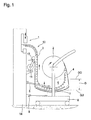
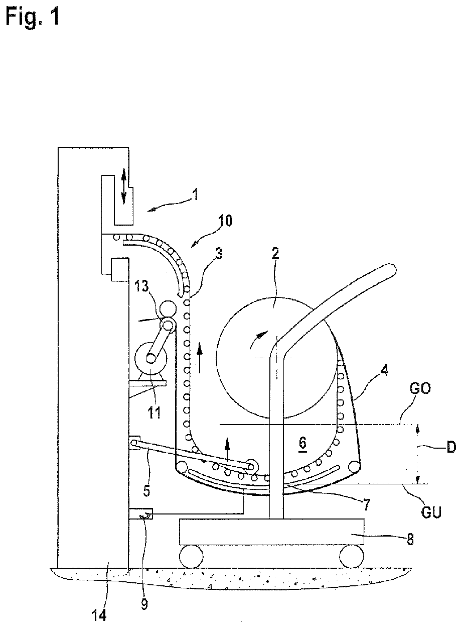
- Fig. 1 shows a crimping machine, comprising a driven by a first motor crimping tool 1 and a supply roll 2, on which a metallic contact element band 3 and a separation strip 4 deposited thereon are wound together to form a spiral, wherein the crimping train 1 assigned a collection device for clocked retraction of the contact element band 3 is.
- the sensor 5 can switch on the second motor 11 for a limited time, if the sag D of the contact element band 3 falls below an arbitrarily definable, lower limit GU, so that again a freely sagging, tension-free loop of the contact element band 3 is formed ,
- the extraction device 11 is in the design after Fig. 1 formed by a pair of take-off rollers 13 which are driven by the second motor 11 and pressed by the opposite sides of the separating strip 4 and are rotatable in opposite directions.
- the separating strip 4 is either fed directly from the gap of the withdrawal rollers 13 into a pneumatic extraction device or deposited in a waste container.
- the contact element tire 3 is withdrawn from the supply roll and transferred to the hanging storage 6. This is done independently of the drive of the crimping device.
- the second motor 11 forms part of the machine stand 14 of the crimping device and is actuated independently of the power stroke of the crimping tool 1 and only to fill the hanging memory 6.
- the switch-on frequency is considerably reduced. It is ensured in any case that no tensile forces can be transmitted to the crimping tool 1 via the contact element band 3.
- the second motor 11 is signal-controlled by the sensor 5 is actuated such that the contact element band 3 in the intermediate zone between the supply roll 2 and the crimping tool 1 is always free of tensile stresses. Due to the contact element band 3, therefore, no forces can be transmitted to the crimping tool 1, which are caused by the removal of the contact element band 3 from the supply roll 2.
- the contact element band 3 is accommodated in a suspended memory 6 in a freely hanging manner in the intermediate zone between the supply roll 2 and the crimping tool 1. It is very flexible and of very low weight in the relevant section. Vibration technology, the crimping tool 1 is therefore completely isolated from the supply roll.
- the sensor 5 is in the design after Fig. 1 formed by a pivotable measuring sensor, which is placed from above on the U - shaped sagging portion of the contact element band 3 and contacts the contact element band with a rotatable roller.
- the sensor 5 is configured to turn on the second motor 11 when the slack D of the contact element band 3 falls below an arbitrarily set lower limit value GU and turns off when the slack D exceeds an arbitrarily definable upper limit value GO.
- the senor 5 can also comprise at least one light barrier and / or a static contact for a control voltage.
- the sensor 5 may further be formed by a closing contact for a control voltage, wherein the closing contact comprises at least one input 7, which is arranged at the lowest point GU of the hanging memory 6 and may be formed by a metallic trough, with which the metallic and electrically conductive contact element strip 3 engages when filling the hanging memory 6.
- the output is formed by the contact element band 3, which can be lowered by the second motor 5 to the input 7.
- the forwarding of the signal thus obtained is expediently carried out via a plug-in contact 9, by which the trolley is connected to the crimping machine.
- the input 7 can thus be formed by a baffle, to which the contact element band 3 can be lowered by the second motor 11.
- a baffle has the advantage that snagging of the contact element band is excluded under all circumstances.
- Fig. 2 shows a design in which the extraction device 10 is formed for the separating strip 4 by a coil 12, on which the separating strip 4 wound and subsequently removed and disposed of.
- tensile forces are transmitted only indirectly via the separating strip in the supply roll 2 and not on the contact element band 3 itself. Due to the indirect transfer of the forces required to unwind the contact element band forces on the supply roll 2 by means of a deformable and limited stretchable strip 4 made of paper results in each of such a strong damping when switching the trigger device 11 in that no disturbing vibrations or forces can be transmitted to the crimping tool 1.
- the paper strip 4 presses in the introduction of tensile forces in the vertically projecting tabs and other vertically projecting parts and plastically deformed, which with an energy destruction is connected. Furthermore, a large length and a high extensibility of the separating strip has a positive effect on the avoidance of an undesired vibration transmission from the supply roll 2 to the crimping tool 1. In this case, it must be ensured that the tensile strength of the separating strip 4 is sufficiently large for reliable unwinding of the contact element strip 3 from the supply roll.
- the supply roll 2 with the contact element band 3 and parting strip 4 spirally wound thereon is rotatable in both designs and mounted in a freely displaceable carriage 8 in an easily exchangeable manner.
- the carriage includes only the storage for the supply roll 2, a handle for facilitating moving and the formed by a curved baffle, electrical input 7 of the sensor 5 and a plug contact element of the connector 9, which is engageable with a mating contact socket of the crimping machine ,
- the cart is accordingly very inexpensive to produce and easy to move manually. It can be stored in large numbers in a warehouse, which also saves the need to manually transport heavy supply rolls 2 and insert them manually into the various crimping machines.
Landscapes
- Engineering & Computer Science (AREA)
- Manufacturing & Machinery (AREA)
- Manufacturing Of Electrical Connectors (AREA)
- Controlling Rewinding, Feeding, Winding, Or Abnormalities Of Webs (AREA)
Abstract
Ein Crimpautomat, umfassend ein durch einen ersten Motor angetriebenes Crimpwerkzeug (1) und eine Vorratsrolle (2), auf der ein metallisches Kontaktelementband (3) und ein darauf abgelegter Trennstreifen (4) gemeinsam zu einer Spirale aufgewickelt sind, wobei dem Crimpwerkzug (1) eine Einzugsvorrichtung zum Einziehen des Kontaktelementbandes (3) in das Crimpwerkzeug (1) zugeordnet ist. Zum Abziehen des Kontaktelementbandes (3) von der Vorratsrolie (2) ist ein signalbetätigbarer, zweiter Motor (11) und ein Sensor (5) vorgesehen, der den zweiten Motor (11) so betätigt, dass das Kontaktelementband (3) in der Zwischenzone zwischen der Vorratsrolle (2) und dem Crimpwerkzeug (1) frei von Zugspannungen ist.
Description
Die Erfindung betrifft einen Crimpautomaten, umfassend ein durch einen ersten Motor angetriebenes Crimpwerkzeug und eine Vorratsrolle, auf der ein metallisches Kontaktelementband und ein darauf abgelegter Trennstreifen gemeinsam zu einer Spirale aufgewickelt sind, wobei dem Crimpwerkzeug eine Einzugsvorrichtung zum Einziehen des Kontaktelementbandes in das Crimpwerkzeug zugeordnet ist.The invention relates to a crimping machine comprising a crimping tool driven by a first motor and a supply roll on which a metallic contact element strip and a separating strip deposited thereon are wound together to form a spiral, wherein the crimping tool is assigned a collection device for drawing the contact element strip into the crimping tool.
Eine solcher Crimpautomat ist aus der
Bei der Verarbeitung eines Kontaktelementbandes in einem Crimpwerkzeug werden die darin enthaltenen und durch einen Tiefziehprozess erzeugten Crimpkontakte durch plastische Verformung an Kabelenden festgelegt und zugleich von dem Kontaktelementband abgestanzt. Dies ist mit der Erzeugung von erheblichen Schwingungen verbunden.When processing a contact element band in a crimping tool, the crimp contacts contained therein and produced by a deep-drawing process are determined by plastic deformation at cable ends and at the same time are punched by the contact element band. This is associated with the generation of significant vibrations.
Beim Aufwickeln eines Kontaktelementbandes auf eine Vorratsrolle ergeben sich erheblichen Schwierigkeiten, weil die von dem Kontaktelementband vertikal vorstehenden Crimpfahnen und Steckverbinder der einzelnen Kontaktelemente beim Aufwickeln nicht deformiert werden dürfen und dazu neigen, sich mit einander zu verhaken. Ein Kontaktelementband kann daher nur unter Zwischenfügung eines Trennstreifens aus glattem Papier und nur lose auf eine Vorratsrolle aufgewickelt werden. Es ist von großem Gewicht mit der Folge, dass sich die fertige Rolle bei der späteren Lagerung und dem Transport verformt und dass sich eine Unwuchtigkeit einstellt. Außerdem können sich die vorstehenden Teile ineinander und in dem Trennsteifen verhaken. Das führt beim späteren Abspulen zu Problemen. Das Abspulen wird zusätzlich dadurch erschwert, dass In einem Crimpautomaten das Abspulen nicht kontinuierlich sondern im Arbeitstakt des Crimpwerkzeuges getaktet und somit diskontinuierlich erfolge, Das Abziehen des Kontaktelementbandes von der Vorratsrolle setzt daher bei einem jeden Crimpvorgang ein getaktetes Beschleunigen und Auslaufen der schweren Vorratsrolle in kleinsten Schritten voraus. Die dadurch generierten Schwingungen können sich mit den üblichen Unwuchten der Vorratsrolle und dem gegenseitigen Verhaken der Crimpkontaktzemente des Kontaktelementbandes derart ungünstig überlagern, dass die Crimpqualität verschlechtert wird. Es ist daher bei der bekannten Bauform unverzichtbar, die Vorratsrolle in Bezug auf das Crimpwerkzeug starr verriegelt festzulegen. Dies ist mit einem zusätzlichen technischem Aufwand verbunden sowie mit einem hohen Bedienungsaufwand während der Benutzung.When winding a contact element band on a supply roll, considerable difficulties arise because the vertically protruding from the contact element band Crimpfahnen and connectors of the individual contact elements during winding must not be deformed and tend to get caught with each other. A contact element band can therefore be wound only with the interposition of a separating strip of smooth paper and only loosely on a supply roll. It is of great importance, with the consequence that the finished roll deforms during later storage and transport and that an unevenness sets in. In addition, the protruding parts can get caught in each other and in the separating stiffener. This leads to later unwinding problems. The unwinding is made more difficult by the fact that in a crimping machine the unwinding is not continuously but clocked in the working cycle of the crimping tool and thus discontinuous successes, the withdrawal of the contact element band from the supply roll therefore requires in each crimping a clocked acceleration and leakage of the heavy supply roll in the smallest steps. The vibrations generated thereby can interfere with the usual imbalances of the supply roll and the mutual entanglement of the crimp contact cements of the contact element band so unfavorably that the crimp quality is deteriorated. It is therefore indispensable in the known design to set the supply roll rigidly locked with respect to the crimping tool. This is associated with an additional technical effort and with a high operating effort during use.
Der Erfindung liegt die Aufgabe zur Grunde, einen Crimpautomaten der Eingangs genannten Art derart weiterzuentwickeln, dass die zur Verfügung stehenden Kontaktelementbänder problemlos und in hoher Crimpqualität verarbeitet werden können, dass ein Austausch der Vorratsrollen erleichtert möglich und eine starre Verriegelung der Lagerung der Vorratsrollen nicht mehr nötig ist.The invention has the object of further developing a crimping machine of the type mentioned in such a way that the available contact element bands can be processed easily and in high crimp quality that facilitates the replacement of the supply rolls possible and a rigid locking the storage of the supply rolls no longer necessary is.
Diese Aufgabe wird erfindungsgemäß mit den kennzeichnenden Merkmalen von Anspruch 1 gelöst. Auf vorteilhafte Ausgestaltungen nehmen die Unteransprüche Bezug.This object is achieved with the characterizing features of
Bei der erfindungsgemäßen Vorrichtung ist zur Lösung dieser Aufgabe ein Crimpautomat vorgesehen, umfassend ein durch einen ersten Motor angetriebenes Crimpwerkzeug und eine Vorratsrolle, auf der ein metallisches Kontaktelementband und ein darauf abgelegter Trennstreifen gemeinsam zu einer Spirale aufgewickelt sind, wobei dem Crimpwerkzug eine Einzugsvorrichtung zum Einziehen des Kontaktelementbandes in das Crimpwerkzeug zugeordnet ist. Dabei ist es nunmehr vorgesehen, dass zum Abziehen des Kontaktelementbandes von der Vorratsrolle ein signalbetätigbarer, zweiter Motor vorgesehen ist und dass ein Sensor vorgesehen ist, der den zweiten Motor so betätigt, dass das Kontaktelementband in der Zwischenzone zwischen der Vorratsrolle und dem Crimpwerkzeug frei von Zugspannungen ist. Über das Kontaktelementband können daher keine Zug- oder Beschleunigungskräfte auf das Crimpwerkzeug übertragen werden, die das damit im Crimpprozess erzielte Arbeitsergebnis nachteilig belasten. Eine verriegelte Zuordnung der Lagerung der Vorratsrollen ist daher entbehrlich und der Austausch einer leeren durch eine volle Vorratsrolle erheblich vereinfacht.In the apparatus according to the invention an automatic crimping machine is provided to solve this problem, comprising a driven by a first motor crimping tool and a supply roll on which a metallic contact element band and a separation strip deposited thereon are wound together to form a spiral, the Crimpwerkzug a Feed device is assigned for pulling the contact element band in the crimping tool. It is now envisaged that for subtracting the contact element band of the supply roll a signal-actuated, second motor is provided and that a sensor is provided which actuates the second motor so that the contact element band in the intermediate zone between the supply roll and the crimping tool free of tensile stresses is. Therefore no tensile or acceleration forces can be transmitted to the crimping tool via the contact element band, which adversely affect the work result thus achieved in the crimping process. A locked allocation of the storage of the supply rolls is therefore unnecessary and the replacement of an empty by a full supply roll considerably simplified.
Die Übertragung von Zugkräften wird besonders zuverlässig unterdrückt, wenn das Kontaktelementband in der Zwischenzone zwischen der Vorratsrolle, und dem Crimpwerkzeug locker U - förmig durchhängend in einem Hängespeicher aufgenommen ist. Ein Sensor schaltet den zweiten Motor dabei zeitlich begrenzt nur dann ein, wenn der Durchhang D des Kontaktelementband einen willkürlich festlegbaren, unteren Grenzwert GU unterschreitet. Die zeitliche Grenze, bis zu der der zweite Motor das Kontaktelementband dann von der Vorratsrolle abzieht, lässt sich empirisch leicht ermitteln, Die Ausführung ist besonders einfach aufgebaut.The transmission of tensile forces is suppressed particularly reliably when the contact element strip is loosely received in a hanging storage in the intermediate zone between the supply roll and the crimping tool in a U-shaped manner. A sensor activates the second motor for a limited time only when the sag D of the contact element band falls below an arbitrarily definable, lower limit GU. The time limit up to which the second motor then subtracts the contact element band from the supply roll can be easily determined empirically. The design is particularly simple.
Es besteht auch die Möglichkeit, die Ausführung so zu gestalten, dass der Sensor den zweiten Motor einschaltet, wenn der Durchhang D des Kontaktelementband einen willkürlich festlegbaren, unteren Grenzwert GU unterschreitet und aus, wenn der Durchhang D einen willkürlich festlegbaren, oberen Grenzwert GO überschreitet. Die Grenzwerte sind auch dabei empirisch leicht ermittelbar und maßgeblich von dem verfügbaren Raum bestimmt. Insgesamt genügt in den meisten Fällen ein maximaler Durchhang D von 50 bis 200 mm, um ein gutes Arbeitsergebnis zu erzielen unter Vermeidung unnötig zahlreicher Betätigungsvorgänge des zweiten Motors.It is also possible to make the design such that the sensor turns on the second motor when the sag D of the contact element band falls below an arbitrarily set lower limit value GU and off when the slack D exceeds an arbitrarily definable upper limit value GO. The limits are also empirically easily determined and largely determined by the available space. Overall, in most cases, a maximum sag D of 50 to is sufficient 200 mm to achieve a good work result while avoiding unnecessarily numerous operations of the second motor.
Der Sensor kann zumindest eine Lichtschranke und/oder einen Berührungskontakt für eine Steuerspannung umfassen.The sensor may comprise at least one light barrier and / or a touch contact for a control voltage.
Nach einer besonders kostengünstigen und robusten Ausgestaltung ist es vorgesehen, dass der Sensor durch einen Schließkontakt für eine Steuerspannung gebildet ist und dass der Schließkontakt zumindest einen Eingang umfasst, der an der tiefsten Stelle des Hängespeichers angeordnet ist und zumindest einen Ausgang, der durch das Kontaktelementband gebildet ist, wobei das Kontaktelementband durch den zweiten Motor auf den Eingang absenkbar ist. Die Steuerspannung, dabei handelt es sich zur Vermeidung von unnötigen Unfallrisiken um eine Niederspannung, wird zweckmäßig durch das Crimpwerkzeug an das Kontaktelementband angelegt und am durch einen Kontakt abgenommen, der mit dem Kontaktelementband in Berührung gelangt, wenn dieses den tiefsten Punkt im Hängespeicher erreicht. Für die Weiterleitung des dabei erhaltenen und zur Steuerung des dem zweiten Motors benötigten Signals kann eine lösbare Steckverbindung vorgesehen sein, die leicht herstellbar ist. Eine Ansteuerung des zweiten Motors mit dem dazu benötigten Signal kann so erreicht werden, ohne dass sich für den Anwender ein zusätzlicher Arbeitsaufwand ergibt.According to a particularly inexpensive and robust embodiment, it is provided that the sensor is formed by a closing contact for a control voltage and that the closing contact comprises at least one input which is arranged at the lowest point of the hanging memory and at least one output formed by the contact element band is, wherein the contact element band is lowered by the second motor to the input. The control voltage, it is to avoid unnecessary accident risks to a low voltage is suitably applied by the crimping tool to the contact element band and removed by a contact that comes into contact with the contact element band when it reaches the lowest point in the hanging storage. For the forwarding of the signal obtained thereby and for controlling the signal required for the second motor, a releasable plug connection can be provided which is easy to manufacture. A control of the second motor with the required signal can thus be achieved without resulting in additional work for the user.
Der Eingang der Steuerung kann bei einer solchen Bauform durch ein Leitblech gebildet sein, auf das das Kontaktelementband durch den zweiten Motor absenkbar ist und das dabei im abgesenkten Zustand den benötigten Kontakt herstellt. Liegt ein Kontakt an, dann signalisiert das einen vollen Hängespeicher und die Abschaltung des zweiten Motors. Wird der Kontakt unterbrochen, dann signalisiert das im einfachsten Fall einen leeren Hängespeicher und er zweite Motor wird erneut eingeschaltet bis sich ein neuer Kontakt ergibt. Durch Verzögerungsschaltungen, die den aktuellen Betriebszustand und/oder Verbrauch des Crimpwerkzeuges mit berücksichtigen, lassen sich damit trotz einfachsten Aufbaus der Schaltung unnötig häufige Schaltvorgänge vermeiden.The input of the controller may be formed in such a design by a baffle on which the contact element band can be lowered by the second motor and thereby produces the required contact in the lowered state. If there is a contact, this signals a full suspension memory and the shutdown of the second motor. If the contact is interrupted, this signals in the simplest case an empty hanging storage and the second motor is turned on again until a new contact results. By Delay circuits, which take into account the current operating state and / or consumption of the crimping tool, thus avoid unnecessary frequent switching operations despite the simplest construction of the circuit.
Der zweite Motor kann zum Abziehen des Kontaktelementbandes von der Vorratsrolle mit einer Abzugsvorrichtung für den Trennstreifen zusammenwirken. Während das Kontaktelementband eine unebene Oberfläche und je nach Bauform der Crimpkontaktelemente ganz unterschiedliche Dimensionen und Formen haben und demgemäss schwierig sicher und beschädigungsfrei mit standardisierten Mitteln zu ergreifen und zu transportieren ist, besteht der Trennsteifen zumeist aus einem Hartpapier, das mit Rollen leicht und sicher erfassbar und transportierbar ist, das ferner nicht am Produkt verbleibt und das insoweit ohnehin aus der Verarbeitungszone entfernt werden muss. Das Kontaktelementband wird daher im Sinn der Erfindung bevorzugt durch Abziehen des Trennstreifens von der Vorratsrolle abgespult.The second motor can cooperate for removing the contact element band from the supply roll with a withdrawal device for the separating strip. While the contact element band have an uneven surface and, depending on the design of the Crimpkontaktelemente completely different dimensions and shapes and accordingly difficult to seize and transport safely and damage-free with standardized means and transport, the release of most of a hard paper that easily and safely detected with roles and can be transported, which also does not remain on the product and in this respect anyway must be removed from the processing zone. The contact element band is therefore preferably unwound in the sense of the invention by removing the separating strip from the supply roll.
Die Abzugsvorrichtung kann durch eine Spule gebildet sein, auf die der Trennstreifen aufwickelbar ist. Die Spule kann dabei aus einer Wegwerfhülse aus Karton oder eine Spannhülse bestehen, die nach dem Aufwickeln des Trennstreifens aus diesem herausgezogen und anschließend wieder verwendet werden kann.The withdrawal device may be formed by a coil, on which the separating strip can be wound up. The coil may consist of a disposable sleeve made of cardboard or a clamping sleeve, which can be pulled out after the winding of the separating strip from this and then used again.
Die Abzugsvorrichtung kann auch durch ein Paar Abzugsrollen gebildet sein, die von den einander gegenüberliegenden Seiten an den Trennstreifen anpressbar und gegensinnig rotierbar sind, um den dazwischen eingefügten Trennstreifen abzuziehen und in einen Abfallbehälter oder einen pneumatischen Stetigförderer einzuspeisen.The take-off device may also be formed by a pair of take-off rollers which are pressable and counterrotatable from the opposite sides of the parting strip to withdraw the parting strip interposed therebetween and feed it into a waste container or a pneumatic continuous conveyor.
Die Vorratsrolle kann austauschbar in einem frei verschiebbaren Wagen gelagert sein. Dies bietet die Möglichkeit, eine Vielzahl unterschiedlicher Kontaktelementbänder zu bevorraten und nach Bedarf aus dem Lager zu holen, an einen Crimpautomaten anzuschließen und zu verarbeiteten.The supply roll can be stored interchangeably in a freely movable carriage. This provides the ability to stockpile a variety of different contact element bands and get out of stock as needed, connect to a crimping machine and processed.
Der zweite Motor und gegebenenfalls die Abzugsvorrichtung können dabei einen Bestandteil des Crimpautomaten bilden und stationär gelagert sein. Sie werden immer wider verwendet und es ist daher nicht erforderlich, den Wagen mit der Vorratsrolle damit zu belasten und zu verteuern.The second motor and optionally the triggering device can form part of the crimping machine and be stored stationary. They are always used against and it is therefore not necessary to burden the car with the supply roll and make it more expensive.
Mehrere Ausführungsbeispiele der Erfindung sind in der Zeichnung dargestellt und in der nachfolgenden Beschreibung näher erläutert. Es zeigen:
-
Fig. 1 eine erste Bauform, bei der eine auf einem Wagen gelagerte Vorratsrolle an einem Crimpautomaten in Arbeitsposition gebracht ist. Die Abzugsvorrichtung für das Kontaktelementband ist durch ein Paar Reibrolle gebildet, die beiderseits an den Trennstreifen angepresst sind und durch dessen Abzug ein Abspulen des Kontaktelementbandes bewirken. -
Fig. 2 eine zweite Bauform ähnlichFig. 1 , bei der die Abzugsvorrichtung für das Kontaktelementband durch eine Spule gebildet ist.
-
Fig. 1 a first design in which a stored on a carriage supply roll is placed on a crimping machine in working position. The take-off device for the contact element band is formed by a pair of friction roller, which are pressed on both sides of the separating strip and cause by its deduction unwinding of the contact element band. -
Fig. 2 similar to a second designFig. 1 in which the take-off device for the contact element band is formed by a coil.
In den Zeichnungen bezeichnen übereinstimmende Bezugszeichen übereinstimende Gegenstände.In the drawings, like reference characters designate corresponding items.
Zum Abziehen des Kontaktelementbandes 3 von der Vorratsrolle 2 kann der Sensor 5 den zweiten Motor 11 zeitlich begrenzt einschalten, wenn der Durchhang D des Kontaktelementband 3 einen willkürlich festlegbaren, unteren Grenzwert GU unterschreitet, so dass erneut eine frei durchhängende, spannungsfreie Schlaufe des Kontaktelementbandes 3 entsteht.To remove the contact element band 3 from the
Die Abzugsvorrichtung 11 ist bei der Bauform nach
Der zweite Motor 11 bildet einen Bestandteil des Maschinenständers 14 der Crimpvorrichtung und wird unabhängig vom Arbeitstakt des Crimpwerkzeuges 1 und nur zum Auffüllen des Hängespeichers 6 betätigt. Die Einschalthäufigkeit ist dadurch erheblich vermindert. Sichergestellt ist in jedem Falle, dass über das Kontaktelementband 3 keine Zugkräfte auf das Crimpwerkzeug 1 übertragen werden können.The
Der zweite Motor 11 wird signalgesteuert von dem Sensor 5 derart betätigt, dass das Kontaktelementband 3 in der Zwischenzone zwischen der Vorratsrolle 2 und dem Crimpwerkzeug 1 immer frei von Zugspannungen ist. Durch das Kontaktelementband 3 können daher keine Kräfte auf das Crimpwerkzeug 1 übertragen werden, die durch das Abziehen des Kontaktelementbandes 3 von der Vorratsrolle 2 verursacht sind.The
Das Kontaktelementband 3 ist in der Zwischenzone zwischen der Vorratsrolle 2 und dem Crimpwerkzeug 1 U - förmig frei durchhängend in einem Hängespeicher 6 aufgenommen. Es ist sehr flexibel und in dem betreffenden Abschnitt von sehr geringem Gewicht. Schwingungstechnisch ist das Crimpwerkzeug 1 daher vollständig von der Vorratsrolle isoliert.The contact element band 3 is accommodated in a suspended
Der Sensor 5 ist bei der Bauform nach
Der Sensor 5 kann als Alternative zu einem schwenkbaren oder beweglichen Messfühler auch zumindest eine Lichtschranke und/oder einen statischen Berührungskontakt für eine Steuerspannung umfassen.As an alternative to a pivotable or movable measuring sensor, the
Der Sensor 5 kann ferner durch einen Schließkontakt für eine Steuerspannung gebildet sein, wobei der Schließkontakt zumindest einen Eingang 7 umfasst, der an der tiefsten Stelle GU des Hängespeichers 6 angeordnet ist und durch eine metallische Wanne gebildet sein kann, mit der der metallische und elektrisch leitende Kontaktelementstreifen 3 beim Auffüllen des Hängespeichers 6 in Eingriff gelangt. Der Ausgang ist dabei durch das Kontaktelementband 3 gebildet, das durch den zweiten Motor 5 auf den Eingang 7 absenkbar ist. Die Weiterleitung des so gewonnenen Signals erfolgt zweckmäßig über einen Steckkontakt 9, durch den der Transportwagen an den Crimpautomaten angeschlossen wird.The
Der Eingang 7 kann somit durch ein Leitblech gebildet ist, auf das das Kontaktelementband 3 durch den zweiten Motor 11 absenkbar ist. Ein solches Leitblech bietet den Vorteil, dass ein Verhaken des Kontaktelementbandes unter allen Umständen ausgeschlossen ist.The
Der Trennstreifen ist sehr viel flexibler und dehnbarer als das Kontaktelementband 3. Durch die indirekte Überbertragung der zum Abspulen des Kontaktelementbandes erforderlichen Kräfte auf die Vorratsrolle 2 mittels eines verformbaren und begrenzt dehnbaren Trennstreifes 4 aus Papier ergibt sich beim Einschalten der Abzugsvorrichtung 11 jeweils eine so starke Dämpfung, dass keine störenden Schwingungen oder Kräfte auf das Crimpwerkzeug 1 übertragen werden können.
Due to the indirect transfer of the forces required to unwind the contact element band forces on the
Dabei ist es auch von Bedeutung, dass sich der Papierstreifen 4 bei der Einleitung von Zugkräften in die vertikal vorstehenden Kontaktfahnen und andere vertikal vorstehende Teile eindrückt und plastisch verformt, was mit einer Energievernichtung verbunden ist. Ferner wirkt sich eine große Länge und eine große Dehnbarkeit des Trennstreifens positiv auf die Vermeidung einer unerwünschten Schwingungsübertragung von der Vorratsrolle 2 auf das Crimpwerkzeug 1 aus. Hierbei ist sicher zu stellen, dass die Zugfestigkeit des Trennstreifens 4 hinreichend groß für ein sicheres Abspulen des Kontaktelementbandes 3 von der Vorratsrolle ist.It is also important that the paper strip 4 presses in the introduction of tensile forces in the vertically projecting tabs and other vertically projecting parts and plastically deformed, which with an energy destruction is connected. Furthermore, a large length and a high extensibility of the separating strip has a positive effect on the avoidance of an undesired vibration transmission from the
Die Vorratsrolle 2 mit dem spiralig darauf aufgespulten Kontaktelementband 3 und Trennstreifen 4 ist bei beiden Bauformen rotierbar und leicht austauschbar in einem frei verschiebbaren Wagen 8 gelagert.The
Der Wagen umfasst dabei nur die Lagerung für die Vorratsrolle 2, einen Griff zum erleichterten Verschieben sowie den durch ein gewölbtes Leitblech gebildeten, elektrischen Eingang 7 des Sensors 5 und ein Steckkontaktelement der Steckverbindung 9, das mit einer dazu passenden Kontaktbuchse des Crimpautomaten in Eingriff bringbar ist. Der Wagen ist demgemäss sehr kostengünstig herstellbar und leicht manuell verschiebbar. Er kann in einem Lager in großer Stückzahl bereitgehalten werden, was es auch erspart, schwere Vorratsrollen 2 manuell zu transportieren und manuell in die verschiedenen Crimpautomaten einzulegen.The carriage includes only the storage for the
Der Sensor 5, der zweite Motor 11 und gegebenenfalls die Abzugsvorrichtung 10 bilden demgegenüber zweckmäßig einen Bestandteil des Crimpautomaten und können stationär gelagert sein. Es ist daher auch nicht erforderlich, sie in einem jedem Wagen separat verfügbar zu haben, sie manuell zu transportieren und jeweils zur inbetriebnahme elektrisch an das Hoch- und Niederspannungsnetz des Crimpautomaten neu anzuschließen.The
Claims (13)
Priority Applications (1)
| Application Number | Priority Date | Filing Date | Title |
|---|---|---|---|
| PL09171078T PL2169783T3 (en) | 2008-09-25 | 2009-09-23 | Automatic crimper |
Applications Claiming Priority (1)
| Application Number | Priority Date | Filing Date | Title |
|---|---|---|---|
| DE102008049021A DE102008049021B4 (en) | 2008-09-25 | 2008-09-25 | crimping machine |
Publications (3)
| Publication Number | Publication Date |
|---|---|
| EP2169783A2 true EP2169783A2 (en) | 2010-03-31 |
| EP2169783A3 EP2169783A3 (en) | 2013-04-17 |
| EP2169783B1 EP2169783B1 (en) | 2014-09-17 |
Family
ID=41338700
Family Applications (1)
| Application Number | Title | Priority Date | Filing Date |
|---|---|---|---|
| EP09171078.0A Active EP2169783B1 (en) | 2008-09-25 | 2009-09-23 | Automatic crimper |
Country Status (4)
| Country | Link |
|---|---|
| EP (1) | EP2169783B1 (en) |
| DE (1) | DE102008049021B4 (en) |
| ES (1) | ES2524467T3 (en) |
| PL (1) | PL2169783T3 (en) |
Cited By (1)
| Publication number | Priority date | Publication date | Assignee | Title |
|---|---|---|---|---|
| DE202011107870U1 (en) | 2011-11-14 | 2013-02-18 | Schäfer Werkzeug- und Sondermaschinenbau GmbH | Variable feeder for a crimping unit |
Citations (2)
| Publication number | Priority date | Publication date | Assignee | Title |
|---|---|---|---|---|
| US20060172610A1 (en) | 2005-02-01 | 2006-08-03 | Keisuke Sakai | Method and apparatus for terminal row insert molding |
| WO2006136930A1 (en) | 2005-06-23 | 2006-12-28 | Schleuniger Holding Ag | Crimping machine for different crimping and pressing processes, in particular for cable assembly |
Family Cites Families (7)
| Publication number | Priority date | Publication date | Assignee | Title |
|---|---|---|---|---|
| US4363167A (en) * | 1980-08-11 | 1982-12-14 | Amp Incorporated | Method of terminating leading ends of a plurality of wires |
| JPS6428154A (en) * | 1987-07-20 | 1989-01-30 | Japan Aviation Electron | Chained part taking-up device |
| JP2592678Y2 (en) * | 1993-06-11 | 1999-03-24 | 住友電装株式会社 | Terminal band supply device |
| JP3653934B2 (en) * | 1997-06-09 | 2005-06-02 | 住友電装株式会社 | Terminal reel deformation correction device |
| FR2820601A1 (en) * | 2001-01-23 | 2002-08-09 | Fci Automotive France | CONNECTOR FEEDING DEVICE AND CRIMPING STATION PROVIDED WITH SUCH A DEVICE |
| US6530511B2 (en) * | 2001-02-13 | 2003-03-11 | Medallion Technology, Llc | Wire feed mechanism and method used for fabricating electrical connectors |
| DE102004057818B3 (en) * | 2004-12-01 | 2006-08-03 | Schäfer Werkzeug- und Sondermaschinenbau GmbH | Device for semi- or fully automatic attachment of a contact element to a cable end |
-
2008
- 2008-09-25 DE DE102008049021A patent/DE102008049021B4/en not_active Expired - Fee Related
-
2009
- 2009-09-23 PL PL09171078T patent/PL2169783T3/en unknown
- 2009-09-23 ES ES09171078.0T patent/ES2524467T3/en active Active
- 2009-09-23 EP EP09171078.0A patent/EP2169783B1/en active Active
Patent Citations (2)
| Publication number | Priority date | Publication date | Assignee | Title |
|---|---|---|---|---|
| US20060172610A1 (en) | 2005-02-01 | 2006-08-03 | Keisuke Sakai | Method and apparatus for terminal row insert molding |
| WO2006136930A1 (en) | 2005-06-23 | 2006-12-28 | Schleuniger Holding Ag | Crimping machine for different crimping and pressing processes, in particular for cable assembly |
Cited By (3)
| Publication number | Priority date | Publication date | Assignee | Title |
|---|---|---|---|---|
| DE202011107870U1 (en) | 2011-11-14 | 2013-02-18 | Schäfer Werkzeug- und Sondermaschinenbau GmbH | Variable feeder for a crimping unit |
| EP2592703A2 (en) | 2011-11-14 | 2013-05-15 | Schäfer Werkzeug- und Sondermaschinenbau GmbH | Variable feed device for a crimping unit |
| EP2592703A3 (en) * | 2011-11-14 | 2014-01-15 | Schäfer Werkzeug- und Sondermaschinenbau GmbH | Variable feed device for a crimping unit |
Also Published As
| Publication number | Publication date |
|---|---|
| EP2169783B1 (en) | 2014-09-17 |
| ES2524467T3 (en) | 2014-12-09 |
| DE102008049021B4 (en) | 2013-10-24 |
| EP2169783A3 (en) | 2013-04-17 |
| PL2169783T3 (en) | 2015-03-31 |
| DE102008049021A1 (en) | 2010-04-01 |
Similar Documents
| Publication | Publication Date | Title |
|---|---|---|
| EP2873499B1 (en) | Cutting device for cutting a thin and adhesive belt, in particular a cord belt | |
| EP2738886A1 (en) | Method and assembly for producing a crimped connection | |
| EP2399715A1 (en) | Depositing and use separation station for a sheet punching press | |
| EP2666216A2 (en) | Arrangement and method for locking an automatic reeling mechanism of a charging cable for an electric vehicle | |
| WO2014166511A1 (en) | Lift table and conveyor system | |
| EP3666700A1 (en) | Device for winding and winding replacement for web-shaped material and method for same | |
| EP2592703B1 (en) | Variable feed device for a crimping unit | |
| EP2985093A1 (en) | Blind riveting apparatus and method for setting a blind rivet | |
| DE102011083400B4 (en) | Method and storage facility with overload detection | |
| EP2169783B1 (en) | Automatic crimper | |
| DE102004033548A1 (en) | Lift station for car bodywork in lacquering plant comprises platform which is lifted up frame by cables, accumulator mounted in platform providing energy to operate conveyor below it | |
| EP1640273B1 (en) | Coiling device for removing cut binding material | |
| EP3060484B1 (en) | Apparatus and method for changing paper rolls in a labelling machine | |
| DE202008018389U1 (en) | crimping machine | |
| DE102012107161B4 (en) | Apparatus and method for producing an energy storage cell | |
| AT13149U1 (en) | Foil wrapping machine | |
| EP1975967A1 (en) | Switching device with a device for wireless transmission of information on the status of a device | |
| EP1820583A1 (en) | Method and device for producing metal tape wound into a coil | |
| DE102018102182A1 (en) | Media drawer for a media processing device and media processing device | |
| DE112022005626T5 (en) | ELECTRICALLY OPERATED DEVICE, ELECTROMECHANICAL CONVERSION DEVICE, ELECTRICAL POWER STORAGE DEVICE. ELECTRICAL POWER SUPPLY SYSTEM, METHOD FOR CONTROLLING AN ELECTRICAL POWER SUPPLY SYSTEM, PROGRAM AND STORAGE MEDIUM | |
| EP3819036B1 (en) | Device for coiling sheet-like material | |
| AT522407B1 (en) | Output device for outputting a flat product in web form | |
| DE102010016649A1 (en) | Voltage converter, has fixed stops limiting pivotable region of lever of operating element, and lock pin that is reciprocally movable, so that lever does not tiltable and is interposed between fixed stops and lock pin | |
| DE102008009166A1 (en) | Contacting system for battery-powered industrial trucks | |
| EP1746067B1 (en) | Lift station in a surface treatment plant. |
Legal Events
| Date | Code | Title | Description |
|---|---|---|---|
| PUAI | Public reference made under article 153(3) epc to a published international application that has entered the european phase |
Free format text: ORIGINAL CODE: 0009012 |
|
| 17P | Request for examination filed |
Effective date: 20090923 |
|
| AK | Designated contracting states |
Kind code of ref document: A2 Designated state(s): AT BE BG CH CY CZ DE DK EE ES FI FR GB GR HR HU IE IS IT LI LT LU LV MC MK MT NL NO PL PT RO SE SI SK SM TR |
|
| AX | Request for extension of the european patent |
Extension state: AL BA RS |
|
| PUAL | Search report despatched |
Free format text: ORIGINAL CODE: 0009013 |
|
| AK | Designated contracting states |
Kind code of ref document: A3 Designated state(s): AT BE BG CH CY CZ DE DK EE ES FI FR GB GR HR HU IE IS IT LI LT LU LV MC MK MT NL NO PL PT RO SE SI SK SM TR |
|
| AX | Request for extension of the european patent |
Extension state: AL BA RS |
|
| RIC1 | Information provided on ipc code assigned before grant |
Ipc: H01R 43/055 20060101AFI20130314BHEP |
|
| RBV | Designated contracting states (corrected) |
Designated state(s): AT BE BG CH CY CZ DE DK EE ES FI FR GB GR HR HU IE IS IT LI LT LU LV MC MK MT NL NO PL PT RO SE SI SK SM TR |
|
| GRAP | Despatch of communication of intention to grant a patent |
Free format text: ORIGINAL CODE: EPIDOSNIGR1 |
|
| INTG | Intention to grant announced |
Effective date: 20140331 |
|
| GRAS | Grant fee paid |
Free format text: ORIGINAL CODE: EPIDOSNIGR3 |
|
| GRAA | (expected) grant |
Free format text: ORIGINAL CODE: 0009210 |
|
| AK | Designated contracting states |
Kind code of ref document: B1 Designated state(s): AT BE BG CH CY CZ DK EE ES FI FR GB GR HR HU IE IS IT LI LT LU LV MC MK MT NL NO PL PT RO SE SI SK SM TR |
|
| RBV | Designated contracting states (corrected) |
Designated state(s): AT BE BG CH CY CZ DK EE ES FI FR GB GR HR HU IE IS IT LI LT LU LV MC MK MT NL NO PL PT RO SE SI SK SM TR |
|
| REG | Reference to a national code |
Ref country code: DE Ref legal event code: R108 Ref country code: GB Ref legal event code: FG4D Free format text: NOT ENGLISH |
|
| REG | Reference to a national code |
Ref country code: CH Ref legal event code: EP |
|
| REG | Reference to a national code |
Ref country code: IE Ref legal event code: FG4D Free format text: LANGUAGE OF EP DOCUMENT: GERMAN |
|
| REG | Reference to a national code |
Ref country code: AT Ref legal event code: REF Ref document number: 688065 Country of ref document: AT Kind code of ref document: T Effective date: 20141015 |
|
| REG | Reference to a national code |
Ref country code: DE Ref legal event code: R108 Effective date: 20140917 |
|
| REG | Reference to a national code |
Ref country code: RO Ref legal event code: EPE |
|
| REG | Reference to a national code |
Ref country code: ES Ref legal event code: FG2A Ref document number: 2524467 Country of ref document: ES Kind code of ref document: T3 Effective date: 20141209 |
|
| REG | Reference to a national code |
Ref country code: CH Ref legal event code: NV Representative=s name: SCHNEIDER FELDMANN AG PATENT- UND MARKENANWAEL, CH |
|
| PG25 | Lapsed in a contracting state [announced via postgrant information from national office to epo] |
Ref country code: FI Free format text: LAPSE BECAUSE OF FAILURE TO SUBMIT A TRANSLATION OF THE DESCRIPTION OR TO PAY THE FEE WITHIN THE PRESCRIBED TIME-LIMIT Effective date: 20140917 Ref country code: GR Free format text: LAPSE BECAUSE OF FAILURE TO SUBMIT A TRANSLATION OF THE DESCRIPTION OR TO PAY THE FEE WITHIN THE PRESCRIBED TIME-LIMIT Effective date: 20141218 Ref country code: SE Free format text: LAPSE BECAUSE OF FAILURE TO SUBMIT A TRANSLATION OF THE DESCRIPTION OR TO PAY THE FEE WITHIN THE PRESCRIBED TIME-LIMIT Effective date: 20140917 Ref country code: LT Free format text: LAPSE BECAUSE OF FAILURE TO SUBMIT A TRANSLATION OF THE DESCRIPTION OR TO PAY THE FEE WITHIN THE PRESCRIBED TIME-LIMIT Effective date: 20140917 Ref country code: NO Free format text: LAPSE BECAUSE OF FAILURE TO SUBMIT A TRANSLATION OF THE DESCRIPTION OR TO PAY THE FEE WITHIN THE PRESCRIBED TIME-LIMIT Effective date: 20141217 |
|
| REG | Reference to a national code |
Ref country code: NL Ref legal event code: VDEP Effective date: 20140917 |
|
| REG | Reference to a national code |
Ref country code: LT Ref legal event code: MG4D |
|
| PG25 | Lapsed in a contracting state [announced via postgrant information from national office to epo] |
Ref country code: CY Free format text: LAPSE BECAUSE OF FAILURE TO SUBMIT A TRANSLATION OF THE DESCRIPTION OR TO PAY THE FEE WITHIN THE PRESCRIBED TIME-LIMIT Effective date: 20140917 Ref country code: LV Free format text: LAPSE BECAUSE OF FAILURE TO SUBMIT A TRANSLATION OF THE DESCRIPTION OR TO PAY THE FEE WITHIN THE PRESCRIBED TIME-LIMIT Effective date: 20140917 Ref country code: HR Free format text: LAPSE BECAUSE OF FAILURE TO SUBMIT A TRANSLATION OF THE DESCRIPTION OR TO PAY THE FEE WITHIN THE PRESCRIBED TIME-LIMIT Effective date: 20140917 |
|
| PG25 | Lapsed in a contracting state [announced via postgrant information from national office to epo] |
Ref country code: NL Free format text: LAPSE BECAUSE OF FAILURE TO SUBMIT A TRANSLATION OF THE DESCRIPTION OR TO PAY THE FEE WITHIN THE PRESCRIBED TIME-LIMIT Effective date: 20140917 |
|
| REG | Reference to a national code |
Ref country code: PL Ref legal event code: T3 |
|
| PG25 | Lapsed in a contracting state [announced via postgrant information from national office to epo] |
Ref country code: PT Free format text: LAPSE BECAUSE OF FAILURE TO SUBMIT A TRANSLATION OF THE DESCRIPTION OR TO PAY THE FEE WITHIN THE PRESCRIBED TIME-LIMIT Effective date: 20150119 Ref country code: IS Free format text: LAPSE BECAUSE OF FAILURE TO SUBMIT A TRANSLATION OF THE DESCRIPTION OR TO PAY THE FEE WITHIN THE PRESCRIBED TIME-LIMIT Effective date: 20150117 Ref country code: CZ Free format text: LAPSE BECAUSE OF FAILURE TO SUBMIT A TRANSLATION OF THE DESCRIPTION OR TO PAY THE FEE WITHIN THE PRESCRIBED TIME-LIMIT Effective date: 20140917 Ref country code: EE Free format text: LAPSE BECAUSE OF FAILURE TO SUBMIT A TRANSLATION OF THE DESCRIPTION OR TO PAY THE FEE WITHIN THE PRESCRIBED TIME-LIMIT Effective date: 20140917 Ref country code: SK Free format text: LAPSE BECAUSE OF FAILURE TO SUBMIT A TRANSLATION OF THE DESCRIPTION OR TO PAY THE FEE WITHIN THE PRESCRIBED TIME-LIMIT Effective date: 20140917 |
|
| REG | Reference to a national code |
Ref country code: IE Ref legal event code: MM4A |
|
| PG25 | Lapsed in a contracting state [announced via postgrant information from national office to epo] |
Ref country code: BE Free format text: LAPSE BECAUSE OF NON-PAYMENT OF DUE FEES Effective date: 20140930 Ref country code: MC Free format text: LAPSE BECAUSE OF FAILURE TO SUBMIT A TRANSLATION OF THE DESCRIPTION OR TO PAY THE FEE WITHIN THE PRESCRIBED TIME-LIMIT Effective date: 20140917 |
|
| PLBE | No opposition filed within time limit |
Free format text: ORIGINAL CODE: 0009261 |
|
| STAA | Information on the status of an ep patent application or granted ep patent |
Free format text: STATUS: NO OPPOSITION FILED WITHIN TIME LIMIT |
|
| PG25 | Lapsed in a contracting state [announced via postgrant information from national office to epo] |
Ref country code: DK Free format text: LAPSE BECAUSE OF FAILURE TO SUBMIT A TRANSLATION OF THE DESCRIPTION OR TO PAY THE FEE WITHIN THE PRESCRIBED TIME-LIMIT Effective date: 20140917 |
|
| 26N | No opposition filed |
Effective date: 20150618 |
|
| PG25 | Lapsed in a contracting state [announced via postgrant information from national office to epo] |
Ref country code: IE Free format text: LAPSE BECAUSE OF NON-PAYMENT OF DUE FEES Effective date: 20140923 |
|
| REG | Reference to a national code |
Ref country code: AT Ref legal event code: MM01 Ref document number: 688065 Country of ref document: AT Kind code of ref document: T Effective date: 20140923 |
|
| PG25 | Lapsed in a contracting state [announced via postgrant information from national office to epo] |
Ref country code: SI Free format text: LAPSE BECAUSE OF FAILURE TO SUBMIT A TRANSLATION OF THE DESCRIPTION OR TO PAY THE FEE WITHIN THE PRESCRIBED TIME-LIMIT Effective date: 20140917 |
|
| PG25 | Lapsed in a contracting state [announced via postgrant information from national office to epo] |
Ref country code: AT Free format text: LAPSE BECAUSE OF NON-PAYMENT OF DUE FEES Effective date: 20140923 |
|
| PG25 | Lapsed in a contracting state [announced via postgrant information from national office to epo] |
Ref country code: SM Free format text: LAPSE BECAUSE OF FAILURE TO SUBMIT A TRANSLATION OF THE DESCRIPTION OR TO PAY THE FEE WITHIN THE PRESCRIBED TIME-LIMIT Effective date: 20140917 |
|
| PG25 | Lapsed in a contracting state [announced via postgrant information from national office to epo] |
Ref country code: MT Free format text: LAPSE BECAUSE OF FAILURE TO SUBMIT A TRANSLATION OF THE DESCRIPTION OR TO PAY THE FEE WITHIN THE PRESCRIBED TIME-LIMIT Effective date: 20140917 Ref country code: BG Free format text: LAPSE BECAUSE OF FAILURE TO SUBMIT A TRANSLATION OF THE DESCRIPTION OR TO PAY THE FEE WITHIN THE PRESCRIBED TIME-LIMIT Effective date: 20140917 |
|
| PG25 | Lapsed in a contracting state [announced via postgrant information from national office to epo] |
Ref country code: LU Free format text: LAPSE BECAUSE OF NON-PAYMENT OF DUE FEES Effective date: 20140923 Ref country code: TR Free format text: LAPSE BECAUSE OF FAILURE TO SUBMIT A TRANSLATION OF THE DESCRIPTION OR TO PAY THE FEE WITHIN THE PRESCRIBED TIME-LIMIT Effective date: 20140917 Ref country code: HU Free format text: LAPSE BECAUSE OF FAILURE TO SUBMIT A TRANSLATION OF THE DESCRIPTION OR TO PAY THE FEE WITHIN THE PRESCRIBED TIME-LIMIT; INVALID AB INITIO Effective date: 20090923 |
|
| REG | Reference to a national code |
Ref country code: FR Ref legal event code: PLFP Year of fee payment: 8 |
|
| REG | Reference to a national code |
Ref country code: FR Ref legal event code: PLFP Year of fee payment: 9 |
|
| PG25 | Lapsed in a contracting state [announced via postgrant information from national office to epo] |
Ref country code: MK Free format text: LAPSE BECAUSE OF FAILURE TO SUBMIT A TRANSLATION OF THE DESCRIPTION OR TO PAY THE FEE WITHIN THE PRESCRIBED TIME-LIMIT Effective date: 20140917 |
|
| REG | Reference to a national code |
Ref country code: FR Ref legal event code: PLFP Year of fee payment: 10 |
|
| PGFP | Annual fee paid to national office [announced via postgrant information from national office to epo] |
Ref country code: GB Payment date: 20190830 Year of fee payment: 11 |
|
| PGFP | Annual fee paid to national office [announced via postgrant information from national office to epo] |
Ref country code: ES Payment date: 20191007 Year of fee payment: 11 |
|
| REG | Reference to a national code |
Ref country code: CH Ref legal event code: PFA Owner name: SCHAEFER WERKZEUG- UND SONDERMASCHINENBAU GMBH, DE Free format text: FORMER OWNER: SCHAEFER WERKZEUG- UND SONDERMASCHINENBAU GMBH, DE |
|
| GBPC | Gb: european patent ceased through non-payment of renewal fee |
Effective date: 20200923 |
|
| PG25 | Lapsed in a contracting state [announced via postgrant information from national office to epo] |
Ref country code: GB Free format text: LAPSE BECAUSE OF NON-PAYMENT OF DUE FEES Effective date: 20200923 |
|
| REG | Reference to a national code |
Ref country code: ES Ref legal event code: FD2A Effective date: 20220118 |
|
| PG25 | Lapsed in a contracting state [announced via postgrant information from national office to epo] |
Ref country code: ES Free format text: LAPSE BECAUSE OF NON-PAYMENT OF DUE FEES Effective date: 20200924 |
|
| PGFP | Annual fee paid to national office [announced via postgrant information from national office to epo] |
Ref country code: RO Payment date: 20220916 Year of fee payment: 14 |
|
| PGFP | Annual fee paid to national office [announced via postgrant information from national office to epo] |
Ref country code: PL Payment date: 20220822 Year of fee payment: 14 Ref country code: FR Payment date: 20220919 Year of fee payment: 14 |
|
| PGFP | Annual fee paid to national office [announced via postgrant information from national office to epo] |
Ref country code: IT Payment date: 20220921 Year of fee payment: 14 |
|
| PGFP | Annual fee paid to national office [announced via postgrant information from national office to epo] |
Ref country code: CH Payment date: 20220912 Year of fee payment: 14 |
|
| PG25 | Lapsed in a contracting state [announced via postgrant information from national office to epo] |
Ref country code: RO Free format text: LAPSE BECAUSE OF NON-PAYMENT OF DUE FEES Effective date: 20230923 |
|
| REG | Reference to a national code |
Ref country code: CH Ref legal event code: PL |
|
| PG25 | Lapsed in a contracting state [announced via postgrant information from national office to epo] |
Ref country code: CH Free format text: LAPSE BECAUSE OF NON-PAYMENT OF DUE FEES Effective date: 20230930 |
|
| PG25 | Lapsed in a contracting state [announced via postgrant information from national office to epo] |
Ref country code: FR Free format text: LAPSE BECAUSE OF NON-PAYMENT OF DUE FEES Effective date: 20230930 Ref country code: CH Free format text: LAPSE BECAUSE OF NON-PAYMENT OF DUE FEES Effective date: 20230930 |
|
| PG25 | Lapsed in a contracting state [announced via postgrant information from national office to epo] |
Ref country code: PL Free format text: LAPSE BECAUSE OF NON-PAYMENT OF DUE FEES Effective date: 20230923 |
|
| PG25 | Lapsed in a contracting state [announced via postgrant information from national office to epo] |
Ref country code: PL Free format text: LAPSE BECAUSE OF NON-PAYMENT OF DUE FEES Effective date: 20230923 |
|
| PG25 | Lapsed in a contracting state [announced via postgrant information from national office to epo] |
Ref country code: IT Free format text: LAPSE BECAUSE OF NON-PAYMENT OF DUE FEES Effective date: 20230923 |
|
| PG25 | Lapsed in a contracting state [announced via postgrant information from national office to epo] |
Ref country code: IT Free format text: LAPSE BECAUSE OF NON-PAYMENT OF DUE FEES Effective date: 20230923 |