EP2169303A2 - Combustor for a gas turbine engine - Google Patents
Combustor for a gas turbine engine Download PDFInfo
- Publication number
- EP2169303A2 EP2169303A2 EP09170923A EP09170923A EP2169303A2 EP 2169303 A2 EP2169303 A2 EP 2169303A2 EP 09170923 A EP09170923 A EP 09170923A EP 09170923 A EP09170923 A EP 09170923A EP 2169303 A2 EP2169303 A2 EP 2169303A2
- Authority
- EP
- European Patent Office
- Prior art keywords
- combustor
- combustion
- region
- baffle
- mixing region
- Prior art date
- Legal status (The legal status is an assumption and is not a legal conclusion. Google has not performed a legal analysis and makes no representation as to the accuracy of the status listed.)
- Granted
Links
Images

Classifications
-
- F—MECHANICAL ENGINEERING; LIGHTING; HEATING; WEAPONS; BLASTING
- F23—COMBUSTION APPARATUS; COMBUSTION PROCESSES
- F23C—METHODS OR APPARATUS FOR COMBUSTION USING FLUID FUEL OR SOLID FUEL SUSPENDED IN A CARRIER GAS OR AIR
- F23C6/00—Combustion apparatus characterised by the combination of two or more combustion chambers or combustion zones, e.g. for staged combustion
- F23C6/04—Combustion apparatus characterised by the combination of two or more combustion chambers or combustion zones, e.g. for staged combustion in series connection
-
- F—MECHANICAL ENGINEERING; LIGHTING; HEATING; WEAPONS; BLASTING
- F23—COMBUSTION APPARATUS; COMBUSTION PROCESSES
- F23R—GENERATING COMBUSTION PRODUCTS OF HIGH PRESSURE OR HIGH VELOCITY, e.g. GAS-TURBINE COMBUSTION CHAMBERS
- F23R3/00—Continuous combustion chambers using liquid or gaseous fuel
-
- F—MECHANICAL ENGINEERING; LIGHTING; HEATING; WEAPONS; BLASTING
- F23—COMBUSTION APPARATUS; COMBUSTION PROCESSES
- F23M—CASINGS, LININGS, WALLS OR DOORS SPECIALLY ADAPTED FOR COMBUSTION CHAMBERS, e.g. FIREBRIDGES; DEVICES FOR DEFLECTING AIR, FLAMES OR COMBUSTION PRODUCTS IN COMBUSTION CHAMBERS; SAFETY ARRANGEMENTS SPECIALLY ADAPTED FOR COMBUSTION APPARATUS; DETAILS OF COMBUSTION CHAMBERS, NOT OTHERWISE PROVIDED FOR
- F23M9/00—Baffles or deflectors for air or combustion products; Flame shields
- F23M9/10—Baffles or deflectors formed as tubes, e.g. in water-tube boilers
-
- F—MECHANICAL ENGINEERING; LIGHTING; HEATING; WEAPONS; BLASTING
- F23—COMBUSTION APPARATUS; COMBUSTION PROCESSES
- F23R—GENERATING COMBUSTION PRODUCTS OF HIGH PRESSURE OR HIGH VELOCITY, e.g. GAS-TURBINE COMBUSTION CHAMBERS
- F23R3/00—Continuous combustion chambers using liquid or gaseous fuel
- F23R3/28—Continuous combustion chambers using liquid or gaseous fuel characterised by the fuel supply
- F23R3/34—Feeding into different combustion zones
- F23R3/346—Feeding into different combustion zones for staged combustion
-
- F—MECHANICAL ENGINEERING; LIGHTING; HEATING; WEAPONS; BLASTING
- F23—COMBUSTION APPARATUS; COMBUSTION PROCESSES
- F23C—METHODS OR APPARATUS FOR COMBUSTION USING FLUID FUEL OR SOLID FUEL SUSPENDED IN A CARRIER GAS OR AIR
- F23C2201/00—Staged combustion
- F23C2201/40—Intermediate treatments between stages
- F23C2201/401—Cooling
-
- F—MECHANICAL ENGINEERING; LIGHTING; HEATING; WEAPONS; BLASTING
- F23—COMBUSTION APPARATUS; COMBUSTION PROCESSES
- F23C—METHODS OR APPARATUS FOR COMBUSTION USING FLUID FUEL OR SOLID FUEL SUSPENDED IN A CARRIER GAS OR AIR
- F23C2900/00—Special features of, or arrangements for combustion apparatus using fluid fuels or solid fuels suspended in air; Combustion processes therefor
- F23C2900/06041—Staged supply of oxidant
-
- F—MECHANICAL ENGINEERING; LIGHTING; HEATING; WEAPONS; BLASTING
- F23—COMBUSTION APPARATUS; COMBUSTION PROCESSES
- F23C—METHODS OR APPARATUS FOR COMBUSTION USING FLUID FUEL OR SOLID FUEL SUSPENDED IN A CARRIER GAS OR AIR
- F23C2900/00—Special features of, or arrangements for combustion apparatus using fluid fuels or solid fuels suspended in air; Combustion processes therefor
- F23C2900/07002—Premix burners with air inlet slots obtained between offset curved wall surfaces, e.g. double cone burners
-
- F—MECHANICAL ENGINEERING; LIGHTING; HEATING; WEAPONS; BLASTING
- F23—COMBUSTION APPARATUS; COMBUSTION PROCESSES
- F23R—GENERATING COMBUSTION PRODUCTS OF HIGH PRESSURE OR HIGH VELOCITY, e.g. GAS-TURBINE COMBUSTION CHAMBERS
- F23R2900/00—Special features of, or arrangements for continuous combustion chambers; Combustion processes therefor
- F23R2900/03041—Effusion cooled combustion chamber walls or domes
-
- F—MECHANICAL ENGINEERING; LIGHTING; HEATING; WEAPONS; BLASTING
- F23—COMBUSTION APPARATUS; COMBUSTION PROCESSES
- F23R—GENERATING COMBUSTION PRODUCTS OF HIGH PRESSURE OR HIGH VELOCITY, e.g. GAS-TURBINE COMBUSTION CHAMBERS
- F23R2900/00—Special features of, or arrangements for continuous combustion chambers; Combustion processes therefor
- F23R2900/03341—Sequential combustion chambers or burners
Definitions
- the present invention relates to a combustor for a gas turbine, particularly for a gas turbine having sequential combustion.
- a gas turbine with sequential combustion is known to improve the efficiency of a gas turbine. This is achieved by increasing the turbine inlet temperature.
- fuel is burnt in a first combustor and the hot combustion gases are passed through a first turbine and subsequently supplied to a secondary combustor into which additional fuel is introduced.
- the combustion of the hot gases and the fuel is completed in the secondary combustor and the exhaust gases are subsequently supplied to the low pressure turbine.
- the secondary combustor has a mixing region where fuel is introduced and mixed with the combustion gases, and a downstream combustion region. The two regions are defined by a combustor wall having a combustion front panel positioned generally between the mixing and combustion regions.
- the secondary combustor is known in the art as an SEV (Sequential EnVironmental) combustor and the first combustor is known as EV (EnVironmental) or AEV (Advanced EnVironmental) combustor.
- SEV Sequential EnVironmental
- AEV Advanced EnVironmental
- the invention addresses a novel way to reduce NOx emissions.
- the present invention aims to provide a combustor for a gas turbine engine, particularly for a gas turbine having sequential combustion, with a reduced flame temperature thereby reducing levels of NOx emissions.
- a combustor for a gas turbine engine particularly for a gas turbine having sequential combustion, comprises a combustor wall defining a mixing region and a combustion region,The mixing region comprising at least one first inlet for introducing combustion air into the mixing region and at least one second inlet for introducing fuel into the mixing region,
- the combustion region extending downstream of the mixing region, and the mixing region crossing over to the combustion region in a transition region.
- a baffle extends from the transition region generally in the downstream direction forming at least one space between the combustor liner wall and the baffle.
- the baffle extends generally in the flow direction from a combustion front panel and the baffle is cooled by a cooling fluid or cooling air.
- the cooling provided to the baffle improves the cooling of the flame contributing to further reduction in NOx.
- the amount of fuel and air flow rates through the mixing regions can be varied to obtain the desired flame characteristics.
- Fig. 2 shows schematically a combustor 1 for use in a sequentially operated gas turbine arrangement according to the state of the art.
- the combustor 1 shown in figure 2 is an SEV (Sequential EnVironmental) combustor.
- a first inlet 2 is provided at the upstream end of the combustor 1 for introducing the hot gases from the first combustor (not shown) into the SEV combustor 1. These hot gases contain sufficient oxidizer for further combustion in the SEV combustor 1.
- a second inlet 3 arranged in a lance is provided downstream of the first inlet for introducing fuel into the SEV combustor 1.
- the wall 4 of the combustor 1 defines a region 5 for mixing the fuel with the hot gases and a combustion region 6. The mixing region 5 crosses over to the combustion region 6 in a transition region 14.
- the cross sectional area of the mixing region 5 is smaller than the cross sectional area of the combustion region 6.
- a combustor front panel 7 is arranged in a region between the mixing region 5 and the combustion region 6.
- the characteristics of combustion in such a combustor are largely determined by the amount of mixing of the fuel with the combustion gas in the mixing region 5.
- Higher levels of fuel/air mixing induce thermo acoustic pulsations, where as lower levels of mixing results in formation of NOx.
- the dotted line 8 represents the general shape of the flame in the conventional combustor 1. It can be seen that the flame front develops in the region of the combustor front panel 7 and extends a certain distance into the combustion region 6.
- the area of the high temperature part of the flame is relatively large which leads to high levels of NOx production.
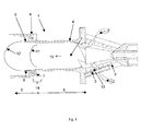
- FIG 1 which shows schematically a combustor 1 according to a preferred embodiment of the invention
- the combustor 1 may be for use in a sequentially operated gas turbine arrangement.
- a baffle 9 extends from the transition region 14 generally in the downstream direction 15 forming at least one space 10 between the combustor wall 4 and the baffle 9.
- the baffle extends preferably from the wall 4 of the combustor 1.
- the space 10 is only exposed to the main gas flow through the combustor at its downstream end. It has been found that providing a baffle 9 in this area has the effect of splitting the classical flame into two less intense flames denoted by the dotted lines 11 and 12.
- the first flame 11 develops from the area of the combustion front panel and the second flame develops from the area at the end of the baffle 9.
- the size of the first flame 11 is reduced compared to the single conventional flame 8 and the size of the flame 12 is larger than the size of the conventional flame 8.
- the high temperature area of these flames 11, 12 in this staged combustion is significantly reduced compared to the high temperature area of the single flame 8 in conventional combustors, therefore the production of NOx is also significantly reduced.
- Introducing the baffle 9 into the combustor in the position shown in figure 1 has been found to cool the hottest part of the flame and distribute the heat to the less hot parts of the flame thereby creating a more even temperature distribution throughout the flame, which is beneficial to reducing emissions.
- the turbine inlet temperature which is critical in determining the power of the turbine, remains the same.
- the baffle 9 is shown extending parallel with the centre axis of the combustor 1. It can however also extend at an angle to centerline of the combustor 1, or it may have a curved form.
- the baffle 9 extends preferably from the combustion front panel 7. The length of baffle 9 in the axial direction is chosen such that a secondary flame 12 can be created during combustion or such that sufficient cooling of the flame takes place.
- Cooling air or air from the combustion gases of a first combustor in a sequential combustion system is preferably introduced into the space between the combustor wall 4 and the baffle 9.
- the cooling air can be introduced through the combustor front panel 7 or it can be introduced through a passage in the baffle 9.
- the baffle can be effusion cooled whereby a plurality of small holes is provided in the baffle 9.
- the baffle 9 is cooled so that it has itself a cooling effect on the flame, which helps in reducing peak temperatures and NOx emissions.
- the invention can also be applied to an AEV (Advanced EnVironmental) combustor as shown schematically in figure 3 .
- AEV Advanced EnVironmental
- the oxidization air inlet 2 is formed by axial slots in the wall 4 of the combustor 1.
- the fuel is also injected through a plurality of holes in the wall 4 of the combustor 1.
Landscapes
- Engineering & Computer Science (AREA)
- Chemical & Material Sciences (AREA)
- Combustion & Propulsion (AREA)
- Mechanical Engineering (AREA)
- General Engineering & Computer Science (AREA)
Abstract
A baffle (9) extends from the transition region (14) generally in the downstream direction (15) forming at least one space (10) between the combustor wall (4) and the baffle (9).
Description
- The present invention relates to a combustor for a gas turbine, particularly for a gas turbine having sequential combustion.
- A gas turbine with sequential combustion is known to improve the efficiency of a gas turbine. This is achieved by increasing the turbine inlet temperature. In a sequential combustion gas turbine engine, fuel is burnt in a first combustor and the hot combustion gases are passed through a first turbine and subsequently supplied to a secondary combustor into which additional fuel is introduced. The combustion of the hot gases and the fuel is completed in the secondary combustor and the exhaust gases are subsequently supplied to the low pressure turbine. The secondary combustor has a mixing region where fuel is introduced and mixed with the combustion gases, and a downstream combustion region. The two regions are defined by a combustor wall having a combustion front panel positioned generally between the mixing and combustion regions.
- The secondary combustor is known in the art as an SEV (Sequential EnVironmental) combustor and the first combustor is known as EV (EnVironmental) or AEV (Advanced EnVironmental) combustor. Partly due to the introduction of hydrogen (H2) rich syngas fuels, which have higher flame speeds and temperatures there is a requirement to reduce emissions, particularly of NOx, which are produced under these conditions.
- The invention addresses a novel way to reduce NOx emissions. The present invention aims to provide a combustor for a gas turbine engine, particularly for a gas turbine having sequential combustion, with a reduced flame temperature thereby reducing levels of NOx emissions.
- According to the invention, these problems are solved by providing a combustor for a gas turbine engine with the features of
claim 1. Preferred embodiments of the combustor according to the invention can be found in the dependent claims. - According to the invention a combustor for a gas turbine engine, particularly for a gas turbine having sequential combustion, comprises a combustor wall defining a mixing region and a combustion region,The mixing region comprising at least one first inlet for introducing combustion air into the mixing region and at least one second inlet for introducing fuel into the mixing region,
- The combustion region extending downstream of the mixing region, and the mixing region crossing over to the combustion region in a transition region.
- A baffle extends from the transition region generally in the downstream direction forming at least one space between the combustor liner wall and the baffle.
- It has been found that providing a baffle in this area has the effect of splitting the classical SEV or EV flame into two less intense or low heat release flames. The peak temperatures of these flames in this staged combustion is significantly reduced compared to the peak temperatures encountered in a single flame as seen in conventional combustors, therefore the production of NOx is also significantly reduced. In addition to reduced emissions, the thermoacoustic oscillations due to heat release fluctuations are reduced due to distributed heat release.
- In a further preferred embodiment of the invention the baffle extends generally in the flow direction from a combustion front panel and the baffle is cooled by a cooling fluid or cooling air. The cooling provided to the baffle improves the cooling of the flame contributing to further reduction in NOx.
- In another embodiment, the amount of fuel and air flow rates through the mixing regions can be varied to obtain the desired flame characteristics.
- The above and other objects, features and advantages of the invention will become more apparent from the following description of certain preferred embodiments thereof, when taken in conjunction with the accompanying drawings.
- The invention is described referring to an embodiment depicted schematically in the drawings, and will be described with reference to the drawings in more details in the following.
-
- Figure 1
- a combustor according to one embodiment of the invention,
- Figure 2
- a prior art combustor for a sequential combustion gas turbine engine,
- Figure 3
- a combustor according to a second embodiment of the invention.
-
Fig. 2 shows schematically acombustor 1 for use in a sequentially operated gas turbine arrangement according to the state of the art. - The
combustor 1 shown infigure 2 is an SEV (Sequential EnVironmental) combustor. Afirst inlet 2 is provided at the upstream end of thecombustor 1 for introducing the hot gases from the first combustor (not shown) into theSEV combustor 1. These hot gases contain sufficient oxidizer for further combustion in theSEV combustor 1. Asecond inlet 3 arranged in a lance is provided downstream of the first inlet for introducing fuel into theSEV combustor 1. Thewall 4 of thecombustor 1 defines aregion 5 for mixing the fuel with the hot gases and acombustion region 6. The mixingregion 5 crosses over to thecombustion region 6 in atransition region 14. The cross sectional area of themixing region 5 is smaller than the cross sectional area of thecombustion region 6. Acombustor front panel 7 is arranged in a region between themixing region 5 and thecombustion region 6. The characteristics of combustion in such a combustor are largely determined by the amount of mixing of the fuel with the combustion gas in themixing region 5. Higher levels of fuel/air mixing induce thermo acoustic pulsations, where as lower levels of mixing results in formation of NOx. There are therefore conflicting aero/thermal goals, whereby it is difficult to achieve one without detriment to the other. Thedotted line 8 represents the general shape of the flame in theconventional combustor 1. It can be seen that the flame front develops in the region of thecombustor front panel 7 and extends a certain distance into thecombustion region 6. The area of the high temperature part of the flame is relatively large which leads to high levels of NOx production. - Now referring to
figure 1 , which shows schematically acombustor 1 according to a preferred embodiment of the invention, the same features as infigure 2 are designated with the same reference numerals. Thecombustor 1 may be for use in a sequentially operated gas turbine arrangement. According to the invention abaffle 9 extends from thetransition region 14 generally in thedownstream direction 15 forming at least onespace 10 between thecombustor wall 4 and thebaffle 9. The baffle extends preferably from thewall 4 of the combustor 1.Thespace 10 is only exposed to the main gas flow through the combustor at its downstream end. It has been found that providing abaffle 9 in this area has the effect of splitting the classical flame into two less intense flames denoted by thedotted lines first flame 11 develops from the area of the combustion front panel and the second flame develops from the area at the end of thebaffle 9. As can be seen from the figure the size of thefirst flame 11 is reduced compared to the singleconventional flame 8 and the size of theflame 12 is larger than the size of theconventional flame 8. The high temperature area of theseflames single flame 8 in conventional combustors, therefore the production of NOx is also significantly reduced. Introducing thebaffle 9 into the combustor in the position shown infigure 1 has been found to cool the hottest part of the flame and distribute the heat to the less hot parts of the flame thereby creating a more even temperature distribution throughout the flame, which is beneficial to reducing emissions. The turbine inlet temperature, which is critical in determining the power of the turbine, remains the same. - The
baffle 9 is shown extending parallel with the centre axis of thecombustor 1. It can however also extend at an angle to centerline of thecombustor 1, or it may have a curved form. Thebaffle 9 extends preferably from thecombustion front panel 7. The length ofbaffle 9 in the axial direction is chosen such that asecondary flame 12 can be created during combustion or such that sufficient cooling of the flame takes place. - Cooling air or air from the combustion gases of a first combustor in a sequential combustion system is preferably introduced into the space between the
combustor wall 4 and thebaffle 9. The cooling air can be introduced through the combustorfront panel 7 or it can be introduced through a passage in thebaffle 9. Alternatively the baffle can be effusion cooled whereby a plurality of small holes is provided in thebaffle 9. Thebaffle 9 is cooled so that it has itself a cooling effect on the flame, which helps in reducing peak temperatures and NOx emissions. - The invention can also be applied to an AEV (Advanced EnVironmental) combustor as shown schematically in
figure 3 . In an AEV combustor theoxidization air inlet 2 is formed by axial slots in thewall 4 of thecombustor 1. The fuel is also injected through a plurality of holes in thewall 4 of thecombustor 1. - Due to the introduction of the
baffles 9 the emissions of NOx can be reduced. Therefore less stringent procedures can be adopted for controlling the fuel air mixing in the mixingregion 5. - The preceding description of the embodiments according to the present invention serves only an illustrative purpose and should not be considered to limit the scope of the invention.
- Particularly, in view of the preferred embodiments, the man skilled in the art different changes and modifications in the form and details can be made without departing from the scope of the invention. Accordingly the disclosure of the current invention should not be limiting. The disclosure of the current invention should instead serve to clarify the scope of the invention which is set forth in the following claims.
-
- 1.
- Combustor
- 2.
- First inlet
- 3.
- Second inlet
- 4.
- Combustor wall
- 5.
- Mixing region
- 6.
- Combustion region
- 7.
- Combustion front panel
- 8.
- Dotted line
- 9.
- Baffle
- 10.
- Space
- 11.
- First flame
- 12.
- Second flame
- 13.
- Slot(s)
- 14.
- Transition region
- 15.
- Flowdirection
Claims (10)
- A combustor (1) for a gas turbine engine, particularly for a gas turbine having sequential combustion, comprising, a combustor wall (4) defining a mixing region (5) and a combustion region (6),the mixing region (5) comprising at least one first inlet (2) for introducing combustion air into the mixing region (5) and at least one second inlet (3) for introducing fuel into the mixing region (5), the combustion region (6) extending downstream of the mixing region, the mixing region (5) crossing over to the combustion region (6) in a transition region (14),
characterized in that a baffle (9) extends from the transition region (14) generally in the downstream direction (15) forming at least one space (10) between the combustor wall (4) and the baffle (9). - The combustor according to claim 1 characterized in that the cross sectional area of the combustor (1) increases between the mixing region (5) and the combustion region (6).
- The combustor according to claim 2 characterized in that the baffle (9) extends generally in the flow direction from a combustion front panel (7).
- The combustor according to any one of the preceding claims, characterized in that a cooling fluid or cooling air is introduced into the space (10) between the combustor wall (4) and the baffle (9).
- The combustor according to any one of the preceding claims, characterized in that cooling air or exhaust gas is introduced into the baffle (9).
- The combustor according to any one of the preceding claims, characterized in that the baffle (9) is provided with holes for effusion cooling of the baffle with air or combustion gas.
- The combustor according to any one of the preceding claims, characterized in that the length of baffle (9) in the axial direction is such that a secondary flame (12) can be created during combustion.
- The combustor according to claim 1 characterized in that the combustor (1) is an SEV combustor, characterized in that the at least one second inlet (3) for introducing fuel into the combustor (1) is provided on a fuel lance which projects into the combustor (1).
- The combustor according to claim 1 characterized in that the combustor (1) is an AEV combustor whereby the combustion air and fuel are introduced into the mixing region through slots or holes in the walls of the combustor.
- A sequentially operated gas turbine arrangement having a combustor according to one of the preceding claims.
Applications Claiming Priority (1)
| Application Number | Priority Date | Filing Date | Title |
|---|---|---|---|
| US12/241,199 US8220269B2 (en) | 2008-09-30 | 2008-09-30 | Combustor for a gas turbine engine with effusion cooled baffle |
Publications (3)
| Publication Number | Publication Date |
|---|---|
| EP2169303A2 true EP2169303A2 (en) | 2010-03-31 |
| EP2169303A3 EP2169303A3 (en) | 2014-12-24 |
| EP2169303B1 EP2169303B1 (en) | 2017-04-26 |
Family
ID=41445525
Family Applications (1)
| Application Number | Title | Priority Date | Filing Date |
|---|---|---|---|
| EP09170923.8A Not-in-force EP2169303B1 (en) | 2008-09-30 | 2009-09-22 | Combustor for a gas turbine engine |
Country Status (3)
| Country | Link |
|---|---|
| US (1) | US8220269B2 (en) |
| EP (1) | EP2169303B1 (en) |
| JP (1) | JP5574658B2 (en) |
Cited By (2)
| Publication number | Priority date | Publication date | Assignee | Title |
|---|---|---|---|---|
| US11156164B2 (en) | 2019-05-21 | 2021-10-26 | General Electric Company | System and method for high frequency accoustic dampers with caps |
| US11174792B2 (en) | 2019-05-21 | 2021-11-16 | General Electric Company | System and method for high frequency acoustic dampers with baffles |
Families Citing this family (12)
| Publication number | Priority date | Publication date | Assignee | Title |
|---|---|---|---|---|
| EP2085695A1 (en) * | 2008-01-29 | 2009-08-05 | Siemens Aktiengesellschaft | Fuel nozzle with swirl duct and method for manufacturing a fuel nozzle |
| US8220271B2 (en) * | 2008-09-30 | 2012-07-17 | Alstom Technology Ltd. | Fuel lance for a gas turbine engine including outer helical grooves |
| US8511059B2 (en) * | 2008-09-30 | 2013-08-20 | Alstom Technology Ltd. | Methods of reducing emissions for a sequential combustion gas turbine and combustor for a gas turbine |
| US11143407B2 (en) | 2013-06-11 | 2021-10-12 | Raytheon Technologies Corporation | Combustor with axial staging for a gas turbine engine |
| WO2015147932A2 (en) | 2013-12-19 | 2015-10-01 | United Technologies Corporation | Dilution passage arrangement for gas turbine engine combustor |
| WO2016024975A1 (en) | 2014-08-14 | 2016-02-18 | Siemens Aktiengesellschaft | Multi-functional fuel nozzle with a heat shield |
| US9958152B2 (en) | 2014-08-14 | 2018-05-01 | Siemens Aktiengesellschaft | Multi-functional fuel nozzle with an atomizer array |
| JP6410924B2 (en) | 2014-08-14 | 2018-10-24 | シーメンス アクチエンゲゼルシヤフトSiemens Aktiengesellschaft | Multifunctional fuel nozzle with dual orifice atomizer |
| EP3026346A1 (en) * | 2014-11-25 | 2016-06-01 | Alstom Technology Ltd | Combustor liner |
| MX2018015558A (en) | 2016-07-08 | 2019-06-06 | Nova Chem Int Sa | Metallic burner tiles. |
| US10739003B2 (en) | 2016-10-03 | 2020-08-11 | United Technologies Corporation | Radial fuel shifting and biasing in an axial staged combustor for a gas turbine engine |
| US10508811B2 (en) | 2016-10-03 | 2019-12-17 | United Technologies Corporation | Circumferential fuel shifting and biasing in an axial staged combustor for a gas turbine engine |
Family Cites Families (72)
| Publication number | Priority date | Publication date | Assignee | Title |
|---|---|---|---|---|
| US1866311A (en) * | 1931-03-26 | 1932-07-05 | Leiman Bros Inc | Hydrocarbon burner |
| US2701164A (en) * | 1951-04-26 | 1955-02-01 | Gen Motors Corp | Duplex fuel nozzle |
| US3510064A (en) * | 1966-10-26 | 1970-05-05 | British Oxygen Co Ltd | Oxy-fuel flame burner nozzles |
| US3648457A (en) * | 1970-04-30 | 1972-03-14 | Gen Electric | Combustion apparatus |
| GB1553875A (en) * | 1975-08-27 | 1979-10-10 | Exxon France | Atomizer and method of burning |
| US4258544A (en) * | 1978-09-15 | 1981-03-31 | Caterpillar Tractor Co. | Dual fluid fuel nozzle |
| US4457241A (en) * | 1981-12-23 | 1984-07-03 | Riley Stoker Corporation | Method of burning pulverized coal |
| JPS6057131A (en) * | 1983-09-08 | 1985-04-02 | Hitachi Ltd | Fuel feeding process for gas turbine combustor |
| US4982570A (en) * | 1986-11-25 | 1991-01-08 | General Electric Company | Premixed pilot nozzle for dry low Nox combustor |
| US4952136A (en) * | 1987-05-12 | 1990-08-28 | Control Systems Company | Burner assembly for oil fired furnaces |
| JPH0684817B2 (en) * | 1988-08-08 | 1994-10-26 | 株式会社日立製作所 | Gas turbine combustor and operating method thereof |
| JP2713627B2 (en) * | 1989-03-20 | 1998-02-16 | 株式会社日立製作所 | Gas turbine combustor, gas turbine equipment including the same, and combustion method |
| JPH0772616B2 (en) * | 1989-05-24 | 1995-08-02 | 株式会社日立製作所 | Combustor and operating method thereof |
| US5749219A (en) * | 1989-11-30 | 1998-05-12 | United Technologies Corporation | Combustor with first and second zones |
| US5129333A (en) * | 1991-06-24 | 1992-07-14 | Aga Ab | Apparatus and method for recycling waste |
| US5406799A (en) * | 1992-06-12 | 1995-04-18 | United Technologies Corporation | Combustion chamber |
| US5405082A (en) * | 1993-07-06 | 1995-04-11 | Corning Incorporated | Oxy/fuel burner with low volume fuel stream projection |
| US5393220A (en) * | 1993-12-06 | 1995-02-28 | Praxair Technology, Inc. | Combustion apparatus and process |
| US5465570A (en) * | 1993-12-22 | 1995-11-14 | United Technologies Corporation | Fuel control system for a staged combustor |
| CA2141066A1 (en) * | 1994-02-18 | 1995-08-19 | Urs Benz | Process for the cooling of an auto-ignition combustion chamber |
| CH688899A5 (en) * | 1994-05-26 | 1998-05-15 | Asea Brown Boveri | A method for controlling a gas turbine group. |
| US5701732A (en) * | 1995-01-24 | 1997-12-30 | Delavan Inc. | Method and apparatus for purging of gas turbine injectors |
| US5836164A (en) * | 1995-01-30 | 1998-11-17 | Hitachi, Ltd. | Gas turbine combustor |
| US5687571A (en) * | 1995-02-20 | 1997-11-18 | Asea Brown Boveri Ag | Combustion chamber with two-stage combustion |
| US6076356A (en) * | 1996-03-13 | 2000-06-20 | Parker-Hannifin Corporation | Internally heatshielded nozzle |
| DE19737997A1 (en) * | 1997-08-30 | 1999-03-04 | Asea Brown Boveri | plenum |
| EP0911583B1 (en) * | 1997-10-27 | 2003-03-12 | ALSTOM (Switzerland) Ltd | Method of operating a premix burner |
| EP0916894B1 (en) * | 1997-11-13 | 2003-09-24 | ALSTOM (Switzerland) Ltd | Burner for operating a heat generator |
| EP0921292B1 (en) * | 1997-12-08 | 2003-09-10 | ALSTOM (Switzerland) Ltd | Method for controlling a gas turbine group |
| US6029910A (en) * | 1998-02-05 | 2000-02-29 | American Air Liquide, Inc. | Low firing rate oxy-fuel burner |
| US6098407A (en) * | 1998-06-08 | 2000-08-08 | United Technologies Corporation | Premixing fuel injector with improved secondary fuel-air injection |
| US6339923B1 (en) * | 1998-10-09 | 2002-01-22 | General Electric Company | Fuel air mixer for a radial dome in a gas turbine engine combustor |
| US6089024A (en) * | 1998-11-25 | 2000-07-18 | Elson Corporation | Steam-augmented gas turbine |
| US6460344B1 (en) * | 1999-05-07 | 2002-10-08 | Parker-Hannifin Corporation | Fuel atomization method for turbine combustion engines having aerodynamic turning vanes |
| US6174161B1 (en) * | 1999-07-30 | 2001-01-16 | Air Products And Chemical, Inc. | Method and apparatus for partial oxidation of black liquor, liquid fuels and slurries |
| US6871503B1 (en) * | 1999-10-20 | 2005-03-29 | Hitachi, Ltd. | Gas turbine combustor with fuel-air pre-mixer and pre-mixing method for low nox combustion |
| US6089468A (en) * | 1999-11-08 | 2000-07-18 | Husky Injection Molding Systems Ltd. | Nozzle tip with weld line eliminator |
| US6351947B1 (en) * | 2000-04-04 | 2002-03-05 | Abb Alstom Power (Schweiz) | Combustion chamber for a gas turbine |
| DE10061526A1 (en) * | 2000-12-11 | 2002-06-20 | Alstom Switzerland Ltd | Premix burner arrangement for operating a combustion chamber |
| US6622488B2 (en) * | 2001-03-21 | 2003-09-23 | Parker-Hannifin Corporation | Pure airblast nozzle |
| US6539724B2 (en) * | 2001-03-30 | 2003-04-01 | Delavan Inc | Airblast fuel atomization system |
| DE10128063A1 (en) * | 2001-06-09 | 2003-01-23 | Alstom Switzerland Ltd | burner system |
| US6581386B2 (en) * | 2001-09-29 | 2003-06-24 | General Electric Company | Threaded combustor baffle |
| DE50206249D1 (en) * | 2001-10-30 | 2006-05-18 | Alstom Technology Ltd | TURBOMACHINE |
| US6832482B2 (en) * | 2002-06-25 | 2004-12-21 | Power Systems Mfg, Llc | Pressure ram device on a gas turbine combustor |
| GB2390150A (en) * | 2002-06-26 | 2003-12-31 | Alstom | Reheat combustion system for a gas turbine including an accoustic screen |
| EP1389713A1 (en) * | 2002-08-12 | 2004-02-18 | ALSTOM (Switzerland) Ltd | Premixed exit ring pilot burner |
| FR2856468B1 (en) * | 2003-06-17 | 2007-11-23 | Snecma Moteurs | TURBOMACHINE ANNULAR COMBUSTION CHAMBER |
| JP3940705B2 (en) * | 2003-06-19 | 2007-07-04 | 株式会社日立製作所 | Gas turbine combustor and fuel supply method thereof |
| DE10360951A1 (en) * | 2003-12-23 | 2005-07-28 | Alstom Technology Ltd | Thermal power plant with sequential combustion and reduced CO2 emissions and method of operating such a plant |
| US7082770B2 (en) * | 2003-12-24 | 2006-08-01 | Martling Vincent C | Flow sleeve for a low NOx combustor |
| US7174717B2 (en) * | 2003-12-24 | 2007-02-13 | Pratt & Whitney Canada Corp. | Helical channel fuel distributor and method |
| US7185497B2 (en) * | 2004-05-04 | 2007-03-06 | Honeywell International, Inc. | Rich quick mix combustion system |
| US7788897B2 (en) * | 2004-06-11 | 2010-09-07 | Vast Power Portfolio, Llc | Low emissions combustion apparatus and method |
| US7883026B2 (en) * | 2004-06-30 | 2011-02-08 | Illinois Tool Works Inc. | Fluid atomizing system and method |
| FR2875584B1 (en) * | 2004-09-23 | 2009-10-30 | Snecma Moteurs Sa | EFFERVESCENCE INJECTOR FOR AEROMECHANICAL AIR / FUEL INJECTION SYSTEM IN A TURBOMACHINE COMBUSTION CHAMBER |
| US7416404B2 (en) * | 2005-04-18 | 2008-08-26 | General Electric Company | Feed injector for gasification and related method |
| DE102005042889B4 (en) * | 2005-09-09 | 2019-05-09 | Ansaldo Energia Switzerland AG | Gas turbine group |
| US20070107437A1 (en) * | 2005-11-15 | 2007-05-17 | Evulet Andrei T | Low emission combustion and method of operation |
| EP1840354B1 (en) * | 2006-03-28 | 2017-11-29 | Ansaldo Energia IP UK Limited | Method for operating a gas turbine plant and gas turbine plant for carrying out the method |
| EP2002185B8 (en) * | 2006-03-31 | 2016-09-14 | General Electric Technology GmbH | Fuel lance for a gas turbine plant and a method of operating a fuel lance |
| US7762070B2 (en) * | 2006-05-11 | 2010-07-27 | Siemens Energy, Inc. | Pilot nozzle heat shield having internal turbulators |
| JP5021730B2 (en) * | 2006-06-07 | 2012-09-12 | アルストム テクノロジー リミテッド | Method for operation of a gas turbine and combined cycle power plant for the implementation of the method |
| EP1914407B1 (en) * | 2006-10-16 | 2012-01-04 | Alstom Technology Ltd | Method for operating a gas turbine plant |
| US8015815B2 (en) * | 2007-04-18 | 2011-09-13 | Parker-Hannifin Corporation | Fuel injector nozzles, with labyrinth grooves, for gas turbine engines |
| US8020384B2 (en) * | 2007-06-14 | 2011-09-20 | Parker-Hannifin Corporation | Fuel injector nozzle with macrolaminate fuel swirler |
| EP2090830B1 (en) * | 2008-02-13 | 2017-01-18 | General Electric Technology GmbH | Fuel supply arrangement |
| US8281595B2 (en) * | 2008-05-28 | 2012-10-09 | General Electric Company | Fuse for flame holding abatement in premixer of combustion chamber of gas turbine and associated method |
| US8272218B2 (en) * | 2008-09-24 | 2012-09-25 | Siemens Energy, Inc. | Spiral cooled fuel nozzle |
| US8220271B2 (en) * | 2008-09-30 | 2012-07-17 | Alstom Technology Ltd. | Fuel lance for a gas turbine engine including outer helical grooves |
| US8511059B2 (en) * | 2008-09-30 | 2013-08-20 | Alstom Technology Ltd. | Methods of reducing emissions for a sequential combustion gas turbine and combustor for a gas turbine |
| US20100205970A1 (en) * | 2009-02-19 | 2010-08-19 | General Electric Company | Systems, Methods, and Apparatus Providing a Secondary Fuel Nozzle Assembly |
-
2008
- 2008-09-30 US US12/241,199 patent/US8220269B2/en active Active
-
2009
- 2009-09-22 EP EP09170923.8A patent/EP2169303B1/en not_active Not-in-force
- 2009-09-29 JP JP2009224155A patent/JP5574658B2/en not_active Expired - Fee Related
Cited By (2)
| Publication number | Priority date | Publication date | Assignee | Title |
|---|---|---|---|---|
| US11156164B2 (en) | 2019-05-21 | 2021-10-26 | General Electric Company | System and method for high frequency accoustic dampers with caps |
| US11174792B2 (en) | 2019-05-21 | 2021-11-16 | General Electric Company | System and method for high frequency acoustic dampers with baffles |
Also Published As
| Publication number | Publication date |
|---|---|
| US20100077757A1 (en) | 2010-04-01 |
| JP5574658B2 (en) | 2014-08-20 |
| JP2010085085A (en) | 2010-04-15 |
| EP2169303B1 (en) | 2017-04-26 |
| EP2169303A3 (en) | 2014-12-24 |
| US8220269B2 (en) | 2012-07-17 |
Similar Documents
| Publication | Publication Date | Title |
|---|---|---|
| EP2169303B1 (en) | Combustor for a gas turbine engine | |
| EP2169313B1 (en) | Fuel Lance for a Gas Turbine Engine | |
| CN103307636B (en) | System for working fluid to be fed to burner | |
| JP4087372B2 (en) | Gas turbine engine combustor and its design method | |
| JP6231114B2 (en) | Two-stage combustion with dilution gas mixer | |
| US7448218B2 (en) | Premix burner and method for burning a low-calorie combustion gas | |
| CN104061595B (en) | Continuous burning bushing for the burner of combustion gas turbine | |
| CN102192508B (en) | The premixed combustor of classification vertically | |
| EP2889542B1 (en) | Method for operating a combustor for a gas turbine and combustor for a gas turbine | |
| CN101294715A (en) | Combustion device and combustion method of burner | |
| JP5875647B2 (en) | Two-stage combustion with dilution gas mixer | |
| WO2008097320A2 (en) | Premixing injector for gas turbine engines | |
| JP2010243146A (en) | Premixed direct injection injector | |
| JP2010091258A (en) | Premixed direct injection nozzle | |
| JP2008122065A (en) | High expansion fuel injection slot jet and method for enhancing mixing in a premixer | |
| JPH04251118A (en) | Combustion assembly having dilution-stage | |
| JP2016017740A (en) | Two-stage combustor arrangement with mixer | |
| JP2016156608A (en) | Two-stage combustor arrangement with mixer | |
| JP2015132462A (en) | Sequential combustion arrangement with dilution gas | |
| JP2010216481A (en) | Gas turbine burner and method for partially cooling hot gas flow passing through burner | |
| EP2420731B1 (en) | Reheat burner | |
| CN113776082A (en) | An air-cooled wall type support plate combined flame stabilizer and combustion chamber | |
| WO2007104599A1 (en) | Burner, in particular for a gas turbine combustor, and method of operating a burner | |
| JP2004534199A (en) | Cyclone combustor | |
| RU2379537C2 (en) | Method to improve ignition in two-flow turbojet engine afterburner and afterburner to this end |
Legal Events
| Date | Code | Title | Description |
|---|---|---|---|
| PUAI | Public reference made under article 153(3) epc to a published international application that has entered the european phase |
Free format text: ORIGINAL CODE: 0009012 |
|
| AK | Designated contracting states |
Kind code of ref document: A2 Designated state(s): AT BE BG CH CY CZ DE DK EE ES FI FR GB GR HR HU IE IS IT LI LT LU LV MC MK MT NL NO PL PT RO SE SI SK SM TR |
|
| PUAL | Search report despatched |
Free format text: ORIGINAL CODE: 0009013 |
|
| AK | Designated contracting states |
Kind code of ref document: A3 Designated state(s): AT BE BG CH CY CZ DE DK EE ES FI FR GB GR HR HU IE IS IT LI LT LU LV MC MK MT NL NO PL PT RO SE SI SK SM TR |
|
| RIC1 | Information provided on ipc code assigned before grant |
Ipc: F23C 6/04 20060101AFI20141117BHEP Ipc: F23R 3/34 20060101ALI20141117BHEP Ipc: F23R 3/00 20060101ALI20141117BHEP Ipc: F23M 9/10 20060101ALI20141117BHEP |
|
| 17P | Request for examination filed |
Effective date: 20150624 |
|
| RBV | Designated contracting states (corrected) |
Designated state(s): AT BE BG CH CY CZ DE DK EE ES FI FR GB GR HR HU IE IS IT LI LT LU LV MC MK MT NL NO PL PT RO SE SI SK SM TR |
|
| 17Q | First examination report despatched |
Effective date: 20151112 |
|
| RAP1 | Party data changed (applicant data changed or rights of an application transferred) |
Owner name: GENERAL ELECTRIC TECHNOLOGY GMBH |
|
| GRAP | Despatch of communication of intention to grant a patent |
Free format text: ORIGINAL CODE: EPIDOSNIGR1 |
|
| INTG | Intention to grant announced |
Effective date: 20161125 |
|
| GRAS | Grant fee paid |
Free format text: ORIGINAL CODE: EPIDOSNIGR3 |
|
| GRAA | (expected) grant |
Free format text: ORIGINAL CODE: 0009210 |
|
| AK | Designated contracting states |
Kind code of ref document: B1 Designated state(s): AT BE BG CH CY CZ DE DK EE ES FI FR GB GR HR HU IE IS IT LI LT LU LV MC MK MT NL NO PL PT RO SE SI SK SM TR |
|
| REG | Reference to a national code |
Ref country code: GB Ref legal event code: FG4D |
|
| REG | Reference to a national code |
Ref country code: CH Ref legal event code: EP |
|
| REG | Reference to a national code |
Ref country code: AT Ref legal event code: REF Ref document number: 888212 Country of ref document: AT Kind code of ref document: T Effective date: 20170515 |
|
| REG | Reference to a national code |
Ref country code: IE Ref legal event code: FG4D |
|
| RAP2 | Party data changed (patent owner data changed or rights of a patent transferred) |
Owner name: ANSALDO ENERGIA SWITZERLAND AG |
|
| REG | Reference to a national code |
Ref country code: DE Ref legal event code: R096 Ref document number: 602009045662 Country of ref document: DE |
|
| REG | Reference to a national code |
Ref country code: NL Ref legal event code: MP Effective date: 20170426 |
|
| REG | Reference to a national code |
Ref country code: LT Ref legal event code: MG4D |
|
| REG | Reference to a national code |
Ref country code: AT Ref legal event code: MK05 Ref document number: 888212 Country of ref document: AT Kind code of ref document: T Effective date: 20170426 |
|
| PG25 | Lapsed in a contracting state [announced via postgrant information from national office to epo] |
Ref country code: NL Free format text: LAPSE BECAUSE OF FAILURE TO SUBMIT A TRANSLATION OF THE DESCRIPTION OR TO PAY THE FEE WITHIN THE PRESCRIBED TIME-LIMIT Effective date: 20170426 |
|
| PG25 | Lapsed in a contracting state [announced via postgrant information from national office to epo] |
Ref country code: LT Free format text: LAPSE BECAUSE OF FAILURE TO SUBMIT A TRANSLATION OF THE DESCRIPTION OR TO PAY THE FEE WITHIN THE PRESCRIBED TIME-LIMIT Effective date: 20170426 Ref country code: AT Free format text: LAPSE BECAUSE OF FAILURE TO SUBMIT A TRANSLATION OF THE DESCRIPTION OR TO PAY THE FEE WITHIN THE PRESCRIBED TIME-LIMIT Effective date: 20170426 Ref country code: NO Free format text: LAPSE BECAUSE OF FAILURE TO SUBMIT A TRANSLATION OF THE DESCRIPTION OR TO PAY THE FEE WITHIN THE PRESCRIBED TIME-LIMIT Effective date: 20170726 Ref country code: ES Free format text: LAPSE BECAUSE OF FAILURE TO SUBMIT A TRANSLATION OF THE DESCRIPTION OR TO PAY THE FEE WITHIN THE PRESCRIBED TIME-LIMIT Effective date: 20170426 Ref country code: GR Free format text: LAPSE BECAUSE OF FAILURE TO SUBMIT A TRANSLATION OF THE DESCRIPTION OR TO PAY THE FEE WITHIN THE PRESCRIBED TIME-LIMIT Effective date: 20170727 Ref country code: FI Free format text: LAPSE BECAUSE OF FAILURE TO SUBMIT A TRANSLATION OF THE DESCRIPTION OR TO PAY THE FEE WITHIN THE PRESCRIBED TIME-LIMIT Effective date: 20170426 Ref country code: HR Free format text: LAPSE BECAUSE OF FAILURE TO SUBMIT A TRANSLATION OF THE DESCRIPTION OR TO PAY THE FEE WITHIN THE PRESCRIBED TIME-LIMIT Effective date: 20170426 |
|
| PG25 | Lapsed in a contracting state [announced via postgrant information from national office to epo] |
Ref country code: PL Free format text: LAPSE BECAUSE OF FAILURE TO SUBMIT A TRANSLATION OF THE DESCRIPTION OR TO PAY THE FEE WITHIN THE PRESCRIBED TIME-LIMIT Effective date: 20170426 Ref country code: SE Free format text: LAPSE BECAUSE OF FAILURE TO SUBMIT A TRANSLATION OF THE DESCRIPTION OR TO PAY THE FEE WITHIN THE PRESCRIBED TIME-LIMIT Effective date: 20170426 Ref country code: BG Free format text: LAPSE BECAUSE OF FAILURE TO SUBMIT A TRANSLATION OF THE DESCRIPTION OR TO PAY THE FEE WITHIN THE PRESCRIBED TIME-LIMIT Effective date: 20170726 Ref country code: IS Free format text: LAPSE BECAUSE OF FAILURE TO SUBMIT A TRANSLATION OF THE DESCRIPTION OR TO PAY THE FEE WITHIN THE PRESCRIBED TIME-LIMIT Effective date: 20170826 Ref country code: LV Free format text: LAPSE BECAUSE OF FAILURE TO SUBMIT A TRANSLATION OF THE DESCRIPTION OR TO PAY THE FEE WITHIN THE PRESCRIBED TIME-LIMIT Effective date: 20170426 |
|
| REG | Reference to a national code |
Ref country code: DE Ref legal event code: R097 Ref document number: 602009045662 Country of ref document: DE |
|
| PG25 | Lapsed in a contracting state [announced via postgrant information from national office to epo] |
Ref country code: EE Free format text: LAPSE BECAUSE OF FAILURE TO SUBMIT A TRANSLATION OF THE DESCRIPTION OR TO PAY THE FEE WITHIN THE PRESCRIBED TIME-LIMIT Effective date: 20170426 Ref country code: RO Free format text: LAPSE BECAUSE OF FAILURE TO SUBMIT A TRANSLATION OF THE DESCRIPTION OR TO PAY THE FEE WITHIN THE PRESCRIBED TIME-LIMIT Effective date: 20170426 Ref country code: DK Free format text: LAPSE BECAUSE OF FAILURE TO SUBMIT A TRANSLATION OF THE DESCRIPTION OR TO PAY THE FEE WITHIN THE PRESCRIBED TIME-LIMIT Effective date: 20170426 Ref country code: SK Free format text: LAPSE BECAUSE OF FAILURE TO SUBMIT A TRANSLATION OF THE DESCRIPTION OR TO PAY THE FEE WITHIN THE PRESCRIBED TIME-LIMIT Effective date: 20170426 Ref country code: CZ Free format text: LAPSE BECAUSE OF FAILURE TO SUBMIT A TRANSLATION OF THE DESCRIPTION OR TO PAY THE FEE WITHIN THE PRESCRIBED TIME-LIMIT Effective date: 20170426 |
|
| PG25 | Lapsed in a contracting state [announced via postgrant information from national office to epo] |
Ref country code: SM Free format text: LAPSE BECAUSE OF FAILURE TO SUBMIT A TRANSLATION OF THE DESCRIPTION OR TO PAY THE FEE WITHIN THE PRESCRIBED TIME-LIMIT Effective date: 20170426 |
|
| PLBE | No opposition filed within time limit |
Free format text: ORIGINAL CODE: 0009261 |
|
| STAA | Information on the status of an ep patent application or granted ep patent |
Free format text: STATUS: NO OPPOSITION FILED WITHIN TIME LIMIT |
|
| 26N | No opposition filed |
Effective date: 20180129 |
|
| REG | Reference to a national code |
Ref country code: CH Ref legal event code: PL |
|
| PG25 | Lapsed in a contracting state [announced via postgrant information from national office to epo] |
Ref country code: MC Free format text: LAPSE BECAUSE OF FAILURE TO SUBMIT A TRANSLATION OF THE DESCRIPTION OR TO PAY THE FEE WITHIN THE PRESCRIBED TIME-LIMIT Effective date: 20170426 Ref country code: SI Free format text: LAPSE BECAUSE OF FAILURE TO SUBMIT A TRANSLATION OF THE DESCRIPTION OR TO PAY THE FEE WITHIN THE PRESCRIBED TIME-LIMIT Effective date: 20170426 |
|
| REG | Reference to a national code |
Ref country code: IE Ref legal event code: MM4A |
|
| REG | Reference to a national code |
Ref country code: BE Ref legal event code: MM Effective date: 20170930 |
|
| PG25 | Lapsed in a contracting state [announced via postgrant information from national office to epo] |
Ref country code: LU Free format text: LAPSE BECAUSE OF NON-PAYMENT OF DUE FEES Effective date: 20170922 |
|
| REG | Reference to a national code |
Ref country code: FR Ref legal event code: ST Effective date: 20180531 |
|
| PG25 | Lapsed in a contracting state [announced via postgrant information from national office to epo] |
Ref country code: IE Free format text: LAPSE BECAUSE OF NON-PAYMENT OF DUE FEES Effective date: 20170922 Ref country code: CH Free format text: LAPSE BECAUSE OF NON-PAYMENT OF DUE FEES Effective date: 20170930 Ref country code: LI Free format text: LAPSE BECAUSE OF NON-PAYMENT OF DUE FEES Effective date: 20170930 |
|
| PG25 | Lapsed in a contracting state [announced via postgrant information from national office to epo] |
Ref country code: BE Free format text: LAPSE BECAUSE OF NON-PAYMENT OF DUE FEES Effective date: 20170930 Ref country code: FR Free format text: LAPSE BECAUSE OF NON-PAYMENT OF DUE FEES Effective date: 20171002 |
|
| PG25 | Lapsed in a contracting state [announced via postgrant information from national office to epo] |
Ref country code: MT Free format text: LAPSE BECAUSE OF NON-PAYMENT OF DUE FEES Effective date: 20170922 |
|
| PG25 | Lapsed in a contracting state [announced via postgrant information from national office to epo] |
Ref country code: HU Free format text: LAPSE BECAUSE OF FAILURE TO SUBMIT A TRANSLATION OF THE DESCRIPTION OR TO PAY THE FEE WITHIN THE PRESCRIBED TIME-LIMIT; INVALID AB INITIO Effective date: 20090922 |
|
| PG25 | Lapsed in a contracting state [announced via postgrant information from national office to epo] |
Ref country code: CY Free format text: LAPSE BECAUSE OF NON-PAYMENT OF DUE FEES Effective date: 20170426 |
|
| PG25 | Lapsed in a contracting state [announced via postgrant information from national office to epo] |
Ref country code: MK Free format text: LAPSE BECAUSE OF FAILURE TO SUBMIT A TRANSLATION OF THE DESCRIPTION OR TO PAY THE FEE WITHIN THE PRESCRIBED TIME-LIMIT Effective date: 20170426 |
|
| PG25 | Lapsed in a contracting state [announced via postgrant information from national office to epo] |
Ref country code: TR Free format text: LAPSE BECAUSE OF FAILURE TO SUBMIT A TRANSLATION OF THE DESCRIPTION OR TO PAY THE FEE WITHIN THE PRESCRIBED TIME-LIMIT Effective date: 20170426 |
|
| PG25 | Lapsed in a contracting state [announced via postgrant information from national office to epo] |
Ref country code: PT Free format text: LAPSE BECAUSE OF FAILURE TO SUBMIT A TRANSLATION OF THE DESCRIPTION OR TO PAY THE FEE WITHIN THE PRESCRIBED TIME-LIMIT Effective date: 20170426 |
|
| PGFP | Annual fee paid to national office [announced via postgrant information from national office to epo] |
Ref country code: DE Payment date: 20240130 Year of fee payment: 15 Ref country code: GB Payment date: 20240130 Year of fee payment: 15 |
|
| PGFP | Annual fee paid to national office [announced via postgrant information from national office to epo] |
Ref country code: IT Payment date: 20240130 Year of fee payment: 15 |
|
| P01 | Opt-out of the competence of the unified patent court (upc) registered |
Effective date: 20240430 |
|
| REG | Reference to a national code |
Ref country code: DE Ref legal event code: R119 Ref document number: 602009045662 Country of ref document: DE |
|
| GBPC | Gb: european patent ceased through non-payment of renewal fee |
Effective date: 20240922 |
|
| PG25 | Lapsed in a contracting state [announced via postgrant information from national office to epo] |
Ref country code: DE Free format text: LAPSE BECAUSE OF NON-PAYMENT OF DUE FEES Effective date: 20250401 |
|
| PG25 | Lapsed in a contracting state [announced via postgrant information from national office to epo] |
Ref country code: GB Free format text: LAPSE BECAUSE OF NON-PAYMENT OF DUE FEES Effective date: 20240922 |
|
| PG25 | Lapsed in a contracting state [announced via postgrant information from national office to epo] |
Ref country code: IT Free format text: LAPSE BECAUSE OF NON-PAYMENT OF DUE FEES Effective date: 20240922 |