EP2169281A1 - Wire rod for i-type oil ring, and its manufacturing method - Google Patents
Wire rod for i-type oil ring, and its manufacturing method Download PDFInfo
- Publication number
- EP2169281A1 EP2169281A1 EP08765428A EP08765428A EP2169281A1 EP 2169281 A1 EP2169281 A1 EP 2169281A1 EP 08765428 A EP08765428 A EP 08765428A EP 08765428 A EP08765428 A EP 08765428A EP 2169281 A1 EP2169281 A1 EP 2169281A1
- Authority
- EP
- European Patent Office
- Prior art keywords
- wire
- hole
- remelted
- holes
- solidified portion
- Prior art date
- Legal status (The legal status is an assumption and is not a legal conclusion. Google has not performed a legal analysis and makes no representation as to the accuracy of the status listed.)
- Granted
Links
Images


Classifications
-
- B—PERFORMING OPERATIONS; TRANSPORTING
- B23—MACHINE TOOLS; METAL-WORKING NOT OTHERWISE PROVIDED FOR
- B23K—SOLDERING OR UNSOLDERING; WELDING; CLADDING OR PLATING BY SOLDERING OR WELDING; CUTTING BY APPLYING HEAT LOCALLY, e.g. FLAME CUTTING; WORKING BY LASER BEAM
- B23K26/00—Working by laser beam, e.g. welding, cutting or boring
- B23K26/36—Removing material
- B23K26/38—Removing material by boring or cutting
- B23K26/382—Removing material by boring or cutting by boring
- B23K26/384—Removing material by boring or cutting by boring of specially shaped holes
-
- F—MECHANICAL ENGINEERING; LIGHTING; HEATING; WEAPONS; BLASTING
- F16—ENGINEERING ELEMENTS AND UNITS; GENERAL MEASURES FOR PRODUCING AND MAINTAINING EFFECTIVE FUNCTIONING OF MACHINES OR INSTALLATIONS; THERMAL INSULATION IN GENERAL
- F16J—PISTONS; CYLINDERS; SEALINGS
- F16J9/00—Piston-rings, e.g. non-metallic piston-rings, seats therefor; Ring sealings of similar construction
- F16J9/06—Piston-rings, e.g. non-metallic piston-rings, seats therefor; Ring sealings of similar construction using separate springs or elastic elements expanding the rings; Springs therefor ; Expansion by wedging
-
- B—PERFORMING OPERATIONS; TRANSPORTING
- B23—MACHINE TOOLS; METAL-WORKING NOT OTHERWISE PROVIDED FOR
- B23K—SOLDERING OR UNSOLDERING; WELDING; CLADDING OR PLATING BY SOLDERING OR WELDING; CUTTING BY APPLYING HEAT LOCALLY, e.g. FLAME CUTTING; WORKING BY LASER BEAM
- B23K26/00—Working by laser beam, e.g. welding, cutting or boring
- B23K26/0006—Working by laser beam, e.g. welding, cutting or boring taking account of the properties of the material involved
-
- B—PERFORMING OPERATIONS; TRANSPORTING
- B23—MACHINE TOOLS; METAL-WORKING NOT OTHERWISE PROVIDED FOR
- B23K—SOLDERING OR UNSOLDERING; WELDING; CLADDING OR PLATING BY SOLDERING OR WELDING; CUTTING BY APPLYING HEAT LOCALLY, e.g. FLAME CUTTING; WORKING BY LASER BEAM
- B23K26/00—Working by laser beam, e.g. welding, cutting or boring
- B23K26/14—Working by laser beam, e.g. welding, cutting or boring using a fluid stream, e.g. a jet of gas, in conjunction with the laser beam; Nozzles therefor
-
- B—PERFORMING OPERATIONS; TRANSPORTING
- B23—MACHINE TOOLS; METAL-WORKING NOT OTHERWISE PROVIDED FOR
- B23K—SOLDERING OR UNSOLDERING; WELDING; CLADDING OR PLATING BY SOLDERING OR WELDING; CUTTING BY APPLYING HEAT LOCALLY, e.g. FLAME CUTTING; WORKING BY LASER BEAM
- B23K26/00—Working by laser beam, e.g. welding, cutting or boring
- B23K26/16—Removal of by-products, e.g. particles or vapours produced during treatment of a workpiece
-
- B—PERFORMING OPERATIONS; TRANSPORTING
- B23—MACHINE TOOLS; METAL-WORKING NOT OTHERWISE PROVIDED FOR
- B23K—SOLDERING OR UNSOLDERING; WELDING; CLADDING OR PLATING BY SOLDERING OR WELDING; CUTTING BY APPLYING HEAT LOCALLY, e.g. FLAME CUTTING; WORKING BY LASER BEAM
- B23K26/00—Working by laser beam, e.g. welding, cutting or boring
- B23K26/352—Working by laser beam, e.g. welding, cutting or boring for surface treatment
- B23K26/354—Working by laser beam, e.g. welding, cutting or boring for surface treatment by melting
-
- B—PERFORMING OPERATIONS; TRANSPORTING
- B23—MACHINE TOOLS; METAL-WORKING NOT OTHERWISE PROVIDED FOR
- B23K—SOLDERING OR UNSOLDERING; WELDING; CLADDING OR PLATING BY SOLDERING OR WELDING; CUTTING BY APPLYING HEAT LOCALLY, e.g. FLAME CUTTING; WORKING BY LASER BEAM
- B23K26/00—Working by laser beam, e.g. welding, cutting or boring
- B23K26/352—Working by laser beam, e.g. welding, cutting or boring for surface treatment
- B23K26/3568—Modifying rugosity
-
- B—PERFORMING OPERATIONS; TRANSPORTING
- B23—MACHINE TOOLS; METAL-WORKING NOT OTHERWISE PROVIDED FOR
- B23K—SOLDERING OR UNSOLDERING; WELDING; CLADDING OR PLATING BY SOLDERING OR WELDING; CUTTING BY APPLYING HEAT LOCALLY, e.g. FLAME CUTTING; WORKING BY LASER BEAM
- B23K26/00—Working by laser beam, e.g. welding, cutting or boring
- B23K26/36—Removing material
- B23K26/38—Removing material by boring or cutting
-
- B—PERFORMING OPERATIONS; TRANSPORTING
- B23—MACHINE TOOLS; METAL-WORKING NOT OTHERWISE PROVIDED FOR
- B23K—SOLDERING OR UNSOLDERING; WELDING; CLADDING OR PLATING BY SOLDERING OR WELDING; CUTTING BY APPLYING HEAT LOCALLY, e.g. FLAME CUTTING; WORKING BY LASER BEAM
- B23K37/00—Auxiliary devices or processes, not specially adapted for a procedure covered by only one of the other main groups of this subclass
- B23K37/08—Auxiliary devices or processes, not specially adapted for a procedure covered by only one of the other main groups of this subclass for flash removal
-
- F—MECHANICAL ENGINEERING; LIGHTING; HEATING; WEAPONS; BLASTING
- F02—COMBUSTION ENGINES; HOT-GAS OR COMBUSTION-PRODUCT ENGINE PLANTS
- F02F—CYLINDERS, PISTONS OR CASINGS, FOR COMBUSTION ENGINES; ARRANGEMENTS OF SEALINGS IN COMBUSTION ENGINES
- F02F5/00—Piston rings, e.g. associated with piston crown
-
- F—MECHANICAL ENGINEERING; LIGHTING; HEATING; WEAPONS; BLASTING
- F16—ENGINEERING ELEMENTS AND UNITS; GENERAL MEASURES FOR PRODUCING AND MAINTAINING EFFECTIVE FUNCTIONING OF MACHINES OR INSTALLATIONS; THERMAL INSULATION IN GENERAL
- F16J—PISTONS; CYLINDERS; SEALINGS
- F16J9/00—Piston-rings, e.g. non-metallic piston-rings, seats therefor; Ring sealings of similar construction
- F16J9/06—Piston-rings, e.g. non-metallic piston-rings, seats therefor; Ring sealings of similar construction using separate springs or elastic elements expanding the rings; Springs therefor ; Expansion by wedging
- F16J9/061—Piston-rings, e.g. non-metallic piston-rings, seats therefor; Ring sealings of similar construction using separate springs or elastic elements expanding the rings; Springs therefor ; Expansion by wedging using metallic coiled or blade springs
- F16J9/062—Coiled spring along the entire circumference
-
- B—PERFORMING OPERATIONS; TRANSPORTING
- B23—MACHINE TOOLS; METAL-WORKING NOT OTHERWISE PROVIDED FOR
- B23K—SOLDERING OR UNSOLDERING; WELDING; CLADDING OR PLATING BY SOLDERING OR WELDING; CUTTING BY APPLYING HEAT LOCALLY, e.g. FLAME CUTTING; WORKING BY LASER BEAM
- B23K2101/00—Articles made by soldering, welding or cutting
- B23K2101/04—Tubular or hollow articles
- B23K2101/10—Pipe-lines
-
- B—PERFORMING OPERATIONS; TRANSPORTING
- B23—MACHINE TOOLS; METAL-WORKING NOT OTHERWISE PROVIDED FOR
- B23K—SOLDERING OR UNSOLDERING; WELDING; CLADDING OR PLATING BY SOLDERING OR WELDING; CUTTING BY APPLYING HEAT LOCALLY, e.g. FLAME CUTTING; WORKING BY LASER BEAM
- B23K2101/00—Articles made by soldering, welding or cutting
- B23K2101/26—Railway- or like rails
-
- B—PERFORMING OPERATIONS; TRANSPORTING
- B23—MACHINE TOOLS; METAL-WORKING NOT OTHERWISE PROVIDED FOR
- B23K—SOLDERING OR UNSOLDERING; WELDING; CLADDING OR PLATING BY SOLDERING OR WELDING; CUTTING BY APPLYING HEAT LOCALLY, e.g. FLAME CUTTING; WORKING BY LASER BEAM
- B23K2101/00—Articles made by soldering, welding or cutting
- B23K2101/28—Beams
-
- B—PERFORMING OPERATIONS; TRANSPORTING
- B23—MACHINE TOOLS; METAL-WORKING NOT OTHERWISE PROVIDED FOR
- B23K—SOLDERING OR UNSOLDERING; WELDING; CLADDING OR PLATING BY SOLDERING OR WELDING; CUTTING BY APPLYING HEAT LOCALLY, e.g. FLAME CUTTING; WORKING BY LASER BEAM
- B23K2103/00—Materials to be soldered, welded or cut
- B23K2103/02—Iron or ferrous alloys
- B23K2103/04—Steel or steel alloys
- B23K2103/05—Stainless steel
-
- B—PERFORMING OPERATIONS; TRANSPORTING
- B23—MACHINE TOOLS; METAL-WORKING NOT OTHERWISE PROVIDED FOR
- B23P—METAL-WORKING NOT OTHERWISE PROVIDED FOR; COMBINED OPERATIONS; UNIVERSAL MACHINE TOOLS
- B23P15/00—Making specific metal objects by operations not covered by a single other subclass or a group in this subclass
- B23P15/06—Making specific metal objects by operations not covered by a single other subclass or a group in this subclass piston rings from one piece
- B23P15/065—Making specific metal objects by operations not covered by a single other subclass or a group in this subclass piston rings from one piece from metal strip
Definitions
- the present invention relates to a wire for H- or I-shaped oil rings having left and right rail sections and a web section connecting the left and right rail sections with each other, and a producing method thereof.
- an I-shape wire used for producing oil rings mounted on pistons of internal combustion engines has been provided with oil holes I-shape by stamping.
- stamping In order to conduct piercing by stamping, it is necessary to prepare dies corresponding to individual product specifications.
- Patent Document 1 In contrast, as disclosed in Patent Document 1 (see below), laser beam processing has been proposed as means for formation of oil holes in an I-shape oil wire.
- the technique shown in Patent Document 1 does not need preparing dies corresponding to individual product specifications, and is advantageous in enabling formation of optional hole shapes and hole pitches by means of laser beam processing.
- Patent Document 1 The method of producing steel oil rings shown in Patent Document 1 is advantageous in reduction of man-hour for piercing but involves a problem that solidified residues (herein below referred to as dross) generated by laser beam processing adhere to a surface of profile wires.
- dross solidified residues
- the dross remains, there is a risk that during operation of engines, the dross exfoliated from the oil rings is mixed in engine lubricant oil as a metal lump thereby damaging a cylinder wall.
- Patent Document 2 discloses to use a high thermal energy density processing method (including the YAG laser method) together with an assist gas of oxygen or air, as heating means. Also, the document teaches to reheat the dross and blow out it at a backside of the wire. Patent Document 2 further teaches an effectiveness of a method of removing dross in inline by means of scrubbing (i.e. grinding, cutting or chipping) as measures against the dross problem.
- scrubbing i.e. grinding, cutting or chipping
- Patent Document 2 discloses the technique of melting the dross adhered on the surface of the wire to blow out the same with high pressure gas, even if slag is removed from around a hole, there is a risk that the slag adheres again in another location on the surface, or passes through the hole to adhere to a back surface of the wire, so that the technique lacks reliability.
- the present inventors found out that it is possible to reduce the influence of dross and obtain oil holes each having a predetermined shape by forming a predetermined remelting portion at an outlet side of each of the oil holes, which are through holes, formed by melting, of a wire for I-shape oil rings.
- the through holes are formed in a direction from a smaller opening angle side toward a larger opening angle side of the wire when viewing a cross section of the wire.
- a height of projections of the through hole on upper and lower surfaces of the wire is not more than 30 ⁇ m.
- the wire for I-shape oil rings can be produced by the method comprising the steps of:
- the through holes are formed in a direction from a smaller opening angle side toward a larger opening angle side of the wire when viewing a cross section of the wire.
- a height of projections of the through hole on upper and lower surfaces of the wire is not more than 30 ⁇ m.
- oil is applied to at least a surface section of the wire for I-shape oil rings, in which surface section a through hole is formed, prior to the piercing process.
- the piercing process comprises a preliminary piercing step of piercing a through hole having a smaller size than a predetermined size, and a finishing step of piercing a through hole having the predetermined size.
- a surface of the web section formed with the remelted and solidified portion may be subjected to shot-blasting after forming the remelted and solidified portion.
- a remelted and solidified portion surrounding an outlet of each of the through holes.
- the remelted and solidified portion is formed so as to exceed a melted and solidified region around the through hole but not to exceed 200 ⁇ m from the periphery of the through hole, when viewing a cross section of the wire taken along the axis of the through hole. Further, the remelted and solidified portion is formed so as not to exceed 100 ⁇ m in a depth direction from the outlet of the through hole.
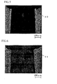
- Dross occurred in the through hole of the wire for I-shape oil rings is mainly produced around the outlet of the through hole 2, that is, a region which surrounds the outlet in a piercing direction as shown in Fig. 2 .
- the dross 3 occurred, as shown in Fig. 2 , around the outlet of the through hole 2 is remelted to be integrated with the wire thereby restraining the dross from exfoliation resulting in a harmless dross.
- the remelted and solidified portion formed on the wire for I-shape oil rings is required to exceed a melted and solidified region around the through hole when viewing a cross section of the wire taken along an axis of the through hole. Dross is frequently formed along a melted and solidified portion formed on the through hole and when the remelting portion does not exceed the melted and solidified portion, it is insufficient to inhibit dross from exfoliation and to have dross made integral with a wire. Also, since there is a risk that when the remelting portion excessively extends, toughness is adversely affected, it is preferred that the remelted and solidified portion be formed to have 200 ⁇ m or less from the outer circumference of the through hole.
- the remelted and solidified portion be formed to have 100 ⁇ m or less in the depth direction of the through hole.
- the remelted and solidified portion of a through hole and a thermally affecting layer formed with formation of the melting portion are preferably as thin as possible since toughness is adversely affected thereby.
- influences of formation of a remelted and solidified portion on strength and toughness of a wire is prescribed in terms of cross section since they are large in a width direction (direction of wire diameter).
- the remelting portion excessively extends in a length direction of a wire, however, there is a risk that strength and toughness are adversely affected.
- the remelting portion preferably has 500 ⁇ m or less from the outer circumference of the through hole also in the length direction of a wire.
- the through hole is liable to be shaped large on an incidence side of laser and small on an outgoing side. Therefore, a remelted and solidified portion is actually formed on a side, on which a through hole is small in diameter.
- the through holes in the wire for I-shape oil rings is preferably formed in a direction from a smaller opening angle side toward a larger opening angle side of the wire when viewing a cross section of the wire.
- molten metal is occasionally blown off by assist gas.
- assist gas By setting a piercing direction from a smaller opening angle side toward a larger opening angle side of the wire, it is possible to make the wire distant from a scattered region of sputter, thus enabling reducing a risk that sputter adheres to the wire.
- assist gas at high pressure of 0.2 MPa or higher in order to blow off a molten metal.
- projections on upper and lower surfaces of the through hole be 30 ⁇ m or less in height. This is because of a risk that being over 30 ⁇ m, the projections obstruct oil flow when a wire is used as an oil ring and of a possibility that the inherent performance of an oil ring is impeded.
- a projection which is provided on a remelted and solidified portion formed around the through hole, 30 ⁇ m or less in height, it is possible to ensure flowability of oil required as a function of an oil ring.
- the height of a projection enables adjusting the injection pressure of assist gas, a nozzle position, laser power, defocusing, or the like and exercising control to 30 ⁇ m or less while keeping the through hole in shape.
- a method of manufacturing an I-shape oil ring material comprises a piercing process of piercing the through hole by means of laser and a remelted and solidified portion forming process of forming a remelted and solidified portion, which encloses an exit of the through hole, on an outlet side of the through hole.
- the piercing process and the remelted and solidified portion forming process may be conducted in separate process lines, they are preferably arranged successively in the same process line since it is possible to accurately form a remelted and solidified portion around the through hole formed in the piercing process and to reduce the possibility that dross is left.
- a method of manufacturing a wire for I-shape oil rings preferably comprises an oil applying process, in which oil is applied to at least a surface of the wire for I-shape oil rings, on which a through hole is formed, prior to the piercing process.
- the piercing process in the invention preferably comprises a preliminary piercing process of piercing holes each having a smaller dimension than a predetermined dimension, and a finish piercing process of piercing holes each having a predetermined dimension.
- holes subjected to piercing in the preliminary piercing process be shaped to make adhesion of dross and sputter hard and kept in shape, the holes being preferably smaller in length and width than holes formed in the finish piercing process. Also, both centers of holes being subjected to piercing in the preliminary piercing process and holes being subjected to piercing in the finish piercing process are preferably present at a width center of the wire.
- Penetration is not necessarily required in the preliminary piercing process.
- a surface of a web section, on which a remelted and solidified portion is formed can be subjected to blasting subsequently to the remelted and solidified portion forming process.
- blasting By subjecting a surface, on which a remelted and solidified portion is formed, to blasting, without deformation of the wire, sputter, oil content, etc. adhered on the wire are removed, and it is possible to obtain a predetermined surface roughness.
- a predetermined surface roughness on a surface of a wire for I-shape oil rings according to the invention, it is possible to expect an improvement in a force, by which an oil film needed as a function of an oil ring is held.
- media, processing pressure, etc. in blasting in the invention can be appropriately selected according to specifications of a product depending upon a configuration of adhesion of an object, which adheres to a wire and should be removed.
- a wire for I-shape oil rings shown in Specimen 1 in TABLE 1
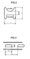
- a slot-like oil hole in which a width 7, a length 8, and a pitch 9 shown in Fig. 4 are indicated in TABLE 1
- a remelted and solidified portion for making dross harmless was formed by laser processing. Details will be described below.
- an oil applying process, a preliminary piercing process, a finish piercing process, a remelted and solidified portion forming process, and a wet blasting machine were arranged straight along a running line of a wire.
- a wire for I-shape oil rings used in the experiment, a wire, in which a width 4, a thickness 5, and a web thickness 6 shown in Fig. 4 are indicated in TABLE 1, was prepared, and first, while the wire was caused to run in a posture, in which a R surface was directed upward as shown in Fig. 3 , oil was applied to a surface, on which a through hole of the wire was to be formed.
- pulse YAG laser having a power of 2.0 kW and a smaller spot diameter than that used for piercing of a predetermined dimension was irradiated toward a web from above the R surface shown in Fig. 3 for a shorter period of time than that required for piercing of a predetermined dimension in a manner to be focused approximately into a web medium point, and nitrogen gases having a pressure of 0.7 MPa were jetted to form a smaller through hole than a hole of a predetermined dimension.
- pulse YAG laser having a power shown in TABLE 1 and a spot diameter of 0.45 mm was irradiated, as shown in Fig. 3 , from the upper side, with a round surface having a broader opening angle when viewing a cross section of the wire, toward the web section, for 2 ms so as to be focused approximately on a midpoint of the web section, and simultaneously nitrogen gases having a pressure of 0.7 MPa were jetted to form through holes.
- dross 10 partially projecting from a base material and involving the risk of exfoliation, adhered on an outlet side of the through hole. Also, it was confirmed that no sputter adhered to the wire.
- pulse YAG laser having a power shown in TABLE 1 was irradiated to a region covering that portion at an exit of the through hole, on which dross was generated, for 3.0 ms, and nitrogen gases having a pressure of 0.03 MPa were jetted as assist gas to remelt and solidify the dross again.
- the results are shown in Fig. 19 and TABLE 2.
- a remelted and solidified portion depth shown in TABLE 2 was measured from a side of the through hole in a direction along a width 4 of a molten portion.
- a remelted and solidified portion 11 was formed exceeding a molten portion formed on the through hole in the direction along the width 4 when viewed in a cross section about a center of the through hole.
- the remelted and solidified portion was formed to have 100 ⁇ m or less from an outer periphery of an exit of the through hole in the direction along the width 4 and 30 ⁇ m or less from in a depth direction of the through hole, that is, a direction along a depth 5.
- a wire for I-shape oil rings was caused to run reversely to that in Fig. 3 , that is, in a posture, in which a rail surface was directed upward, to fabricate a wire for I-shape oil rings going through an oil applying process, a preliminary piercing process, a finish piercing process, and a remelted and solidified portion forming process in the same manner as in Specimen 1.
- 10 Cr steel in Specimen 4 shown in TABLE 1 and TABLE 2 is one containing, by mass %, 0.5 % of C, 0.2 % of Si, 0.3 % of Mn, 10 % of Cr, the balance being Fe, and unavoidable impurities.
- a wire was caused to run in a posture, in which a R surface was directed upward as shown in Fig. 3 , and laser was irradiated toward a web from under a rail surface under the conditions shown in TABLE 1 to form through holes by melting.
- a wire for I-shape oil rings was caused to run in a posture, in which a R surface was directed upward as shown in Fig. 3 , and laser was irradiated toward a web from a lower side having a smaller opening angle when viewing a cross section of the wire, under the conditions shown in TABLE 1 to form through holes.
- the results of Specimen 2 are shown in Fig. 7 .
Landscapes
- Engineering & Computer Science (AREA)
- Mechanical Engineering (AREA)
- Physics & Mathematics (AREA)
- Optics & Photonics (AREA)
- Plasma & Fusion (AREA)
- General Engineering & Computer Science (AREA)
- Chemical & Material Sciences (AREA)
- Combustion & Propulsion (AREA)
- Pistons, Piston Rings, And Cylinders (AREA)
- Laser Beam Processing (AREA)
- Reinforcement Elements For Buildings (AREA)
Abstract
Description
- The present invention relates to a wire for H- or I-shaped oil rings having left and right rail sections and a web section connecting the left and right rail sections with each other, and a producing method thereof.
- Conventionally, an I-shape wire used for producing oil rings mounted on pistons of internal combustion engines has been provided with oil holes I-shape by stamping. In order to conduct piercing by stamping, it is necessary to prepare dies corresponding to individual product specifications.
- In contrast, as disclosed in Patent Document 1 (see below), laser beam processing has been proposed as means for formation of oil holes in an I-shape oil wire. In order to form oil holes, the technique shown in
Patent Document 1 does not need preparing dies corresponding to individual product specifications, and is advantageous in enabling formation of optional hole shapes and hole pitches by means of laser beam processing. - The method of producing steel oil rings shown in
Patent Document 1 is advantageous in reduction of man-hour for piercing but involves a problem that solidified residues (herein below referred to as dross) generated by laser beam processing adhere to a surface of profile wires. When the dross remains, there is a risk that during operation of engines, the dross exfoliated from the oil rings is mixed in engine lubricant oil as a metal lump thereby damaging a cylinder wall. - In order to improve the influence of dross adhesion,
Patent Document 2 discloses to use a high thermal energy density processing method (including the YAG laser method) together with an assist gas of oxygen or air, as heating means. Also, the document teaches to reheat the dross and blow out it at a backside of the wire.Patent Document 2 further teaches an effectiveness of a method of removing dross in inline by means of scrubbing (i.e. grinding, cutting or chipping) as measures against the dross problem. - Patent Document 1:
JP-A-3-260473 - Patent Document 2:
JP-A-9-159025 - While
Patent Document 2 discloses the technique of melting the dross adhered on the surface of the wire to blow out the same with high pressure gas, even if slag is removed from around a hole, there is a risk that the slag adheres again in another location on the surface, or passes through the hole to adhere to a back surface of the wire, so that the technique lacks reliability. - Also, when thermal energy and gas pressure being sufficient to blow out the dross formed on a through hole are exerted, there is a risk that a shape of the through hole is not conformity with a predetermined shape thereby making the wire to lose a performance as an oil ring.
- Accordingly it is an object of the present invention to reduce the influence of the dross in a wire for I-shape oil rings and a manufacturing method thereof, and to provide the wire for an I-shape oil ring, which wire has oil holes with a predetermined shape and dimensions, and the manufacturing method thereof.
- The present inventors found out that it is possible to reduce the influence of dross and obtain oil holes each having a predetermined shape by forming a predetermined remelting portion at an outlet side of each of the oil holes, which are through holes, formed by melting, of a wire for I-shape oil rings.
- According to a first aspect of the invention, there is provided:
- a wire for I-shape oil rings, comprising a left and a right rail sections, and a web section connecting the rail sections with each other and having oil holes as through holes formed by melting, the wire having a diameter of not more than 10 mm which is defined by a circle circumscribing a contour of a cross section of the wire,
- wherein there is formed a remelted and solidified portion surrounding an outlet of each of the through holes,
- wherein the remelted and solidified portion is formed so as to exceed a melted and solidified region around the through hole but not to exceed 200µm from the periphery of the through hole, when viewing a cross section of the wire taken along the axis of the through hole, and
- wherein the remelted and solidified portion is formed so as not to exceed 100µm in a depth direction from the outlet of the through hole.
- Preferably, the through holes are formed in a direction from a smaller opening angle side toward a larger opening angle side of the wire when viewing a cross section of the wire.
- Preferably, a height of projections of the through hole on upper and lower surfaces of the wire is not more than 30µm.
- According to a second aspect of the invention, the wire for I-shape oil rings can be produced by the method comprising the steps of:
- piercing the through holes by means of laser; and
- forming a remelted and solidified portion surrounding an outlet of each of the through holes by means of laser,
- wherein the remelted and solidified portion is formed so as to exceed a melted and solidified region around the through hole but not to exceed 200µm from the periphery of the through hole, when viewing a cross section of the wire taken along the axis of the through hole, and
- wherein the remelted and solidified portion is formed so as not to exceed 100µm in a depth direction from the outlet of the through hole.
- Preferably, the through holes are formed in a direction from a smaller opening angle side toward a larger opening angle side of the wire when viewing a cross section of the wire.
- Preferably, a height of projections of the through hole on upper and lower surfaces of the wire is not more than 30µm.
- Preferably, oil is applied to at least a surface section of the wire for I-shape oil rings, in which surface section a through hole is formed, prior to the piercing process.
- Preferably, the piercing process comprises a preliminary piercing step of piercing a through hole having a smaller size than a predetermined size, and a finishing step of piercing a through hole having the predetermined size.
- A surface of the web section formed with the remelted and solidified portion may be subjected to shot-blasting after forming the remelted and solidified portion.
- According to the invention, it is possible to reduce the influence of dross and to obtain an oil hole having a predetermined shape by forming the remelted and solidified portion on an outlet side of the oil hole, which is the through hole of the wire for I-shape oil rings.
-
-
Fig. 1 is a microphotograph showing an example of a surface state of a wire for I-shape oil rings, according to the invention; -
Fig. 2 is a microphotograph showing an example of a surface state after a through hole is formed by melting; -
Fig. 3 is a schematic view showing an example of the shape of a cross section of a wire for I-shape oil rings, according to the invention; -
Fig. 4 is a schematic view showing an example of a surface state of a wire for I-shape oil rings, according to the invention; -
Fig. 5 is a photograph showing the microstructure of a cross section of a wire, according to the invention, after a through hole is formed by melting; -
Fig. 6 is a photograph showing the microstructure of a cross section of a wire, according to the invention, after a remelted and solidified portion is formed; -
Fig. 7 is a microphotograph showing a cross section of a wire, according to the invention, after forming a through hole by melting; -
Fig. 8 is a photograph showing the microstructure of a cross section of a wire, according to the invention, after forming a remelted and solidified portion; and -
Fig. 9 is a microphotograph showing an appearance of a wire with one surface side, on which a remelted and solidified portion is formed, and which was subjected to shot-blasting. - With a wire for I-shape oil rings, according to the invention, there is formed a remelted and solidified portion surrounding an outlet of each of the through holes. The remelted and solidified portion is formed so as to exceed a melted and solidified region around the through hole but not to exceed 200µm from the periphery of the through hole, when viewing a cross section of the wire taken along the axis of the through hole. Further, the remelted and solidified portion is formed so as not to exceed 100µm in a depth direction from the outlet of the through hole.
- Dross occurred in the through hole of the wire for I-shape oil rings is mainly produced around the outlet of the through
hole 2, that is, a region which surrounds the outlet in a piercing direction as shown inFig. 2 . According to the invention, since the remelted and solidifiedportion 1 is formed around the outlet of the throughhole 2 as shown inFig. 1 , thedross 3 occurred, as shown inFig. 2 , around the outlet of thethrough hole 2 is remelted to be integrated with the wire thereby restraining the dross from exfoliation resulting in a harmless dross. - The remelted and solidified portion formed on the wire for I-shape oil rings, according to the invention, is required to exceed a melted and solidified region around the through hole when viewing a cross section of the wire taken along an axis of the through hole. Dross is frequently formed along a melted and solidified portion formed on the through hole and when the remelting portion does not exceed the melted and solidified portion, it is insufficient to inhibit dross from exfoliation and to have dross made integral with a wire. Also, since there is a risk that when the remelting portion excessively extends, toughness is adversely affected, it is preferred that the remelted and solidified portion be formed to have 200 µm or less from the outer circumference of the through hole. Also, since there is a risk that when the remelted and solidified portion is too deep in the depth direction, toughness is adversely affected, it is preferred that the remelted and solidified portion be formed to have 100µm or less in the depth direction of the through hole. In addition, the remelted and solidified portion of a through hole and a thermally affecting layer formed with formation of the melting portion are preferably as thin as possible since toughness is adversely affected thereby.
- In the invention, influences of formation of a remelted and solidified portion on strength and toughness of a wire is prescribed in terms of cross section since they are large in a width direction (direction of wire diameter). When the remelting portion excessively extends in a length direction of a wire, however, there is a risk that strength and toughness are adversely affected. Accordingly, the remelting portion preferably has 500 µm or less from the outer circumference of the through hole also in the length direction of a wire.
- In addition, the through hole is liable to be shaped large on an incidence side of laser and small on an outgoing side. Therefore, a remelted and solidified portion is actually formed on a side, on which a through hole is small in diameter.
- The through holes in the wire for I-shape oil rings, according to the invention, is preferably formed in a direction from a smaller opening angle side toward a larger opening angle side of the wire when viewing a cross section of the wire.
- When the through holes are formed in the wire for I-shape oil rings, molten metal is occasionally blown off by assist gas. At this time, there is a possibility that flying molten metal (i.e. sputtering) adheres again to the wire. By setting a piercing direction from a smaller opening angle side toward a larger opening angle side of the wire, it is possible to make the wire distant from a scattered region of sputter, thus enabling reducing a risk that sputter adheres to the wire. In a piercing process, it is preferable to apply assist gas at high pressure of 0.2 MPa or higher in order to blow off a molten metal.
- Also, in a remelted and solidified portion forming process, sufficient pressure to blow off dross, used in the piercing process, is not needed but the use of assist gas at 0.05 MPa or lower is preferable with a view to having dross remelted and solidified and staying there.
- It is preferred that projections on upper and lower surfaces of the through hole be 30µm or less in height. This is because of a risk that being over 30µm, the projections obstruct oil flow when a wire is used as an oil ring and of a possibility that the inherent performance of an oil ring is impeded. By making a projection, which is provided on a remelted and solidified portion formed around the through hole, 30µm or less in height, it is possible to ensure flowability of oil required as a function of an oil ring.
- In addition, the height of a projection enables adjusting the injection pressure of assist gas, a nozzle position, laser power, defocusing, or the like and exercising control to 30µm or less while keeping the through hole in shape.
- A method of manufacturing an I-shape oil ring material, according to the invention, comprises a piercing process of piercing the through hole by means of laser and a remelted and solidified portion forming process of forming a remelted and solidified portion, which encloses an exit of the through hole, on an outlet side of the through hole.
- While the piercing process and the remelted and solidified portion forming process may be conducted in separate process lines, they are preferably arranged successively in the same process line since it is possible to accurately form a remelted and solidified portion around the through hole formed in the piercing process and to reduce the possibility that dross is left.
- A method of manufacturing a wire for I-shape oil rings, according to the invention, preferably comprises an oil applying process, in which oil is applied to at least a surface of the wire for I-shape oil rings, on which a through hole is formed, prior to the piercing process. By applying oil to at least a surface of the wire for I-shape oil rings, on which a through hole is formed, it is possible to reduce adhesion of sputter generated in the piercing process. Also, by applying oil also to an outlet side of the through hole, it is possible to use assist gas to reduce adhesion of sputter scattered over an exit surface of the through hole.
- This is because oil applied to the wire prevents sputter from coming into direct contact with a wire surface.
- The piercing process in the invention preferably comprises a preliminary piercing process of piercing holes each having a smaller dimension than a predetermined dimension, and a finish piercing process of piercing holes each having a predetermined dimension. By piercing through holes by melting in two or more stages, it is possible to reduce dross generated in the finish piercing process and a scattering quantity of sputter.
- It is required that holes subjected to piercing in the preliminary piercing process be shaped to make adhesion of dross and sputter hard and kept in shape, the holes being preferably smaller in length and width than holes formed in the finish piercing process. Also, both centers of holes being subjected to piercing in the preliminary piercing process and holes being subjected to piercing in the finish piercing process are preferably present at a width center of the wire.
- Penetration is not necessarily required in the preliminary piercing process.
- In the method of manufacturing a wire for I-shape oil rings, according to the invention, that surface of a web section, on which a remelted and solidified portion is formed, can be subjected to blasting subsequently to the remelted and solidified portion forming process. By subjecting a surface, on which a remelted and solidified portion is formed, to blasting, without deformation of the wire, sputter, oil content, etc. adhered on the wire are removed, and it is possible to obtain a predetermined surface roughness. Also, by providing a predetermined surface roughness on a surface of a wire for I-shape oil rings, according to the invention, it is possible to expect an improvement in a force, by which an oil film needed as a function of an oil ring is held.
- Also, media, processing pressure, etc. in blasting in the invention can be appropriately selected according to specifications of a product depending upon a configuration of adhesion of an object, which adheres to a wire and should be removed.
- According to the embodiments described above, while a wire for I-shape oil rings, shown in
Specimen 1 in TABLE 1, was caused to run continuously, a slot-like oil hole, in which awidth 7, alength 8, and apitch 9 shown inFig. 4 are indicated in TABLE 1, was formed on a web section of the wire by laser processing, and then a remelted and solidified portion for making dross harmless was formed by laser processing. Details will be described below. - First, in a laser processing equipment used in the invention, an oil applying process, a preliminary piercing process, a finish piercing process, a remelted and solidified portion forming process, and a wet blasting machine were arranged straight along a running line of a wire. For a wire for I-shape oil rings, used in the experiment, a wire, in which a
width 4, athickness 5, and aweb thickness 6 shown inFig. 4 are indicated in TABLE 1, was prepared, and first, while the wire was caused to run in a posture, in which a R surface was directed upward as shown inFig. 3 , oil was applied to a surface, on which a through hole of the wire was to be formed. - In the preliminary piercing process, pulse YAG laser having a power of 2.0 kW and a smaller spot diameter than that used for piercing of a predetermined dimension was irradiated toward a web from above the R surface shown in
Fig. 3 for a shorter period of time than that required for piercing of a predetermined dimension in a manner to be focused approximately into a web medium point, and nitrogen gases having a pressure of 0.7 MPa were jetted to form a smaller through hole than a hole of a predetermined dimension. - In the finish piercing process, pulse YAG laser having a power shown in TABLE 1 and a spot diameter of 0.45 mm was irradiated, as shown in
Fig. 3 , from the upper side, with a round surface having a broader opening angle when viewing a cross section of the wire, toward the web section, for 2 ms so as to be focused approximately on a midpoint of the web section, and simultaneously nitrogen gases having a pressure of 0.7 MPa were jetted to form through holes. At this time, it was confirmed that when only the through hole was formed as shown inFig. 5 ,dross 10, partially projecting from a base material and involving the risk of exfoliation, adhered on an outlet side of the through hole. Also, it was confirmed that no sputter adhered to the wire. - Subsequently, pulse YAG laser having a power shown in TABLE 1 was irradiated to a region covering that portion at an exit of the through hole, on which dross was generated, for 3.0 ms, and nitrogen gases having a pressure of 0.03 MPa were jetted as assist gas to remelt and solidify the dross again. The results are shown in Fig. 19 and TABLE 2. In addition, a remelted and solidified portion depth shown in TABLE 2 was measured from a side of the through hole in a direction along a
width 4 of a molten portion. - As shown in
Fig. 6 and TABLE 2, a remelted and solidified portion 11 was formed exceeding a molten portion formed on the through hole in the direction along thewidth 4 when viewed in a cross section about a center of the through hole. InSpecimen 1, it was confirmed that the remelted and solidified portion was formed to have 100µm or less from an outer periphery of an exit of the through hole in the direction along thewidth 4 and 30µm or less from in a depth direction of the through hole, that is, a direction along adepth 5. Thereby, it was possible to obtain a wire, in which dross 10 shown inFig. 5 and having the possibility of exfoliation as shown inFig. 5 was remelted and integrated with a base metal and the risk of dross falling off into an engine was eliminated. - At this time, it was confirmed that a height of a projection in the direction along the
depth 5 was 15µm at maximum on the outlet side of the through hole, that is, on the remelted and solidified portion and 0 µm on an incidence side of the through hole, and a periphery of the through hole was made smooth. Thereby, it can be expected to ensure oil flowability required as a function of an oil ring. - Subsequently, under the conditions of
Specimens 2 to 4 in TABLE 1, a wire for I-shape oil rings was caused to run reversely to that inFig. 3 , that is, in a posture, in which a rail surface was directed upward, to fabricate a wire for I-shape oil rings going through an oil applying process, a preliminary piercing process, a finish piercing process, and a remelted and solidified portion forming process in the same manner as inSpecimen 1. In addition, 10 Cr steel inSpecimen 4 shown in TABLE 1 and TABLE 2 is one containing, by mass %, 0.5 % of C, 0.2 % of Si, 0.3 % of Mn, 10 % of Cr, the balance being Fe, and unavoidable impurities. - In the preliminary piercing process, a wire was caused to run in a posture, in which a R surface was directed upward as shown in
Fig. 3 , and laser was irradiated toward a web from under a rail surface under the conditions shown in TABLE 1 to form through holes by melting. - Subsequently, in the finish piercing process, a wire for I-shape oil rings was caused to run in a posture, in which a R surface was directed upward as shown in
Fig. 3 , and laser was irradiated toward a web from a lower side having a smaller opening angle when viewing a cross section of the wire, under the conditions shown in TABLE 1 to form through holes. As a specific example, the results ofSpecimen 2 are shown inFig. 7 . - It was confirmed that when only a through hole was formed as shown in
Fig. 7 , dross 12, involving the risk of exfoliation, adhered on an outlet side of the through hole. Also, at this time, it was confirmed that sputter did not adhere to the wire. - Subsequently, a wire was caused to run in a posture, in which a R surface shown in
Fig. 3 was directed upward, and a remelted and solidified portion was formed at an exit of the through hole under the same conditions as those inSpecimen 1. The results forSpecimen 2 are shown inFig. 8 and TABLE 2, and the results for the rest are shown in a lump in TABLE 2. In addition, the respective measurements were made in the same manner as inSpecimen 1. - As shown in
Fig. 8 and TABLE 2, it could be confirmed also inSpecimens 2 to 4 that there was obtained a wire, in which dross 12 was remelted and integrated with a base material to form a remelted and solidified portion 13 and so the risk of dross falling off into an engine was eliminated in the same manner as inSpecimen 1. - Succeeding the remelted and solidified portion forming process in
Specimen 2 shown in TABLE 1, a wet blasting machine mounted in an inline manner was used to subject that surface side of the web, on which a remelted and solidified portion was formed, to blasting of slurry having a concentration of 20 % with a delivery gun under the conditions of a wire inbetween distance of 20 mm and air pressure of 0.5 MPa. The results are shown inFig. 9 . - As shown in
Fig. 9 , it was confirmed that oil content was removed without marring the shape of a product. At this time, the surface roughness of a wire was Rz1.5µm. Thereby, it is possible to expect an improvement in a force, by which an oil film needed as a function of an oil ring is held.TABLE 1 MATERIAL CROSS SECTIONAL DIMENSION OF WIRE DIMENSION OF HOLE (INCIDENCE SIDE) INCIDENCE SURFACE IN PIERCING PROCESS LASER POWER IN PIERCING PROCESS
(kW)LASER POWER IN REMELTED AND SOLIDIFIED PORTION FORMING PROCESS
(kW)ASSIST GAS PRESSURE IN PIERCING PROCESS
(MPa)ASSIST GAS PRESSURE IN REMELTED AND SOLIDIFIED PORTION FORMING PROCESS
(MPa)WIDHT X THICKNESS X WEB THICKNESS
(mm)PITCH
(mm)LENGTH
(mm)WIDTH
(mm)SPECIMEN 1CORRESPONDING TO SUS420J2 1.5×2.0×0.5 5 0.90 0.55 R SURFACE 5.5 0.7 0.7 0.035 SPECIMEN 2CORRESPONDING TO SUS420J2 1.5×2.0×0.5 5 0.90 0.55 RAIL SURFACE 5.5 0.7 0.7 0.030 SPECIMEN 3CORRESPONDING TO SUS420J2 1.5×1.7×0.4 7 1.30 0.50 RAIL SURFACE 3.5 0.8 0.7 0.025 SPECIMEN 410Cr STEEL 2.0×2.0×0.45 5 1.20 0.55 RAIL SURFACE 5.0 0.7 0.7 0.030 *NOTES: WIRES USED IN SPECIMENS 1 TO 3 CORRESPOND TO JIS SUS420J2TABLE 2 MATERIAL DEPTH OF MELTED AND SOLIDIFIED PORTION
(µm)WIDTH OF REMELTED AND SOLIDIFIED PORTION
(µm)DEPTH OF REMELTED AND SOLIDIFIED PORTION
(µm)HEIGHT OF BURR
(µm)SURFACE ROUGHNESS OF WEB
(µm)MAXIMUM AVERAGE MAXIMUM AVERAGE MAXIMUM AVERAGE MAXIMUM Rz SPECIMEN 1 CORRESPONDING TO SUS420J2 22.8 22.5 75 57 29.2 19.1 15 0.4 SPECIMEN 2CORRESPONDING TO SUS420J2 24.4 22.7 120 110 48.0 47.4 30 1.5 SPECIMEN 3CORRESPONDING TO SUS420J2 15.4 15.3 80 75 48.8 37.7 14 0.4 SPECIMEN 410Cr STEEL 12.6 11.3 130 120 24.5 23.1 20 0.4 * NOTES: WIRES USED IN SPECIMENS 1 TO 3 CORRESPOND TO JIS SUS420J2. -
- 1, 11 and 13: remelted and solidified portions
- 2: a through hole formed by melting
- 3, 10 and 12: dross
- 4: a width
- 5: a thickness
- 6: a thickness of a web
- 7: a width
- 8: a length
- 9: a pitch of the through holes
Claims (11)
- A wire for I-shape oil rings, comprising:a left and a right rail sections, and a web section connecting the rail sections with each other and having oil holes as through holes formed by melting, the wire having a diameter of not more than 10 mm which is defined by a circle circumscribing a contour of a cross section of the wire,wherein there is formed a remelted and solidified portion surrounding an outlet of each of the through holes,wherein the remelted and solidified portion is formed so as to exceed a melted and solidified region around the through hole but not to exceed 200µm from the periphery of the through hole, when viewing a cross section of the wire taken along the axis of the through hole, andwherein the remelted and solidified portion is formed so as not to exceed 100µm in a depth direction from the outlet of the through hole.
- The wire for I-shape oil rings, according to claim 1, wherein the through holes are formed in a direction from a smaller opening angle side toward a larger opening angle side of the wire when viewing a cross section of the wire.
- The wire for I-shape oil rings, according to claim 1, wherein a height of projections of the through hole on upper and lower surfaces of the wire is not more than 30µm.
- The wire for I-shape oil rings, according to claim 2, wherein a height of projections of the through hole on upper and lower surfaces of the wire is not more than 30µm.
- A method of producing a wire for I-shape oil rings, which wire comprises a left and a right rail sections, and a web section connecting the rail sections with each other, has oil holes as through holes formed by melting, and has a diameter of not more than 10 mm which is defined by a circle circumscribing a contour of a cross section of the wire,
wherein the method comprises the steps of:piercing the through holes by means of laser; andforming a remelted and solidified portion surrounding an outlet of each of the through holes by means of laser,wherein the remelted and solidified portion is formed so as to exceed a melted and solidified region around the through hole but not to exceed 200µm from the periphery of the through hole, when viewing a cross section of the wire taken along the axis of the through hole, andwherein the remelted and solidified portion is formed so as not to exceed 100µm in a depth direction from the outlet of the through hole. - The method of manufacturing a wire for I-shape oil rings, according to claim 5, wherein the through holes are formed in a direction from a smaller opening angle side toward a larger opening angle side of the wire when viewing a cross section of the wire.
- The method of manufacturing a wire for I-shape oil rings, according to claim 5, wherein a height of projections of the through hole on upper and lower surfaces of the wire is not more than 30µm.
- The method of manufacturing a wire for I-shape oil rings, according to claim 6, wherein a height of projections of the through hole on upper and lower surfaces of the wire is not more than 30µm.
- The method of manufacturing a wire for I-shape oil rings, according to any one of claims 5 to 8, further comprising the step of applying oil to at least a surface section of the wire for I-shape oil rings, in which surface section a through hole is formed, prior to the piercing process.
- The method of manufacturing a wire for I-shape oil rings, according to any one of claims 5 to 9, wherein the step of the piercing comprises a preliminary piercing step of piercing a through hole having a smaller size than a predetermined size, and a finishing step of piercing a through hole having the predetermined size.
- The method of manufacturing a wire for I-shape oil rings, according to any one of claims 5 to 10, wherein after forming the remelted and solidified portion, a surface of the web section formed with the remelted and solidified portion is subjected to shot-blasting treatment.
Applications Claiming Priority (3)
| Application Number | Priority Date | Filing Date | Title |
|---|---|---|---|
| JP2007154000 | 2007-06-11 | ||
| JP2008089880 | 2008-03-31 | ||
| PCT/JP2008/060649 WO2008153041A1 (en) | 2007-06-11 | 2008-06-11 | Wire rod for i-type oil ring, and its manufacturing method |
Publications (3)
| Publication Number | Publication Date |
|---|---|
| EP2169281A1 true EP2169281A1 (en) | 2010-03-31 |
| EP2169281A4 EP2169281A4 (en) | 2016-11-09 |
| EP2169281B1 EP2169281B1 (en) | 2018-05-09 |
Family
ID=40129646
Family Applications (1)
| Application Number | Title | Priority Date | Filing Date |
|---|---|---|---|
| EP08765428.1A Active EP2169281B1 (en) | 2007-06-11 | 2008-06-11 | Wire rod for i-type oil ring, and its manufacturing method |
Country Status (7)
| Country | Link |
|---|---|
| US (2) | US9267461B2 (en) |
| EP (1) | EP2169281B1 (en) |
| JP (1) | JP4947446B2 (en) |
| KR (1) | KR101217005B1 (en) |
| CN (1) | CN102317659B (en) |
| PT (1) | PT2169281T (en) |
| WO (1) | WO2008153041A1 (en) |
Families Citing this family (3)
| Publication number | Priority date | Publication date | Assignee | Title |
|---|---|---|---|---|
| WO2011132679A1 (en) * | 2010-04-19 | 2011-10-27 | 日本ピストンリング株式会社 | Oil ring for internal combustion engine |
| JP2019211001A (en) * | 2018-06-04 | 2019-12-12 | 大豊工業株式会社 | Slide bearing |
| JP7148667B1 (en) * | 2021-03-31 | 2022-10-05 | Tpr株式会社 | oil control ring |
Family Cites Families (12)
| Publication number | Priority date | Publication date | Assignee | Title |
|---|---|---|---|---|
| US3467397A (en) * | 1968-03-13 | 1969-09-16 | Nippon Piston Ring Co Ltd | Oil scraping ring combined with coiled expander |
| JPH03260473A (en) | 1990-03-08 | 1991-11-20 | Riken Corp | Manufacture of steel oil ring |
| DE69307823T2 (en) * | 1992-10-23 | 1997-09-11 | Hitachi Metals Co. Ltd., Tokio/Tokyo | Steel wire for an oil ring and process for its manufacture |
| JPH09159025A (en) * | 1995-12-08 | 1997-06-17 | Hitachi Metals Ltd | Through hole boring method for deformed wire member with groove for ol ring in internal combustion engine |
| JP2001219285A (en) | 2000-02-10 | 2001-08-14 | Nippon Steel Corp | Laser cutting method for steel materials |
| WO2002076666A2 (en) * | 2001-03-22 | 2002-10-03 | Xsil Technology Limited | A laser machining system and method |
| GB0112234D0 (en) * | 2001-05-18 | 2001-07-11 | Welding Inst | Surface modification |
| EP1295647A1 (en) * | 2001-09-24 | 2003-03-26 | The Technology Partnership Public Limited Company | Nozzles in perforate membranes and their manufacture |
| JP3925169B2 (en) * | 2001-11-26 | 2007-06-06 | 株式会社デンソー | Method and apparatus for simultaneous simultaneous melting of materials by laser light |
| KR100970241B1 (en) * | 2005-06-07 | 2010-07-16 | 닛산 다나카 가부시키가이샤 | Laser Piercing Method and Processing Equipment |
| JP2007057008A (en) * | 2005-08-25 | 2007-03-08 | Hitachi Metals Ltd | Method for manufacturing cross-sectionally deformed wire-rod pierced with through-hole |
| US20090057282A1 (en) * | 2007-08-15 | 2009-03-05 | Chunfu Huang | Laser machining method utilizing variable inclination angle |
-
2008
- 2008-06-11 JP JP2009519268A patent/JP4947446B2/en active Active
- 2008-06-11 WO PCT/JP2008/060649 patent/WO2008153041A1/en not_active Ceased
- 2008-06-11 CN CN200880019809.1A patent/CN102317659B/en active Active
- 2008-06-11 US US12/663,952 patent/US9267461B2/en active Active
- 2008-06-11 EP EP08765428.1A patent/EP2169281B1/en active Active
- 2008-06-11 PT PT87654281T patent/PT2169281T/en unknown
- 2008-06-11 KR KR1020097025068A patent/KR101217005B1/en active Active
-
2015
- 2015-11-16 US US14/942,070 patent/US9409257B2/en active Active
Non-Patent Citations (1)
| Title |
|---|
| See references of WO2008153041A1 * |
Also Published As
| Publication number | Publication date |
|---|---|
| US9267461B2 (en) | 2016-02-23 |
| PT2169281T (en) | 2018-08-03 |
| CN102317659B (en) | 2016-10-12 |
| US20160067831A1 (en) | 2016-03-10 |
| US20100181731A1 (en) | 2010-07-22 |
| WO2008153041A1 (en) | 2008-12-18 |
| KR20100004116A (en) | 2010-01-12 |
| JP4947446B2 (en) | 2012-06-06 |
| US9409257B2 (en) | 2016-08-09 |
| EP2169281A4 (en) | 2016-11-09 |
| CN102317659A (en) | 2012-01-11 |
| EP2169281B1 (en) | 2018-05-09 |
| KR101217005B1 (en) | 2012-12-31 |
| JPWO2008153041A1 (en) | 2010-08-26 |
Similar Documents
| Publication | Publication Date | Title |
|---|---|---|
| EP2036655B1 (en) | Method for manufacturing cast iron member, cast iron member, and engine for vehicle | |
| DE60131034T3 (en) | COOLED CASTING ROLL FOR THE CONTINUOUS CONTINUOUS CASTING OF THIN PRODUCTS AND CONTINUOUS CASTING METHOD | |
| EP2682490A1 (en) | Metal plate for laser processing and method for producing stainless steel plate for laser processing | |
| JP2007500782A (en) | Press-hardened parts and manufacturing method thereof | |
| CN1829816A (en) | Method for manufacturing hardened parts from sheet steel | |
| Oh et al. | Effect of in-situ heat treatments on deposition characteristics and mechanical properties for repairs using laser melting deposition | |
| US9409257B2 (en) | Wire for I-shape oil rings and producing method of the same | |
| CN106715005A (en) | Titanium slab for hot rolling with excellent surface properties after hot rolling even if rough rolling process and finishing process are omitted, and production method thereof | |
| CN114945699A (en) | Method for producing surface-tempered and surface-finished steel sheet | |
| CN101099975A (en) | Method for manufacturing two-layer surface composite steel | |
| CN1788101A (en) | Tool steel for hot working, tool for hot working and plug for producing seamless pipe | |
| CN101104178A (en) | Method for manufacturing composite strip steel for wood blade | |
| EP3613873B1 (en) | Dynamically impacting method for simultaneously peening and film-forming on substrate as bombarded by metallic glass particles | |
| CN109371336A (en) | Iron-based alloy powder for ultra-high-strength and toughness dual-phase laser forming and preparation method thereof, and preparation method of ultra-high-strength and tough forming layer | |
| KR100867277B1 (en) | Method for repairing tire mold using cold spray technology | |
| RU2700441C1 (en) | Method of producing copper-nickel coating on surfaces of titanium plate | |
| CN100558916C (en) | Stainless steel plate for gasket and its manufacturing method | |
| WO2024070987A1 (en) | Fe-based alloy, alloy member, product, and method for producing alloy member | |
| JP2000273653A (en) | Method for modifying surface of metal member and metal member having modified layer | |
| US20230074335A1 (en) | Composite structure with aluminum-based alloy layer containing boron carbide and manufacturing method thereof | |
| JP2021159993A (en) | Building-up method for metallic member, and metallic member | |
| JP2010216628A (en) | Wire for oil ring | |
| CN117282982B (en) | A low-cost, easy-to-cut, medium-strength titanium alloy parts rapid prototyping method | |
| JP7798238B2 (en) | Fe-based alloy, alloy member, and method for manufacturing alloy member | |
| JP2785139B2 (en) | Composite roll for rolling and manufacturing method thereof |
Legal Events
| Date | Code | Title | Description |
|---|---|---|---|
| PUAI | Public reference made under article 153(3) epc to a published international application that has entered the european phase |
Free format text: ORIGINAL CODE: 0009012 |
|
| 17P | Request for examination filed |
Effective date: 20100107 |
|
| AK | Designated contracting states |
Kind code of ref document: A1 Designated state(s): AT BE BG CH CY CZ DE DK EE ES FI FR GB GR HR HU IE IS IT LI LT LU LV MC MT NL NO PL PT RO SE SI SK TR |
|
| AX | Request for extension of the european patent |
Extension state: AL BA MK RS |
|
| DAX | Request for extension of the european patent (deleted) | ||
| RA4 | Supplementary search report drawn up and despatched (corrected) |
Effective date: 20161007 |
|
| RIC1 | Information provided on ipc code assigned before grant |
Ipc: B23K 26/354 20140101ALI20161003BHEP Ipc: F02F 5/00 20060101ALI20161003BHEP Ipc: F16J 9/06 20060101AFI20161003BHEP Ipc: B23K 26/14 20060101ALI20161003BHEP Ipc: B23K 26/00 20140101ALI20161003BHEP Ipc: B23K 37/08 20060101ALI20161003BHEP Ipc: B23K 31/02 20060101ALI20161003BHEP Ipc: B23K 26/16 20060101ALI20161003BHEP |
|
| GRAJ | Information related to disapproval of communication of intention to grant by the applicant or resumption of examination proceedings by the epo deleted |
Free format text: ORIGINAL CODE: EPIDOSDIGR1 |
|
| STAA | Information on the status of an ep patent application or granted ep patent |
Free format text: STATUS: GRANT OF PATENT IS INTENDED |
|
| GRAP | Despatch of communication of intention to grant a patent |
Free format text: ORIGINAL CODE: EPIDOSNIGR1 |
|
| INTG | Intention to grant announced |
Effective date: 20171129 |
|
| GRAS | Grant fee paid |
Free format text: ORIGINAL CODE: EPIDOSNIGR3 |
|
| GRAA | (expected) grant |
Free format text: ORIGINAL CODE: 0009210 |
|
| STAA | Information on the status of an ep patent application or granted ep patent |
Free format text: STATUS: THE PATENT HAS BEEN GRANTED |
|
| RAP1 | Party data changed (applicant data changed or rights of an application transferred) |
Owner name: HITACHI METALS, LTD. |
|
| AK | Designated contracting states |
Kind code of ref document: B1 Designated state(s): AT BE BG CH CY CZ DE DK EE ES FI FR GB GR HR HU IE IS IT LI LT LU LV MC MT NL NO PL PT RO SE SI SK TR |
|
| REG | Reference to a national code |
Ref country code: GB Ref legal event code: FG4D |
|
| REG | Reference to a national code |
Ref country code: CH Ref legal event code: EP Ref country code: AT Ref legal event code: REF Ref document number: 997862 Country of ref document: AT Kind code of ref document: T Effective date: 20180515 |
|
| REG | Reference to a national code |
Ref country code: DE Ref legal event code: R096 Ref document number: 602008055191 Country of ref document: DE Ref country code: IE Ref legal event code: FG4D |
|
| REG | Reference to a national code |
Ref country code: PT Ref legal event code: SC4A Ref document number: 2169281 Country of ref document: PT Date of ref document: 20180803 Kind code of ref document: T Free format text: AVAILABILITY OF NATIONAL TRANSLATION Effective date: 20180730 |
|
| REG | Reference to a national code |
Ref country code: NL Ref legal event code: MP Effective date: 20180509 |
|
| REG | Reference to a national code |
Ref country code: LT Ref legal event code: MG4D |
|
| PG25 | Lapsed in a contracting state [announced via postgrant information from national office to epo] |
Ref country code: BG Free format text: LAPSE BECAUSE OF FAILURE TO SUBMIT A TRANSLATION OF THE DESCRIPTION OR TO PAY THE FEE WITHIN THE PRESCRIBED TIME-LIMIT Effective date: 20180809 Ref country code: SE Free format text: LAPSE BECAUSE OF FAILURE TO SUBMIT A TRANSLATION OF THE DESCRIPTION OR TO PAY THE FEE WITHIN THE PRESCRIBED TIME-LIMIT Effective date: 20180509 Ref country code: FI Free format text: LAPSE BECAUSE OF FAILURE TO SUBMIT A TRANSLATION OF THE DESCRIPTION OR TO PAY THE FEE WITHIN THE PRESCRIBED TIME-LIMIT Effective date: 20180509 Ref country code: NO Free format text: LAPSE BECAUSE OF FAILURE TO SUBMIT A TRANSLATION OF THE DESCRIPTION OR TO PAY THE FEE WITHIN THE PRESCRIBED TIME-LIMIT Effective date: 20180809 Ref country code: ES Free format text: LAPSE BECAUSE OF FAILURE TO SUBMIT A TRANSLATION OF THE DESCRIPTION OR TO PAY THE FEE WITHIN THE PRESCRIBED TIME-LIMIT Effective date: 20180509 Ref country code: LT Free format text: LAPSE BECAUSE OF FAILURE TO SUBMIT A TRANSLATION OF THE DESCRIPTION OR TO PAY THE FEE WITHIN THE PRESCRIBED TIME-LIMIT Effective date: 20180509 |
|
| PG25 | Lapsed in a contracting state [announced via postgrant information from national office to epo] |
Ref country code: HR Free format text: LAPSE BECAUSE OF FAILURE TO SUBMIT A TRANSLATION OF THE DESCRIPTION OR TO PAY THE FEE WITHIN THE PRESCRIBED TIME-LIMIT Effective date: 20180509 Ref country code: NL Free format text: LAPSE BECAUSE OF FAILURE TO SUBMIT A TRANSLATION OF THE DESCRIPTION OR TO PAY THE FEE WITHIN THE PRESCRIBED TIME-LIMIT Effective date: 20180509 Ref country code: GR Free format text: LAPSE BECAUSE OF FAILURE TO SUBMIT A TRANSLATION OF THE DESCRIPTION OR TO PAY THE FEE WITHIN THE PRESCRIBED TIME-LIMIT Effective date: 20180810 Ref country code: LV Free format text: LAPSE BECAUSE OF FAILURE TO SUBMIT A TRANSLATION OF THE DESCRIPTION OR TO PAY THE FEE WITHIN THE PRESCRIBED TIME-LIMIT Effective date: 20180509 |
|
| REG | Reference to a national code |
Ref country code: AT Ref legal event code: MK05 Ref document number: 997862 Country of ref document: AT Kind code of ref document: T Effective date: 20180509 |
|
| PG25 | Lapsed in a contracting state [announced via postgrant information from national office to epo] |
Ref country code: RO Free format text: LAPSE BECAUSE OF FAILURE TO SUBMIT A TRANSLATION OF THE DESCRIPTION OR TO PAY THE FEE WITHIN THE PRESCRIBED TIME-LIMIT Effective date: 20180509 Ref country code: CZ Free format text: LAPSE BECAUSE OF FAILURE TO SUBMIT A TRANSLATION OF THE DESCRIPTION OR TO PAY THE FEE WITHIN THE PRESCRIBED TIME-LIMIT Effective date: 20180509 Ref country code: EE Free format text: LAPSE BECAUSE OF FAILURE TO SUBMIT A TRANSLATION OF THE DESCRIPTION OR TO PAY THE FEE WITHIN THE PRESCRIBED TIME-LIMIT Effective date: 20180509 Ref country code: AT Free format text: LAPSE BECAUSE OF FAILURE TO SUBMIT A TRANSLATION OF THE DESCRIPTION OR TO PAY THE FEE WITHIN THE PRESCRIBED TIME-LIMIT Effective date: 20180509 Ref country code: PL Free format text: LAPSE BECAUSE OF FAILURE TO SUBMIT A TRANSLATION OF THE DESCRIPTION OR TO PAY THE FEE WITHIN THE PRESCRIBED TIME-LIMIT Effective date: 20180509 Ref country code: DK Free format text: LAPSE BECAUSE OF FAILURE TO SUBMIT A TRANSLATION OF THE DESCRIPTION OR TO PAY THE FEE WITHIN THE PRESCRIBED TIME-LIMIT Effective date: 20180509 Ref country code: SK Free format text: LAPSE BECAUSE OF FAILURE TO SUBMIT A TRANSLATION OF THE DESCRIPTION OR TO PAY THE FEE WITHIN THE PRESCRIBED TIME-LIMIT Effective date: 20180509 |
|
| REG | Reference to a national code |
Ref country code: CH Ref legal event code: PL |
|
| REG | Reference to a national code |
Ref country code: DE Ref legal event code: R097 Ref document number: 602008055191 Country of ref document: DE |
|
| PG25 | Lapsed in a contracting state [announced via postgrant information from national office to epo] |
Ref country code: IT Free format text: LAPSE BECAUSE OF FAILURE TO SUBMIT A TRANSLATION OF THE DESCRIPTION OR TO PAY THE FEE WITHIN THE PRESCRIBED TIME-LIMIT Effective date: 20180509 |
|
| REG | Reference to a national code |
Ref country code: BE Ref legal event code: MM Effective date: 20180630 |
|
| PLBE | No opposition filed within time limit |
Free format text: ORIGINAL CODE: 0009261 |
|
| STAA | Information on the status of an ep patent application or granted ep patent |
Free format text: STATUS: NO OPPOSITION FILED WITHIN TIME LIMIT |
|
| REG | Reference to a national code |
Ref country code: IE Ref legal event code: MM4A |
|
| PG25 | Lapsed in a contracting state [announced via postgrant information from national office to epo] |
Ref country code: MC Free format text: LAPSE BECAUSE OF FAILURE TO SUBMIT A TRANSLATION OF THE DESCRIPTION OR TO PAY THE FEE WITHIN THE PRESCRIBED TIME-LIMIT Effective date: 20180509 Ref country code: LU Free format text: LAPSE BECAUSE OF NON-PAYMENT OF DUE FEES Effective date: 20180611 |
|
| 26N | No opposition filed |
Effective date: 20190212 |
|
| GBPC | Gb: european patent ceased through non-payment of renewal fee |
Effective date: 20180809 |
|
| PG25 | Lapsed in a contracting state [announced via postgrant information from national office to epo] |
Ref country code: FR Free format text: LAPSE BECAUSE OF NON-PAYMENT OF DUE FEES Effective date: 20180709 Ref country code: IE Free format text: LAPSE BECAUSE OF NON-PAYMENT OF DUE FEES Effective date: 20180611 Ref country code: LI Free format text: LAPSE BECAUSE OF NON-PAYMENT OF DUE FEES Effective date: 20180630 Ref country code: CH Free format text: LAPSE BECAUSE OF NON-PAYMENT OF DUE FEES Effective date: 20180630 |
|
| PG25 | Lapsed in a contracting state [announced via postgrant information from national office to epo] |
Ref country code: SI Free format text: LAPSE BECAUSE OF FAILURE TO SUBMIT A TRANSLATION OF THE DESCRIPTION OR TO PAY THE FEE WITHIN THE PRESCRIBED TIME-LIMIT Effective date: 20180509 Ref country code: BE Free format text: LAPSE BECAUSE OF NON-PAYMENT OF DUE FEES Effective date: 20180630 |
|
| PG25 | Lapsed in a contracting state [announced via postgrant information from national office to epo] |
Ref country code: GB Free format text: LAPSE BECAUSE OF NON-PAYMENT OF DUE FEES Effective date: 20180809 |
|
| PG25 | Lapsed in a contracting state [announced via postgrant information from national office to epo] |
Ref country code: MT Free format text: LAPSE BECAUSE OF NON-PAYMENT OF DUE FEES Effective date: 20180611 |
|
| PG25 | Lapsed in a contracting state [announced via postgrant information from national office to epo] |
Ref country code: TR Free format text: LAPSE BECAUSE OF FAILURE TO SUBMIT A TRANSLATION OF THE DESCRIPTION OR TO PAY THE FEE WITHIN THE PRESCRIBED TIME-LIMIT Effective date: 20180509 |
|
| PG25 | Lapsed in a contracting state [announced via postgrant information from national office to epo] |
Ref country code: HU Free format text: LAPSE BECAUSE OF FAILURE TO SUBMIT A TRANSLATION OF THE DESCRIPTION OR TO PAY THE FEE WITHIN THE PRESCRIBED TIME-LIMIT; INVALID AB INITIO Effective date: 20080611 |
|
| PG25 | Lapsed in a contracting state [announced via postgrant information from national office to epo] |
Ref country code: CY Free format text: LAPSE BECAUSE OF FAILURE TO SUBMIT A TRANSLATION OF THE DESCRIPTION OR TO PAY THE FEE WITHIN THE PRESCRIBED TIME-LIMIT Effective date: 20180509 |
|
| PG25 | Lapsed in a contracting state [announced via postgrant information from national office to epo] |
Ref country code: IS Free format text: LAPSE BECAUSE OF FAILURE TO SUBMIT A TRANSLATION OF THE DESCRIPTION OR TO PAY THE FEE WITHIN THE PRESCRIBED TIME-LIMIT Effective date: 20180909 |
|
| P01 | Opt-out of the competence of the unified patent court (upc) registered |
Effective date: 20230525 |
|
| PGFP | Annual fee paid to national office [announced via postgrant information from national office to epo] |
Ref country code: DE Payment date: 20250429 Year of fee payment: 18 |
|
| PGFP | Annual fee paid to national office [announced via postgrant information from national office to epo] |
Ref country code: PT Payment date: 20250609 Year of fee payment: 18 |