EP2169180A1 - Fluid machine - Google Patents
Fluid machine Download PDFInfo
- Publication number
- EP2169180A1 EP2169180A1 EP08751706A EP08751706A EP2169180A1 EP 2169180 A1 EP2169180 A1 EP 2169180A1 EP 08751706 A EP08751706 A EP 08751706A EP 08751706 A EP08751706 A EP 08751706A EP 2169180 A1 EP2169180 A1 EP 2169180A1
- Authority
- EP
- European Patent Office
- Prior art keywords
- space
- terminal
- casing
- electric motor
- compression mechanism
- Prior art date
- Legal status (The legal status is an assumption and is not a legal conclusion. Google has not performed a legal analysis and makes no representation as to the accuracy of the status listed.)
- Withdrawn
Links
Images


Classifications
-
- F—MECHANICAL ENGINEERING; LIGHTING; HEATING; WEAPONS; BLASTING
- F04—POSITIVE - DISPLACEMENT MACHINES FOR LIQUIDS; PUMPS FOR LIQUIDS OR ELASTIC FLUIDS
- F04C—ROTARY-PISTON, OR OSCILLATING-PISTON, POSITIVE-DISPLACEMENT MACHINES FOR LIQUIDS; ROTARY-PISTON, OR OSCILLATING-PISTON, POSITIVE-DISPLACEMENT PUMPS
- F04C23/00—Combinations of two or more pumps, each being of rotary-piston or oscillating-piston type, specially adapted for elastic fluids; Pumping installations specially adapted for elastic fluids; Multi-stage pumps specially adapted for elastic fluids
- F04C23/008—Hermetic pumps
-
- F—MECHANICAL ENGINEERING; LIGHTING; HEATING; WEAPONS; BLASTING
- F04—POSITIVE - DISPLACEMENT MACHINES FOR LIQUIDS; PUMPS FOR LIQUIDS OR ELASTIC FLUIDS
- F04C—ROTARY-PISTON, OR OSCILLATING-PISTON, POSITIVE-DISPLACEMENT MACHINES FOR LIQUIDS; ROTARY-PISTON, OR OSCILLATING-PISTON, POSITIVE-DISPLACEMENT PUMPS
- F04C18/00—Rotary-piston pumps specially adapted for elastic fluids
- F04C18/30—Rotary-piston pumps specially adapted for elastic fluids having the characteristics covered by two or more of groups F04C18/02, F04C18/08, F04C18/22, F04C18/24, F04C18/48, or having the characteristics covered by one of these groups together with some other type of movement between co-operating members
- F04C18/34—Rotary-piston pumps specially adapted for elastic fluids having the characteristics covered by two or more of groups F04C18/02, F04C18/08, F04C18/22, F04C18/24, F04C18/48, or having the characteristics covered by one of these groups together with some other type of movement between co-operating members having the movement defined in group F04C18/08 or F04C18/22 and relative reciprocation between the co-operating members
- F04C18/356—Rotary-piston pumps specially adapted for elastic fluids having the characteristics covered by two or more of groups F04C18/02, F04C18/08, F04C18/22, F04C18/24, F04C18/48, or having the characteristics covered by one of these groups together with some other type of movement between co-operating members having the movement defined in group F04C18/08 or F04C18/22 and relative reciprocation between the co-operating members with vanes reciprocating with respect to the outer member
- F04C18/3562—Rotary-piston pumps specially adapted for elastic fluids having the characteristics covered by two or more of groups F04C18/02, F04C18/08, F04C18/22, F04C18/24, F04C18/48, or having the characteristics covered by one of these groups together with some other type of movement between co-operating members having the movement defined in group F04C18/08 or F04C18/22 and relative reciprocation between the co-operating members with vanes reciprocating with respect to the outer member the inner and outer member being in contact along one line or continuous surfaces substantially parallel to the axis of rotation
-
- F—MECHANICAL ENGINEERING; LIGHTING; HEATING; WEAPONS; BLASTING
- F04—POSITIVE - DISPLACEMENT MACHINES FOR LIQUIDS; PUMPS FOR LIQUIDS OR ELASTIC FLUIDS
- F04C—ROTARY-PISTON, OR OSCILLATING-PISTON, POSITIVE-DISPLACEMENT MACHINES FOR LIQUIDS; ROTARY-PISTON, OR OSCILLATING-PISTON, POSITIVE-DISPLACEMENT PUMPS
- F04C23/00—Combinations of two or more pumps, each being of rotary-piston or oscillating-piston type, specially adapted for elastic fluids; Pumping installations specially adapted for elastic fluids; Multi-stage pumps specially adapted for elastic fluids
- F04C23/001—Combinations of two or more pumps, each being of rotary-piston or oscillating-piston type, specially adapted for elastic fluids; Pumping installations specially adapted for elastic fluids; Multi-stage pumps specially adapted for elastic fluids of similar working principle
- F04C23/003—Combinations of two or more pumps, each being of rotary-piston or oscillating-piston type, specially adapted for elastic fluids; Pumping installations specially adapted for elastic fluids; Multi-stage pumps specially adapted for elastic fluids of similar working principle having complementary function
-
- F—MECHANICAL ENGINEERING; LIGHTING; HEATING; WEAPONS; BLASTING
- F04—POSITIVE - DISPLACEMENT MACHINES FOR LIQUIDS; PUMPS FOR LIQUIDS OR ELASTIC FLUIDS
- F04C—ROTARY-PISTON, OR OSCILLATING-PISTON, POSITIVE-DISPLACEMENT MACHINES FOR LIQUIDS; ROTARY-PISTON, OR OSCILLATING-PISTON, POSITIVE-DISPLACEMENT PUMPS
- F04C2210/00—Fluid
- F04C2210/22—Fluid gaseous, i.e. compressible
- F04C2210/222—Carbon dioxide (CO2)
Definitions
- the present invention relates to fluid machines in which a compression mechanism and an expansion mechanism are contained in a single casing.
- Fluid machines have been known in which a compression mechanism and an expansion mechanism are mechanically coupled to each other by a drive shaft.
- the expansion mechanism generates power by expanding fluid introduced thereinto.
- the power generated by the expansion mechanism together with power generated by an electric motor, is transmitted to the compression mechanism by the drive shaft.
- the compression mechanism is driven by the power transmitted from the expansion mechanism and the electric motor to suck the fluid and compress it.
- PATENT DOCUMENT 1 describes a fluid machine of this type.
- an expansion mechanism, an electric motor, a compression mechanism, and a drive shaft are contained in a vertically long, cylindrical casing.
- the internal space of the casing is partitioned into a first space and a second space by a partition member.
- the expansion mechanism is placed in the first space.
- the electric motor and the compression mechanism are placed in the second space.
- the expansion mechanism and the compression mechanism are both comprised of rotary fluid machines.
- the fluid machine of PATENT DOCUMENT 1 is disposed in an air conditioner operating in a refrigeration cycle.
- Low-pressure refrigerant having a temperature of approximately 5 °C is sucked from an evaporator into the compression mechanism.
- the low-pressure refrigerant is compressed, and the resultant high-pressure refrigerant having a temperature of approximately 90 °C is discharged from the compression mechanism.
- the high-pressure refrigerant discharged from the compression mechanism flows through the second space of the casing, and is discharged through a discharge pipe to the outside of the casing.
- high-pressure refrigerant having a temperature of approximately 30 °C is introduced from a radiator into the expansion mechanism.
- the high-pressure refrigerant is expanded, and the resultant low-pressure refrigerant having a temperature of approximately 0 °C is sent from the expansion mechanism to the evaporator.
- a terminal is typically used to supply external electric power to an electric motor.
- this terminal includes a terminal body which is inserted through an opening formed in the top of a casing and which is welded to the casing, and a plurality of terminal pins passing through the terminal body. Parts of the terminal pins located at the front side of the terminal body are connected to a predetermined power source by external wires. Parts of the terminal pins located at the back side of the terminal body are connected to the electric motor by internal wires. Electric power from an external power source is supplied through the external wires, the terminal, and the internal wires to the electric motor. In this way, the electric motor is energized to drive a corresponding drive shaft.
- PATENT DOCUMENT 1 Japanese Patent Publication No. 2003-172244
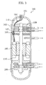
- a terminal (101) for a fluid machine (100) is typically attached to the top of a casing (102) because of ease of machining the terminal (101).
- the provision of the terminal (101) at this location requires that a through hole (107) for electric leads be formed in a partition member (106) in order to lead internal wires (104) connected with the terminal (101) to an electric motor (105).
- refrigerant discharged from a compression mechanism (108) has a temperature of approximately 90 °C, and the ambient atmosphere of the compression mechanism (108) has a relatively high temperature.
- refrigerant flowing out of an expansion mechanism (109) has a temperature of approximately 0 °C, and the ambient temperature of the expansion mechanism (109) has a relatively low temperature.
- the formation of the through hole (107) in the partition member (106) facilitates conducting heat through the compression mechanism (108) and the through hole (107) to the expansion mechanism (109). As a result, the ambient temperature of the expansion mechanism (109) increases.
- the present invention has been made in view of the foregoing, and thus, it is an object of the invention to provide a fluid machine in which a compression mechanism and an expansion mechanism are contained in the same casing and which is configured to reduce the amount of the heat input into fluid flowing from the casing into the expansion mechanism.
- a first aspect of the invention is directed to a fluid machine including: a closed casing (31); a compression mechanism (50) for compressing fluid; an expansion mechanism (60) for generating power by expansion of fluid; a drive shaft (40) allowing the compression mechanism (50) and the expansion mechanism (60) to be mechanically coupled to each other; an electric motor (45) for driving the drive shaft (40); and a terminal (90) for supplying external electric power to the electric motor (45), where an interior of the casing (31) is partitioned, by a partition member (61, 80), into a first space (38) containing the expansion mechanism (60), and a second space (39) containing the compression mechanism (50) and the electric motor (45).
- the terminal (90) is provided on the casing (31) so that a back side of the terminal (90) faces the second space (39).
- the internal space of the casing (31) is partitioned into the first space (38) and the second space (39) by the partition member (61, 80).
- the compression mechanism (50) and the electric motor (45) are placed in the second space (39). Therefore, the second space (39) contains a relatively high temperature atmosphere due to the heat of the fluid compressed by the compression mechanism (50) or the heat generated by the electric motor (45).
- the expansion mechanism (60) is placed in the first space (38). Therefore, the first space (38) contains a lower temperature atmosphere than the second space (39).
- the terminal (90) of the present invention is provided on the casing (31) so that its back side faces the second space (39).
- a through hole needs to be formed in a partition member
- the terminal (90) and the electric motor (45) can be wired together without forming such a through hole in the present invention.
- the first space (38) and the second space (39) are hermetically sealed from each other by the partition member (61, 80), this can reduce the heat transfer from the second space (39) to the first space (38) by convection.
- the electric motor (45) is disposed between the partition member (61, 80) and the compression mechanism (50), and the terminal (90) is provided on the casing (31) so that the back side of the terminal (90) faces a space between the partition member (61, 80) and the electric motor (45).
- the electric motor (45) is disposed in the second space (39) and between the partition member (61, 80) and the compression mechanism (50).
- the terminal (90) is placed so that its back side faces a space between the partition member (61, 80) and the compression mechanism (50).
- wires for the terminal (90) are disposed in the space between the partition member (61, 80) and the compression mechanism (50).
- the wires are not disposed in a space between the electric motor (45) and the compression mechanism (50). Therefore, the volume of this space can be reduced, thereby reducing the length of a portion of the drive shaft (40) between the electric motor (45) and the compression mechanism (50). This can reduce the inclination of a driving portion of the drive shaft (40) driving the compression mechanism (50) relative to a desired axis of the drive shaft (40). This reduction can prevent so-called whirling of the driving portion of the drive shaft (40).
- the compression mechanism (50) is configured to discharge the compressed fluid to the second space (39), and the casing (31) is connected with a discharge pipe (36) through which the fluid discharged from the compression mechanism (50) to the second space (39) flows out of the casing (31).
- fluid discharged from the compression mechanism (50) is sent through the second space (39) to the discharge pipe (36).
- the second space (39) is filled with high pressure, high temperature fluid.
- the formation of a through hole for wires in a partition member, for example, as illustrated in FIG. 3 further facilitates transferring heat from a second space to a first space by convection.
- the back side of the terminal (90) faces the second space (39), and therefore the terminal (90) and the electric motor (45) can be wired together without forming the through hole.
- the heat transfer from the second space (39) to the first space (38) by convection is further advantageously reduced.
- the terminal (90) is provided on the casing (31) so that the back side of the terminal (90) faces the second space (39) containing a high temperature atmosphere.
- the terminal (90) and the electric motor (45) can be wired together without forming a through hole in the partition member (61, 80). This can reduce the heat transfer from the second space (39) to the first space (38) by convection. This reduction can reduce the amount of the heat input from the compression mechanism (50) into the expansion mechanism (60) and reduce heat loss from the compression mechanism (50).
- the enthalpy of this refrigerant can be prevented from increasing, and thus, a reduction in the cooling capacity of this refrigeration system can be avoided.
- the back side of the terminal (90) faces a space between the partition member (61, 80) and the electric motor (45).
- a sufficient space for wires through which the terminal (90) and the electric motor (45) are connected to each other can be ensured.
- the distance between the electric motor (45) and the compression mechanism (60) can be reduced. This reduction can prevent whirling of the driving portion of the shaft (40) driving the compression mechanism (60) and thereby ensure the reliability of this fluid machine.
- fluid compressed by the compression mechanism (60) is discharged to the second space (39), and thus the second space (39) is filled with the high pressure fluid.
- the terminal (90) and the electric motor (45) can be wired together without forming a through hole in the partition member (61, 80). Therefore, the high pressure fluid in the second space (39) does not flow through a through hole into the first space (38).
- the amount of the heat input from the compression mechanism (50) into the expansion mechanism (60) can be advantageously reduced.
- This embodiment is directed to an air conditioner (10) including a compression/expansion unit (30) which is a fluid machine according to the present invention.
- the air conditioner (10) includes a refrigerant circuit (20).
- the refrigerant circuit (20) Connected in the refrigerant circuit (20) are the compression/expansion unit (30), an outdoor heat exchanger (23), an indoor heat exchanger (24), a first four-way selector valve (21), and a second four-way selector valve (22).
- the refrigerant circuit (20) is filled with carbon dioxide (CO 2 ) as refrigerant.
- the compression/expansion unit (30) includes a casing (31) formed in the shape of a vertically long, cylindrical, closed container.
- the casing (31) contains a compression mechanism (50), an expansion mechanism (60), and an electric motor (45). Inside the casing (31), the compression mechanism (50), the electric motor (45), and the expansion mechanism (60) are arranged in bottom-to-top order.
- the details of the compression/expansion unit (30) will be described below.
- the compression mechanism (50) is connected at its discharge side to the first port of the first four-way selector valve (21) and connected at its suction side to the fourth port of the first four-way selector valve (21).
- the expansion mechanism (60) is connected at its outflow side to the first port of the second four-way selector valve (22) and connected at its inflow side to the fourth port of the second four-way selector valve (22).
- the outdoor heat exchanger (23) is connected at one end to the second port of the second four-way selector valve (22) and connected at the other end to the third port of the first four-way selector valve (21).
- the indoor heat exchanger (24) is connected at one end to the second port of the first four-way selector valve (21) and connected at the other end to the third port of the second four-way selector valve (22).
- the first four-way selector valve (21) and the second four-way selector valve (22) are each configured to be switchable between a position in which the first and second ports are communicated with each other and the third and fourth ports are communicated with each other (the position illustrated by the solid lines in FIG. 1 ) and a position in which the first and third ports are communicated with each other and the second and fourth ports are communicated with each other (the position illustrated by the broken lines in FIG. 1 ).
- the compression/expansion unit (30) includes the above-described casing (31).
- the casing (31) is made of, for example, carbon steel.
- the casing (31) includes a cylindrical body (32) having open longitudinal ends, a top portion (33) for closing the upper end of the body (32), and a bottom portion (34) for closing the lower end of the body (32).
- the top portion (33) and the bottom portion (34) each expand outwardly and are formed in the shape of a cup.
- the body (32), the top portion (33), and the bottom portion (34) each have a thickness of, for example, approximately 8-9 mm.
- the compression mechanism (50), the electric motor (45), and the expansion mechanism (60) are arranged in bottom-to-top order. Furthermore, refrigerating machine oil (lubricating oil) is accumulated at the bottom of the casing (31).
- the internal space of the casing (31) is partitioned into upper and lower spaces by a front head (61) of the expansion mechanism (60) and a heat insulator (80).
- the front head (61) and the heat insulator (80) form a partition member for partitioning the internal space of the casing (31) into a first space (38) forming the upper space and a second space (39) forming the lower space.
- the expansion mechanism (60) is disposed in the first space (38), while the compression mechanism (50) and the electric motor (45) are disposed in the second space (49).
- the first space (38) and the second space (39) are not completely hermetically sealed from each other.
- the internal pressure of the first space (38) is approximately equal to that of the second space (39).
- the discharge pipe (36) is disposed between the electric motor (45) and the expansion mechanism (60) and communicated with the second space (39) in the casing (31). Furthermore, the discharge pipe (36) is formed in the shape of a relatively short, straight tube and placed in an approximately horizontal position.
- the electric motor (45) is disposed in a longitudinally middle part of the casing (31).
- the electric motor (45) is composed of a stator (46) and a rotor (47).
- the stator (46) includes a stator core (46a) fixed to the internal wall of the body (32) of the casing (31), and coils (46b) placed on the upper and lower sides of the stator core (46a).
- the stator (46) is fixed to the casing (31), for example, by shrink fitting.
- the rotor (47) is placed inside the stator (46).
- the rotor (47) is coaxially passed through by a main spindle (44) of a shaft (40).
- the shaft (40) forms a drive shaft.
- the shaft (40) includes two lower eccentric parts (58, 59) formed towards its lower end and two large-diameter eccentric parts (41, 42) formed towards its upper end.
- the two lower eccentric parts (58, 59) are formed with a larger diameter than the main spindle (44), in which the lower of the two lower eccentric parts (58, 59) forms a first lower eccentric part (58) and the upper thereof forms a second lower eccentric part (59).
- the first lower eccentric part (58) and the second lower eccentric part (59) have opposite directions of eccentricity with respect to the axis of the main spindle (44).
- the two large-diameter eccentric parts (41, 42) are formed with a larger diameter than the main spindle (44), in which the lower of the two large-diameter eccentric parts (41, 42) forms a first large-diameter eccentric part (41) and the upper thereof forms a second large-diameter eccentric part (42).
- the first large-diameter eccentric part (41) and the second large-diameter eccentric part (42) have the same direction of eccentricity.
- the second large-diameter eccentric part (42) has a larger outer diameter than the first large-diameter eccentric part (41). Furthermore, the degree of eccentricity of the second large-diameter eccentric part (42) with respect to the axis of the main spindle (44) is greater than that of the first large-diameter eccentric part (41).
- the shaft (40) has an oil supply passage formed therein.
- the beginning of the oil supply passage opens at the lower end of the shaft (40), and its end opens at the upper end of the shaft (40). Furthermore, an upstream portion of the oil supply passage forms a centrifugal pump.
- the oil supply passage sucks the refrigerating machine oil accumulated at the bottom of the casing (31), and the sucked refrigerating machine oil is supplied to the compression mechanism (50) and the expansion mechanism (60).
- the compression mechanism (50) forms a so-called oscillating piston rotary compressor.
- the compression mechanism (50) includes two cylinders (51, 52) and two pistons (57).
- a rear head (55), the first cylinder (51), a middle plate (56), the second cylinder (52), and a front head (54) are stacked in bottom-to-top order.
- the first and second cylinders (51, 52) contain their respective cylindrical pistons (57) disposed, one in the interior of each cylinder.
- a plate-shaped blade extends from the side surface of each piston (57) and is supported through a swing bush to the corresponding cylinder (51, 52).
- the piston (57) in the first cylinder (51) engages with the first lower eccentric part (58) of the shaft (40).
- the piston (57) in the second cylinder (52) engages with the second lower eccentric part (59) of the shaft (40).
- Each of the pistons (57, 57) is in slidable contact at its inner periphery with the outer periphery of the corresponding lower eccentric part (58, 59) and in slidable contact at its outer periphery with the inner periphery of the corresponding cylinder (51, 52).
- a compression chamber (53) is defined between the outer periphery of each of the pistons (57, 57) and the inner periphery of the corresponding cylinder (51, 52).
- the first and second cylinders (51, 52) have their respective suction ports (32) formed, one in each cylinder.
- Each suction port (32) radially passes through the corresponding cylinder (51, 52), and its distal end opens at the inner periphery of the cylinder (51, 52).
- suction pipes (132) are inserted, one into each suction port (32).
- the suction pipes (132) pass through a lower part of the body (32), and extend out of the casing (31).
- the front head (54) and rear head (55) have their respective discharge ports formed, one in each head.
- the discharge port in the front head (54) brings the compression chamber (53) in the second cylinder (52) into communication with the second space (39).
- the discharge port in the rear head (55) brings the compression chamber (53) in the first cylinder (51) into communication with the second space (39).
- each discharge port is provided at its distal end with a discharge valve composed of a lead valve, and configured to be opened and closed by the discharge valve. In FIG. 2 , the discharge ports and discharge valves are not illustrated.
- the gas refrigerant discharged from the compression mechanism (50) into the second space (39) is sent through the discharge pipe (36) out of the compression/expansion unit (30).
- refrigerating machine oil is supplied through the oil supply passage to the compression mechanism (50).
- passages branched from the oil supply passage open at the outer peripheries of the lower eccentric parts (58, 59) and the outer periphery of the main spindle (44).
- the refrigerating machine oil is supplied through these passages to the sliding surfaces between each lower eccentric part (58, 59) and the corresponding piston (57, 57) and the sliding surfaces between the main spindle (44) and each of the front head (54) and the rear head (55).
- the expansion mechanism (60) is comprised of a so-called oscillating piston fluid machine.
- the expansion mechanism (60) includes two cylinders (71, 81) and two pistons (75, 85) which form two cylinder/piston pairs.
- the expansion mechanism (60) further includes the front head (61), a middle plate (63), and a rear head (62).
- the front head (61), the first cylinder (71), the middle plate (63), the second cylinder (81), and the rear head (62) are stacked in bottom-to-top order.
- the first cylinder (71) is closed at the lower end surface by the front head (61) and closed at the upper end surface by the middle plate (63).
- the second cylinder (81) is closed at the lower end surface by the middle plate (63) and closed at the upper end surface by the rear head (62). Furthermore, an inner diameter of the second cylinder (81) is larger than that of the first cylinder (71).
- the heat insulator (80) is disposed under the front head (61).
- the heat insulator (80) is formed in the shape of a flat disc, and fitted into the body (32) of the casing (31).
- the heat insulator (80) shields the lower surface of the front head (61) from the second space (39).
- a material of low heat conductivity such as PI (polyimide) and PPS (polyphenylene sulfide), is used as a material of the heat insulator (80).
- the shaft (40) passes through the front head (61), the first cylinder (71), the middle plate (63), the second cylinder (81), the rear head (62), and the heat insulator (80) which are stacked. Furthermore, the first large-diameter eccentric part (41) of the shaft (40) is located inside the first cylinder (71), and the second large-diameter eccentric part (42) thereof is located inside the second cylinder (81).
- the first and second cylinders (71, 81) contain their respective cylindrical pistons (75, 85) disposed, one in the interior of each cylinder.
- a plate-shaped blade extends from the side surface of each piston (75, 85) and is supported through a swing bush to the corresponding cylinder (71, 81).
- the outer diameters of the first piston (75) and the second piston (85) are equal to each other.
- the inner diameter of the first piston (75) is approximately equal to the outer diameter of the first large-diameter eccentric part (41), and the inner diameter of the second piston (85) is approximately equal to the outer diameter of the second large-diameter eccentric part (42).
- the first piston (75) and the second piston (85) are engaged with the first large-diameter eccentric part (41) and the second large-diameter eccentric part (42), respectively.
- the first piston (75) is in slidable contact at the outer periphery with the inner periphery of the first cylinder (71), is in slidable contact at one end surface thereof with the front head (61), and is in slidable contact at the other end surface with the middle plate (63).
- first cylinder (71) its inner periphery and the outer periphery of the first piston (75) define a first fluid chamber (72).
- the second piston (85) is in slidable contact at the outer periphery with the inner periphery of the second cylinder (81), is in slidable contact at one end surface thereof with the rear head (62), and is in slidable contact at the other end surface with the middle plate (63).
- the second cylinder (81) its inner periphery and the outer periphery of the second piston (85) define a second fluid chamber (82).
- the first cylinder (71) has an inlet port (34) formed therein.
- the inlet port (34) can be communicated with the first fluid chamber (72).
- An inlet pipe (134) made of copper is inserted into the inlet port (34).
- the inlet pipe (134) passes through an upper part of the body (32) and extends out of the casing (31).
- the second cylinder (81) has an outlet port (35) formed therein.
- the outlet port (35) can be communicated with the second fluid chamber (82).
- An outlet pipe (135) made of copper is inserted into the outlet port (35).
- the outlet pipe (135) passes through the upper part of the body (32) and extends out of the casing (31).
- the middle plate (63) has a communicating passage (64) formed therein.
- the communicating passage (64) extends obliquely with respect to the thickness direction of the middle plate (63), and allows communication between the first fluid chamber (72) and the second fluid chamber (82).
- the compression/expansion unit (30) includes a terminal (90) for supplying external electric power to the electric motor (45).
- the terminal (90) is provided in the lateral side of the body (32) of the casing (31) and between the heat insulator (80) and the electric motor (45).
- the terminal (90) includes a terminal body (91) and a plurality of terminal pins (92).
- the terminal body (91) is formed in the shape of a flat lid.
- a fitting hole (32a) into which the terminal body (91) is fitted is formed in the body (32) of the casing (31).
- the terminal body (91) is welded to the casing (31) while being fitted into the fitting hole (32a).
- Three terminal pins (92) are maintained while passing through the terminal body (91).
- the terminal pins (92) are fixed through an insulating material, such as glass, to the terminal body (91).
- One ends of the terminal pins (92) project outward of the terminal body (91).
- the one ends of the terminal pins (92) are electrically connected through unshown external wires to an external power source.
- the other ends of the terminal pins (92) project backward of the terminal body (91), i.e., toward the second space (39).
- the distance between the heat insulator (80) and the electric motor (45) is greater than that between the electric motor (45) and the compression mechanism (50).
- a wiring space for a plurality of internal wires (93) is ensured between the heat insulator (80) and the electric motor (45). Specifically, one ends of the internal wires (93) are connected, one to each terminal pin (92). The other ends of the internal wires are connected to the upper coil (46b) of the electric motor (45).
- the unshown external power source is electrically connected to the electric motor (45) through the external wires, the terminal (90), and the internal wires (93).
- the first four-way selector valve (21) and the second four-way selector valve (22) are switched to the positions illustrated by the broken lines in FIG. 1 .
- the electric motor (45) of the compression/expansion unit (30) is energized, refrigerant circulates through the refrigerant circuit (20) so that the refrigerant circuit (20) operates in a vapor compression refrigeration cycle.
- the electric motor (45) drives the shaft (40) to rotate. Consequently, in the compression mechanism (50), the pistons (57) rotate eccentrically relative to the corresponding cylinders (51, 52), and refrigerant is compressed in the compression chambers (53).
- the fluid compressed in the compression chambers (53) is discharged through the discharge ports to the second space (39).
- the discharged refrigerant has a pressure which is equal to or higher than its critical pressure, and a relatively high temperature (e.g., approximately 90-100 °C).
- the refrigerant discharged to the second space (39) flows upwardly and then flows out of the discharge pipe (36).
- the refrigerant which has flowed out of the discharge pipe (36) is sent to the outdoor heat exchanger (23) to radiate heat to the outdoor air.
- the high-pressure refrigerant from which heat has been radiated by the outdoor heat exchanger (23) flows through the inlet pipe (134) into the expansion mechanism (60).
- the temperature of this refrigerant is, for example, approximately 20-30 °C.
- the refrigerant initially expands in the first fluid chamber (72).
- the expanded refrigerant flows through the communicating passage (64) into the second fluid chamber (82).
- the refrigerant having further expanded in the second fluid chamber (82) passes through the outlet pipe (135) and flows out of the expansion mechanism (60).
- the temperature of this refrigerant is, for example, approximately -10-0 °C.
- the expansion mechanism (60) the expanding power of the refrigerant in the first fluid chamber (72) and the second fluid chamber (82) is recovered, as the torque of the shaft (40), through the pistons (75, 85).
- the refrigerant exiting the expansion mechanism (60) is sent to the indoor heat exchanger (24).
- the refrigerant absorbs heat from the outdoor air to evaporate, thereby cooling room air.
- the low-pressure gas refrigerant exiting the indoor heat exchanger (24) is split into the two suction pipes (132) and is then sucked into the compression mechanism (50).
- the first four-way selector valve (21) and the second four-way selector valve (22) are switched to the positions illustrated by the solid lines in FIG. 1 .
- the compression/expansion unit (30) operates as in the cooling operation. Consequently, the refrigerant circuit (20) operates in a refrigeration cycle where heat is radiated from refrigerant by the indoor heat exchanger (24) and the refrigerant is evaporated by the outdoor heat exchanger (23).
- the compression/expansion unit (30) In the cooling and heating operations as described above, in the compression/expansion unit (30), a temperature difference exists between the ambient atmosphere of the expansion mechanism (60) and the ambient atmosphere of the compression mechanism (50). Specifically, the atmosphere of the second space (39) has a higher temperature than that of the first space (38).
- the heat insulator (80) is disposed between the first space (38) and the second space (39). This reduces the heat transfer from the second space (39) to the first space (38) by convection.
- the terminal (90) of this embodiment is provided in the body (32) of the casing (31) so that the back side of the terminal (90) faces the second space (39).
- This arrangement prevents the heat insulator (80) and the front head (61) from being interposed between the terminal (90) and the electric motor (45).
- a through hole (107) needs to be formed in a partition member (106) in order to connect a terminal (101) and an electric motor (105) through internal wires (104).
- a through hole is not required.
- the terminal (90) is provided on the casing (31) so that the back side of the terminal (90) faces the second space (39) filled with high-temperature refrigerant.
- the terminal (90) and the electric motor (45) can be wired together without forming a through hole in the partition member (61, 80). This can reduce the heat transfer from the second space (39) to the first space (38) by convection. This reduction can reduce the amount of the heat input from the compression mechanism (50) into the expansion mechanism (60) and reduce heat loss from the compression mechanism (50).
- the enthalpy of refrigerant sent from the expansion mechanism (60) to the indoor heat exchanger (24) can be prevented from increasing, for example, in cooling operation. This prevention can avoid a reduction in the cooling capacity of the air conditioner (10).
- a process for forming a through hole in the front head (61) and the heat insulator (80) is not required. This can simplify the machine structure.
- the back side of the terminal (90) faces a space between the partition member (61, 80) and the electric motor (45), this can ensure a sufficient space for wires through which the terminal (90) and the electric motor (45) are connected to each other.
- the distance between the electric motor (45) and the compression mechanism (60) can be reduced. This reduction can reliably prevent the axis of the shaft (40) from being inclined in the compression mechanism (60). This prevention can prevent whirling of the shaft (40) in the compression mechanism (60) and thereby ensure the reliability of this compression/expansion unit (30).
- the fluid machine of the above embodiment may be configured as follows.
- the first space (38) and the second space (39) may be completely hermetically sealed from each other.
- a sealer for hermetically isolating the first space (38) and the second space (39) from each other may be used to completely prevent high-pressure refrigerant in the second space (39) from entering into the first space (38).
- fluid expanded by the expansion mechanism (60) may be allowed to flow out into the first space (38).
- the first space (38) may be filled with the low-pressure refrigerant.
- the inlet pipe (135) is connected to the casing (31) to allow the low-pressure refrigerant having flowed out into the first space (3 8) to flow out of the casing (31).
- the front head (61) and the heat insulator (80) are used as a partition member.
- only one of the front head (61) and the heat insulator (80) may be used as a partition member.
- any partition member other than these may be used.
- the expansion mechanism (60) is comprised of an oscillating piston rotary fluid machine
- the type of a fluid machine forming the expansion mechanism (60) is not limited thereto.
- the expansion mechanism (60) may be comprised of a rolling piston rotary fluid machine.
- the expansion mechanism (60) may be comprised of a scroll fluid machine.
- the air conditioner (10) of the above embodiment carbon dioxide (CO 2 ) is used as refrigerant
- a material used as refrigerant to fill the refrigerant circuit (20) is not limited thereto.
- the refrigerant circuit (20) may be filled with so-called fluorocarbon refrigerant, such as R410A or R407C.
- the pressure of the high-pressure refrigerant circulating within a refrigeration cycle is set higher than the critical pressure thereof, it may be set equal to or lower than the critical pressure.
- the present invention is useful for a fluid machine in which a compression mechanism for compressing fluid and an expansion mechanism are contained in a single casing.
Landscapes
- Engineering & Computer Science (AREA)
- Mechanical Engineering (AREA)
- General Engineering & Computer Science (AREA)
- Applications Or Details Of Rotary Compressors (AREA)
- Compressor (AREA)
Abstract
Description
- The present invention relates to fluid machines in which a compression mechanism and an expansion mechanism are contained in a single casing.
- Fluid machines have been known in which a compression mechanism and an expansion mechanism are mechanically coupled to each other by a drive shaft. In such a fluid machine, the expansion mechanism generates power by expanding fluid introduced thereinto. The power generated by the expansion mechanism, together with power generated by an electric motor, is transmitted to the compression mechanism by the drive shaft. Then, the compression mechanism is driven by the power transmitted from the expansion mechanism and the electric motor to suck the fluid and compress it.
-
PATENT DOCUMENT 1 describes a fluid machine of this type. In such a fluid machine, an expansion mechanism, an electric motor, a compression mechanism, and a drive shaft are contained in a vertically long, cylindrical casing. The internal space of the casing is partitioned into a first space and a second space by a partition member. The expansion mechanism is placed in the first space. The electric motor and the compression mechanism are placed in the second space. The expansion mechanism and the compression mechanism are both comprised of rotary fluid machines. - The fluid machine of
PATENT DOCUMENT 1 is disposed in an air conditioner operating in a refrigeration cycle. Low-pressure refrigerant having a temperature of approximately 5 °C is sucked from an evaporator into the compression mechanism. The low-pressure refrigerant is compressed, and the resultant high-pressure refrigerant having a temperature of approximately 90 °C is discharged from the compression mechanism. The high-pressure refrigerant discharged from the compression mechanism flows through the second space of the casing, and is discharged through a discharge pipe to the outside of the casing. On the other hand, high-pressure refrigerant having a temperature of approximately 30 °C is introduced from a radiator into the expansion mechanism. The high-pressure refrigerant is expanded, and the resultant low-pressure refrigerant having a temperature of approximately 0 °C is sent from the expansion mechanism to the evaporator. - Furthermore, in such a fluid machine, a terminal is typically used to supply external electric power to an electric motor. For example, this terminal includes a terminal body which is inserted through an opening formed in the top of a casing and which is welded to the casing, and a plurality of terminal pins passing through the terminal body. Parts of the terminal pins located at the front side of the terminal body are connected to a predetermined power source by external wires. Parts of the terminal pins located at the back side of the terminal body are connected to the electric motor by internal wires. Electric power from an external power source is supplied through the external wires, the terminal, and the internal wires to the electric motor. In this way, the electric motor is energized to drive a corresponding drive shaft.
- PATENT DOCUMENT 1: Japanese Patent Publication No.
2003-172244 - Here, when the terminal is employed to such a fluid machine as described in
PATENT DOCUMENT 1, the following problems are caused. - For example, as illustrated in
FIG. 3 , a terminal (101) for a fluid machine (100) is typically attached to the top of a casing (102) because of ease of machining the terminal (101). However, the provision of the terminal (101) at this location requires that a through hole (107) for electric leads be formed in a partition member (106) in order to lead internal wires (104) connected with the terminal (101) to an electric motor (105). Here, as described above, refrigerant discharged from a compression mechanism (108) has a temperature of approximately 90 °C, and the ambient atmosphere of the compression mechanism (108) has a relatively high temperature. On the other hand, refrigerant flowing out of an expansion mechanism (109) has a temperature of approximately 0 °C, and the ambient temperature of the expansion mechanism (109) has a relatively low temperature. In view of the above, the formation of the through hole (107) in the partition member (106) facilitates conducting heat through the compression mechanism (108) and the through hole (107) to the expansion mechanism (109). As a result, the ambient temperature of the expansion mechanism (109) increases. - When the heat input from the compression mechanism (108) into the expansion mechanism (109) is promoted in this manner, heat loss of the refrigerant discharged from the compression mechanism (108) is caused. Furthermore, for example, due to the heat input into the expansion mechanism (109), the enthalpy of refrigerant sent from the expansion mechanism (109) to an evaporator increases, resulting in a reduction in the cooling capacity of a corresponding refrigeration system. In particular, when the refrigerant is discharged from the compression mechanism (108) to a surrounding space (110) of the compression mechanism (108) as in
PATENT DOCUMENT 1, the heat of the discharged refrigerant in this space (110) tends to be transferred through the through hole (107) to a surrounding space (111) of the expansion mechanism (109) by convection. In view of the above, in a fluid machine having this configuration, the above-mentioned problems become serious. - The present invention has been made in view of the foregoing, and thus, it is an object of the invention to provide a fluid machine in which a compression mechanism and an expansion mechanism are contained in the same casing and which is configured to reduce the amount of the heat input into fluid flowing from the casing into the expansion mechanism.
- A first aspect of the invention is directed to a fluid machine including: a closed casing (31); a compression mechanism (50) for compressing fluid; an expansion mechanism (60) for generating power by expansion of fluid; a drive shaft (40) allowing the compression mechanism (50) and the expansion mechanism (60) to be mechanically coupled to each other; an electric motor (45) for driving the drive shaft (40); and a terminal (90) for supplying external electric power to the electric motor (45), where an interior of the casing (31) is partitioned, by a partition member (61, 80), into a first space (38) containing the expansion mechanism (60), and a second space (39) containing the compression mechanism (50) and the electric motor (45). In this fluid machine, the terminal (90) is provided on the casing (31) so that a back side of the terminal (90) faces the second space (39).
- In the first aspect of the invention, the internal space of the casing (31) is partitioned into the first space (38) and the second space (39) by the partition member (61, 80). The compression mechanism (50) and the electric motor (45) are placed in the second space (39). Therefore, the second space (39) contains a relatively high temperature atmosphere due to the heat of the fluid compressed by the compression mechanism (50) or the heat generated by the electric motor (45). On the other hand, the expansion mechanism (60) is placed in the first space (38). Therefore, the first space (38) contains a lower temperature atmosphere than the second space (39).
- Here, the terminal (90) of the present invention is provided on the casing (31) so that its back side faces the second space (39). For this reason, although, for example, for the terminal illustrated in
FIG. 3 , a through hole needs to be formed in a partition member, the terminal (90) and the electric motor (45) can be wired together without forming such a through hole in the present invention. In view of the above, since the first space (38) and the second space (39) are hermetically sealed from each other by the partition member (61, 80), this can reduce the heat transfer from the second space (39) to the first space (38) by convection. - According to a second aspect of the invention, in the fluid machine of the first aspect of the invention, the electric motor (45) is disposed between the partition member (61, 80) and the compression mechanism (50), and the terminal (90) is provided on the casing (31) so that the back side of the terminal (90) faces a space between the partition member (61, 80) and the electric motor (45).
- In the second aspect of the invention, the electric motor (45) is disposed in the second space (39) and between the partition member (61, 80) and the compression mechanism (50). Here, the terminal (90) is placed so that its back side faces a space between the partition member (61, 80) and the compression mechanism (50). Specifically, wires for the terminal (90) are disposed in the space between the partition member (61, 80) and the compression mechanism (50). For this reason, in the present invention, the wires are not disposed in a space between the electric motor (45) and the compression mechanism (50). Therefore, the volume of this space can be reduced, thereby reducing the length of a portion of the drive shaft (40) between the electric motor (45) and the compression mechanism (50). This can reduce the inclination of a driving portion of the drive shaft (40) driving the compression mechanism (50) relative to a desired axis of the drive shaft (40). This reduction can prevent so-called whirling of the driving portion of the drive shaft (40).
- According to a third aspect of the invention, in the fluid machine of the first or second aspect of the invention, the compression mechanism (50) is configured to discharge the compressed fluid to the second space (39), and the casing (31) is connected with a discharge pipe (36) through which the fluid discharged from the compression mechanism (50) to the second space (39) flows out of the casing (31).
- In the third aspect of the invention, fluid discharged from the compression mechanism (50) is sent through the second space (39) to the discharge pipe (36). In other words, the second space (39) is filled with high pressure, high temperature fluid. In this configuration, the formation of a through hole for wires in a partition member, for example, as illustrated in
FIG. 3 , further facilitates transferring heat from a second space to a first space by convection. On the other hand, in the present invention, the back side of the terminal (90) faces the second space (39), and therefore the terminal (90) and the electric motor (45) can be wired together without forming the through hole. In view of the above, in the present invention, the heat transfer from the second space (39) to the first space (38) by convection is further advantageously reduced. - In the present invention, the terminal (90) is provided on the casing (31) so that the back side of the terminal (90) faces the second space (39) containing a high temperature atmosphere. Thus, according to the present invention, the terminal (90) and the electric motor (45) can be wired together without forming a through hole in the partition member (61, 80). This can reduce the heat transfer from the second space (39) to the first space (38) by convection. This reduction can reduce the amount of the heat input from the compression mechanism (50) into the expansion mechanism (60) and reduce heat loss from the compression mechanism (50). Furthermore, for example, in a refrigeration system in which refrigerant exiting the expansion mechanism (60) is sent to an evaporator, the enthalpy of this refrigerant can be prevented from increasing, and thus, a reduction in the cooling capacity of this refrigeration system can be avoided.
- In particular, in the second aspect of the invention, the back side of the terminal (90) faces a space between the partition member (61, 80) and the electric motor (45). Thus, according to the present invention, a sufficient space for wires through which the terminal (90) and the electric motor (45) are connected to each other can be ensured. On the other hand, the distance between the electric motor (45) and the compression mechanism (60) can be reduced. This reduction can prevent whirling of the driving portion of the shaft (40) driving the compression mechanism (60) and thereby ensure the reliability of this fluid machine.
- Furthermore, in the third aspect of the invention, fluid compressed by the compression mechanism (60) is discharged to the second space (39), and thus the second space (39) is filled with the high pressure fluid. Here, in the present invention, the terminal (90) and the electric motor (45) can be wired together without forming a through hole in the partition member (61, 80). Therefore, the high pressure fluid in the second space (39) does not flow through a through hole into the first space (38). In view of the above, according to the present invention, the amount of the heat input from the compression mechanism (50) into the expansion mechanism (60) can be advantageously reduced.
-
- [
FIG. 1] FIG. 1 is a refrigerant circuit diagram illustrating the configuration of a refrigerant circuit according to an embodiment. - [
FIG. 2] FIG. 2 is a longitudinal cross-sectional view of a compression/expansion unit according to the embodiment. - [
FIG. 3] FIG. 3 is a longitudinal cross-sectional view of a compression/expansion unit used to explain the problem to be solved by the present invention. -
- 30
- COMPRESSION/EXPANSION UNIT
- 31
- CASING
- 36
- DISCHARGE PIPE
- 38
- FIRST SPACE
- 39
- SECOND SPACE
- 40
- SHAFT (DRIVE SHAFT)
- 45
- ELECTRIC MOTOR
- 50
- COMPRESSION MECHANISM
- 60
- EXPANSION MECHANISM
- 90
- TERMINAL
- An embodiment of the present invention will be described below in detail with reference to the drawings.
- This embodiment is directed to an air conditioner (10) including a compression/expansion unit (30) which is a fluid machine according to the present invention.
- As illustrated in
FIG. 1 , the air conditioner (10) according to this embodiment includes a refrigerant circuit (20). Connected in the refrigerant circuit (20) are the compression/expansion unit (30), an outdoor heat exchanger (23), an indoor heat exchanger (24), a first four-way selector valve (21), and a second four-way selector valve (22). Furthermore, the refrigerant circuit (20) is filled with carbon dioxide (CO2) as refrigerant. - The compression/expansion unit (30) includes a casing (31) formed in the shape of a vertically long, cylindrical, closed container. The casing (31) contains a compression mechanism (50), an expansion mechanism (60), and an electric motor (45). Inside the casing (31), the compression mechanism (50), the electric motor (45), and the expansion mechanism (60) are arranged in bottom-to-top order. The details of the compression/expansion unit (30) will be described below.
- In the refrigerant circuit (20), the compression mechanism (50) is connected at its discharge side to the first port of the first four-way selector valve (21) and connected at its suction side to the fourth port of the first four-way selector valve (21). On the other hand, the expansion mechanism (60) is connected at its outflow side to the first port of the second four-way selector valve (22) and connected at its inflow side to the fourth port of the second four-way selector valve (22).
- Furthermore, in the refrigerant circuit (20), the outdoor heat exchanger (23) is connected at one end to the second port of the second four-way selector valve (22) and connected at the other end to the third port of the first four-way selector valve (21). On the other hand, the indoor heat exchanger (24) is connected at one end to the second port of the first four-way selector valve (21) and connected at the other end to the third port of the second four-way selector valve (22).
- The first four-way selector valve (21) and the second four-way selector valve (22) are each configured to be switchable between a position in which the first and second ports are communicated with each other and the third and fourth ports are communicated with each other (the position illustrated by the solid lines in
FIG. 1 ) and a position in which the first and third ports are communicated with each other and the second and fourth ports are communicated with each other (the position illustrated by the broken lines inFIG. 1 ). - As illustrated in
FIG. 2 , the compression/expansion unit (30) includes the above-described casing (31). The casing (31) is made of, for example, carbon steel. The casing (31) includes a cylindrical body (32) having open longitudinal ends, a top portion (33) for closing the upper end of the body (32), and a bottom portion (34) for closing the lower end of the body (32). The top portion (33) and the bottom portion (34) each expand outwardly and are formed in the shape of a cup. The body (32), the top portion (33), and the bottom portion (34) each have a thickness of, for example, approximately 8-9 mm. - Inside the casing (31), the compression mechanism (50), the electric motor (45), and the expansion mechanism (60) are arranged in bottom-to-top order. Furthermore, refrigerating machine oil (lubricating oil) is accumulated at the bottom of the casing (31).
- The internal space of the casing (31) is partitioned into upper and lower spaces by a front head (61) of the expansion mechanism (60) and a heat insulator (80). In other words, the front head (61) and the heat insulator (80) form a partition member for partitioning the internal space of the casing (31) into a first space (38) forming the upper space and a second space (39) forming the lower space. The expansion mechanism (60) is disposed in the first space (38), while the compression mechanism (50) and the electric motor (45) are disposed in the second space (49). The first space (38) and the second space (39) are not completely hermetically sealed from each other. The internal pressure of the first space (38) is approximately equal to that of the second space (39).
- Attached to the casing (31) is the discharge pipe (36). The discharge pipe (36) is disposed between the electric motor (45) and the expansion mechanism (60) and communicated with the second space (39) in the casing (31). Furthermore, the discharge pipe (36) is formed in the shape of a relatively short, straight tube and placed in an approximately horizontal position.
- The electric motor (45) is disposed in a longitudinally middle part of the casing (31). The electric motor (45) is composed of a stator (46) and a rotor (47). The stator (46) includes a stator core (46a) fixed to the internal wall of the body (32) of the casing (31), and coils (46b) placed on the upper and lower sides of the stator core (46a). The stator (46) is fixed to the casing (31), for example, by shrink fitting. The rotor (47) is placed inside the stator (46). The rotor (47) is coaxially passed through by a main spindle (44) of a shaft (40).
- The shaft (40) forms a drive shaft. The shaft (40) includes two lower eccentric parts (58, 59) formed towards its lower end and two large-diameter eccentric parts (41, 42) formed towards its upper end.
- The two lower eccentric parts (58, 59) are formed with a larger diameter than the main spindle (44), in which the lower of the two lower eccentric parts (58, 59) forms a first lower eccentric part (58) and the upper thereof forms a second lower eccentric part (59). The first lower eccentric part (58) and the second lower eccentric part (59) have opposite directions of eccentricity with respect to the axis of the main spindle (44).
- The two large-diameter eccentric parts (41, 42) are formed with a larger diameter than the main spindle (44), in which the lower of the two large-diameter eccentric parts (41, 42) forms a first large-diameter eccentric part (41) and the upper thereof forms a second large-diameter eccentric part (42). The first large-diameter eccentric part (41) and the second large-diameter eccentric part (42) have the same direction of eccentricity. The second large-diameter eccentric part (42) has a larger outer diameter than the first large-diameter eccentric part (41). Furthermore, the degree of eccentricity of the second large-diameter eccentric part (42) with respect to the axis of the main spindle (44) is greater than that of the first large-diameter eccentric part (41).
- Although not illustrated, the shaft (40) has an oil supply passage formed therein. The beginning of the oil supply passage opens at the lower end of the shaft (40), and its end opens at the upper end of the shaft (40). Furthermore, an upstream portion of the oil supply passage forms a centrifugal pump. The oil supply passage sucks the refrigerating machine oil accumulated at the bottom of the casing (31), and the sucked refrigerating machine oil is supplied to the compression mechanism (50) and the expansion mechanism (60).
- The compression mechanism (50) forms a so-called oscillating piston rotary compressor. The compression mechanism (50) includes two cylinders (51, 52) and two pistons (57). In the compression mechanism (50), a rear head (55), the first cylinder (51), a middle plate (56), the second cylinder (52), and a front head (54) are stacked in bottom-to-top order.
- The first and second cylinders (51, 52) contain their respective cylindrical pistons (57) disposed, one in the interior of each cylinder. Although not illustrated, a plate-shaped blade extends from the side surface of each piston (57) and is supported through a swing bush to the corresponding cylinder (51, 52). The piston (57) in the first cylinder (51) engages with the first lower eccentric part (58) of the shaft (40). On the other hand, the piston (57) in the second cylinder (52) engages with the second lower eccentric part (59) of the shaft (40). Each of the pistons (57, 57) is in slidable contact at its inner periphery with the outer periphery of the corresponding lower eccentric part (58, 59) and in slidable contact at its outer periphery with the inner periphery of the corresponding cylinder (51, 52). Thus, a compression chamber (53) is defined between the outer periphery of each of the pistons (57, 57) and the inner periphery of the corresponding cylinder (51, 52).
- The first and second cylinders (51, 52) have their respective suction ports (32) formed, one in each cylinder. Each suction port (32) radially passes through the corresponding cylinder (51, 52), and its distal end opens at the inner periphery of the cylinder (51, 52). Furthermore, suction pipes (132) are inserted, one into each suction port (32). The suction pipes (132) pass through a lower part of the body (32), and extend out of the casing (31).
- The front head (54) and rear head (55) have their respective discharge ports formed, one in each head. The discharge port in the front head (54) brings the compression chamber (53) in the second cylinder (52) into communication with the second space (39). The discharge port in the rear head (55) brings the compression chamber (53) in the first cylinder (51) into communication with the second space (39). Furthermore, each discharge port is provided at its distal end with a discharge valve composed of a lead valve, and configured to be opened and closed by the discharge valve. In
FIG. 2 , the discharge ports and discharge valves are not illustrated. The gas refrigerant discharged from the compression mechanism (50) into the second space (39) is sent through the discharge pipe (36) out of the compression/expansion unit (30). - As described above, refrigerating machine oil is supplied through the oil supply passage to the compression mechanism (50). Although not illustrated, passages branched from the oil supply passage open at the outer peripheries of the lower eccentric parts (58, 59) and the outer periphery of the main spindle (44). The refrigerating machine oil is supplied through these passages to the sliding surfaces between each lower eccentric part (58, 59) and the corresponding piston (57, 57) and the sliding surfaces between the main spindle (44) and each of the front head (54) and the rear head (55).
- The expansion mechanism (60) is comprised of a so-called oscillating piston fluid machine. The expansion mechanism (60) includes two cylinders (71, 81) and two pistons (75, 85) which form two cylinder/piston pairs. The expansion mechanism (60) further includes the front head (61), a middle plate (63), and a rear head (62).
- In the expansion mechanism (60), the front head (61), the first cylinder (71), the middle plate (63), the second cylinder (81), and the rear head (62) are stacked in bottom-to-top order. In this state, the first cylinder (71) is closed at the lower end surface by the front head (61) and closed at the upper end surface by the middle plate (63). On the other hand, the second cylinder (81) is closed at the lower end surface by the middle plate (63) and closed at the upper end surface by the rear head (62). Furthermore, an inner diameter of the second cylinder (81) is larger than that of the first cylinder (71).
- The heat insulator (80) is disposed under the front head (61). The heat insulator (80) is formed in the shape of a flat disc, and fitted into the body (32) of the casing (31). The heat insulator (80) shields the lower surface of the front head (61) from the second space (39).
- A material of low heat conductivity, such as PI (polyimide) and PPS (polyphenylene sulfide), is used as a material of the heat insulator (80).
- The shaft (40) passes through the front head (61), the first cylinder (71), the middle plate (63), the second cylinder (81), the rear head (62), and the heat insulator (80) which are stacked. Furthermore, the first large-diameter eccentric part (41) of the shaft (40) is located inside the first cylinder (71), and the second large-diameter eccentric part (42) thereof is located inside the second cylinder (81).
- The first and second cylinders (71, 81) contain their respective cylindrical pistons (75, 85) disposed, one in the interior of each cylinder. Although not illustrated, a plate-shaped blade extends from the side surface of each piston (75, 85) and is supported through a swing bush to the corresponding cylinder (71, 81). The outer diameters of the first piston (75) and the second piston (85) are equal to each other. The inner diameter of the first piston (75) is approximately equal to the outer diameter of the first large-diameter eccentric part (41), and the inner diameter of the second piston (85) is approximately equal to the outer diameter of the second large-diameter eccentric part (42). The first piston (75) and the second piston (85) are engaged with the first large-diameter eccentric part (41) and the second large-diameter eccentric part (42), respectively.
- The first piston (75) is in slidable contact at the outer periphery with the inner periphery of the first cylinder (71), is in slidable contact at one end surface thereof with the front head (61), and is in slidable contact at the other end surface with the middle plate (63). In the first cylinder (71), its inner periphery and the outer periphery of the first piston (75) define a first fluid chamber (72). On the other hand, the second piston (85) is in slidable contact at the outer periphery with the inner periphery of the second cylinder (81), is in slidable contact at one end surface thereof with the rear head (62), and is in slidable contact at the other end surface with the middle plate (63). In the second cylinder (81), its inner periphery and the outer periphery of the second piston (85) define a second fluid chamber (82).
- The first cylinder (71) has an inlet port (34) formed therein. The inlet port (34) can be communicated with the first fluid chamber (72). An inlet pipe (134) made of copper is inserted into the inlet port (34). The inlet pipe (134) passes through an upper part of the body (32) and extends out of the casing (31). On the other hand, the second cylinder (81) has an outlet port (35) formed therein. The outlet port (35) can be communicated with the second fluid chamber (82). An outlet pipe (135) made of copper is inserted into the outlet port (35). The outlet pipe (135) passes through the upper part of the body (32) and extends out of the casing (31).
- The middle plate (63) has a communicating passage (64) formed therein. The communicating passage (64) extends obliquely with respect to the thickness direction of the middle plate (63), and allows communication between the first fluid chamber (72) and the second fluid chamber (82).
- The compression/expansion unit (30) includes a terminal (90) for supplying external electric power to the electric motor (45). The terminal (90) is provided in the lateral side of the body (32) of the casing (31) and between the heat insulator (80) and the electric motor (45). The terminal (90) includes a terminal body (91) and a plurality of terminal pins (92). The terminal body (91) is formed in the shape of a flat lid. A fitting hole (32a) into which the terminal body (91) is fitted is formed in the body (32) of the casing (31). The terminal body (91) is welded to the casing (31) while being fitted into the fitting hole (32a).
- Three terminal pins (92) are maintained while passing through the terminal body (91). The terminal pins (92) are fixed through an insulating material, such as glass, to the terminal body (91). One ends of the terminal pins (92) project outward of the terminal body (91). The one ends of the terminal pins (92) are electrically connected through unshown external wires to an external power source. The other ends of the terminal pins (92) project backward of the terminal body (91), i.e., toward the second space (39).
- In the compression/expansion unit (30), the distance between the heat insulator (80) and the electric motor (45) is greater than that between the electric motor (45) and the compression mechanism (50). A wiring space for a plurality of internal wires (93) is ensured between the heat insulator (80) and the electric motor (45). Specifically, one ends of the internal wires (93) are connected, one to each terminal pin (92). The other ends of the internal wires are connected to the upper coil (46b) of the electric motor (45). In the above-described manner, the unshown external power source is electrically connected to the electric motor (45) through the external wires, the terminal (90), and the internal wires (93).
- Actions of the air conditioner (10) will be described below. Here, cooling operation of the air conditioner (10) will be described in detail as a typical example.
- In cooling operation, the first four-way selector valve (21) and the second four-way selector valve (22) are switched to the positions illustrated by the broken lines in
FIG. 1 . When in this state the electric motor (45) of the compression/expansion unit (30) is energized, refrigerant circulates through the refrigerant circuit (20) so that the refrigerant circuit (20) operates in a vapor compression refrigeration cycle. - In the compression/expansion unit (30) illustrated in
FIG. 2 , the electric motor (45) drives the shaft (40) to rotate. Consequently, in the compression mechanism (50), the pistons (57) rotate eccentrically relative to the corresponding cylinders (51, 52), and refrigerant is compressed in the compression chambers (53). The fluid compressed in the compression chambers (53) is discharged through the discharge ports to the second space (39). The discharged refrigerant has a pressure which is equal to or higher than its critical pressure, and a relatively high temperature (e.g., approximately 90-100 °C). - The refrigerant discharged to the second space (39) flows upwardly and then flows out of the discharge pipe (36). The refrigerant which has flowed out of the discharge pipe (36) is sent to the outdoor heat exchanger (23) to radiate heat to the outdoor air. The high-pressure refrigerant from which heat has been radiated by the outdoor heat exchanger (23) flows through the inlet pipe (134) into the expansion mechanism (60). The temperature of this refrigerant is, for example, approximately 20-30 °C.
- In the expansion mechanism (60), the refrigerant initially expands in the first fluid chamber (72). The expanded refrigerant flows through the communicating passage (64) into the second fluid chamber (82). The refrigerant having further expanded in the second fluid chamber (82) passes through the outlet pipe (135) and flows out of the expansion mechanism (60). The temperature of this refrigerant is, for example, approximately -10-0 °C. In the above-mentioned manner, in the expansion mechanism (60), the expanding power of the refrigerant in the first fluid chamber (72) and the second fluid chamber (82) is recovered, as the torque of the shaft (40), through the pistons (75, 85).
- The refrigerant exiting the expansion mechanism (60) is sent to the indoor heat exchanger (24). In the indoor heat exchanger (24), the refrigerant absorbs heat from the outdoor air to evaporate, thereby cooling room air. The low-pressure gas refrigerant exiting the indoor heat exchanger (24) is split into the two suction pipes (132) and is then sucked into the compression mechanism (50).
- On the other hand, in heating operation of the air conditioner (10), the first four-way selector valve (21) and the second four-way selector valve (22) are switched to the positions illustrated by the solid lines in
FIG. 1 . The compression/expansion unit (30) operates as in the cooling operation. Consequently, the refrigerant circuit (20) operates in a refrigeration cycle where heat is radiated from refrigerant by the indoor heat exchanger (24) and the refrigerant is evaporated by the outdoor heat exchanger (23). - In the cooling and heating operations as described above, in the compression/expansion unit (30), a temperature difference exists between the ambient atmosphere of the expansion mechanism (60) and the ambient atmosphere of the compression mechanism (50). Specifically, the atmosphere of the second space (39) has a higher temperature than that of the first space (38). Here, in this embodiment, the heat insulator (80) is disposed between the first space (38) and the second space (39). This reduces the heat transfer from the second space (39) to the first space (38) by convection.
- Furthermore, the terminal (90) of this embodiment is provided in the body (32) of the casing (31) so that the back side of the terminal (90) faces the second space (39). This arrangement prevents the heat insulator (80) and the front head (61) from being interposed between the terminal (90) and the electric motor (45). With such an arrangement as illustrated in
FIG. 3 , a through hole (107) needs to be formed in a partition member (106) in order to connect a terminal (101) and an electric motor (105) through internal wires (104). However, in this embodiment, such a through hole is not required. In view of the above, since the first space (38) and the second space (39) are completely isolated from each other by the front head (61) and the heat insulator (80), this isolation advantageously reduces the heat transfer from the second space (39) to the first space (38) by convection. - In the compression/expansion unit (30) of this embodiment, the terminal (90) is provided on the casing (31) so that the back side of the terminal (90) faces the second space (39) filled with high-temperature refrigerant. Thus, the terminal (90) and the electric motor (45) can be wired together without forming a through hole in the partition member (61, 80). This can reduce the heat transfer from the second space (39) to the first space (38) by convection. This reduction can reduce the amount of the heat input from the compression mechanism (50) into the expansion mechanism (60) and reduce heat loss from the compression mechanism (50). Furthermore, in the air conditioner (10), the enthalpy of refrigerant sent from the expansion mechanism (60) to the indoor heat exchanger (24) can be prevented from increasing, for example, in cooling operation. This prevention can avoid a reduction in the cooling capacity of the air conditioner (10).
- Moreover, a process for forming a through hole in the front head (61) and the heat insulator (80) is not required. This can simplify the machine structure.
- Furthermore, since the back side of the terminal (90) faces a space between the partition member (61, 80) and the electric motor (45), this can ensure a sufficient space for wires through which the terminal (90) and the electric motor (45) are connected to each other. On the other hand, the distance between the electric motor (45) and the compression mechanism (60) can be reduced. This reduction can reliably prevent the axis of the shaft (40) from being inclined in the compression mechanism (60). This prevention can prevent whirling of the shaft (40) in the compression mechanism (60) and thereby ensure the reliability of this compression/expansion unit (30).
- The fluid machine of the above embodiment may be configured as follows.
- In the above embodiment, the first space (38) and the second space (39) may be completely hermetically sealed from each other. In other words, a sealer for hermetically isolating the first space (38) and the second space (39) from each other may be used to completely prevent high-pressure refrigerant in the second space (39) from entering into the first space (38). In this case, fluid expanded by the expansion mechanism (60) may be allowed to flow out into the first space (38). Thus, the first space (38) may be filled with the low-pressure refrigerant. With this configuration, the inlet pipe (135) is connected to the casing (31) to allow the low-pressure refrigerant having flowed out into the first space (3 8) to flow out of the casing (31).
- In the above embodiment, the front head (61) and the heat insulator (80) are used as a partition member. However, only one of the front head (61) and the heat insulator (80) may be used as a partition member. Alternatively, any partition member other than these may be used.
- Although, in the above embodiment, the expansion mechanism (60) is comprised of an oscillating piston rotary fluid machine, the type of a fluid machine forming the expansion mechanism (60) is not limited thereto. For example, the expansion mechanism (60) may be comprised of a rolling piston rotary fluid machine. Alternatively, the expansion mechanism (60) may be comprised of a scroll fluid machine.
- Although, in the air conditioner (10) of the above embodiment, carbon dioxide (CO2) is used as refrigerant, a material used as refrigerant to fill the refrigerant circuit (20) is not limited thereto. The refrigerant circuit (20) may be filled with so-called fluorocarbon refrigerant, such as R410A or R407C. Furthermore, although, in the air conditioner (10) of the above embodiment, the pressure of the high-pressure refrigerant circulating within a refrigeration cycle is set higher than the critical pressure thereof, it may be set equal to or lower than the critical pressure.
- The above embodiments are merely preferred embodiments in nature and are not intended to limit the scope, applications and use of the invention.
- As described above, the present invention is useful for a fluid machine in which a compression mechanism for compressing fluid and an expansion mechanism are contained in a single casing.
Claims (3)
- A fluid machine comprising:a closed casing (31);a compression mechanism (50) for compressing fluid;an expansion mechanism (60) for generating power by expansion of fluid;a drive shaft (40) allowing the compression mechanism (50) and the expansion mechanism (60) to be mechanically coupled to each other;an electric motor (45) for driving the drive shaft (40); anda terminal (90) for supplying external electric power to the electric motor (45), where an interior of the casing (31) is partitioned, by a partition member (61, 80), into a first space (38) containing the expansion mechanism (60), and a second space (39) containing the compression mechanism (50) and the electric motor (45),wherein the terminal (90) is provided on the casing (31) so that a back side of the terminal (90) faces the second space (39).
- The fluid machine of claim 1, wherein
the electric motor (45) is disposed between the partition member (61, 80) and the compression mechanism (50), and
the terminal (90) is provided on the casing (31) so that the back side of the terminal (90) faces a space between the partition member (61, 80) and the electric motor (45). - The fluid machine of claim 1 or 2, wherein
the compression mechanism (50) is configured to discharge the compressed fluid to the second space (39), and
the casing (31) is connected with a discharge pipe (36) through which the fluid discharged from the compression mechanism (50) to the second space (39) flows out of the casing (31).
Applications Claiming Priority (2)
| Application Number | Priority Date | Filing Date | Title |
|---|---|---|---|
| JP2007149433A JP2008303738A (en) | 2007-06-05 | 2007-06-05 | Fluid machinery |
| PCT/JP2008/001188 WO2008149491A1 (en) | 2007-06-05 | 2008-05-12 | Fluid machine |
Publications (2)
| Publication Number | Publication Date |
|---|---|
| EP2169180A1 true EP2169180A1 (en) | 2010-03-31 |
| EP2169180A4 EP2169180A4 (en) | 2016-03-30 |
Family
ID=40093325
Family Applications (1)
| Application Number | Title | Priority Date | Filing Date |
|---|---|---|---|
| EP08751706.6A Withdrawn EP2169180A4 (en) | 2007-06-05 | 2008-05-12 | FLUID MACHINE |
Country Status (3)
| Country | Link |
|---|---|
| EP (1) | EP2169180A4 (en) |
| JP (1) | JP2008303738A (en) |
| WO (1) | WO2008149491A1 (en) |
Cited By (1)
| Publication number | Priority date | Publication date | Assignee | Title |
|---|---|---|---|---|
| CN102852794A (en) * | 2011-06-27 | 2013-01-02 | 东芝开利株式会社 | Multi-cylinder rotary compressor and refrigeration cycle device |
Family Cites Families (9)
| Publication number | Priority date | Publication date | Assignee | Title |
|---|---|---|---|---|
| US6372993B1 (en) * | 1995-06-13 | 2002-04-16 | Copeland Corporation | Sealed terminal assembly for hermetic compressor |
| JP3025236B2 (en) * | 1998-07-17 | 2000-03-27 | 三菱重工業株式会社 | Hermetic compressor |
| JP2003184775A (en) * | 2001-09-10 | 2003-07-03 | Hitachi Ltd | Scroll compressor and refrigeration system for ammonia-based refrigerant |
| JP2003139059A (en) * | 2001-10-31 | 2003-05-14 | Daikin Ind Ltd | Fluid machine |
| JP2006283592A (en) * | 2005-03-31 | 2006-10-19 | Daikin Ind Ltd | Fluid machinery |
| JP4446923B2 (en) * | 2005-04-27 | 2010-04-07 | 三洋電機株式会社 | compressor |
| JP2007046532A (en) * | 2005-08-10 | 2007-02-22 | Hitachi Ltd | Hermetic compressor |
| EP1965022B1 (en) * | 2005-09-12 | 2015-12-23 | Panasonic Intellectual Property Management Co., Ltd. | Rotary fluid machine and refrigerating cycle device |
| JP4967513B2 (en) * | 2006-08-07 | 2012-07-04 | ダイキン工業株式会社 | Composition for sliding member of compressor, sliding member of compressor and compressor |
-
2007
- 2007-06-05 JP JP2007149433A patent/JP2008303738A/en active Pending
-
2008
- 2008-05-12 WO PCT/JP2008/001188 patent/WO2008149491A1/en not_active Ceased
- 2008-05-12 EP EP08751706.6A patent/EP2169180A4/en not_active Withdrawn
Non-Patent Citations (1)
| Title |
|---|
| See references of WO2008149491A1 * |
Cited By (1)
| Publication number | Priority date | Publication date | Assignee | Title |
|---|---|---|---|---|
| CN102852794A (en) * | 2011-06-27 | 2013-01-02 | 东芝开利株式会社 | Multi-cylinder rotary compressor and refrigeration cycle device |
Also Published As
| Publication number | Publication date |
|---|---|
| EP2169180A4 (en) | 2016-03-30 |
| WO2008149491A1 (en) | 2008-12-11 |
| JP2008303738A (en) | 2008-12-18 |
Similar Documents
| Publication | Publication Date | Title |
|---|---|---|
| CN103032326B (en) | Blade rotary compressor | |
| CN100494639C (en) | Fluid machine | |
| EP2357427A1 (en) | Refrigeration device | |
| CN103635696B (en) | Multi-cylinder rotary compressor and refrigeration cycle device | |
| EP3382205B1 (en) | Compressor | |
| WO2020067194A1 (en) | Multistage compression system | |
| KR101212642B1 (en) | Mechanism for controlling and operating compressor capacity and air conditioner having the same | |
| EP1739369A1 (en) | Refrigeration system | |
| JP2010156488A (en) | Refrigerating device | |
| KR102320908B1 (en) | Compressors and refrigeration cycle units | |
| JP2003254276A (en) | Rotary compressor | |
| EP4534842A1 (en) | Compressor and refrigeration cycle device | |
| US8245528B2 (en) | Fluid machine | |
| JP2003166472A (en) | Compressor | |
| CN205315275U (en) | hermetic compressor | |
| EP2090745A1 (en) | Fluid machinery | |
| JP2008303738A (en) | Fluid machinery | |
| US20250043787A1 (en) | Method using refrigerant for compressor, compressor, and refrigeration cycle apparatus | |
| JP2016023863A (en) | Compressor | |
| JP2003184771A (en) | Rotary compressor | |
| WO2021229742A1 (en) | Electric motor, compressor, and refrigeration cycle device | |
| CN120530265A (en) | Rotary compressor and refrigeration device | |
| WO2015129169A1 (en) | Compressor | |
| JP5109985B2 (en) | Expansion machine | |
| JP2003161261A (en) | Compressor |
Legal Events
| Date | Code | Title | Description |
|---|---|---|---|
| PUAI | Public reference made under article 153(3) epc to a published international application that has entered the european phase |
Free format text: ORIGINAL CODE: 0009012 |
|
| 17P | Request for examination filed |
Effective date: 20091208 |
|
| AK | Designated contracting states |
Kind code of ref document: A1 Designated state(s): AT BE BG CH CY CZ DE DK EE ES FI FR GB GR HR HU IE IS IT LI LT LU LV MC MT NL NO PL PT RO SE SI SK TR |
|
| AX | Request for extension of the european patent |
Extension state: AL BA MK RS |
|
| DAX | Request for extension of the european patent (deleted) | ||
| RA4 | Supplementary search report drawn up and despatched (corrected) |
Effective date: 20160302 |
|
| RIC1 | Information provided on ipc code assigned before grant |
Ipc: F01C 21/00 20060101ALI20160225BHEP Ipc: F01C 21/06 20060101AFI20160225BHEP Ipc: F04C 23/00 20060101ALI20160225BHEP Ipc: F01C 13/04 20060101ALI20160225BHEP Ipc: F04C 18/356 20060101ALI20160225BHEP Ipc: F04C 29/00 20060101ALI20160225BHEP |
|
| STAA | Information on the status of an ep patent application or granted ep patent |
Free format text: STATUS: REQUEST FOR EXAMINATION WAS MADE |
|
| STAA | Information on the status of an ep patent application or granted ep patent |
Free format text: STATUS: THE APPLICATION IS DEEMED TO BE WITHDRAWN |
|
| 18D | Application deemed to be withdrawn |
Effective date: 20160929 |