EP2168858A1 - Electric motorcycle - Google Patents
Electric motorcycle Download PDFInfo
- Publication number
- EP2168858A1 EP2168858A1 EP09164409A EP09164409A EP2168858A1 EP 2168858 A1 EP2168858 A1 EP 2168858A1 EP 09164409 A EP09164409 A EP 09164409A EP 09164409 A EP09164409 A EP 09164409A EP 2168858 A1 EP2168858 A1 EP 2168858A1
- Authority
- EP
- European Patent Office
- Prior art keywords
- power generating
- rear wheel
- generating motor
- gear
- driving
- Prior art date
- Legal status (The legal status is an assumption and is not a legal conclusion. Google has not performed a legal analysis and makes no representation as to the accuracy of the status listed.)
- Granted
Links
Images






Classifications
-
- B—PERFORMING OPERATIONS; TRANSPORTING
- B62—LAND VEHICLES FOR TRAVELLING OTHERWISE THAN ON RAILS
- B62M—RIDER PROPULSION OF WHEELED VEHICLES OR SLEDGES; POWERED PROPULSION OF SLEDGES OR SINGLE-TRACK CYCLES; TRANSMISSIONS SPECIALLY ADAPTED FOR SUCH VEHICLES
- B62M7/00—Motorcycles characterised by position of motor or engine
- B62M7/12—Motorcycles characterised by position of motor or engine with the engine beside or within the driven wheel
-
- B—PERFORMING OPERATIONS; TRANSPORTING
- B60—VEHICLES IN GENERAL
- B60K—ARRANGEMENT OR MOUNTING OF PROPULSION UNITS OR OF TRANSMISSIONS IN VEHICLES; ARRANGEMENT OR MOUNTING OF PLURAL DIVERSE PRIME-MOVERS IN VEHICLES; AUXILIARY DRIVES FOR VEHICLES; INSTRUMENTATION OR DASHBOARDS FOR VEHICLES; ARRANGEMENTS IN CONNECTION WITH COOLING, AIR INTAKE, GAS EXHAUST OR FUEL SUPPLY OF PROPULSION UNITS IN VEHICLES
- B60K7/00—Disposition of motor in, or adjacent to, traction wheel
- B60K7/0007—Disposition of motor in, or adjacent to, traction wheel the motor being electric
-
- B—PERFORMING OPERATIONS; TRANSPORTING
- B60—VEHICLES IN GENERAL
- B60L—PROPULSION OF ELECTRICALLY-PROPELLED VEHICLES; SUPPLYING ELECTRIC POWER FOR AUXILIARY EQUIPMENT OF ELECTRICALLY-PROPELLED VEHICLES; ELECTRODYNAMIC BRAKE SYSTEMS FOR VEHICLES IN GENERAL; MAGNETIC SUSPENSION OR LEVITATION FOR VEHICLES; MONITORING OPERATING VARIABLES OF ELECTRICALLY-PROPELLED VEHICLES; ELECTRIC SAFETY DEVICES FOR ELECTRICALLY-PROPELLED VEHICLES
- B60L50/00—Electric propulsion with power supplied within the vehicle
- B60L50/50—Electric propulsion with power supplied within the vehicle using propulsion power supplied by batteries or fuel cells
- B60L50/60—Electric propulsion with power supplied within the vehicle using propulsion power supplied by batteries or fuel cells using power supplied by batteries
- B60L50/66—Arrangements of batteries
-
- B—PERFORMING OPERATIONS; TRANSPORTING
- B60—VEHICLES IN GENERAL
- B60L—PROPULSION OF ELECTRICALLY-PROPELLED VEHICLES; SUPPLYING ELECTRIC POWER FOR AUXILIARY EQUIPMENT OF ELECTRICALLY-PROPELLED VEHICLES; ELECTRODYNAMIC BRAKE SYSTEMS FOR VEHICLES IN GENERAL; MAGNETIC SUSPENSION OR LEVITATION FOR VEHICLES; MONITORING OPERATING VARIABLES OF ELECTRICALLY-PROPELLED VEHICLES; ELECTRIC SAFETY DEVICES FOR ELECTRICALLY-PROPELLED VEHICLES
- B60L58/00—Methods or circuit arrangements for monitoring or controlling batteries or fuel cells, specially adapted for electric vehicles
- B60L58/10—Methods or circuit arrangements for monitoring or controlling batteries or fuel cells, specially adapted for electric vehicles for monitoring or controlling batteries
- B60L58/24—Methods or circuit arrangements for monitoring or controlling batteries or fuel cells, specially adapted for electric vehicles for monitoring or controlling batteries for controlling the temperature of batteries
- B60L58/26—Methods or circuit arrangements for monitoring or controlling batteries or fuel cells, specially adapted for electric vehicles for monitoring or controlling batteries for controlling the temperature of batteries by cooling
-
- B—PERFORMING OPERATIONS; TRANSPORTING
- B60—VEHICLES IN GENERAL
- B60K—ARRANGEMENT OR MOUNTING OF PROPULSION UNITS OR OF TRANSMISSIONS IN VEHICLES; ARRANGEMENT OR MOUNTING OF PLURAL DIVERSE PRIME-MOVERS IN VEHICLES; AUXILIARY DRIVES FOR VEHICLES; INSTRUMENTATION OR DASHBOARDS FOR VEHICLES; ARRANGEMENTS IN CONNECTION WITH COOLING, AIR INTAKE, GAS EXHAUST OR FUEL SUPPLY OF PROPULSION UNITS IN VEHICLES
- B60K17/00—Arrangement or mounting of transmissions in vehicles
- B60K17/04—Arrangement or mounting of transmissions in vehicles characterised by arrangement, location or kind of gearing
- B60K17/043—Transmission unit disposed in on near the vehicle wheel, or between the differential gear unit and the wheel
-
- B—PERFORMING OPERATIONS; TRANSPORTING
- B60—VEHICLES IN GENERAL
- B60K—ARRANGEMENT OR MOUNTING OF PROPULSION UNITS OR OF TRANSMISSIONS IN VEHICLES; ARRANGEMENT OR MOUNTING OF PLURAL DIVERSE PRIME-MOVERS IN VEHICLES; AUXILIARY DRIVES FOR VEHICLES; INSTRUMENTATION OR DASHBOARDS FOR VEHICLES; ARRANGEMENTS IN CONNECTION WITH COOLING, AIR INTAKE, GAS EXHAUST OR FUEL SUPPLY OF PROPULSION UNITS IN VEHICLES
- B60K1/00—Arrangement or mounting of electrical propulsion units
- B60K2001/003—Arrangement or mounting of electrical propulsion units with means for cooling the electrical propulsion units
-
- B—PERFORMING OPERATIONS; TRANSPORTING
- B60—VEHICLES IN GENERAL
- B60K—ARRANGEMENT OR MOUNTING OF PROPULSION UNITS OR OF TRANSMISSIONS IN VEHICLES; ARRANGEMENT OR MOUNTING OF PLURAL DIVERSE PRIME-MOVERS IN VEHICLES; AUXILIARY DRIVES FOR VEHICLES; INSTRUMENTATION OR DASHBOARDS FOR VEHICLES; ARRANGEMENTS IN CONNECTION WITH COOLING, AIR INTAKE, GAS EXHAUST OR FUEL SUPPLY OF PROPULSION UNITS IN VEHICLES
- B60K7/00—Disposition of motor in, or adjacent to, traction wheel
- B60K2007/0038—Disposition of motor in, or adjacent to, traction wheel the motor moving together with the wheel axle
-
- B—PERFORMING OPERATIONS; TRANSPORTING
- B60—VEHICLES IN GENERAL
- B60K—ARRANGEMENT OR MOUNTING OF PROPULSION UNITS OR OF TRANSMISSIONS IN VEHICLES; ARRANGEMENT OR MOUNTING OF PLURAL DIVERSE PRIME-MOVERS IN VEHICLES; AUXILIARY DRIVES FOR VEHICLES; INSTRUMENTATION OR DASHBOARDS FOR VEHICLES; ARRANGEMENTS IN CONNECTION WITH COOLING, AIR INTAKE, GAS EXHAUST OR FUEL SUPPLY OF PROPULSION UNITS IN VEHICLES
- B60K7/00—Disposition of motor in, or adjacent to, traction wheel
- B60K2007/0061—Disposition of motor in, or adjacent to, traction wheel the motor axle being parallel to the wheel axle
-
- B—PERFORMING OPERATIONS; TRANSPORTING
- B60—VEHICLES IN GENERAL
- B60L—PROPULSION OF ELECTRICALLY-PROPELLED VEHICLES; SUPPLYING ELECTRIC POWER FOR AUXILIARY EQUIPMENT OF ELECTRICALLY-PROPELLED VEHICLES; ELECTRODYNAMIC BRAKE SYSTEMS FOR VEHICLES IN GENERAL; MAGNETIC SUSPENSION OR LEVITATION FOR VEHICLES; MONITORING OPERATING VARIABLES OF ELECTRICALLY-PROPELLED VEHICLES; ELECTRIC SAFETY DEVICES FOR ELECTRICALLY-PROPELLED VEHICLES
- B60L2200/00—Type of vehicles
- B60L2200/12—Bikes
-
- B—PERFORMING OPERATIONS; TRANSPORTING
- B60—VEHICLES IN GENERAL
- B60L—PROPULSION OF ELECTRICALLY-PROPELLED VEHICLES; SUPPLYING ELECTRIC POWER FOR AUXILIARY EQUIPMENT OF ELECTRICALLY-PROPELLED VEHICLES; ELECTRODYNAMIC BRAKE SYSTEMS FOR VEHICLES IN GENERAL; MAGNETIC SUSPENSION OR LEVITATION FOR VEHICLES; MONITORING OPERATING VARIABLES OF ELECTRICALLY-PROPELLED VEHICLES; ELECTRIC SAFETY DEVICES FOR ELECTRICALLY-PROPELLED VEHICLES
- B60L2220/00—Electrical machine types; Structures or applications thereof
- B60L2220/40—Electrical machine applications
- B60L2220/44—Wheel Hub motors, i.e. integrated in the wheel hub
-
- B—PERFORMING OPERATIONS; TRANSPORTING
- B60—VEHICLES IN GENERAL
- B60L—PROPULSION OF ELECTRICALLY-PROPELLED VEHICLES; SUPPLYING ELECTRIC POWER FOR AUXILIARY EQUIPMENT OF ELECTRICALLY-PROPELLED VEHICLES; ELECTRODYNAMIC BRAKE SYSTEMS FOR VEHICLES IN GENERAL; MAGNETIC SUSPENSION OR LEVITATION FOR VEHICLES; MONITORING OPERATING VARIABLES OF ELECTRICALLY-PROPELLED VEHICLES; ELECTRIC SAFETY DEVICES FOR ELECTRICALLY-PROPELLED VEHICLES
- B60L2220/00—Electrical machine types; Structures or applications thereof
- B60L2220/40—Electrical machine applications
- B60L2220/46—Wheel motors, i.e. motor connected to only one wheel
-
- B—PERFORMING OPERATIONS; TRANSPORTING
- B62—LAND VEHICLES FOR TRAVELLING OTHERWISE THAN ON RAILS
- B62K—CYCLES; CYCLE FRAMES; CYCLE STEERING DEVICES; RIDER-OPERATED TERMINAL CONTROLS SPECIALLY ADAPTED FOR CYCLES; CYCLE AXLE SUSPENSIONS; CYCLE SIDECARS, FORECARS, OR THE LIKE
- B62K2204/00—Adaptations for driving cycles by electric motor
-
- Y—GENERAL TAGGING OF NEW TECHNOLOGICAL DEVELOPMENTS; GENERAL TAGGING OF CROSS-SECTIONAL TECHNOLOGIES SPANNING OVER SEVERAL SECTIONS OF THE IPC; TECHNICAL SUBJECTS COVERED BY FORMER USPC CROSS-REFERENCE ART COLLECTIONS [XRACs] AND DIGESTS
- Y02—TECHNOLOGIES OR APPLICATIONS FOR MITIGATION OR ADAPTATION AGAINST CLIMATE CHANGE
- Y02T—CLIMATE CHANGE MITIGATION TECHNOLOGIES RELATED TO TRANSPORTATION
- Y02T10/00—Road transport of goods or passengers
- Y02T10/60—Other road transportation technologies with climate change mitigation effect
- Y02T10/70—Energy storage systems for electromobility, e.g. batteries
Definitions
- the present invention relates to an electric motorcycle driven by a power generating motor.
- an electric motorcycle carrying a battery which supplies power source to drive a power generating motor for traveling is known.
- a pulley provided to a motor shaft of a power generating motor and a pulley provided to a rear wheel axle are coupled by a drive belt.
- Driving force of the power generating motor is transmitted to the rear wheel axle via the drive belt (for example, see Patent document No. JP-A-04-257783 ).
- the power generating motor is disposed separately from the rear wheel axle, the disposition space of the power generating motor is large. Since the pulley provided to the motor shaft of the power generating motor, the pulley provided to the rear wheel axle, and the drive belt coupling each pulley are necessary, the number of components is large and power transmission efficiency is necessarily improved.
- the present invention is made to provide an electric motorcycle in which disposition space of a motor is downsized, the number of components is reduced, and power transmission efficiency is improved.
- a swing arm swingably supported by a vehicle body frame supports a power generating motor, a driving shaft of the power generating motor and a rear wheel axle of a rear wheel are coupled to transmit driving force of the power generating motor to the rear wheel.
- the driving shaft of the power generating motor is disposed generally in parallel to the rear wheel axle of the rear wheel.
- a driving gear is provided on the driving shaft.
- the driving gear is in meshing engagement with a reduction gear provided on the rear wheel axle.
- the driving gear has a smaller diameter than that of the reduction gear. The driving force of the power generating motor is transmitted to the rear wheel axle through a reduction.
- the power generating motor can be disposed close to the rear wheel axle, and disposition space of the power generating motor can be downsized. Since a conventional pulley provided to a motor shaft of a power generating motor, a conventional pulley provided to a rear wheel axle, and a conventional drive belt coupling each pulley are unnecessary, the number of components can be reduced, and power transmission efficiency can also be improved.
- a gear cover may be provided to cover a power transmission portion including the driving gear and the reduction gear.
- the inside of the gear cover may be sealed.
- the driving force transmission space may be filled with lubricating oil.
- the driving force transmission space is filled with lubricating oil, which is circulated in the power transmission portion including the driving gear and the reduction gear, the power transmission portion is driven smoothly.
- a device attachment space disposed to the outer side of the vehicle body and air introduction space disposed to the inner side of the vehicle body are formed by a partition wall inside the swing arm.
- the power generating motor and a PDU for controlling the power generating motor are contained in the device attachment space.
- a driving shaft of the power generating motor penetrates the partition wall from the device attachment space to the air introduction space.
- the gear cover may define a driving force transmission space and an air introduction space.
- the PDU may be disposed forward of the power generating motor in the vehicle body.
- the PDU for controlling the power generating motor can be contained in this space, the power generating motor can be disposed close to the rear wheel axle, and disposition space of the power generating motor can be downsized. Since the gear cover defines the driving force transmission space and the air introduction space, the inside of the driving force transmission space can be filled with lubricating oil.
- the driving shaft may be disposed to the rear end of the swing arm and within the wheel width of the rear wheel in the fore-and-aft direction.
- the driving force can be efficiently transmitted using the minimum number of gears without increasing the number of driving gears because the driving shaft is disposed close to the rear wheel axle.
- driving the rear wheel via the driving gear to match a usage rotation zone of the power generating motor and a speed zone of the vehicle, it also becomes unnecessary to enlarge the power generating motor more than needed.
- a driving shaft of a power generating motor is disposed generally in parallel to a rear wheel axle of a rear wheel, a driving gear is provided on the driving shaft, the driving gear is in meshing engagement with a reduction gear provided on the rear wheel axle, the driving gear has a smaller diameter than that of the reduction gear, and driving force of the power generating motor is transmitted to the rear wheel axle. Accordingly, since the driving gear is directly coupled to the reduction gear, the power generating motor can be disposed close to the rear wheel axle, and the disposition space of the power generating motor can be downsized.
- a gear cover is provided to cover a power transmission portion including the driving gear and the reduction gear, the inside of the gear cover is sealed, and driving force transmission space is filled with lubricating oil, which is circulated in the power transmission portion including the driving gear and the reduction gear, the power transmission portion is driven smoothly.
- marginal space is produced inside the swing arm and can contain a PDU for controlling the power generating motor
- the power generating motor can be disposed close to the rear wheel axle, and the disposition space of the power generating motor can be downsized.
- the gear cover defines a driving force transmission space and an air introduction space, the inside of the driving force transmission space can be filled with lubricating oil.
- Driving force can be efficiently transmitted using the minimum number of gears without increasing the number of driving gears because the driving shaft is disposed to the rear end of the swing arm and in the width of the rear wheel in the fore-and-aft direction in planar view and is disposed close to the rear wheel axle.
- driving the rear wheel via the driving gear to match the usage rotation zone of the power generating motor and the speed zone of the vehicle, it also becomes unnecessary to enlarge the power generating motor more than needed.
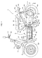
- Fig. 1 is a side view of a battery-driven electric vehicle of an embodiment of the present invention.
- Fig. 2 is a plane view of the electric vehicle.
- a seat rail 8, a fender cover 21, and a step floor 10 shown in Fig. 1 are not shown in Fig. 2 .
- a front end of a vehicle body frame F of an electric motorcycle 1 includes: a head pipe 5 which steerably supports a front fork 2 journaling a front wheel WF; and a steering handlebar 3 coupled to the front fork 2.
- the vehicle body frame F includes a center frame 6, a rear frame 7, and a seat rail 8.
- the frames 6, 7, and 8 are each structured symmetrically in pairs in the vehicle body width direction.
- the center frame 6 includes an inclined portion 6a coupled to the above head pipe 5 and extending toward the rear of the vehicle body obliquely downward and horizontal portions 6b curving at the lower end of the inclined portion 6a and extending generally horizontally toward the rear of the vehicle body. As shown in Fig. 2 , the center frame 6 is coupled by a cross member 6c for coupling the left and right horizontal portions 6b in the vehicle width direction.
- the rear frame 7 includes: first inclined portions 7a extending obliquely upward from the rear ends of the horizontal portions 6b of the center frame 6 toward the rear of the vehicle body; and second inclined portions 7c extending obliquely upward from curving portions 7b curving at the rear ends of the first inclined portions 7a toward the rear of the vehicle body at a smaller inclination than that of the first inclined portions 7a.
- first inclined portions 7a extending obliquely upward from the rear ends of the horizontal portions 6b of the center frame 6 toward the rear of the vehicle body
- second inclined portions 7c extending obliquely upward from curving portions 7b curving at the rear ends of the first inclined portions 7a toward the rear of the vehicle body at a smaller inclination than that of the first inclined portions 7a.
- the right and left second inclined portions 7c are coupled by a cross frame 7d extending in the vehicle body width direction.
- the seat rail 8 has a generally inverted U-shape attached above the rear frame 7, and includes: inclined portions 8a extending obliquely upward from the curving portions 7b of the rear frame 7 toward the forward of the vehicle body; horizontal portions 8b extending rearward from the upper ends of the inclined portions 8a; and support portions 8c extending rearward and obliquely downward from the rear portions of the horizontal portions 8b toward the second inclined portions 7c.
- batteries 9, mentioned later in details, are contained in a battery box 19.
- the battery box 19 is attached to be sandwiched by a pair of left and right frames of the horizontal portions 6b.
- the bottom surface of the battery box 19 is disposed below the horizontal portions 6b.
- the center portion of the cross member 6c of the center frame 6 in the vehicle body width direction is depressed downward.
- the battery box 19 is fixed to be mounted on this cross member 6c.
- the portion to which this battery box 19 is disposed is below a so-called foot rest space S.
- the upper side of the battery box 19 is covered with a step floor 10 for resting feet of a rider.
- the battery box 19 is formed to have a generally rectangular box shape, containing the batteries 9.
- the batteries 9 are arranged laterally.
- Air introduction ducts 20 for introducing the open air into the battery box 19 are laterally provided to the front surface of the battery box 19.
- an outlet 20b for discharging the introduced air is formed to the rear surface of the battery box 19.
- the batteries 9 are cooled by the air introduced from an inlet 20a, and the air after the cooling can be discharged from the outlet 20b.
- pivot plates 11 projecting toward the rear of the vehicle body are respectively provided to the left and right of the rear frame 7 near the coupling portion between the rear frame 7 and the center frame 6 and below the curving portions 7b.
- a pivot shaft 12 is provided penetrating the left and right pivot plates 11 in the vehicle width direction.
- the front end of a swing arm 13 is attached to the pivot shaft 12. The swing arm 13 pivots vertically about the pivot shaft 12.
- the swing arm 13 is coupled to the second inclined portion 7c of the rear frame 7 via a rear suspension 14 disposed to the left in the vehicle body width direction.
- a rear suspension 14 disposed to the left in the vehicle body width direction.
- an upper end 14a of the rear suspension 14 is attached to the second inclined portion 7c of the rear frame 7, and a lower end portion 14b of the rear suspension 14 is attached to the rear portion of the swing arm 13. Accordingly, vertical vibration of the rear wheel WR supported by the rear end of the swing arm 13 is absorbed by the rear suspension 14.
- a pair of pivot support portions 13b pivotally attached to the pivot shaft 12 are provided to the front end of the swing arm 13 while separating laterally in the vehicle body width direction. While the swing arm 13 is attached to the pivot shaft 12, the swing arm 13 extends to the rearward of the vehicle body along the left of the rear wheel WR after extending from the pivot shaft 12 (pivot support portions 13b) obliquely toward the rear of the vehicle body and obliquely left to avoid the rear wheel WR.
- a rear wheel axle 17 extending in the vehicle body width direction is provided to the rear portion of this swing arm 13.
- the rear wheel WR is rotatably cantilevered by the rear wheel axle 17.
- Figs. 1 , 2 show a headlight 41 for illuminating the forward of the vehicle body, an occupant seat 42 attached to the horizontal portions 8b of the seat rail 8, a brake light 43 attached to the rear end of the rear frame 7, and a reflector 44 disposed below the brake light 43.
- Fig. 3 is a cross sectional view taken along III-III of Fig. 1 , showing the swing arm 13 alone.
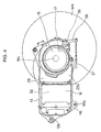
- Fig. 4 is a left side view (in the direction of A of Fig. 3 ), showing the state where a left cover (outside cover) 26 shown in Fig. 3 has been removed.
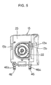
- Fig. 5 is a view of Fig. 3 seen from the forward of the vehicle body (from the direction of B of Fig. 3 ).
- the swing arm 13 is structured by assembling a body 25 having a partition wall 25a extending in the fore-and-aft direction of the vehicle body, the left cover 26 covering the left side of the body 25, and a right cover 27 covering the right side of the body 25.
- the spaces 23, 24 are respectively defined left and right in the vehicle body width direction by the above-described partition wall 25a, and structured extending in the fore-and-aft direction of the vehicle body.
- the left side of the device attachment space 23 is closed by removably attaching the above described left cover 26 by use of bolts etc.
- the right side of the air introduction space 24 is closed by removably attaching the above described right cover 27 by use of bolts etc.
- a power generating motor 16 for driving the rear wheel WR and a PDU 18 (Power Drive Unit) for controlling the power generating motor 16 are contained in the device attachment space 23.
- the maintenance of the power generating motor 16 and the PDU 18 is possible by removing the left cover 26.
- the power generating motor 16 is disposed to the rear portion of the swing arm 13, and is removably attached to a power generating motor attachment portion 33 formed to the partition wall 25a.
- a driving shaft 16a of the power generating motor 16 is disposed to the rear end of the swing arm 13 and in a width of a wheel of the rear wheel WR in the fore-and-aft direction.
- the driving shaft 16a is disposed generally in parallel to the rear wheel axle 17 of the rear wheel WR, and penetrates the partition wall 25a and projects from the device attachment space 23 to the air introduction space 24.
- a driving gear 29 is formed on the driving shaft 16a, and is in meshing engagement with a reduction gear 30 provided on the rear wheel axle 17.
- the driving gear 29 has a smaller diameter than that of the reduction gear 30, and transmits driving force of the power generating motor 16 to the rear wheel axle 17 through a single stage reduction.
- the driving gear 29 is directly coupled to the reduction gear 30, the power generating motor 16 can be disposed close to the rear wheel axle 17, and the disposition space of the power generating motor 16 can be downsized.
- the driving gear 29 and the reduction gear 30 can be coupled directly, marginal space is produced in the swing arm 13, and the PDU 18 for controlling the power generating motor 16 can be contained in this space.
- a conventional pulley provided to a motor shaft of a power generating motor, a conventional pulley provided to a rear axle, and a conventional drive belt coupling each pulley are unnecessary, the number of components can be reduced, and power transmission efficiency can be also improved.
- the driving shaft 16a is disposed close to the rear wheel axle 17, driving force can be efficiently transmitted using the minimum number of gears without increasing the number of driving gears. Additionally, to match a usage rotation zone of the power generating motor 16 and a speed zone of the vehicle, the rear wheel WR is driven via the driving gear 29. Accordingly, the power generating motor 16 does not need to be enlarged beyond necessity.
- a gear cover 34 is attached to the body 25 to cover a power transmission portion including the driving gear 29 and the reduction gear 30.
- the gear cover 34 defines a driving force transmission space 31 in which the power transmission portion is disposed and the air introduction space 24.
- the driving force transmission space 31 is sealed to permit the driving force transmission space 31 to hold lubricating oil. As described above, since the sealed driving force transmission space 31 is filled with lubricating oil, which is circulated in the power transmission portion including the driving gear 29 and the reduction gear 30, the power transmission portion is driven smoothly.
- a pin member 36 for activating a drum brake unit 35 is provided to the gear cover 34.
- the drum brake unit 35 operates by operating a brake handle 39 attached to a steering handlebar 3 on the left.
- a brake lever 38 pivots by operation of the brake handle 39 via a brake wire 37 shown in Fig. 4 , and the brake of the rear wheel WR operates by operating the pin member 36 attached to the brake lever 38.
- the PDU 18 is disposed forward of the power generating motor 16, and is removably attached, by use of bolts etc., to a PDU attachment surface 32 formed to the partition wall 25a.
- a drive circuit, a capacitor, a heat sink, etc., which are not shown, are contained in the PDU 18.
- the PDU 18 is connected to the batteries 9 by wiring, which is not shown, and electric power is sent to the PDU 18 from the batteries 9.
- the PDU 18 is also connected, by wiring, to an ECU (Electric Control Unit), which contains a control program etc. but is not shown, and a control signal is sent to the PDU 18 from the ECU.
- the PDU 18 is also connected to the power generating motor 16 by wiring, which is not shown, and electric power and a control signal are sent to the power generating motor 16 from the PDU 18.
- the ECU mentioned above is attached to the vehicle body.
- the drive circuit etc. of the PDU 18 generate a larger amount of heat as compared with other components. Therefore, the PDU 18 adheres to as a large area of the PDU attachment surface 32 of the partition wall 25a as possible. Heat generated from, e.g., the drive circuit is thermally conducted to the partition wall 25a, and released.
- cooling fins 40 project from the partition wall 25a in the air introduction space 24, and heat thermally conducted from the PDU 18 to the partition wall 25a is further thermally conducted to the cooling fins 40.
- a front opening 13a is formed to the front end of the air introduction space 24.
- a cooling fan 22 for sending air into the air introduction space 24 is attached to the front opening 13a.
- the cooling fan 22 is disposed between the above battery box 19 and the PDU 18 in the side view shown in Fig. 1 , and has a function for drawing the air in the battery box 19 from an outlet 20b.
- the outlet 20b of the battery box 19 and the front opening 13a of the swing arm 13 generally match one another in width direction and in the height direction of the vehicle body, and are opposed to one another.
- the air discharged from the outlet 20b is efficiently introduced into the front opening 13a by the cooling fan 22.
- An air hole through which the air introduction space 24 and the device attachment space 23 are in communication with one another is formed to a portion of the partition wall 25a to which the power generating motor 16 is attached. Accordingly, the air introduced from the front opening 13a flows into the power generating motor 16 from the above mentioned air hole after passing through the air introduction space 24, and is discharged to the atmosphere after cooling the inside of the power generating motor 16 by air.
- the power generating motors 16, the PDU 18, and the cooling fan 22 pivot vertically in response to pivots of the swing arm 13 together with the rear wheel WR.
- a pair of attachment portions 46 for supporting a main stand 45 are formed below the swing arm 13, the pair being separate from one another left and right in the vehicle body width direction.
- the main stand 45 is attached to the swing arm 13 by an attachment pin 46b (see Fig. 1 ) inserted into attachment holes 46a of the attachment portions 46, and pivots together with the swing arm 13.
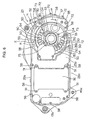
- Fig. 6 is a side view of the body 25 of the swing arm 13 seen from the left (from the device attachment space 23).
- Fig. 7 is a side view of the body 25 seen from the right (from the air introduction space 24).
- Fig. 8 is a front view of the left cover 26 seen from the body 25.
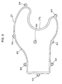
- Fig. 9 is a front view of the right cover 27 seen from the body 25.
- Fig. 10 is a side view of the gear cover 34 seen from the left (from the driving force transmission space 31).
- Fig. 11 is a side view of the gear cover 34 from the right.
- the body 25 is molded by casting using aluminum material excellent in thermal conductivity, and as shown in Figs. 6 , 7 , integrally formed from the above mentioned partition wall 25a and an upper surface portion 25b and a lower surface portion 25c vertically sandwiching the partition wall 25a.
- the partition wall 25a extends along a shape of the swing arm 13 in the vehicle body fore-and-aft direction. As shown in Fig. 6 , the PDU attachment surface 32 and the power generating motor attachment portion 33 are formed to the device attachment space 23.
- the PDU attachment surface 32 is disposed to a portion where the swing arm 13 extends obliquely from the vehicle body center portion toward the side (see Figs. 2, 3 ).
- the PDU attachment surface 32 is also formed to incline obliquely from the vehicle body center to the side from the front to rear of the vehicle body.
- the PDU attachment surface 32 and the fixing surface of the PDU 18 are each formed from a generally plane surface.
- PDU attachment holes 51 for fixing the PDU 18 with screws etc. are formed to four corners of the PDU attachment surface 32, respectively.
- the multiple air holes 50 are disposed outside the driving force transmission space 31 (see Fig. 3 ) covered with the above mentioned gear cover 34, and arranged in an arc around the penetration hole 53. Through the air holes 50, the air introduction space 24 and the device attachment space 23 are in communication with one another. Through the air holes 50, the air flowing through the air introduction space 24 flows to the power generating motor 16.
- the air introduction wall 52 is formed generally in an arc, and forms a discharge path K for introducing the air which has flown to the power generating motor 16 (indicated by an arrow H in Fig. 6 ) from left and obliquely below to right and obliquely below clockwise in the circumferential direction of the power generating motor attachment portion 33. Accordingly, after cooling a stator of the power generating motor 16, the stator being not shown, the air which has flown from the air holes 50 passes through the discharge path K and is discharged from an air discharge port 55 disposed below the body 25.
- Such a shape of the air introduction wall 52 prevents rain water and dust outside the vehicle body from entering the power generating motor attachment portion 33 from the air discharge port 55 by introducing the air in the circumferential direction of the power generating motor 16.
- Waterproof fins having a labyrinth structure are attached near the air discharge port 55 to further prevent rain water and dust from entering the power generating motor attachment portion 33 from the air discharge port 55.
- the multiple cooling fins 40 projecting from the partition wall 25a toward the air introduction space 24 are integrally formed to the partition wall 25a.
- the multiple cooling fins 40 pass from the front opening 13a through near the back side of the power generating motor attachment portion 33, and are curved in an arc along a circumference, which is an outside shape of the power generating motor 16. Then, the cooling fins 40 extend to the multiple air holes 50.
- the shapes of the fins have a function for introducing the air introduced from the front opening 13a to each of the air holes 50 through between the adjacent cooling fins 40.
- the cooling fins 40 extend from the back side of the PDU attachment surface 32 to the back side of the power generating motor attachment portion 33 to have a function for efficiently absorbing and releasing heat of the partition wall 25a corresponding to the back sides.
- the larger area of the partition wall 25a is in contact with the air by providing the multiple cooling fins 40. Accordingly, the cooling fins 40 function to release heat from the partition wall 25a efficiently.
- a receiving portion 57 supporting a bearing attached to the left end of the rear wheel axle 17 is formed to the partition wall 25a.
- FIG. 6 viewed from the device attachment space 23
- multiple attachment holes 58 for attaching the left cover 26 are formed to an edge 56 of the upper surface portion 25b and the lower surface portion 25c.
- attachment holes 60 penetrating the outer surface of the left cover 26 are also formed to an edge 59 of the inner surface of the left cover 26 correspondingly to the attachment holes 58.
- the left cover 26 may be integrally molded with an aluminum casting having excellent thermal conductivity, and may be integrally molded with a molded product made of resin.
- attachment holes 62 for attaching the right cover 27 are also formed to edges 61 of the upper surface portion 25b and the lower surface portion 25c and to the central portion of the body 25.
- attachment holes 64 penetrating the outer surface of the right cover 27 are also formed to an edge 63 of the inner surface of the right cover 27 and the central portion of the right cover 27 correspondingly to the attachment holes 62.
- the right cover 27 can be removably attached to the body 25 by inserting bolts etc. into the attachment holes 64 and screwing the bolts etc. into the attachment holes 62.
- a rear end portion 27a of the right cover 27 is formed in a generally arc, concave shape to avoid the rear wheel axle 17 in the assembled state.
- the right cover 27 may be integrally molded with an aluminum casting having excellent thermal conductivity, and may be also integrally molded with a molded product made of resin.
- the attachment holes 46a for attaching the above described main stand 45 are formed to the lower portion of the front of the body 25, which is the lower surface portion 25c.
- a flat attachment surface 71 for attaching the gear cover 34 is formed to the body 25.
- Multiple attachment holes 72 for attaching the gear cover 34 and multiple knock holes 73 for inserting knock pins (not shown) are formed to the attachment surface 71.
- a flat attachment surface 74 having the generally same shape as the attachment surface 71 is formed to the gear cover 34 correspondingly to the attachment surface 71 of the body 25.
- Attachment holes 75 penetrating the outer surface of the gear cover 34 are formed to the attachment surface 74 correspondingly to the attachment holes 72 of the body 25.
- Knock holes 76 are formed to the attachment surface 74 correspondingly to the knock holes 73 of the body 25.
- a gasket having generally the same shape as the attachment surfaces 71, 74 but not shown are disposed between the gear cover 34 and the body 25. Attachment holes (not shown) corresponding to the attachment holes 72, 75 and knock holes (not shown) corresponding to the knock holes 73, 76 are formed to the gasket.
- the knock pins (not shown) are inserted in the knock holes 73 of the body 25, respectively, and the knock holes open to the gasket are hooked by the knock pins projecting from the attachment surface 71.
- the gear cover 34 is removably attached to the body 25 by inserting the knock pins which project from the attachment surface 71 into the knock holes 76, inserting, e.g., bolts into the attachment holes 75, and screwing, e.g., the bolts into the attachment holes 72 of the body 25.
- the driving force transmission space 31 is formed from the body 25 and the gear cover 34.
- a receiving portion 77 supporting a bearing attached to the right end of the power generating motor 16, a penetration hole 78 through which the rear wheel axle 17 (see Fig. 3 ) passes, a penetration hole (not shown) through which the above-mentioned pin member 36 passes, and a penetration hole 79 through which an attachment bolt of the mentioned above right cover 27 (see Fig. 9 ) passes are formed to the gear cover 34.
- the gear cover 34 is molded by casting using aluminum material excellent in thermal conductivity. As shown in Fig. 11 , multiple ribs 82 are formed to the gear cover 34 to obtain sufficient strength to support the above-mentioned drum brake unit 35.
- An oil fill port 80 is formed to the gear cover 34.
- the driving force transmission space 31 is filled with lubricating oil through the oil fill port 80.
- oil seals 81 for preventing lubricating oil from leaking to the outside of the driving force transmission space 31 are provided around the rear wheel axle 17 penetrating the gear cover 34 and around the driving shaft 16a penetrating the partition wall 25a, respectively. Therefore, the driving force transmission space 31 is sealed with the gasket (not shown) disposed between the body 25 and the gear cover 34 and with the oil seals 81.
- the electric motorcycle 1 of the embodiment of the present invention is as follows.
- the driving shaft 16a of the power generating motor 16 is disposed generally in parallel to the rear wheel axle 17 of the rear wheel WR.
- the driving gear 29 is provided on the driving shaft 16a, and in meshing engagement with the reduction gear 30 provided on the rear wheel axle 17.
- the driving gear 29 has a smaller diameter than that of the reduction gear 30.
- Driving force of the power generating motor 16 is transmitted to the rear wheel axle 17 through a reduction to directly couple the driving gear 29 and the reduction gear 30. Accordingly, the power generating motor 16 can be disposed close to the rear wheel axle 17, and the disposition space of the power generating motor 16 can be downsized. Since a conventional pulley provided to a power generating motor, a conventional pulley provided to a rear wheel axle, and a conventional drive belt coupling each pulley are unnecessary, the number of components can be reduced, and power transmission efficiency can also be improved.
- the gear cover 34 is provided to cover the power transmission portion including the driving gear 29 and the reduction gear 30.
- the inside of the gear cover 34 is sealed, and the driving force transmission space 31 is filled with lubricating oil, which is circulated in the power transmission portion including the driving gear 29 and the reduction gear 30. Accordingly, the power transmission portion is driven smoothly.
- the driving gear 29 and the reduction gear 30 are coupled directly to produce marginal space in the swing arm 13.
- the PDU 18 for controlling the power generating motor 16 can be contained in the marginal space.
- the power generating motor 16 is disposed close to the rear wheel axle 17, and the disposition space of the power generating motor 16 can be downsized. Since the gear cover 34 defines the driving force transmission space 31 and the air introduction space 24, the inside of the driving force transmission space 31 can be filled with the lubricating oil.
- the driving shaft 16a is disposed, in planar view, to the rear end of the swing arm 13 and within the width of the rear wheel WR in the fore-and-aft direction, the driving shaft 16a is disposed close to the rear wheel axle 17. Without increasing the number of gears, driving force can be transmitted efficiently by use of the minimum number of gears.
- the rear wheel WR is driven via the driving gear 29 to match the usage rotation zone of the power generating motor 16 and the speed zone of the vehicle. It is not necessary to enlarge the power generating motor 16 beyond necessity.
- the present invention is directed to provide an electric motorcycle in which disposition space of a motor is downsized, the number of components are reduced, and power transmission efficiency is improved.
- a swing arm 13 swingably supported by a vehicle body frame supports a power generating motor 16, and a driving shaft 16a of the power generating motor 16 and a rear wheel axle 17 of a rear wheel WR are coupled, and driving force of the power generating motor 16 is transmitted to the rear wheel WR.
- the driving shaft 16a of the power generating motor 16 is disposed generally in parallel to the rear wheel axle 17 of the rear wheel WR, a driving gear 29 is provided on the driving shaft 16a, a driving gear 29 is in meshing engagement with a reduction gear 30 provided on the rear wheel axle 17, the driving gear 29 has a smaller diameter than that of the reduction gear 30, and driving force of the power generating motor 16 is transmitted to the rear wheel axle 17 through a reduction.
Landscapes
- Engineering & Computer Science (AREA)
- Transportation (AREA)
- Mechanical Engineering (AREA)
- Chemical & Material Sciences (AREA)
- Combustion & Propulsion (AREA)
- Life Sciences & Earth Sciences (AREA)
- Sustainable Development (AREA)
- Sustainable Energy (AREA)
- Power Engineering (AREA)
- Arrangement Or Mounting Of Propulsion Units For Vehicles (AREA)
- Gear Transmission (AREA)
- Electric Propulsion And Braking For Vehicles (AREA)
Abstract
Description
- The present invention relates to an electric motorcycle driven by a power generating motor.
- In the past, an electric motorcycle carrying a battery which supplies power source to drive a power generating motor for traveling is known. In such an electric motorcycle, a pulley provided to a motor shaft of a power generating motor and a pulley provided to a rear wheel axle are coupled by a drive belt. Driving force of the power generating motor is transmitted to the rear wheel axle via the drive belt (for example, see Patent document No.
JP-A-04-257783 - However, in the above-mentioned conventional electric motorcycle, since the power generating motor is disposed separately from the rear wheel axle, the disposition space of the power generating motor is large. Since the pulley provided to the motor shaft of the power generating motor, the pulley provided to the rear wheel axle, and the drive belt coupling each pulley are necessary, the number of components is large and power transmission efficiency is necessarily improved.
- In view of the situation mentioned above, the present invention is made to provide an electric motorcycle in which disposition space of a motor is downsized, the number of components is reduced, and power transmission efficiency is improved.
- For addressing the above problem, in an electric motorcycle of the present invention, a swing arm swingably supported by a vehicle body frame supports a power generating motor, a driving shaft of the power generating motor and a rear wheel axle of a rear wheel are coupled to transmit driving force of the power generating motor to the rear wheel. The driving shaft of the power generating motor is disposed generally in parallel to the rear wheel axle of the rear wheel. A driving gear is provided on the driving shaft. The driving gear is in meshing engagement with a reduction gear provided on the rear wheel axle. The driving gear has a smaller diameter than that of the reduction gear. The driving force of the power generating motor is transmitted to the rear wheel axle through a reduction.
- In the present invention, since the driving gear is directly coupled to the reduction gear, the power generating motor can be disposed close to the rear wheel axle, and disposition space of the power generating motor can be downsized. Since a conventional pulley provided to a motor shaft of a power generating motor, a conventional pulley provided to a rear wheel axle, and a conventional drive belt coupling each pulley are unnecessary, the number of components can be reduced, and power transmission efficiency can also be improved.
- In this case, a gear cover may be provided to cover a power transmission portion including the driving gear and the reduction gear. The inside of the gear cover may be sealed. The driving force transmission space may be filled with lubricating oil.
- Since the driving force transmission space is filled with lubricating oil, which is circulated in the power transmission portion including the driving gear and the reduction gear, the power transmission portion is driven smoothly.
- A device attachment space disposed to the outer side of the vehicle body and air introduction space disposed to the inner side of the vehicle body are formed by a partition wall inside the swing arm. The power generating motor and a PDU for controlling the power generating motor are contained in the device attachment space. A driving shaft of the power generating motor penetrates the partition wall from the device attachment space to the air introduction space. The gear cover may define a driving force transmission space and an air introduction space. The PDU may be disposed forward of the power generating motor in the vehicle body. By directly coupling the driving gear and the reduction gear, marginal space is generated in the swing arm. The PDU for controlling the power generating motor can be contained in this space, the power generating motor can be disposed close to the rear wheel axle, and disposition space of the power generating motor can be downsized. Since the gear cover defines the driving force transmission space and the air introduction space, the inside of the driving force transmission space can be filled with lubricating oil.
- In planar view, the driving shaft may be disposed to the rear end of the swing arm and within the wheel width of the rear wheel in the fore-and-aft direction.
- The driving force can be efficiently transmitted using the minimum number of gears without increasing the number of driving gears because the driving shaft is disposed close to the rear wheel axle. In addition, by driving the rear wheel via the driving gear to match a usage rotation zone of the power generating motor and a speed zone of the vehicle, it also becomes unnecessary to enlarge the power generating motor more than needed.
- In the present invention, a driving shaft of a power generating motor is disposed generally in parallel to a rear wheel axle of a rear wheel, a driving gear is provided on the driving shaft, the driving gear is in meshing engagement with a reduction gear provided on the rear wheel axle, the driving gear has a smaller diameter than that of the reduction gear, and driving force of the power generating motor is transmitted to the rear wheel axle. Accordingly, since the driving gear is directly coupled to the reduction gear, the power generating motor can be disposed close to the rear wheel axle, and the disposition space of the power generating motor can be downsized. Since a conventional pulley provided in a motor shaft of a power generating motor, a conventional pulley provided to a rear wheel axle, and a conventional drive belt connecting each belt pulley are unnecessary, the number of components can be reduced and power transmission efficiency can also be improved.
- Since a gear cover is provided to cover a power transmission portion including the driving gear and the reduction gear, the inside of the gear cover is sealed, and driving force transmission space is filled with lubricating oil, which is circulated in the power transmission portion including the driving gear and the reduction gear, the power transmission portion is driven smoothly.
- Further, by coupling the driving gear and the reduction gear directly, marginal space is produced inside the swing arm and can contain a PDU for controlling the power generating motor, the power generating motor can be disposed close to the rear wheel axle, and the disposition space of the power generating motor can be downsized. Since the gear cover defines a driving force transmission space and an air introduction space, the inside of the driving force transmission space can be filled with lubricating oil.
- Driving force can be efficiently transmitted using the minimum number of gears without increasing the number of driving gears because the driving shaft is disposed to the rear end of the swing arm and in the width of the rear wheel in the fore-and-aft direction in planar view and is disposed close to the rear wheel axle. In addition, by driving the rear wheel via the driving gear to match the usage rotation zone of the power generating motor and the speed zone of the vehicle, it also becomes unnecessary to enlarge the power generating motor more than needed.
-
-
Fig. 1 is a side view of an electric motorcycle of an embodiment of the present invention. -
Fig. 2 is a planar view ofFig. 1 . -
Fig. 3 is a sectional view of III-III ofFig. 1 , and shows a swing arm alone. -
Fig. 4 is a right side view ofFig. 3 . -
Fig. 5 is a view ofFig. 3 seen from a front of a vehicle. -
Fig. 6 is a side view of a body from a device attachment space. -
Fig. 7 is a side view of the body from an air introduction space side. -
Fig. 8 is a front view of a left cover. -
Fig. 9 is a front view of a right cover. -
Fig. 10 is a side view of a gear cover seen from the left side (from a driving force transmission space). -
Fig. 11 is a side view of the gear cover seen from the right side. - An electric motorcycle of an embodiment of the present invention is explained below in reference to the drawings. Vertical, fore-and-aft, and left-and-right directions described in the following explanation are ones seen from a driver.
-
Fig. 1 is a side view of a battery-driven electric vehicle of an embodiment of the present invention.Fig. 2 is a plane view of the electric vehicle. For ease of explanation, aseat rail 8, afender cover 21, and a step floor 10 shown inFig. 1 are not shown inFig. 2 . - As shown in
Fig. 1 , a front end of a vehicle body frame F of an electric motorcycle 1 includes: a head pipe 5 which steerably supports a front fork 2 journaling a front wheel WF; and a steering handlebar 3 coupled to the front fork 2. The vehicle body frame F includes acenter frame 6, arear frame 7, and aseat rail 8. As shown inFig. 2 , theframes - The
center frame 6 includes aninclined portion 6a coupled to the above head pipe 5 and extending toward the rear of the vehicle body obliquely downward andhorizontal portions 6b curving at the lower end of theinclined portion 6a and extending generally horizontally toward the rear of the vehicle body. As shown inFig. 2 , thecenter frame 6 is coupled by across member 6c for coupling the left and righthorizontal portions 6b in the vehicle width direction. - The
rear frame 7 includes: firstinclined portions 7a extending obliquely upward from the rear ends of thehorizontal portions 6b of thecenter frame 6 toward the rear of the vehicle body; and secondinclined portions 7c extending obliquely upward from curvingportions 7b curving at the rear ends of the firstinclined portions 7a toward the rear of the vehicle body at a smaller inclination than that of the firstinclined portions 7a. As shown inFig. 2 , the right and left secondinclined portions 7c are coupled by across frame 7d extending in the vehicle body width direction. - Further, the
seat rail 8 has a generally inverted U-shape attached above therear frame 7, and includes:inclined portions 8a extending obliquely upward from the curvingportions 7b of therear frame 7 toward the forward of the vehicle body;horizontal portions 8b extending rearward from the upper ends of theinclined portions 8a; andsupport portions 8c extending rearward and obliquely downward from the rear portions of thehorizontal portions 8b toward the secondinclined portions 7c. - As shown in
Figs. 1 ,2 , in thehorizontal portions 6b of thecenter frame 6,batteries 9, mentioned later in details, are contained in abattery box 19. Thebattery box 19 is attached to be sandwiched by a pair of left and right frames of thehorizontal portions 6b. In the side view shown inFig. 1 , the bottom surface of thebattery box 19 is disposed below thehorizontal portions 6b. The center portion of thecross member 6c of thecenter frame 6 in the vehicle body width direction is depressed downward. Thebattery box 19 is fixed to be mounted on thiscross member 6c. - The portion to which this
battery box 19 is disposed is below a so-called foot rest space S. The upper side of thebattery box 19 is covered with a step floor 10 for resting feet of a rider. - The
battery box 19 is formed to have a generally rectangular box shape, containing thebatteries 9. In thebattery box 19, thebatteries 9 are arranged laterally.Air introduction ducts 20 for introducing the open air into thebattery box 19 are laterally provided to the front surface of thebattery box 19. On the other hand, anoutlet 20b for discharging the introduced air is formed to the rear surface of thebattery box 19. - Accordingly, the
batteries 9 are cooled by the air introduced from aninlet 20a, and the air after the cooling can be discharged from theoutlet 20b. - As shown in
Fig. 1 ,pivot plates 11 projecting toward the rear of the vehicle body are respectively provided to the left and right of therear frame 7 near the coupling portion between therear frame 7 and thecenter frame 6 and below the curvingportions 7b. Apivot shaft 12 is provided penetrating the left andright pivot plates 11 in the vehicle width direction. The front end of aswing arm 13 is attached to thepivot shaft 12. Theswing arm 13 pivots vertically about thepivot shaft 12. - The
swing arm 13 is coupled to the secondinclined portion 7c of therear frame 7 via arear suspension 14 disposed to the left in the vehicle body width direction. For more details, anupper end 14a of therear suspension 14 is attached to the secondinclined portion 7c of therear frame 7, and alower end portion 14b of therear suspension 14 is attached to the rear portion of theswing arm 13. Accordingly, vertical vibration of the rear wheel WR supported by the rear end of theswing arm 13 is absorbed by therear suspension 14. - A pair of
pivot support portions 13b pivotally attached to thepivot shaft 12 are provided to the front end of theswing arm 13 while separating laterally in the vehicle body width direction. While theswing arm 13 is attached to thepivot shaft 12, theswing arm 13 extends to the rearward of the vehicle body along the left of the rear wheel WR after extending from the pivot shaft 12 (pivot support portions 13b) obliquely toward the rear of the vehicle body and obliquely left to avoid the rear wheel WR. Arear wheel axle 17 extending in the vehicle body width direction is provided to the rear portion of thisswing arm 13. The rear wheel WR is rotatably cantilevered by therear wheel axle 17. -
Figs. 1 ,2 show aheadlight 41 for illuminating the forward of the vehicle body, anoccupant seat 42 attached to thehorizontal portions 8b of theseat rail 8, abrake light 43 attached to the rear end of therear frame 7, and areflector 44 disposed below thebrake light 43. -
Fig. 3 is a cross sectional view taken along III-III ofFig. 1 , showing theswing arm 13 alone.Fig. 4 is a left side view (in the direction of A ofFig. 3 ), showing the state where a left cover (outside cover) 26 shown inFig. 3 has been removed. Further,Fig. 5 is a view ofFig. 3 seen from the forward of the vehicle body (from the direction of B ofFig. 3 ). - As shown in
Fig. 3 , theswing arm 13 is structured by assembling abody 25 having apartition wall 25a extending in the fore-and-aft direction of the vehicle body, theleft cover 26 covering the left side of thebody 25, and aright cover 27 covering the right side of thebody 25. - Two spaces, a
device attachment space 23 disposed to the left of the vehicle body (the outer side of the vehicle body) and anair introduction space 24 disposed to the right of the vehicle body (the inner side of the vehicle body), are formed inside theswing arm 13. Thespaces partition wall 25a, and structured extending in the fore-and-aft direction of the vehicle body. - The left side of the
device attachment space 23 is closed by removably attaching the above describedleft cover 26 by use of bolts etc. Similarly, the right side of theair introduction space 24 is closed by removably attaching the above describedright cover 27 by use of bolts etc. - A
power generating motor 16 for driving the rear wheel WR and a PDU 18 (Power Drive Unit) for controlling thepower generating motor 16 are contained in thedevice attachment space 23. The maintenance of thepower generating motor 16 and thePDU 18 is possible by removing theleft cover 26. - As shown in
Fig. 3 , thepower generating motor 16 is disposed to the rear portion of theswing arm 13, and is removably attached to a power generatingmotor attachment portion 33 formed to thepartition wall 25a. In planar view, a drivingshaft 16a of thepower generating motor 16 is disposed to the rear end of theswing arm 13 and in a width of a wheel of the rear wheel WR in the fore-and-aft direction. The drivingshaft 16a is disposed generally in parallel to therear wheel axle 17 of the rear wheel WR, and penetrates thepartition wall 25a and projects from thedevice attachment space 23 to theair introduction space 24. Adriving gear 29 is formed on the drivingshaft 16a, and is in meshing engagement with areduction gear 30 provided on therear wheel axle 17. Thedriving gear 29 has a smaller diameter than that of thereduction gear 30, and transmits driving force of thepower generating motor 16 to therear wheel axle 17 through a single stage reduction. - That is, since the
driving gear 29 is directly coupled to thereduction gear 30, thepower generating motor 16 can be disposed close to therear wheel axle 17, and the disposition space of thepower generating motor 16 can be downsized. By coupling thedriving gear 29 and thereduction gear 30 directly, marginal space is produced in theswing arm 13, and thePDU 18 for controlling thepower generating motor 16 can be contained in this space. Further, since a conventional pulley provided to a motor shaft of a power generating motor, a conventional pulley provided to a rear axle, and a conventional drive belt coupling each pulley are unnecessary, the number of components can be reduced, and power transmission efficiency can be also improved. - Since the driving
shaft 16a is disposed close to therear wheel axle 17, driving force can be efficiently transmitted using the minimum number of gears without increasing the number of driving gears. Additionally, to match a usage rotation zone of thepower generating motor 16 and a speed zone of the vehicle, the rear wheel WR is driven via thedriving gear 29. Accordingly, thepower generating motor 16 does not need to be enlarged beyond necessity. - A
gear cover 34 is attached to thebody 25 to cover a power transmission portion including thedriving gear 29 and thereduction gear 30. Thegear cover 34 defines a drivingforce transmission space 31 in which the power transmission portion is disposed and theair introduction space 24. The drivingforce transmission space 31 is sealed to permit the drivingforce transmission space 31 to hold lubricating oil. As described above, since the sealed drivingforce transmission space 31 is filled with lubricating oil, which is circulated in the power transmission portion including thedriving gear 29 and thereduction gear 30, the power transmission portion is driven smoothly. - A
pin member 36 for activating adrum brake unit 35 is provided to thegear cover 34. Thedrum brake unit 35 operates by operating abrake handle 39 attached to a steering handlebar 3 on the left. For more details, abrake lever 38 pivots by operation of the brake handle 39 via abrake wire 37 shown inFig. 4 , and the brake of the rear wheel WR operates by operating thepin member 36 attached to thebrake lever 38. - As shown in
Figs. 2 ,3 , thePDU 18 is disposed forward of thepower generating motor 16, and is removably attached, by use of bolts etc., to aPDU attachment surface 32 formed to thepartition wall 25a. A drive circuit, a capacitor, a heat sink, etc., which are not shown, are contained in thePDU 18. - The
PDU 18 is connected to thebatteries 9 by wiring, which is not shown, and electric power is sent to thePDU 18 from thebatteries 9. ThePDU 18 is also connected, by wiring, to an ECU (Electric Control Unit), which contains a control program etc. but is not shown, and a control signal is sent to thePDU 18 from the ECU. Further, thePDU 18 is also connected to thepower generating motor 16 by wiring, which is not shown, and electric power and a control signal are sent to thepower generating motor 16 from thePDU 18. The ECU mentioned above is attached to the vehicle body. - The drive circuit etc. of the
PDU 18 generate a larger amount of heat as compared with other components. Therefore, thePDU 18 adheres to as a large area of thePDU attachment surface 32 of thepartition wall 25a as possible. Heat generated from, e.g., the drive circuit is thermally conducted to thepartition wall 25a, and released. - On the other hand, multiple cooling
fins 40 project from thepartition wall 25a in theair introduction space 24, and heat thermally conducted from thePDU 18 to thepartition wall 25a is further thermally conducted to the coolingfins 40. - A
front opening 13a is formed to the front end of theair introduction space 24. A coolingfan 22 for sending air into theair introduction space 24 is attached to thefront opening 13a. The coolingfan 22 is disposed between theabove battery box 19 and thePDU 18 in the side view shown inFig. 1 , and has a function for drawing the air in thebattery box 19 from anoutlet 20b. In other words, theoutlet 20b of thebattery box 19 and thefront opening 13a of theswing arm 13 generally match one another in width direction and in the height direction of the vehicle body, and are opposed to one another. The air discharged from theoutlet 20b is efficiently introduced into thefront opening 13a by the coolingfan 22. - An air hole through which the
air introduction space 24 and thedevice attachment space 23 are in communication with one another is formed to a portion of thepartition wall 25a to which thepower generating motor 16 is attached. Accordingly, the air introduced from thefront opening 13a flows into thepower generating motor 16 from the above mentioned air hole after passing through theair introduction space 24, and is discharged to the atmosphere after cooling the inside of thepower generating motor 16 by air. - The
power generating motors 16, thePDU 18, and the coolingfan 22 pivot vertically in response to pivots of theswing arm 13 together with the rear wheel WR. - As shown in
Fig. 5 , a pair ofattachment portions 46 for supporting amain stand 45 are formed below theswing arm 13, the pair being separate from one another left and right in the vehicle body width direction. Thus, themain stand 45 is attached to theswing arm 13 by anattachment pin 46b (seeFig. 1 ) inserted intoattachment holes 46a of theattachment portions 46, and pivots together with theswing arm 13. -
Fig. 6 is a side view of thebody 25 of theswing arm 13 seen from the left (from the device attachment space 23).Fig. 7 is a side view of thebody 25 seen from the right (from the air introduction space 24).Fig. 8 is a front view of theleft cover 26 seen from thebody 25.Fig. 9 is a front view of theright cover 27 seen from thebody 25.Fig. 10 is a side view of thegear cover 34 seen from the left (from the driving force transmission space 31).Fig. 11 is a side view of the gear cover 34 from the right. - The
body 25 is molded by casting using aluminum material excellent in thermal conductivity, and as shown inFigs. 6 ,7 , integrally formed from the above mentionedpartition wall 25a and anupper surface portion 25b and alower surface portion 25c vertically sandwiching thepartition wall 25a. - The
partition wall 25a extends along a shape of theswing arm 13 in the vehicle body fore-and-aft direction. As shown inFig. 6 , thePDU attachment surface 32 and the power generatingmotor attachment portion 33 are formed to thedevice attachment space 23. ThePDU attachment surface 32 is disposed to a portion where theswing arm 13 extends obliquely from the vehicle body center portion toward the side (seeFigs. 2, 3 ). ThePDU attachment surface 32 is also formed to incline obliquely from the vehicle body center to the side from the front to rear of the vehicle body. ThePDU attachment surface 32 and the fixing surface of thePDU 18 are each formed from a generally plane surface. The fixing surface ofPDU 18 and thePDU attachment surface 32 adhere to one another, and the adhesion surface is made large to increase thermal conductivity. PDU attachment holes 51 for fixing thePDU 18 with screws etc. are formed to four corners of thePDU attachment surface 32, respectively. - Multiple air holes 50 through which the
air introduction space 24 and thedevice attachment space 23 are in communication with one another, anair introduction wall 52 for introducing the air entering from themultiple air holes 50 in the circumferential direction of thepower generating motor 16, and apenetration hole 53 through which the drivingshaft 16a of thepower generating motor 16 passes are formed to the power generatingmotor attachment portion 33. Attachment holes 54 for attaching the above mentionedpower generating motor 16 are formed around thepenetration hole 53. - The
multiple air holes 50 are disposed outside the driving force transmission space 31 (seeFig. 3 ) covered with the above mentionedgear cover 34, and arranged in an arc around thepenetration hole 53. Through the air holes 50, theair introduction space 24 and thedevice attachment space 23 are in communication with one another. Through the air holes 50, the air flowing through theair introduction space 24 flows to thepower generating motor 16. - As shown in
Fig. 6 , theair introduction wall 52 is formed generally in an arc, and forms a discharge path K for introducing the air which has flown to the power generating motor 16 (indicated by an arrow H inFig. 6 ) from left and obliquely below to right and obliquely below clockwise in the circumferential direction of the power generatingmotor attachment portion 33. Accordingly, after cooling a stator of thepower generating motor 16, the stator being not shown, the air which has flown from the air holes 50 passes through the discharge path K and is discharged from anair discharge port 55 disposed below thebody 25. - Such a shape of the
air introduction wall 52 prevents rain water and dust outside the vehicle body from entering the power generatingmotor attachment portion 33 from theair discharge port 55 by introducing the air in the circumferential direction of thepower generating motor 16. - Waterproof fins having a labyrinth structure are attached near the
air discharge port 55 to further prevent rain water and dust from entering the power generatingmotor attachment portion 33 from theair discharge port 55. - As shown in
Fig. 7 , themultiple cooling fins 40 projecting from thepartition wall 25a toward the air introduction space 24 (opposed to the device attachment space 23) are integrally formed to thepartition wall 25a. Themultiple cooling fins 40 pass from thefront opening 13a through near the back side of the power generatingmotor attachment portion 33, and are curved in an arc along a circumference, which is an outside shape of thepower generating motor 16. Then, the coolingfins 40 extend to the multiple air holes 50. The shapes of the fins have a function for introducing the air introduced from thefront opening 13a to each of the air holes 50 through between theadjacent cooling fins 40. The coolingfins 40 extend from the back side of thePDU attachment surface 32 to the back side of the power generatingmotor attachment portion 33 to have a function for efficiently absorbing and releasing heat of thepartition wall 25a corresponding to the back sides. The larger area of thepartition wall 25a is in contact with the air by providing themultiple cooling fins 40. Accordingly, the coolingfins 40 function to release heat from thepartition wall 25a efficiently. - Further, as shown in
Fig. 7 , a receivingportion 57 supporting a bearing attached to the left end of therear wheel axle 17 is formed to thepartition wall 25a. - On the other hand, as shown in
Fig. 6 , viewed from thedevice attachment space 23, multiple attachment holes 58 for attaching theleft cover 26 are formed to anedge 56 of theupper surface portion 25b and thelower surface portion 25c. In response, as shown inFig. 8 , attachment holes 60 penetrating the outer surface of theleft cover 26 are also formed to anedge 59 of the inner surface of theleft cover 26 correspondingly to the attachment holes 58. By inserting, e.g., bolts into theattachment 60 to screw, e.g., the bolts into the attachment holes 58, theleft cover 26 is removably attached to thebody 25. - The
left cover 26 may be integrally molded with an aluminum casting having excellent thermal conductivity, and may be integrally molded with a molded product made of resin. - Similarly, as shown in
Fig. 7 , viewed from theair introduction space 24, multiple attachment holes 62 for attaching theright cover 27 are also formed to edges 61 of theupper surface portion 25b and thelower surface portion 25c and to the central portion of thebody 25. In response, as shown inFig. 9 , attachment holes 64 penetrating the outer surface of theright cover 27 are also formed to anedge 63 of the inner surface of theright cover 27 and the central portion of theright cover 27 correspondingly to the attachment holes 62. Theright cover 27 can be removably attached to thebody 25 by inserting bolts etc. into the attachment holes 64 and screwing the bolts etc. into the attachment holes 62. - As shown in
Fig. 9 , arear end portion 27a of theright cover 27 is formed in a generally arc, concave shape to avoid therear wheel axle 17 in the assembled state. - The
right cover 27 may be integrally molded with an aluminum casting having excellent thermal conductivity, and may be also integrally molded with a molded product made of resin. - As shown in
Figs. 6 ,7 , the attachment holes 46a for attaching the above describedmain stand 45 are formed to the lower portion of the front of thebody 25, which is thelower surface portion 25c. - In addition, as shown in
Fig. 7 , aflat attachment surface 71 for attaching thegear cover 34 is formed to thebody 25. Multiple attachment holes 72 for attaching thegear cover 34 and multiple knock holes 73 for inserting knock pins (not shown) are formed to theattachment surface 71. On the other hand, as shown inFig. 10 , aflat attachment surface 74 having the generally same shape as theattachment surface 71 is formed to thegear cover 34 correspondingly to theattachment surface 71 of thebody 25. Attachment holes 75 penetrating the outer surface of thegear cover 34 are formed to theattachment surface 74 correspondingly to the attachment holes 72 of thebody 25. Knock holes 76 are formed to theattachment surface 74 correspondingly to the knock holes 73 of thebody 25. - A gasket having generally the same shape as the attachment surfaces 71, 74 but not shown are disposed between the
gear cover 34 and thebody 25. Attachment holes (not shown) corresponding to the attachment holes 72, 75 and knock holes (not shown) corresponding to the knock holes 73, 76 are formed to the gasket. - When the
gear cover 34 is attached to thebody 25, the knock pins (not shown) are inserted in the knock holes 73 of thebody 25, respectively, and the knock holes open to the gasket are hooked by the knock pins projecting from theattachment surface 71. Thegear cover 34 is removably attached to thebody 25 by inserting the knock pins which project from theattachment surface 71 into the knock holes 76, inserting, e.g., bolts into the attachment holes 75, and screwing, e.g., the bolts into the attachment holes 72 of thebody 25. The drivingforce transmission space 31 is formed from thebody 25 and thegear cover 34. - Further, a receiving
portion 77 supporting a bearing attached to the right end of thepower generating motor 16, apenetration hole 78 through which the rear wheel axle 17 (seeFig. 3 ) passes, a penetration hole (not shown) through which the above-mentionedpin member 36 passes, and apenetration hole 79 through which an attachment bolt of the mentioned above right cover 27 (seeFig. 9 ) passes are formed to thegear cover 34. Thegear cover 34 is molded by casting using aluminum material excellent in thermal conductivity. As shown inFig. 11 ,multiple ribs 82 are formed to thegear cover 34 to obtain sufficient strength to support the above-mentioneddrum brake unit 35. - An
oil fill port 80 is formed to thegear cover 34. The drivingforce transmission space 31 is filled with lubricating oil through theoil fill port 80. As shown inFig. 3 , oil seals 81 for preventing lubricating oil from leaking to the outside of the drivingforce transmission space 31 are provided around therear wheel axle 17 penetrating thegear cover 34 and around the drivingshaft 16a penetrating thepartition wall 25a, respectively. Therefore, the drivingforce transmission space 31 is sealed with the gasket (not shown) disposed between thebody 25 and thegear cover 34 and with the oil seals 81. - As explained above, the electric motorcycle 1 of the embodiment of the present invention is as follows. The driving
shaft 16a of thepower generating motor 16 is disposed generally in parallel to therear wheel axle 17 of the rear wheel WR. Thedriving gear 29 is provided on the drivingshaft 16a, and in meshing engagement with thereduction gear 30 provided on therear wheel axle 17. Thedriving gear 29 has a smaller diameter than that of thereduction gear 30. Driving force of thepower generating motor 16 is transmitted to therear wheel axle 17 through a reduction to directly couple thedriving gear 29 and thereduction gear 30. Accordingly, thepower generating motor 16 can be disposed close to therear wheel axle 17, and the disposition space of thepower generating motor 16 can be downsized. Since a conventional pulley provided to a power generating motor, a conventional pulley provided to a rear wheel axle, and a conventional drive belt coupling each pulley are unnecessary, the number of components can be reduced, and power transmission efficiency can also be improved. - The
gear cover 34 is provided to cover the power transmission portion including thedriving gear 29 and thereduction gear 30. The inside of thegear cover 34 is sealed, and the drivingforce transmission space 31 is filled with lubricating oil, which is circulated in the power transmission portion including thedriving gear 29 and thereduction gear 30. Accordingly, the power transmission portion is driven smoothly. - Further, the
driving gear 29 and thereduction gear 30 are coupled directly to produce marginal space in theswing arm 13. ThePDU 18 for controlling thepower generating motor 16 can be contained in the marginal space. Thepower generating motor 16 is disposed close to therear wheel axle 17, and the disposition space of thepower generating motor 16 can be downsized. Since thegear cover 34 defines the drivingforce transmission space 31 and theair introduction space 24, the inside of the drivingforce transmission space 31 can be filled with the lubricating oil. - Since the driving
shaft 16a is disposed, in planar view, to the rear end of theswing arm 13 and within the width of the rear wheel WR in the fore-and-aft direction, the drivingshaft 16a is disposed close to therear wheel axle 17. Without increasing the number of gears, driving force can be transmitted efficiently by use of the minimum number of gears. In addition, the rear wheel WR is driven via thedriving gear 29 to match the usage rotation zone of thepower generating motor 16 and the speed zone of the vehicle. It is not necessary to enlarge thepower generating motor 16 beyond necessity. - The present invention is directed to provide an electric motorcycle in which disposition space of a motor is downsized, the number of components are reduced, and power transmission efficiency is improved.
- In an electric motorcycle, a
swing arm 13 swingably supported by a vehicle body frame supports apower generating motor 16, and a drivingshaft 16a of thepower generating motor 16 and arear wheel axle 17 of a rear wheel WR are coupled, and driving force of thepower generating motor 16 is transmitted to the rear wheel WR. In the electric motorcycle, the drivingshaft 16a of thepower generating motor 16 is disposed generally in parallel to therear wheel axle 17 of the rear wheel WR, adriving gear 29 is provided on the drivingshaft 16a, adriving gear 29 is in meshing engagement with areduction gear 30 provided on therear wheel axle 17, thedriving gear 29 has a smaller diameter than that of thereduction gear 30, and driving force of thepower generating motor 16 is transmitted to therear wheel axle 17 through a reduction.
Claims (5)
- An electric motorcycle (1) in which a swing arm (13) swingably supported by a vehicle body frame (F) supports a power generating motor (16), a driving shaft (16a) of the power generating motor (16) and a rear wheel axle (17) of a rear wheel (WR) are coupled, and driving force of the power generating motor (16) is transmitted to the rear wheel (WR),
wherein the driving shaft (16a) of the power generating motor (16) is disposed generally in parallel to the rear wheel axle (17) of the rear wheel (WR), and a driving gear (29) is provided on the driving shaft (16a), the driving gear (29) is in meshing engagement with a reduction gear (30) provided on the rear wheel axle (17), the driving gear (29) has a smaller diameter than a diameter of the reduction gear (30), and driving force of the power generating motor (16) is transmitted to the rear wheel axle (17) through a reduction. - The electric motorcycle (1) according to claim 1, wherein a gear cover (34) is provided to cover a power transmission portion including the driving gear (29) and the reduction gear (30), an inside of the gear cover (34) is sealed, and a driving force transmission space (31) for the power transmission portion is filled with lubricating oil.
- The electric motorcycle according to claim 1 or 2, wherein a partition wall (25a) defines, in the swing arm (13), a device attachment space (23) disposed to an outer side of a vehicle body and an air introduction space (24) disposed to an inner side of the vehicle body, the device attachment space (23) contains the power generating motor (16) and a PDU (18) for controlling the power generating motor (16), the driving shaft (16a) of the power generating motor (16) penetrates the partition wall (25a) from the device attachment space (23) to the air introduction space (24), and the gear cover (34) defines the driving force transmission space (31) and the air introduction space (24).
- The electric motorcycle (1) according to any one of claims 1 to 3, wherein the PDU (18) is disposed forward of the power generating motor (16) in a vehicle body.
- The electric motorcycle (1) according to any one of claims 1 to 4 wherein the driving shaft (16a) is disposed to a rear end of the swing arm (13) and within a wheel width of the rear wheel (WR) in a fore-and-aft direction by plane view.
Applications Claiming Priority (1)
| Application Number | Priority Date | Filing Date | Title |
|---|---|---|---|
| JP2008255309A JP5208652B2 (en) | 2008-09-30 | 2008-09-30 | Electric motorcycle |
Publications (2)
| Publication Number | Publication Date |
|---|---|
| EP2168858A1 true EP2168858A1 (en) | 2010-03-31 |
| EP2168858B1 EP2168858B1 (en) | 2012-06-06 |
Family
ID=41057432
Family Applications (1)
| Application Number | Title | Priority Date | Filing Date |
|---|---|---|---|
| EP09164409A Not-in-force EP2168858B1 (en) | 2008-09-30 | 2009-07-02 | Electric motorcycle |
Country Status (5)
| Country | Link |
|---|---|
| US (1) | US8028785B2 (en) |
| EP (1) | EP2168858B1 (en) |
| JP (1) | JP5208652B2 (en) |
| CN (1) | CN101712355B (en) |
| TW (1) | TWI383900B (en) |
Cited By (3)
| Publication number | Priority date | Publication date | Assignee | Title |
|---|---|---|---|---|
| FR2958227A1 (en) * | 2010-04-06 | 2011-10-07 | Akka Ingenierie Produit | MOTOR POWERS |
| WO2013013920A1 (en) * | 2011-07-28 | 2013-01-31 | Zf Friedrichshafen Ag | Axle for a motor vehicle |
| EP2644494A4 (en) * | 2010-11-22 | 2015-01-07 | Yamaha Motor Co Ltd | Power unit for saddled electric vehicle, and saddled electric vehicle |
Families Citing this family (29)
| Publication number | Priority date | Publication date | Assignee | Title |
|---|---|---|---|---|
| US20090263708A1 (en) * | 2008-04-02 | 2009-10-22 | Josh Bender | System and method of integrated thermal management for a multi-cell battery pack |
| US20100136405A1 (en) * | 2008-04-02 | 2010-06-03 | Karl Johnson | Battery pack with optimized mechanical, electrical, and thermal management |
| JP5167055B2 (en) * | 2008-09-30 | 2013-03-21 | 本田技研工業株式会社 | Electric motorcycle |
| TW201012669A (en) * | 2008-09-30 | 2010-04-01 | Honda Motor Co Ltd | Electric motorcycle |
| JP5095572B2 (en) * | 2008-09-30 | 2012-12-12 | 本田技研工業株式会社 | Electric motorcycle |
| US8316976B2 (en) * | 2008-11-20 | 2012-11-27 | Mission Motor Company | Frame for a ride-on vehicle having a plurality of battery packs |
| JP5356087B2 (en) * | 2009-03-27 | 2013-12-04 | 本田技研工業株式会社 | Electric vehicle |
| WO2010109969A1 (en) * | 2009-03-27 | 2010-09-30 | 本田技研工業株式会社 | Electric straddled vehicle |
| US8312954B2 (en) * | 2010-04-22 | 2012-11-20 | Mission Motor Company | Frame for a two wheeled electric vehicle |
| JP5328737B2 (en) * | 2010-08-31 | 2013-10-30 | 本田技研工業株式会社 | Throttle opening detection device for electric motorcycle |
| WO2012043643A1 (en) * | 2010-09-30 | 2012-04-05 | 本田技研工業株式会社 | Swing arm device for electric two- or three-wheeled vehicle |
| WO2012066601A1 (en) * | 2010-11-18 | 2012-05-24 | 川崎重工業株式会社 | Straddled electric vehicle |
| CN102729798B (en) * | 2011-03-29 | 2015-05-13 | 本田技研工业株式会社 | Fixing structure of motor shaft for electric vehicle |
| JP2012214150A (en) * | 2011-03-31 | 2012-11-08 | Honda Motor Co Ltd | Electric vehicle |
| KR20120137030A (en) * | 2011-06-10 | 2012-12-20 | 현대모비스 주식회사 | Friction brake type in-wheel working device |
| TWI463066B (en) * | 2011-11-01 | 2014-12-01 | Sanyang Industry Co Ltd | Engine idle stop and start the control device |
| CN102910238A (en) * | 2012-11-12 | 2013-02-06 | 四川五一机械制造有限公司 | Combined micro-tillage three-wheel transporter |
| CN104340313B (en) * | 2013-08-05 | 2018-08-17 | 光阳工业股份有限公司 | Electric motorcycle |
| EP3310645B1 (en) * | 2015-06-19 | 2021-10-20 | Robert Bosch GmbH | Electric vehicle and driving system for electric vehicle |
| JP2017065319A (en) * | 2015-09-28 | 2017-04-06 | ヤマハ発動機株式会社 | Straddle-type electric vehicle |
| JP6561770B2 (en) * | 2015-10-27 | 2019-08-21 | スズキ株式会社 | Electric vehicle structure |
| DE102016109221B4 (en) * | 2016-05-19 | 2021-04-01 | Ujet S.A. | Wheel with drive unit for a vehicle, method for assembling a wheel and sealing device for sealing a bearing device of a wheel |
| US10533635B2 (en) | 2016-07-29 | 2020-01-14 | Bell Customs Cycles LLC | Gear reduction box for electric motorcycles |
| JP6698466B2 (en) | 2016-08-05 | 2020-05-27 | 本田技研工業株式会社 | Swing arm structure of saddle type electric vehicle |
| USD1031525S1 (en) | 2018-02-15 | 2024-06-18 | Razor Usa Llc | Bike |
| CN112770968B (en) * | 2018-09-27 | 2022-07-19 | 本田技研工业株式会社 | Electric vehicle |
| CN111377033B (en) | 2018-12-28 | 2021-10-01 | 台达电子工业股份有限公司 | Drive mechanism |
| DE102020115400B4 (en) | 2020-06-10 | 2025-01-30 | Lang Technik Gmbh | vehicle with a two-arm rear swing arm |
| WO2023127136A1 (en) * | 2021-12-28 | 2023-07-06 | 本田技研工業株式会社 | Saddle-riding vehicle |
Citations (3)
| Publication number | Priority date | Publication date | Assignee | Title |
|---|---|---|---|---|
| EP0408074A1 (en) * | 1989-07-13 | 1991-01-16 | Honda Giken Kogyo Kabushiki Kaisha | Electric motor driving vehicle and power unit thereof |
| JPH04257783A (en) | 1991-02-08 | 1992-09-11 | Honda Motor Co Ltd | Cooling structure for power unit for motorcycle |
| US20040238242A1 (en) * | 2003-05-30 | 2004-12-02 | Honda Motor Co., Ltd. | Electric vehicle |
Family Cites Families (7)
| Publication number | Priority date | Publication date | Assignee | Title |
|---|---|---|---|---|
| JP4202446B2 (en) * | 1997-09-14 | 2008-12-24 | 本田技研工業株式会社 | Hybrid unit power unit arrangement structure |
| JP2002252955A (en) * | 2001-02-26 | 2002-09-06 | Yamaha Motor Co Ltd | Wheel motor inverter layout |
| US7210550B2 (en) * | 2003-05-30 | 2007-05-01 | Honda Motor Co., Ltd. | Under-seat structure for a motorcycle |
| JP4394379B2 (en) * | 2003-05-30 | 2010-01-06 | 本田技研工業株式会社 | Electric vehicle |
| JP4350531B2 (en) * | 2004-01-08 | 2009-10-21 | 本田技研工業株式会社 | Electric vehicle |
| CN100532186C (en) * | 2005-07-25 | 2009-08-26 | 雅马哈发动机株式会社 | motorcycle |
| ES2335700T3 (en) * | 2006-07-19 | 2010-03-31 | Honda Motor Co., Ltd. | MOTORCYCLE. |
-
2008
- 2008-09-30 JP JP2008255309A patent/JP5208652B2/en not_active Expired - Fee Related
-
2009
- 2009-06-29 TW TW098121806A patent/TWI383900B/en not_active IP Right Cessation
- 2009-07-02 EP EP09164409A patent/EP2168858B1/en not_active Not-in-force
- 2009-09-25 US US12/567,525 patent/US8028785B2/en not_active Expired - Fee Related
- 2009-09-28 CN CN2009101789042A patent/CN101712355B/en active Active
Patent Citations (3)
| Publication number | Priority date | Publication date | Assignee | Title |
|---|---|---|---|---|
| EP0408074A1 (en) * | 1989-07-13 | 1991-01-16 | Honda Giken Kogyo Kabushiki Kaisha | Electric motor driving vehicle and power unit thereof |
| JPH04257783A (en) | 1991-02-08 | 1992-09-11 | Honda Motor Co Ltd | Cooling structure for power unit for motorcycle |
| US20040238242A1 (en) * | 2003-05-30 | 2004-12-02 | Honda Motor Co., Ltd. | Electric vehicle |
Cited By (5)
| Publication number | Priority date | Publication date | Assignee | Title |
|---|---|---|---|---|
| FR2958227A1 (en) * | 2010-04-06 | 2011-10-07 | Akka Ingenierie Produit | MOTOR POWERS |
| EP2374648A3 (en) * | 2010-04-06 | 2012-03-21 | Akka Ingenierie Produit | Power unit |
| EP2644494A4 (en) * | 2010-11-22 | 2015-01-07 | Yamaha Motor Co Ltd | Power unit for saddled electric vehicle, and saddled electric vehicle |
| WO2013013920A1 (en) * | 2011-07-28 | 2013-01-31 | Zf Friedrichshafen Ag | Axle for a motor vehicle |
| US9045029B2 (en) | 2011-07-28 | 2015-06-02 | Zf Friedrichshafen Ag | Axle for a motor vehicle |
Also Published As
| Publication number | Publication date |
|---|---|
| CN101712355A (en) | 2010-05-26 |
| TW201012668A (en) | 2010-04-01 |
| EP2168858B1 (en) | 2012-06-06 |
| JP5208652B2 (en) | 2013-06-12 |
| US20100078248A1 (en) | 2010-04-01 |
| TWI383900B (en) | 2013-02-01 |
| CN101712355B (en) | 2012-06-20 |
| JP2010083366A (en) | 2010-04-15 |
| US8028785B2 (en) | 2011-10-04 |
Similar Documents
| Publication | Publication Date | Title |
|---|---|---|
| EP2168858B1 (en) | Electric motorcycle | |
| JP5095572B2 (en) | Electric motorcycle | |
| EP2168860B1 (en) | Electric motorcycle | |
| EP2530000B1 (en) | Electric motorcycle and controller unit | |
| US8002067B2 (en) | Electric motorcycle | |
| JP4999113B2 (en) | Battery arrangement structure in electric vehicle | |
| JP5597376B2 (en) | Motorcycle | |
| CN102802984B (en) | Saddle ride type elec. vehicle | |
| JP2007015422A (en) | Electric bicycle | |
| JP5415118B2 (en) | Battery mounting structure | |
| JP5129713B2 (en) | Electric motorcycle | |
| KR20130049474A (en) | Electric bicycle | |
| JP5208651B2 (en) | Electric motorcycle |
Legal Events
| Date | Code | Title | Description |
|---|---|---|---|
| PUAI | Public reference made under article 153(3) epc to a published international application that has entered the european phase |
Free format text: ORIGINAL CODE: 0009012 |
|
| 17P | Request for examination filed |
Effective date: 20090702 |
|
| AK | Designated contracting states |
Kind code of ref document: A1 Designated state(s): AT BE BG CH CY CZ DE DK EE ES FI FR GB GR HR HU IE IS IT LI LT LU LV MC MK MT NL NO PL PT RO SE SI SK SM TR |
|
| RIC1 | Information provided on ipc code assigned before grant |
Ipc: B60K 7/00 20060101ALN20111026BHEP Ipc: B62M 7/12 20060101AFI20111026BHEP |
|
| GRAP | Despatch of communication of intention to grant a patent |
Free format text: ORIGINAL CODE: EPIDOSNIGR1 |
|
| GRAC | Information related to communication of intention to grant a patent modified |
Free format text: ORIGINAL CODE: EPIDOSCIGR1 |
|
| GRAS | Grant fee paid |
Free format text: ORIGINAL CODE: EPIDOSNIGR3 |
|
| GRAA | (expected) grant |
Free format text: ORIGINAL CODE: 0009210 |
|
| AK | Designated contracting states |
Kind code of ref document: B1 Designated state(s): AT BE BG CH CY CZ DE DK EE ES FI FR GB GR HR HU IE IS IT LI LT LU LV MC MK MT NL NO PL PT RO SE SI SK SM TR |
|
| REG | Reference to a national code |
Ref country code: GB Ref legal event code: FG4D |
|
| REG | Reference to a national code |
Ref country code: AT Ref legal event code: REF Ref document number: 560883 Country of ref document: AT Kind code of ref document: T Effective date: 20120615 Ref country code: CH Ref legal event code: EP |
|
| REG | Reference to a national code |
Ref country code: IE Ref legal event code: FG4D |
|
| REG | Reference to a national code |
Ref country code: DE Ref legal event code: R096 Ref document number: 602009007435 Country of ref document: DE Effective date: 20120802 |
|
| REG | Reference to a national code |
Ref country code: NL Ref legal event code: VDEP Effective date: 20120606 |
|
| PG25 | Lapsed in a contracting state [announced via postgrant information from national office to epo] |
Ref country code: CY Free format text: LAPSE BECAUSE OF FAILURE TO SUBMIT A TRANSLATION OF THE DESCRIPTION OR TO PAY THE FEE WITHIN THE PRESCRIBED TIME-LIMIT Effective date: 20120606 Ref country code: SE Free format text: LAPSE BECAUSE OF FAILURE TO SUBMIT A TRANSLATION OF THE DESCRIPTION OR TO PAY THE FEE WITHIN THE PRESCRIBED TIME-LIMIT Effective date: 20120606 Ref country code: FI Free format text: LAPSE BECAUSE OF FAILURE TO SUBMIT A TRANSLATION OF THE DESCRIPTION OR TO PAY THE FEE WITHIN THE PRESCRIBED TIME-LIMIT Effective date: 20120606 Ref country code: NO Free format text: LAPSE BECAUSE OF FAILURE TO SUBMIT A TRANSLATION OF THE DESCRIPTION OR TO PAY THE FEE WITHIN THE PRESCRIBED TIME-LIMIT Effective date: 20120906 Ref country code: LT Free format text: LAPSE BECAUSE OF FAILURE TO SUBMIT A TRANSLATION OF THE DESCRIPTION OR TO PAY THE FEE WITHIN THE PRESCRIBED TIME-LIMIT Effective date: 20120606 |
|
| REG | Reference to a national code |
Ref country code: AT Ref legal event code: MK05 Ref document number: 560883 Country of ref document: AT Kind code of ref document: T Effective date: 20120606 |
|
| REG | Reference to a national code |
Ref country code: LT Ref legal event code: MG4D Effective date: 20120606 |
|
| PG25 | Lapsed in a contracting state [announced via postgrant information from national office to epo] |
Ref country code: HR Free format text: LAPSE BECAUSE OF FAILURE TO SUBMIT A TRANSLATION OF THE DESCRIPTION OR TO PAY THE FEE WITHIN THE PRESCRIBED TIME-LIMIT Effective date: 20120606 Ref country code: GR Free format text: LAPSE BECAUSE OF FAILURE TO SUBMIT A TRANSLATION OF THE DESCRIPTION OR TO PAY THE FEE WITHIN THE PRESCRIBED TIME-LIMIT Effective date: 20120907 Ref country code: LV Free format text: LAPSE BECAUSE OF FAILURE TO SUBMIT A TRANSLATION OF THE DESCRIPTION OR TO PAY THE FEE WITHIN THE PRESCRIBED TIME-LIMIT Effective date: 20120606 Ref country code: SI Free format text: LAPSE BECAUSE OF FAILURE TO SUBMIT A TRANSLATION OF THE DESCRIPTION OR TO PAY THE FEE WITHIN THE PRESCRIBED TIME-LIMIT Effective date: 20120606 |
|
| PG25 | Lapsed in a contracting state [announced via postgrant information from national office to epo] |
Ref country code: BE Free format text: LAPSE BECAUSE OF FAILURE TO SUBMIT A TRANSLATION OF THE DESCRIPTION OR TO PAY THE FEE WITHIN THE PRESCRIBED TIME-LIMIT Effective date: 20120606 Ref country code: RO Free format text: LAPSE BECAUSE OF FAILURE TO SUBMIT A TRANSLATION OF THE DESCRIPTION OR TO PAY THE FEE WITHIN THE PRESCRIBED TIME-LIMIT Effective date: 20120606 Ref country code: NL Free format text: LAPSE BECAUSE OF FAILURE TO SUBMIT A TRANSLATION OF THE DESCRIPTION OR TO PAY THE FEE WITHIN THE PRESCRIBED TIME-LIMIT Effective date: 20120606 Ref country code: CZ Free format text: LAPSE BECAUSE OF FAILURE TO SUBMIT A TRANSLATION OF THE DESCRIPTION OR TO PAY THE FEE WITHIN THE PRESCRIBED TIME-LIMIT Effective date: 20120606 Ref country code: IS Free format text: LAPSE BECAUSE OF FAILURE TO SUBMIT A TRANSLATION OF THE DESCRIPTION OR TO PAY THE FEE WITHIN THE PRESCRIBED TIME-LIMIT Effective date: 20121006 Ref country code: AT Free format text: LAPSE BECAUSE OF FAILURE TO SUBMIT A TRANSLATION OF THE DESCRIPTION OR TO PAY THE FEE WITHIN THE PRESCRIBED TIME-LIMIT Effective date: 20120606 Ref country code: SK Free format text: LAPSE BECAUSE OF FAILURE TO SUBMIT A TRANSLATION OF THE DESCRIPTION OR TO PAY THE FEE WITHIN THE PRESCRIBED TIME-LIMIT Effective date: 20120606 Ref country code: EE Free format text: LAPSE BECAUSE OF FAILURE TO SUBMIT A TRANSLATION OF THE DESCRIPTION OR TO PAY THE FEE WITHIN THE PRESCRIBED TIME-LIMIT Effective date: 20120606 |
|
| PG25 | Lapsed in a contracting state [announced via postgrant information from national office to epo] |
Ref country code: PL Free format text: LAPSE BECAUSE OF FAILURE TO SUBMIT A TRANSLATION OF THE DESCRIPTION OR TO PAY THE FEE WITHIN THE PRESCRIBED TIME-LIMIT Effective date: 20120606 Ref country code: MK Free format text: LAPSE BECAUSE OF FAILURE TO SUBMIT A TRANSLATION OF THE DESCRIPTION OR TO PAY THE FEE WITHIN THE PRESCRIBED TIME-LIMIT Effective date: 20120606 Ref country code: MC Free format text: LAPSE BECAUSE OF NON-PAYMENT OF DUE FEES Effective date: 20120731 Ref country code: PT Free format text: LAPSE BECAUSE OF FAILURE TO SUBMIT A TRANSLATION OF THE DESCRIPTION OR TO PAY THE FEE WITHIN THE PRESCRIBED TIME-LIMIT Effective date: 20121008 |
|
| PLBE | No opposition filed within time limit |
Free format text: ORIGINAL CODE: 0009261 |
|
| STAA | Information on the status of an ep patent application or granted ep patent |
Free format text: STATUS: NO OPPOSITION FILED WITHIN TIME LIMIT |
|
| PG25 | Lapsed in a contracting state [announced via postgrant information from national office to epo] |
Ref country code: DK Free format text: LAPSE BECAUSE OF FAILURE TO SUBMIT A TRANSLATION OF THE DESCRIPTION OR TO PAY THE FEE WITHIN THE PRESCRIBED TIME-LIMIT Effective date: 20120606 Ref country code: ES Free format text: LAPSE BECAUSE OF FAILURE TO SUBMIT A TRANSLATION OF THE DESCRIPTION OR TO PAY THE FEE WITHIN THE PRESCRIBED TIME-LIMIT Effective date: 20120917 |
|
| REG | Reference to a national code |
Ref country code: IE Ref legal event code: MM4A |
|
| 26N | No opposition filed |
Effective date: 20130307 |
|
| REG | Reference to a national code |
Ref country code: DE Ref legal event code: R097 Ref document number: 602009007435 Country of ref document: DE Effective date: 20130307 |
|
| PG25 | Lapsed in a contracting state [announced via postgrant information from national office to epo] |
Ref country code: BG Free format text: LAPSE BECAUSE OF FAILURE TO SUBMIT A TRANSLATION OF THE DESCRIPTION OR TO PAY THE FEE WITHIN THE PRESCRIBED TIME-LIMIT Effective date: 20120906 Ref country code: IE Free format text: LAPSE BECAUSE OF NON-PAYMENT OF DUE FEES Effective date: 20120702 Ref country code: MT Free format text: LAPSE BECAUSE OF FAILURE TO SUBMIT A TRANSLATION OF THE DESCRIPTION OR TO PAY THE FEE WITHIN THE PRESCRIBED TIME-LIMIT Effective date: 20120606 |
|
| REG | Reference to a national code |
Ref country code: CH Ref legal event code: PL |
|
| GBPC | Gb: european patent ceased through non-payment of renewal fee |
Effective date: 20130702 |
|
| PG25 | Lapsed in a contracting state [announced via postgrant information from national office to epo] |
Ref country code: CH Free format text: LAPSE BECAUSE OF NON-PAYMENT OF DUE FEES Effective date: 20130731 Ref country code: LI Free format text: LAPSE BECAUSE OF NON-PAYMENT OF DUE FEES Effective date: 20130731 Ref country code: GB Free format text: LAPSE BECAUSE OF NON-PAYMENT OF DUE FEES Effective date: 20130702 Ref country code: TR Free format text: LAPSE BECAUSE OF FAILURE TO SUBMIT A TRANSLATION OF THE DESCRIPTION OR TO PAY THE FEE WITHIN THE PRESCRIBED TIME-LIMIT Effective date: 20120606 |
|
| PG25 | Lapsed in a contracting state [announced via postgrant information from national office to epo] |
Ref country code: LU Free format text: LAPSE BECAUSE OF NON-PAYMENT OF DUE FEES Effective date: 20120702 Ref country code: SM Free format text: LAPSE BECAUSE OF FAILURE TO SUBMIT A TRANSLATION OF THE DESCRIPTION OR TO PAY THE FEE WITHIN THE PRESCRIBED TIME-LIMIT Effective date: 20120606 |
|
| PG25 | Lapsed in a contracting state [announced via postgrant information from national office to epo] |
Ref country code: HU Free format text: LAPSE BECAUSE OF FAILURE TO SUBMIT A TRANSLATION OF THE DESCRIPTION OR TO PAY THE FEE WITHIN THE PRESCRIBED TIME-LIMIT Effective date: 20090702 |
|
| REG | Reference to a national code |
Ref country code: FR Ref legal event code: PLFP Year of fee payment: 8 |
|
| REG | Reference to a national code |
Ref country code: FR Ref legal event code: PLFP Year of fee payment: 9 |
|
| PGFP | Annual fee paid to national office [announced via postgrant information from national office to epo] |
Ref country code: FR Payment date: 20170613 Year of fee payment: 9 |
|
| PGFP | Annual fee paid to national office [announced via postgrant information from national office to epo] |
Ref country code: IT Payment date: 20170720 Year of fee payment: 9 Ref country code: DE Payment date: 20170627 Year of fee payment: 9 |
|
| REG | Reference to a national code |
Ref country code: DE Ref legal event code: R119 Ref document number: 602009007435 Country of ref document: DE |
|
| PG25 | Lapsed in a contracting state [announced via postgrant information from national office to epo] |
Ref country code: FR Free format text: LAPSE BECAUSE OF NON-PAYMENT OF DUE FEES Effective date: 20180731 Ref country code: DE Free format text: LAPSE BECAUSE OF NON-PAYMENT OF DUE FEES Effective date: 20190201 |
|
| PG25 | Lapsed in a contracting state [announced via postgrant information from national office to epo] |
Ref country code: IT Free format text: LAPSE BECAUSE OF NON-PAYMENT OF DUE FEES Effective date: 20180702 |