EP2168793A1 - Klimaanlage - Google Patents
Klimaanlage Download PDFInfo
- Publication number
- EP2168793A1 EP2168793A1 EP09012148A EP09012148A EP2168793A1 EP 2168793 A1 EP2168793 A1 EP 2168793A1 EP 09012148 A EP09012148 A EP 09012148A EP 09012148 A EP09012148 A EP 09012148A EP 2168793 A1 EP2168793 A1 EP 2168793A1
- Authority
- EP
- European Patent Office
- Prior art keywords
- air conditioning
- conditioning system
- motor vehicle
- air
- actuating
- Prior art date
- Legal status (The legal status is an assumption and is not a legal conclusion. Google has not performed a legal analysis and makes no representation as to the accuracy of the status listed.)
- Granted
Links
Images


Classifications
-
- B—PERFORMING OPERATIONS; TRANSPORTING
- B60—VEHICLES IN GENERAL
- B60H—ARRANGEMENTS OF HEATING, COOLING, VENTILATING OR OTHER AIR-TREATING DEVICES SPECIALLY ADAPTED FOR PASSENGER OR GOODS SPACES OF VEHICLES
- B60H1/00—Heating, cooling or ventilating devices
- B60H1/00642—Control systems or circuits; Control members or indication devices for heating, cooling or ventilating devices
- B60H1/00814—Control systems or circuits characterised by their output, for controlling particular components of the heating, cooling or ventilating installation
- B60H1/00821—Control systems or circuits characterised by their output, for controlling particular components of the heating, cooling or ventilating installation the components being ventilating, air admitting or air distributing devices
- B60H1/00835—Damper doors, e.g. position control
- B60H1/00842—Damper doors, e.g. position control the system comprising a plurality of damper doors; Air distribution between several outlets
-
- B—PERFORMING OPERATIONS; TRANSPORTING
- B60—VEHICLES IN GENERAL
- B60H—ARRANGEMENTS OF HEATING, COOLING, VENTILATING OR OTHER AIR-TREATING DEVICES SPECIALLY ADAPTED FOR PASSENGER OR GOODS SPACES OF VEHICLES
- B60H1/00—Heating, cooling or ventilating devices
- B60H1/00642—Control systems or circuits; Control members or indication devices for heating, cooling or ventilating devices
- B60H1/00814—Control systems or circuits characterised by their output, for controlling particular components of the heating, cooling or ventilating installation
- B60H1/00821—Control systems or circuits characterised by their output, for controlling particular components of the heating, cooling or ventilating installation the components being ventilating, air admitting or air distributing devices
- B60H1/00835—Damper doors, e.g. position control
- B60H1/00857—Damper doors, e.g. position control characterised by the means connecting the initiating means, e.g. control lever, to the damper door
Definitions
- the invention relates to an air conditioning system, in particular for a motor vehicle, according to the preamble of claim 1.
- Air conditioners are used in motor vehicles to bring the vehicle interior to a comfortable for the vehicle occupant temperature or to keep them. According to the respective requirements, the automotive air conditioning system can act to heat and / or cool the air in the vehicle interior.
- the air and temperature distribution or regulation with respect to the front area and the rear area as well as the right side and the left side of the vehicle interior can be carried out separately for each individual area or for several areas together.
- a main air flow is directed into a plurality of partial air streams, wherein the partial air streams are supplied to the various areas of the vehicle interior.
- the regulation of the flow rate of the individual partial air flows takes place via respective actuating flaps, which are arranged in the air conditioner at corresponding positions. At least one actuation flap is actuated by an electromotive actuator to control the supply of air to an area of the vehicle interior.
- actuating flaps which are arranged in the air conditioner at corresponding positions.
- At least one actuation flap is actuated by an electromotive actuator to control the supply of air to an area of the vehicle interior.
- an air conditioning system in particular for a motor vehicle, which comprises an air distribution system which has a kinematics with a plurality of actuators, which actuate a plurality of actuating flaps for regulating an air flow in different areas of a motor vehicle.
- the kinematics are arranged centrally in a single housing.
- the central air distribution according to the invention which is arranged in a single housing, makes on the one hand the provision of the air distribution system as a preassembled module possible, and on the other hand, a kinematic course over different parting planes is avoided, whereby an increased ease of maintenance is achieved.
- the service in the service case not the replacement of the entire air conditioning, but only the kinematics, and the air distribution system required. Also, this configuration allows easy assembly and disassembly in case of service.
- each actuator is connected to at least one actuating flap via a respective connecting rod.
- the connecting rod at a first end is pivotally connected to an actuator, in particular via a connecting element, and at a second end it is hingedly connected to an actuating flap.
- two connecting rods, one for each actuating flap are used.
- two actuating flaps it is also possible for two actuating flaps to be controlled synchronously to provide a single connecting rod which is pivotally connected to the actuator at a first end and which is then branched to have two second ends, one each of an actuating flap , For example, for ventilation, is assigned.
- the kinematics in particular the air distribution system, is manufactured as a pre-assembly group.
- the actuators are electric motors.
- the actuators are stepper motors, which can be controlled via control electronics.
- the kinematics comprises three actuators, in particular stepper motors.
- five actuating flaps are provided in the air distribution system, which are actuated by the three actuators.
- four of the five actuating flaps are assigned in pairs to one actuator and another actuating flap is individually connected to another actuator.
- the actuators are particularly preferably designed as stepper motors.
- a first actuator actuates an actuating flap for defrosting the windscreen.
- a second actuator actuates an actuating flap for left-side ventilation of the motor vehicle and an actuating flap for the right-side ventilation of the motor vehicle.
- a third actuator actuates an actuating flap associated with the left footwell of the vehicle and an actuating flap associated with the right footwell of the vehicle.
- the actuators are arranged next to one another or adjacent to one another.
- the actuating flaps are also arranged in the housing.
- each actuating flap is assigned a first air outlet opening in the housing.
- five first air outlet openings are thus provided in the housing.
- a second opening is provided in the housing at the position of the actuators.
- the housing is configured such that in the second opening, the actuators are surrounded by a housing wall, d. H. the actuators are embedded in the housing.
- the kinematics further comprises an electronic control system for controlling the actuators.
- the control electronics of each actuator can be arranged on the actuators and be connected via a signal bus with a main control unit.
- the air conditioning system further comprises an evaporator for cooling the air flow and / or at least a heating device for heating the air flow and / or an electric heater and / or a blower.
- FIG. 1A is an overall perspective view of an air distribution system 1 according to an embodiment of the invention shown from above, while Fig. 1B the air distribution system 1 of Fig. 1A from below shows.
- the air distribution system 1 comprises a single housing 2, in which the individual components of the air distribution system 1 are arranged.
- the housing 2 has five first air outlet openings 3A, 3B, 3C, 3D, 3E, by which the supply of partial air flows of a main air flow, which are directed to different areas of a vehicle interior, is regulated.
- the air outlet opening 3A is assigned to a partial air flow for defrosting the windshield of the motor vehicle
- the air outlet opening 3B is assigned to a partial air flow to the right footwell
- the air outlet opening 3C is assigned to a partial airflow to the left footwell
- the air outlet opening 3D is assigned to a partial airflow for ventilation of the right side of the motor vehicle
- the air outlet opening 3E is a partial airflow for ventilation of the left side
- the air outlet openings 3A, 3B, 3C, 3D, 3E are arranged in the housing 2 such that they can be closed by a respective actuating flap 4A, 4B, 4C, 4D, 4E of the air distribution system 1. That is, the positions of the respective air outlet openings 3A, 3B, 3C, 3D, 3E on the housing 2 are respectively arranged in accordance with the positions of the actuating flaps 4A, 4B, 4C, 4D, 4E.
- the housing 2 also has a second opening 5, in which a central kinematics of the air distribution system 1, which here consists of three actuators 6 in the form of stepper motors, is arranged.
- the actuators 6 and stepper motors are surrounded by a wall 7 of the housing 2, so that they are embedded in the opening 5 in the housing 2, which provides protection of the actuators 6.
- the actuators 6 via respective connecting rods 8A, 8B, 8C, 8D, 8E with the respective actuating flaps 4A, 4B, 4C, 4D, 4E hingedly connected.
- the associated actuating flap 4A, 4B, 4C, 4D, 4E can be moved or rotated via a corresponding connecting rod 8A, 8B, 8C, 8D, 8E, so that one of the actuating flap 4A, 4B , 4C, 4D, 4E associated air outlet opening 3A, 3B, 3C, 3D, 3E is opened or closed.
- the housing 2 is a downwardly open housing which has no housing bottom.
- Fig. 2A shows a perspective view of the air distribution system 1 of Fig. 1A without housing 2 from above
- Fig. 2B a perspective view of the air distribution system 1 of Fig. 1A without housing 2 from below shows.
- the three actuators 6A, 6B, 6C are arranged side by side in a row centrally between the actuating flaps 4A, 4B, 4C, 4D, 4E.
- the first actuator 6A is disposed between the second actuator 6B and the third actuator 6C, and is pivotally connected via a connecting rod 8A to the partial airflow actuating door 4A for defrosting the windshield of a motor vehicle.
- the second actuator 6B on the one hand via a connecting rod 8B with an actuating flap 4B, which is provided here for the regulation of the partial air flow to the right footwell, and on the other hand via a further connecting rod 8C with an actuating flap 4C, which here for the regulation of the partial air flow to the left
- the third actuator 6C is connected via a connecting rod 8D with an actuating flap 4D, which is provided here for the regulation of the partial air flow for right-side ventilation of the motor vehicle, and via a further connecting rod 8E with an actuating flap 4E, which is provided here for the regulation of the partial air flow to the left-side ventilation of the motor vehicle.
- Fig. 3A is a perspective view of individual components of the air distribution system 1; and Fig. 3B is a perspective view of the components of the air distribution system of Fig. 3A ,
- the actuating flap 4A for controlling the partial air flow for defrosting the windshield shown.
- the actuating flap 4A is articulated via the connecting rod 8A with the actuator 6A.
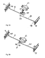
- the state is shown where the actuator 6A is not yet connected to the actuating flap 4A or preassembled, whereas in Fig. 3B the assembled state of the electric motor 6A with the operation flap 4A is shown.
- the electric motor 6A is fixed at a first end 10A of the connecting rod 8A via a first connecting element 9, which is arranged on a lower side of the electric motor 6A.
- the connecting rod 8A has a second end 10B, which in turn is pivotally connected to the actuating flap 4A.
- the actuating flap 4A can be opened or closed or adjusted according to a rotation angle of the Aktuatros 6A, to regulate the air supply of a partial air flow for defrosting a windshield
- Fig. 4A is a perspective view of other components of the air distribution system; and Fig. 4B is a perspective view of the components of the air distribution system of Fig. 4A ,
- the second actuator 6B is shown, which can be connected via the connecting rod 8D to the actuating flap 4D for regulating a partial air flow for right-side ventilation of the motor vehicle and via the connecting rod 8E with the actuating flap 4E for regulating a partial air flow to the left-side ventilation of the motor vehicle.
- the unconnected state is again shown.
- Fig. 4A the unconnected state is again shown.
- FIG. 4B shows the assembled state in which the first end 11A of the connecting rod 8D and the first end 12A of the connecting rod 8E are connected in common to the second actuator 6B via a second connecting member 16.
- the second end 11B of the connecting rod 8D is pivotally connected to the operating flap 4D and the second end 12B of the connecting rod 8E is operatively connected to the operating flap 4E so that the operating flaps 4D and 4E are respectively operable in accordance with a rotational angle of the actuator 6B To regulate partial air flow to the left and right side ventilation of the motor vehicle or to open or close the corresponding opening 3D and 3E in the housing 2.
- Fig. 5A is a perspective view of other components of the air distribution system; and Fig. 5B is a perspective view of Components of the air distribution system of Fig. 5A ,
- the third actuator 6C is shown, which is assigned via the connecting rod 8B to the actuating flap 4B for regulating a partial air flow of the right footwell of the motor vehicle and is assigned via the connecting rod 8C with the actuating flap 4C for regulating a partial air flow of the left footwell of the motor vehicle , connectable.
- the unconnected state is again shown.
- Fig. 5A the unconnected state is again shown.
- FIG. 5B shows the assembled state in which the respective first end 13A of the connecting rod 8B and the first end 14A of the connecting rod 8C are connected together via a third connecting member 15 with the third actuator 6C.
- the second end 13B of the connecting rod 8B is pivotally connected to the operating flap 4B
- the second end 14B of the connecting rod 8C is pivotally connected to the operating flap 4C, so that the operating flaps 4C and 4B are respectively operable in accordance with a rotational angle of the actuator 6C to supply air with a partial air flow to regulate the left and right foot space of the motor vehicle or to open or close the corresponding opening 3C and 3B in the housing 2.
- a pre-assembled assembly can be provided by the central air distribution system 1, on the one hand, and on the other hand a better serviceability can be achieved.
Landscapes
- Physics & Mathematics (AREA)
- Thermal Sciences (AREA)
- Engineering & Computer Science (AREA)
- Mechanical Engineering (AREA)
- Air-Conditioning For Vehicles (AREA)
- Fluid-Pressure Circuits (AREA)
Abstract
Description
- Die Erfindung betrifft eine Klimaanlage, insbesondere für ein Kraftfahrzeug, gemäß dem Oberbegriff des Anspruchs 1.
- Klimaanlagen werden in Kraftfahrzeugen eingesetzt, um den Fahrzeuginnenraum auf eine für die Fahrzeuginsassen angenehme Temperatur zu bringen bzw. diese zu halten. Nach den jeweiligen Erfordernissen kann die Kraftfahrzeugklimaanlage dabei wirken, um die Luft in dem Kraftfahrzeuginnenraum zu erwärmen und/oder zu kühlen.
- Die Luft- und Temperaturverteilung bzw. -regelung bezüglich des Frontbereichs und des Fondbereichs sowie des der rechten Seite und der linken Seite des Fahrzeuginnenraums kann dabei getrennt für jeden einzelnen Bereich oder für mehrere Bereiche gemeinsam ausgeführt werden. Ein Hauptluftstrom wird in mehrere Teilluftströme geleitet, wobei die Teilluftströme den verschiedenen Bereichen des Fahrzeuginnenraums zugeführt werden. Die Regelung der Durchflussmenge der einzelnen Teilluftströme erfolgt dabei über jeweilige Betätigungsklappen, die in der Klimaanlage an entsprechenden Positionen angeordnet sind. Zumindest eine Betätigungsklappe wird durch einen elektromotorischen Aktuator betätigt, um die Luftzufuhr zu einem Bereich des Fahrzeuginnenraums zu steuern. Im Stand der Technik bekannte Klimaanlagen verwenden dabei eine Kinematik, die über verschiedene Gehäuse verteilt ist.
- Bei einem Kinematikverlauf über verschiedene Trennebenen ist die Wartung jedoch beispielsweise im Servicefall problematisch, da eine Zugänglichkeit der Bauteile der Klimaanlage von oben (in der Z-Richtung) nicht möglich ist. Somit ist im Servicefall eine einfache Montage und Demontage nicht gegeben. Vielmehr muss die gesamte Klimaanlage ausgetauscht bzw. ausgebaut werden. Auch ist es bei der im Stand der Technik bekannten getrennten Bauweise von Nachteil, dass es nicht möglich ist, die über verschiedene Gehäuse verteilte Kinematik des Luftverteilungssystems, d. h. die die verschiedenen Betätigungsklappen steuernden Aktuatoren, als Vormontagegruppe bereitzustellen.
- Daher ist es die Aufgabe der vorliegenden Erfindung, eine Klimaanlage, insbesondere für ein Kraftfahrzeug, zur Verfügung zu stellen, bei welcher die Kinematik beispielsweise zu Wartungszwecken leicht für den Monteur zugänglich ist, und wobei im Servicefall kein Austausch der gesamten Klimaanlage erforderlich ist.
- Diese Aufgabe der vorliegenden Erfindung wird durch eine Klimaanlage mit den Merkmalen gemäß Anspruch 1 gelöst. Vorteilhafte Weiterbildungen der vorliegenden Erfindung sind in den Unteransprüchen definiert.
- Erfindungsgemäß wird eine Klimaanlage, insbesondere für ein Kraftfahrzeug, vorgesehen, welche ein Luftverteilungssystem umfasst, welches eine Kinematik mit einer Vielzahl von Aktuatoren aufweist, welche eine Vielzahl von Betätigungsklappen zum Regeln eines Luftstroms in verschiedenen Bereichen eines Kraftfahrzeugs betätigen. Erfindungsgemäß ist die Kinematik zentral in einem einzigen Gehäuse angeordnet. Die zentrale Luftverteilung gemäß der Erfindung, welche in einem einzigen Gehäuse angeordnet ist, macht einerseits die Bereitstellung des Luftverteilungssystems als vormontierte Baugruppe möglich, und andererseits wird ein Kinematikverlauf über verschiedenen Trennebenen vermieden, wodurch eine erhöhte Wartungsfreundlichkeit erzielt wird. Insbesondere ist erfindungsgemäß im Servicefall nicht der Austausch der gesamten Klimaanlage, sondern lediglich der Kinematik, bzw. des Luftverteilungssystems erforderlich. Auch wird durch diese Konfiguration Im Servicefall eine einfache Montage und Demontage ermöglicht.
- Gemäß einer bevorzugten Ausführungsform ist jeder Aktuator mit zumindest einer Betätigungsklappe über eine jeweilige Verbindungsstange verbunden. Vorzugsweise ist die Verbindungsstange an einem ersten Ende gelenkig mit einem Aktuator, insbesondere über ein Verbindungselement, verbunden und an einem zweiten Ende ist sie gelenkig mit einer Betätigungsklappe verbunden. Wenn ein Aktuator dazu verwendet wird, zwei Betätigungsklappen zu betätigen, werden zwei Verbindungsstangen, jeweils eine für jede Betätigungsklappe, eingesetzt. Alternativ ist jedoch auch möglich für zwei Betätigungsklappen, die synchron zu steuern sind, eine einzige Verbindungsstange vorzusehen, welche mit einem ersten Ende gelenkig mit dem Aktuator verbunden ist, und welche dann verzweigt ausgeführt ist, um zwei zweite Enden aufzuweisen, wovon jeweils eines einer Betätigungsklappe, beispielsweise zur Belüftung, zugeordnet ist.
- Gemäß noch einer bevorzugten Ausführungsform ist die Kinematik, insbesondere das Luftverteilungssystem, als Vormontagegruppe hergestellt.
- Vorzugsweise sind die Aktuatoren Elektromotoren. Besonders bevorzugt sind die Aktuatoren Schrittmotoren, die über eine Steuerelektronik ansteuerbar sind.
- Es ist darüber hinaus besonders bevorzugt, wenn die Kinematik drei Aktuatoren, insbesondere Schrittmotoren umfasst.
- Gemäß noch einer weiteren bevorzugten Ausführungsform sind in dem Luftverteilungssystem fünf Betätigungsklappen vorgesehen, welche durch die drei Aktuatoren betätigt werden. In der bevorzugten Ausführungsform sind vier der fünf Betätigungsklappen paarweise jeweils einem Aktuator zugeordnet und eine weitere Betätigungsklappe ist einzeln mit einem weiteren Aktuator verbunden. Es ist jedoch auch jegliche andere Konfiguration mit einer beliebigen Anzahl von Aktuatoren, die eine beliebige Anzahl von Betätigungsklappen steuern, möglich, solange dies zentral geschieht. Die Aktuatoren sind besonders bevorzugt als Schrittmotoren ausgebildet.
- Gemäß einer weiteren bevorzugten Ausführungsform betätigt ein erster Aktuator eine Betätigungsklappe zum Entfrosten der Windschutzscheibe.
- Vorzugsweise betätigt ein zweiter Aktuator eine Betätigungsklappe zur linksseitigen Belüftung des Kraftfahrzeugs sowie eine Betätigungsklappe zur rechtsseitigen Belüftung des Kraftfahrzeugs.
- Darüber hinaus betätigt gemäß noch einer weiteren Ausführungsform ein dritter Aktuator eine Betätigungsklappe, die dem linken Fußraum des Fahrzeugs zugeordnet ist, sowie eine Betätigungsklappe, die dem rechten Fußraum des Fahrzeugs zugeordnet ist.
- Besonders bevorzugt ist es bei der zentralen Luftverteilung, dass die Aktuatoren nebeneinander bzw. benachbart zueinander angeordnet sind.
- Gemäß einer weiteren bevorzugten Ausführungsform sind die Betätigungsklappen ebenfalls in dem Gehäuse angeordnet.
- Vorzugsweise ist jeder Betätigungsklappe eine erste Luftaustrittsöffnung in dem Gehäuse zugewiesen. Gemäß einer bevorzugten Ausführungsform sind somit fünf erste Luftaustrittsöffnungen in dem Gehäuse vorgesehen.
- Darüber hinaus ist gemäß noch einer weiteren bevorzugten Ausführungsform in dem Gehäuse an der Position der Aktuatoren eine zweite Öffnung vorgesehen. Vorzugsweise ist das Gehäuse derartig ausgestaltet, dass in der zweiten Öffnung die Aktuatoren von einer Gehäusewand umgeben sind, d. h. die Aktuatoren sind in dem Gehäuse eingelassen.
- Noch bevorzugter umfasst die Kinematik weiterhin eine Steuerelektronik zur Ansteuerung der Aktuatoren. Die Steuerelektronik eines jeden Aktuators kann an den Aktuatoren angeordnet sein und über einen Signalbus mit einem Hauptsteuergerät verbunden sein.
- Gemäß einer weiteren bevorzugten Ausführungsform umfasst die Klimaanlage weiterhin einen Verdampfer zum Kühlen des Luftstroms und/oder zumindest eine Heizeinrichtung zum Erwärmen des Luftstroms und/oder einen elektrischen Zuheizer und/oder ein Gebläse.
- Im Folgenden wird die Erfindung anhand eines Ausführungsbeispiels unter Bezugnahme auf die Zeichnung detailliert erläutert. In der Zeichnung zeigen:
- Fig.1A
- eine perspektivische Ansicht eines Luftverteilungssystems von oben;
- Fig. 1B
- eine perspektivische Ansicht des Luftverteilungssystems von
Fig. 1A von unten; - Fig. 2A
- eine perspektivische Ansicht des Luftverteilungssystems von
Fig. 1A ohne Gehäuse von oben; - Fig. 2B
- eine perspektivische Ansicht des Luftverteilungssystems von
Fig. 1A ohne Gehäuse von unten; - Fig. 3A
- eine perspektivische Ansicht von Komponenten des Luftverteilungs-systems;
- Fig. 3B
- eine perspektivische Ansicht der Komponenten des Luftverteilungs-systems von
Fig. 3A ; - Fig. 4A
- eine perspektivische Ansicht von weiteren Komponenten des Luft-verteilungssystems;
- Fig. 4B
- eine perspektivische Ansicht der Komponenten des Luftverteilungs-systems von
Fig. 4A ; - Fig. 5A
- eine perspektivische Ansicht von weiteren Komponenten des Luft-verteilungssystems;
- Fig. 5B
- eine perspektivische Ansicht der Komponenten des Luftverteilungs-systems von
Fig. 5A . - In
Fig. 1A ist eine perspektivische Gesamtansicht eines Luftverteilersystems 1 gemäß einer Ausführungsform der Erfindung von oben gezeigt, währendFig. 1B das Luftverteilersystem 1 vonFig. 1A von unten zeigt. Das Luftverteilersystem 1 umfasst ein einziges Gehäuse 2, in welchem die einzelnen Komponenten des Luftverteilersystems 1 angeordnet sind. In dieser Ausführungsform weist das Gehäuse 2 fünf erste Luftaustrittsöffnungen 3A, 3B, 3C, 3D, 3E auf, durch welche die Zufuhr von Teilluftströmen eines Hauptluftstroms, welche zu verschiednen Bereichen eines Fahrzeuginnenraums geleitet werden, geregelt wird. Hier ist die Luftaustrittsöffnung 3A einem Teilluftstrom zur Entfrostung der Windschutzscheibe des Kraftfahrzeugs zugewiesen, die Luftaustrittsöffnung 3B ist einem Teilluftstrom zum rechten Fußraum zugewiesen, die Luftaustrittsöffnung 3C ist einem Teilluftstrom zum linken Fußraum zugewiesen, die Luftaustrittsöffnung 3D ist einem Teilluftstrom zur Belüftung der rechten Seite des Kraftfahrzeugs zugewiesen, und schließlich ist die Luftaustrittsöffnung 3E einem Teilluftstrom zur Belüftung der linken Seite des Kraftfahrzeugs zugeordnet Die Luftaustrittsöffnungen 3A, 3B, 3C, 3D, 3E sind in dem Gehäuse 2 derartig angeordnet, dass sie durch eine jeweilige Betätigungsklappe 4A, 4B, 4C, 4D, 4E des Luftverteilungssystems 1 verschließbar sind. Das heißt, dass die Positionen der jeweiligen Luftaustrittsöffnungen 3A, 3B, 3C, 3D, 3E an dem Gehäuse 2 jeweils den Positionen der Betätigungsklappen 4A, 4B, 4C, 4D, 4E entsprechend angeordnet sind. - Das Gehäuse 2 weist darüber hinaus eine zweite Öffnung 5 auf, in welcher eine zentrale Kinematik des Luftverteilungssystems 1, welche hier aus drei Aktuatoren 6 in Form von Schrittmotoren besteht, angeordnet ist. Die Aktuatoren 6 bzw. Schrittmotoren sind dabei von einer Wand 7 des Gehäuses 2 umgeben, so dass sie in der Öffnung 5 in dem Gehäuse 2 eingelassen sind, was einen Schutz der Aktuatoren 6 vorsieht.
- Wie in
Fig. 1B erkannt werden kann, sind die Aktuatoren 6 über jeweilige Verbindungsstangen 8A, 8B, 8C, 8D, 8E mit den jeweiligen Betätigungsklappen 4A, 4B, 4C, 4D, 4E gelenkig verbunden. Bei entsprechender Steuerung eines oder mehrere der Aktuatoren 6 kann über eine entsprechende Verbindungsstange 8A, 8B, 8C, 8D, 8E die damit verbundene Betätigungsklappe 4A, 4B, 4C, 4D, 4E bewegt bzw. gedreht werden, so dass eine der Betätigungsklappe 4A, 4B, 4C, 4D, 4E zugeordnete Luftaustrittsöffnung 3A, 3B, 3C, 3D, 3E geöffnet oder geschlossen wird. Weiterhin kann inFig. 1B gesehen werden, dass das Gehäuse 2 ein nach unten geöffnetes Gehäuse ist, das keinen Gehäuseboden aufweist. -
Fig. 2A zeigt eine perspektivische Ansicht des Luftverteilungssystems 1 vonFig. 1A ohne Gehäuse 2 von oben, wohingegenFig. 2B eine perspektivische Ansicht des Luftverteilungssystems 1 vonFig. 1A ohne Gehäuse 2 von unten zeigt. Wie in beiden Figuren erkannt werden kann, sind die drei Aktuatoren 6A, 6B, 6C nebeneinander in einer Reihe zentral zwischen den Betätigungsklappen 4A, 4B, 4C, 4D, 4E angeordnet. Der erste Aktuator 6A ist zwischen dem zweiten Aktuator 6B und dem dritten Aktuator 6C angeordnet und ist über eine Verbindungsstange 8A mit der Betätigungsklappe 4A für einen Teilluftstrom zum Entfrosten der Windschutzscheibe eines Kraftfahrzeugs gelenkig verbunden. Weiterhin ist der zweite Aktuator 6B einerseits über eine Verbindungsstange 8B mit einer Betätigungsklappe 4B, welche hier für die Regelung des Teilluftstrorns zum rechten Fußraum vorgesehen ist, und andererseits über eine weitere Verbindungsstange 8C mit einer Betätigungsklappe 4C, welche hier für die Regelung des Teilluftstroms zum linken Fußraum des Kraftfahrzeugs vorgesehen ist, verbunden, Schließlich ist der dritte Aktuator 6C über eine Verbindungsstange 8D mit einer Betätigungsklappe 4D, welche hier für die Regelung des Teilluftstroms zur rechtsseitigen Belüftung des Kraftfahrzeugs vorgesehen ist, und über eine weitere Verbindungsstange 8E mit einer Betätigungsklappe 4E verbunden, welche hier für die Regelung des Teilluftstroms zur linksseitigen Belüftung des Kraftfahrzeugs vorgesehen ist. -
Fig. 3A ist eine perspektivische Ansicht von einzelnen Komponenten des Luftverteilungssystems 1; undFig. 3B ist eine perspektivische Ansicht der Komponenten des Luftverteilungssystems vonFig. 3A . Hier die Betätigungsklappe 4A zur Regelung des Teilluftstroms zum Entfrosten der Windschutzscheibe dargestellt. Die Betätigungsklappe 4A ist über die Verbindungsstange 8A mit dem Aktuator 6A gelenkig verbindbar. InFig. 3A ist jedoch der Zustand gezeigt, wo der Aktuator 6A noch nicht mit der Betätigungsklappe 4A verbunden bzw. vormontiert ist, wohingegen inFig. 3B der zusammengesetzte bzw. montierte Zustand des Elektromotors 6A mit der Betätigungsklappe 4A gezeigt ist. Dabei wird der Elektromotor 6A über ein erstes Verbindungselement 9, welches an einer Unterseite des Elektromotors 6A angeordnet ist, an einem ersten Ende 10A der Verbindungsstange 8A fixiert. Die Verbindungsstange 8A weist ein zweites Ende 10B auf, welches wiederum gelenkig mit der Betätigungsklappe 4A verbunden ist. Über diese Verbindung lässt sich die Betätigungsklappe 4A entsprechend einem Drehwinkel des Aktuatros 6A öffnen oder schließen bzw. verstellen, um die Luftzufuhr eines Teilluftstrom zum Entfrosten einer windschutzscheibe zu regeln -
Fig. 4A ist eine perspektivische Ansicht von weiteren Komponenten des Luftverteilungssystems; undFig. 4B ist eine perspektivische Ansicht der Komponenten des Luftverteilungssystems vonFig. 4A . Hier ist der zweite Aktuator 6B gezeigt, welcher über die Verbindungsstange 8D mit der Betätigungsklappe 4D zum Regeln eines Teilluftstroms zur rechtsseitigen Belüftung des Kraftfahrzeugs und über die Verbindungsstange 8E mit der Betätigungsklappe 4E zum Regeln eines Teilluftstroms zur linksseitigen Belüftung des Kraftfahrzeugs verbindbar. InFig. 4A ist jedoch wieder der noch nicht verbundene Zustand gezeigt.Fig. 4B zeigt dagegen den montierten Zustand, in welchem das erste Ende 11A der Verbindungsstange 8D und das erste Ende 12A der Verbindungsstange 8E gemeinsam über ein zweites Verbindungselement 16 mit dem zweiten Aktuator 6B verbunden sind. Das zweite Ende 11 B der Verbindungsstange 8D ist mit der Betätigungsklappe 4D und das zweite Ende 12B der Verbindungsstange 8E ist mit der Betätigungsklappe 4E gelenkig verbunden, so dass die Betätigungsklappen 4D und 4E jeweils entsprechend einem Drehwinkel des Aktuators 6B betätigbar sind, um eine Luftzufuhr eines Teilluftstrom zur links- und rechtsseitigen Belüftung des Kraftfahrzeugs zu regeln bzw. die entsprechende Öffnung 3D und 3E in dem Gehäuse 2 zu öffnen oder zu schließen. -
Fig. 5A ist eine perspektivische Ansicht von weiteren Komponenten des Luftverteilungssystems; undFig. 5B ist eine perspektivische Ansicht der Komponenten des Luftverteilungssystems vonFig. 5A . Hier ist der dritte Aktuator 6C gezeigt, welcher über die Verbindungsstange 8B mit der Betätigungsklappe 4B zum Regeln eines Teilluftstroms der dem rechten Fußraum des Kraftfahrzeugs zugeordnet ist und über die Verbindungsstange 8C mit der Betätigungsklappe 4C zum Regeln eines Teilluftstroms der dem linken Fußraum des Kraftfahrzeugs zugeordnet ist, verbindbar. InFig. 5A ist jedoch wieder der noch nicht verbundene Zustand gezeigt.Fig. 5B zeigt den montierten Zustand, in welchem das jeweilige erste Ende 13A der Verbindungsstange 8B und das erste Ende 14A der Verbindungsstange 8C gemeinsam über ein drittes Verbindungselement 15 mit dem dritten Aktuator 6C verbunden sind. Das zweite Ende 13B der Verbindungsstange 8B ist mit der Betätigungsklappe 4B und das zweite Ende 14B der Verbindungsstange 8C ist mit der Betätigungsklappe 4C gelenkig verbunden, so dass die Betätigungsklappen 4C und 4B jeweils entsprechend einem Drehwinkel des Aktuators 6C betätigbar sind, um eine Luftzufuhr eines Teilluftstrom zum linken und rechten Fußraum des Kraftfahrzeugs zu regeln bzw. die entsprechende Öffnung 3C und 3B in dem Gehäuse 2 zu öffnen oder zu schließen. - Insgesamt betrachtet kann durch das zentrale Luftverteilungssystem 1 einerseits eine vormontierte Baugruppe bereitgestellt werden, und andererseits eine bessere Wartungsfreundlichkeit erzielt werden.
-
- 1
- Luftverteilungssystem
- 2
- Gehäuse
- 3A, 3B, 3C, 3D
- erste Luftaustrittsöffnungen
- 4A, 4B, 4C, 4D
- Betätigungsklappen
- 5
- zweite Öffnung
- 6A
- erster Aktuator
- 6B
- zweiter Aktuator
- 6C
- dritter Aktuator
- 7
- Wand
- 8A, 8B, 8C, 8D
- Verbindungsstangen
- 9
- erstes Verbindungselement
- 10A
- erstes Ende der Verbindungsstange 8A
- 10B
- zweites Ende der Verbindungsstange 8A
- 12A
- erstes Ende der Verbindungsstange 8E
- 12B
- zweites Ende der Verbindungsstange 8E
- 13A
- erstes Ende der Verbindungsstange 8B
- 13B
- zweites Ende der Verbindungsstange 8B
- 14A
- erstes Ende der Verbindungsstange 8C
- 14B
- zweites Ende der Verbindungsstange 8C
- 15
- drittes Verbindungselement
- 16
- zweites Verbindungselement
Claims (15)
- Klimaanlage, insbesondere für ein Kraftfahrzeug, welche ein Luftverteilungssystem (1) umfasst, welches eine Kinematik mit einer Vielzahl von Aktuatoren (6A, 6B, 6C) aufweist, welche eine Vielzahl von Betätigungsklappen (4A, 4B, 4C, 4D, 4E) zum Regeln eines Luftstroms in verschiedenen Bereichen eines Kraftfahrzeugs betätigen, dadurch gekennzeichnet, dass die Kinematik zentral in einem einzigen Gehäuse (2) angeordnet ist.
- Klimaanlage nach Anspruch 1, dadurch gekennzeichnet dass jeder Aktuator (6A, 6B, 6C) mit zumindest einer Betätigungsklappe (4A, 4B, 4C, 4D, 4E) über eine jeweilige Verbindungsstange (8A, 8B, 8C, 8D, 8E) verbunden ist.
- Klimaanlage nach Anspruch 1 oder 2, dadurch gekennzeichnet, dass die Kinematik, insbesondere das Luftverteilungssystem (1), als Vormontagegruppe hergestellt ist.
- Klimaanlage nach einem oder mehreren der Ansprüche 1 bis 3, dadurch gekennzeichnet, dass die Aktuatoren (6A, 6B, 6C) Elektromotoren, insbesondere Schrittmotoren sind.
- Kraftfahrzeugklimaanlage nach Anspruch 4, dadurch gekennzeichnet, dass die Kinematik drei Schrittmotoren (6A, 6B, 6C) umfasst.
- Kraftfahrzeugklimaanlage nach Anspruch 4 oder 5, dadurch gekennzeichnet, dass in dem Luftverteilungssystem (1) fünf Betätigungsklappen (4A, 4B, 4C, 4D, 4E) vorgesehen sind, welche durch die drei Schrittmotoren (6A, 6B, 6C) betätigt werden.
- Kraftfahrzeugklimaanlage nach einem oder mehreren der Ansprüche 1 bis 6, dadurch gekennzeichnet dass ein erster Aktuator (6A) eine Betätigungsklappe (4A) zum Entfrosten einer Windschutzscheibe betätigt.
- Kraftfahrzeugklimaanlage nach einem oder mehreren der Ansprüche 1 bis 7, dadurch gekennzeichnet dass ein zweiter Aktuator (6B) jeweils eine Betätigungsklappe (4E) zur linksseitigen Belüftung des Kraftfahrzeugs sowie eine Betätigungsklappe (4D) zur rechtsseitigen Belüftung des Kraftfahrzeugs betätigt.
- Kraftfahrzeugklimaanlage nach einem oder mehreren der Ansprüche 1 bis 8, dadurch gekennzeichnet, dass ein dritter Aktuator (6C) jeweils eine Betätigungsklappe (4C) betätigt, die dem linken Fußraum des Fahrzeugs zugeordnet ist, sowie eine Betätigungsklappe (4B), die dem rechten Fußraum des Fahrzeugs zugeordnet ist.
- Kraftfahrzeugklimaanlage nach einem oder mehreren der Ansprüche 1 bis 9, dadurch gekennzeichnet, dass die Aktuatoren (6A, 6B, 6C) nebeneinander angeordnet sind.
- Kraftfahrzeugklimaanlage nach einem oder mehreren der Ansprüche 1 bis 10, dadurch gekennzeichnet, dass die Betätigungsklappen (4A, 4B, 4C, 4D, 4E) ebenfalls in dem Gehäuse (2) angeordnet sind.
- Kraftfahrzeugklimaanlage nach einem oder mehreren der Ansprüche 1 bis 11, dadurch gekennzeichnet, dass jeder Betätigungsklappe (4A, 4B, 4C, 4D, 4E) eine erste Luftaustrittsöffnung (3A, 3B, 3C, 3D, 3E) in dem Gehäuse (2) zugeordnet ist.
- Kraftfahrzeugklimaanlage nach einem oder mehreren der Ansprüche 1 bis 12, dadurch gekennzeichnet dass in dem Gehäuse (2) an der Position der Aktuatoren eine zweite Öffnung (5) vorgesehen ist.
- Kraftfahrzeugklimaanlage nach einem oder mehreren der Ansprüche 1 bis 13, dadurch gekennzeichnet, dass die Kinematik weiterhin eine Steuerelektronik zur Ansteuerung der Aktuatoren (6A, 6B, 6C) umfasst.
- Kraftfahrzeugklimaanlage nach einem der Ansprüche 1 bis 14, dadurch gekennzeichnet dass die Kraftfahrzeugklimaanlage weiterhin einen Verdampfer zum Kühlen des Luftstroms und/oder zumindest eine Heizeinrichtung zum Erwärmen des Luftstroms und/oder einen elektrischen Zuheizer und/oder ein Gebläse umfasst.
Applications Claiming Priority (1)
| Application Number | Priority Date | Filing Date | Title |
|---|---|---|---|
| DE102008048990A DE102008048990A1 (de) | 2008-09-25 | 2008-09-25 | Klimaanlage |
Publications (2)
| Publication Number | Publication Date |
|---|---|
| EP2168793A1 true EP2168793A1 (de) | 2010-03-31 |
| EP2168793B1 EP2168793B1 (de) | 2011-08-10 |
Family
ID=41351864
Family Applications (1)
| Application Number | Title | Priority Date | Filing Date |
|---|---|---|---|
| EP09012148A Not-in-force EP2168793B1 (de) | 2008-09-25 | 2009-09-24 | Klimaanlage |
Country Status (3)
| Country | Link |
|---|---|
| EP (1) | EP2168793B1 (de) |
| AT (1) | ATE519616T1 (de) |
| DE (1) | DE102008048990A1 (de) |
Cited By (1)
| Publication number | Priority date | Publication date | Assignee | Title |
|---|---|---|---|---|
| WO2015071340A1 (en) * | 2013-11-15 | 2015-05-21 | Valeo Klimasysteme Gmbh | Control device for controlling at least two air distribution flaps of a heating and/or air-conditioning unit of a motor vehicle |
Citations (3)
| Publication number | Priority date | Publication date | Assignee | Title |
|---|---|---|---|---|
| DE19524068A1 (de) * | 1995-07-01 | 1997-01-02 | Behr Gmbh & Co | Aktuatoranordnung und diese verwendende Vorrichtung |
| EP1671823A2 (de) * | 2004-12-20 | 2006-06-21 | Behr GmbH & Co. KG | Gehäuse für ein Kraftfahrzeug-Belüftungssystem |
| EP1872985A1 (de) * | 2006-06-29 | 2008-01-02 | Delphi Technologies, Inc. | Verstellsystem mit integriertem Warmluftauslass |
Family Cites Families (4)
| Publication number | Priority date | Publication date | Assignee | Title |
|---|---|---|---|---|
| DE19643233A1 (de) * | 1996-10-19 | 1998-04-23 | Hossein Soltanmoradi | Vorrichtung zur Ansteuerung von wenigstens zwei Stellorganen |
| DE10127347A1 (de) * | 2001-06-06 | 2002-12-12 | Valeo Klimasysteme Gmbh | Vorrichtung zur Steuerung des Öffnungswinkels von Lüfterklappen einer Fahrzeugbelüftungs-/-klimaanlage |
| JP2004330961A (ja) * | 2003-05-09 | 2004-11-25 | Denso Corp | 車両用空調装置 |
| FR2872931B1 (fr) * | 2004-07-07 | 2006-08-18 | Valeo Climatisation Sa | Mecanisme de commande d'un organe a manoeuvrer, tel que distribution selective d'air pour installation de chauffage, de ventilation et/ou de climatisation, notamment d'un habitacle de vehicule |
-
2008
- 2008-09-25 DE DE102008048990A patent/DE102008048990A1/de not_active Withdrawn
-
2009
- 2009-09-24 AT AT09012148T patent/ATE519616T1/de active
- 2009-09-24 EP EP09012148A patent/EP2168793B1/de not_active Not-in-force
Patent Citations (3)
| Publication number | Priority date | Publication date | Assignee | Title |
|---|---|---|---|---|
| DE19524068A1 (de) * | 1995-07-01 | 1997-01-02 | Behr Gmbh & Co | Aktuatoranordnung und diese verwendende Vorrichtung |
| EP1671823A2 (de) * | 2004-12-20 | 2006-06-21 | Behr GmbH & Co. KG | Gehäuse für ein Kraftfahrzeug-Belüftungssystem |
| EP1872985A1 (de) * | 2006-06-29 | 2008-01-02 | Delphi Technologies, Inc. | Verstellsystem mit integriertem Warmluftauslass |
Cited By (3)
| Publication number | Priority date | Publication date | Assignee | Title |
|---|---|---|---|---|
| WO2015071340A1 (en) * | 2013-11-15 | 2015-05-21 | Valeo Klimasysteme Gmbh | Control device for controlling at least two air distribution flaps of a heating and/or air-conditioning unit of a motor vehicle |
| CN105899385A (zh) * | 2013-11-15 | 2016-08-24 | 法雷奥空调系统有限责任公司 | 用于控制机动车辆的加热和/或空气调节单元的至少两个空气分配挡板的控制装置 |
| JP2016537250A (ja) * | 2013-11-15 | 2016-12-01 | ヴァレオ クリマジステーメ ゲーエムベーハー | 自動車の加熱及び/又は空調ユニットの少なくとも2つの空気分配フラップを制御するための制御装置 |
Also Published As
| Publication number | Publication date |
|---|---|
| EP2168793B1 (de) | 2011-08-10 |
| ATE519616T1 (de) | 2011-08-15 |
| DE102008048990A1 (de) | 2010-04-01 |
Similar Documents
| Publication | Publication Date | Title |
|---|---|---|
| DE102004033402B4 (de) | Modulsystem zum Aufbau einer 1-Zonen-bis 4-Zonen-Klimaanlage für Fahrzeuge | |
| EP1761406B1 (de) | Klimaanlage, insbesondere kraftfahrzeug-klimaanlage | |
| DE102019220154A1 (de) | Klimaanlage | |
| EP1634735B1 (de) | Modulare Kraftfahrzeugklimaanlage | |
| EP1306241B1 (de) | Fahrzeugheiz- und Klimaanlage mit kombinierter Luftmisch- und -verteilklappe | |
| DE102012012654A1 (de) | Fahrzeugheizungs-, -lüftungs- und/oder -klimaanlage | |
| DE112011101965B4 (de) | Fahrzeug-Klimaanlage | |
| DE102014210264A1 (de) | Klimaanlage und Verfahren zur Lufttemperierung | |
| EP2168793B1 (de) | Klimaanlage | |
| EP0752333A2 (de) | Aktuatoranordnung und diese verwendende Vorrichtung | |
| EP1761405B1 (de) | Klimaanlage, insbesondere kraftfahrzeug-klimaanlage | |
| DE102005029774A1 (de) | Klimaanlage, insbesondere Kraftfahrzeug-Klimaanlage | |
| EP1792760B1 (de) | Klimaanlage, insbesondere für ein Kraftfahrzeug | |
| DE102005029773A1 (de) | Klimaanlage, insbesondere Kraftfahrzeug-Klimaanlage | |
| EP2088011B1 (de) | Gehäuse-Anordnung für eine Fahrzeugklimaanlage | |
| WO2001040002A1 (de) | Heiz- und/oder klimaanlage für ein fahrzeug mit teilluftführungskanal | |
| DE10320750A1 (de) | Klimaanlage | |
| EP1531067B1 (de) | Klimatisierungsvorrichtung, insbesondere für ein Kraftfahrzeug | |
| EP2353896B1 (de) | Klimaanlage | |
| DE102009032599A1 (de) | Klimamodul für ein Kraftfahrzeug | |
| EP1641641B1 (de) | Belüftungsvorrichtung, insbesondere für eine heizung oder klimaanlage eines kraftfahrzeugs | |
| DE102007031251A1 (de) | Klimaanlage | |
| DE102011080214A1 (de) | Heiz- oder Klimaanlage, insbesondere für ein Kraftfahrzeug | |
| EP2133223B1 (de) | Klimaanlage für ein Kraftfahrzeug | |
| EP2311675B1 (de) | Klimaanlage |
Legal Events
| Date | Code | Title | Description |
|---|---|---|---|
| PUAI | Public reference made under article 153(3) epc to a published international application that has entered the european phase |
Free format text: ORIGINAL CODE: 0009012 |
|
| AK | Designated contracting states |
Kind code of ref document: A1 Designated state(s): AT BE BG CH CY CZ DE DK EE ES FI FR GB GR HR HU IE IS IT LI LT LU LV MC MK MT NL NO PL PT RO SE SI SK SM TR |
|
| AX | Request for extension of the european patent |
Extension state: AL BA RS |
|
| 17P | Request for examination filed |
Effective date: 20100930 |
|
| 17Q | First examination report despatched |
Effective date: 20101026 |
|
| GRAP | Despatch of communication of intention to grant a patent |
Free format text: ORIGINAL CODE: EPIDOSNIGR1 |
|
| GRAC | Information related to communication of intention to grant a patent modified |
Free format text: ORIGINAL CODE: EPIDOSCIGR1 |
|
| GRAS | Grant fee paid |
Free format text: ORIGINAL CODE: EPIDOSNIGR3 |
|
| GRAA | (expected) grant |
Free format text: ORIGINAL CODE: 0009210 |
|
| AK | Designated contracting states |
Kind code of ref document: B1 Designated state(s): AT BE BG CH CY CZ DE DK EE ES FI FR GB GR HR HU IE IS IT LI LT LU LV MC MK MT NL NO PL PT RO SE SI SK SM TR |
|
| REG | Reference to a national code |
Ref country code: GB Ref legal event code: FG4D Free format text: NOT ENGLISH |
|
| REG | Reference to a national code |
Ref country code: CH Ref legal event code: EP |
|
| REG | Reference to a national code |
Ref country code: IE Ref legal event code: FG4D Free format text: LANGUAGE OF EP DOCUMENT: GERMAN |
|
| REG | Reference to a national code |
Ref country code: DE Ref legal event code: R096 Ref document number: 502009001072 Country of ref document: DE Effective date: 20111006 |
|
| REG | Reference to a national code |
Ref country code: NL Ref legal event code: VDEP Effective date: 20110810 |
|
| LTIE | Lt: invalidation of european patent or patent extension |
Effective date: 20110810 |
|
| PG25 | Lapsed in a contracting state [announced via postgrant information from national office to epo] |
Ref country code: NL Free format text: LAPSE BECAUSE OF FAILURE TO SUBMIT A TRANSLATION OF THE DESCRIPTION OR TO PAY THE FEE WITHIN THE PRESCRIBED TIME-LIMIT Effective date: 20110810 Ref country code: FI Free format text: LAPSE BECAUSE OF FAILURE TO SUBMIT A TRANSLATION OF THE DESCRIPTION OR TO PAY THE FEE WITHIN THE PRESCRIBED TIME-LIMIT Effective date: 20110810 Ref country code: HR Free format text: LAPSE BECAUSE OF FAILURE TO SUBMIT A TRANSLATION OF THE DESCRIPTION OR TO PAY THE FEE WITHIN THE PRESCRIBED TIME-LIMIT Effective date: 20110810 Ref country code: IS Free format text: LAPSE BECAUSE OF FAILURE TO SUBMIT A TRANSLATION OF THE DESCRIPTION OR TO PAY THE FEE WITHIN THE PRESCRIBED TIME-LIMIT Effective date: 20111210 Ref country code: SE Free format text: LAPSE BECAUSE OF FAILURE TO SUBMIT A TRANSLATION OF THE DESCRIPTION OR TO PAY THE FEE WITHIN THE PRESCRIBED TIME-LIMIT Effective date: 20110810 Ref country code: NO Free format text: LAPSE BECAUSE OF FAILURE TO SUBMIT A TRANSLATION OF THE DESCRIPTION OR TO PAY THE FEE WITHIN THE PRESCRIBED TIME-LIMIT Effective date: 20111110 Ref country code: PT Free format text: LAPSE BECAUSE OF FAILURE TO SUBMIT A TRANSLATION OF THE DESCRIPTION OR TO PAY THE FEE WITHIN THE PRESCRIBED TIME-LIMIT Effective date: 20111212 Ref country code: LT Free format text: LAPSE BECAUSE OF FAILURE TO SUBMIT A TRANSLATION OF THE DESCRIPTION OR TO PAY THE FEE WITHIN THE PRESCRIBED TIME-LIMIT Effective date: 20110810 |
|
| PG25 | Lapsed in a contracting state [announced via postgrant information from national office to epo] |
Ref country code: LV Free format text: LAPSE BECAUSE OF FAILURE TO SUBMIT A TRANSLATION OF THE DESCRIPTION OR TO PAY THE FEE WITHIN THE PRESCRIBED TIME-LIMIT Effective date: 20110810 Ref country code: CY Free format text: LAPSE BECAUSE OF FAILURE TO SUBMIT A TRANSLATION OF THE DESCRIPTION OR TO PAY THE FEE WITHIN THE PRESCRIBED TIME-LIMIT Effective date: 20110810 Ref country code: SI Free format text: LAPSE BECAUSE OF FAILURE TO SUBMIT A TRANSLATION OF THE DESCRIPTION OR TO PAY THE FEE WITHIN THE PRESCRIBED TIME-LIMIT Effective date: 20110810 Ref country code: GR Free format text: LAPSE BECAUSE OF FAILURE TO SUBMIT A TRANSLATION OF THE DESCRIPTION OR TO PAY THE FEE WITHIN THE PRESCRIBED TIME-LIMIT Effective date: 20111111 Ref country code: PL Free format text: LAPSE BECAUSE OF FAILURE TO SUBMIT A TRANSLATION OF THE DESCRIPTION OR TO PAY THE FEE WITHIN THE PRESCRIBED TIME-LIMIT Effective date: 20110810 |
|
| REG | Reference to a national code |
Ref country code: IE Ref legal event code: FD4D |
|
| BERE | Be: lapsed |
Owner name: BEHR G.M.B.H. & CO. KG Effective date: 20110930 |
|
| PG25 | Lapsed in a contracting state [announced via postgrant information from national office to epo] |
Ref country code: IE Free format text: LAPSE BECAUSE OF FAILURE TO SUBMIT A TRANSLATION OF THE DESCRIPTION OR TO PAY THE FEE WITHIN THE PRESCRIBED TIME-LIMIT Effective date: 20110810 Ref country code: MC Free format text: LAPSE BECAUSE OF NON-PAYMENT OF DUE FEES Effective date: 20110930 Ref country code: SK Free format text: LAPSE BECAUSE OF FAILURE TO SUBMIT A TRANSLATION OF THE DESCRIPTION OR TO PAY THE FEE WITHIN THE PRESCRIBED TIME-LIMIT Effective date: 20110810 Ref country code: CZ Free format text: LAPSE BECAUSE OF FAILURE TO SUBMIT A TRANSLATION OF THE DESCRIPTION OR TO PAY THE FEE WITHIN THE PRESCRIBED TIME-LIMIT Effective date: 20110810 |
|
| PG25 | Lapsed in a contracting state [announced via postgrant information from national office to epo] |
Ref country code: IT Free format text: LAPSE BECAUSE OF FAILURE TO SUBMIT A TRANSLATION OF THE DESCRIPTION OR TO PAY THE FEE WITHIN THE PRESCRIBED TIME-LIMIT Effective date: 20110810 Ref country code: EE Free format text: LAPSE BECAUSE OF FAILURE TO SUBMIT A TRANSLATION OF THE DESCRIPTION OR TO PAY THE FEE WITHIN THE PRESCRIBED TIME-LIMIT Effective date: 20110810 Ref country code: RO Free format text: LAPSE BECAUSE OF FAILURE TO SUBMIT A TRANSLATION OF THE DESCRIPTION OR TO PAY THE FEE WITHIN THE PRESCRIBED TIME-LIMIT Effective date: 20110810 |
|
| PLBE | No opposition filed within time limit |
Free format text: ORIGINAL CODE: 0009261 |
|
| STAA | Information on the status of an ep patent application or granted ep patent |
Free format text: STATUS: NO OPPOSITION FILED WITHIN TIME LIMIT |
|
| REG | Reference to a national code |
Ref country code: FR Ref legal event code: ST Effective date: 20120531 |
|
| PG25 | Lapsed in a contracting state [announced via postgrant information from national office to epo] |
Ref country code: BE Free format text: LAPSE BECAUSE OF NON-PAYMENT OF DUE FEES Effective date: 20110930 Ref country code: DK Free format text: LAPSE BECAUSE OF FAILURE TO SUBMIT A TRANSLATION OF THE DESCRIPTION OR TO PAY THE FEE WITHIN THE PRESCRIBED TIME-LIMIT Effective date: 20110810 |
|
| 26N | No opposition filed |
Effective date: 20120511 |
|
| PG25 | Lapsed in a contracting state [announced via postgrant information from national office to epo] |
Ref country code: FR Free format text: LAPSE BECAUSE OF NON-PAYMENT OF DUE FEES Effective date: 20111010 |
|
| REG | Reference to a national code |
Ref country code: DE Ref legal event code: R097 Ref document number: 502009001072 Country of ref document: DE Effective date: 20120511 |
|
| PG25 | Lapsed in a contracting state [announced via postgrant information from national office to epo] |
Ref country code: MT Free format text: LAPSE BECAUSE OF FAILURE TO SUBMIT A TRANSLATION OF THE DESCRIPTION OR TO PAY THE FEE WITHIN THE PRESCRIBED TIME-LIMIT Effective date: 20110810 Ref country code: MK Free format text: LAPSE BECAUSE OF FAILURE TO SUBMIT A TRANSLATION OF THE DESCRIPTION OR TO PAY THE FEE WITHIN THE PRESCRIBED TIME-LIMIT Effective date: 20110810 |
|
| PG25 | Lapsed in a contracting state [announced via postgrant information from national office to epo] |
Ref country code: SM Free format text: LAPSE BECAUSE OF FAILURE TO SUBMIT A TRANSLATION OF THE DESCRIPTION OR TO PAY THE FEE WITHIN THE PRESCRIBED TIME-LIMIT Effective date: 20110810 Ref country code: ES Free format text: LAPSE BECAUSE OF FAILURE TO SUBMIT A TRANSLATION OF THE DESCRIPTION OR TO PAY THE FEE WITHIN THE PRESCRIBED TIME-LIMIT Effective date: 20111121 |
|
| PG25 | Lapsed in a contracting state [announced via postgrant information from national office to epo] |
Ref country code: LU Free format text: LAPSE BECAUSE OF NON-PAYMENT OF DUE FEES Effective date: 20110924 |
|
| PG25 | Lapsed in a contracting state [announced via postgrant information from national office to epo] |
Ref country code: BG Free format text: LAPSE BECAUSE OF FAILURE TO SUBMIT A TRANSLATION OF THE DESCRIPTION OR TO PAY THE FEE WITHIN THE PRESCRIBED TIME-LIMIT Effective date: 20111110 |
|
| PG25 | Lapsed in a contracting state [announced via postgrant information from national office to epo] |
Ref country code: TR Free format text: LAPSE BECAUSE OF FAILURE TO SUBMIT A TRANSLATION OF THE DESCRIPTION OR TO PAY THE FEE WITHIN THE PRESCRIBED TIME-LIMIT Effective date: 20110810 |
|
| PG25 | Lapsed in a contracting state [announced via postgrant information from national office to epo] |
Ref country code: HU Free format text: LAPSE BECAUSE OF FAILURE TO SUBMIT A TRANSLATION OF THE DESCRIPTION OR TO PAY THE FEE WITHIN THE PRESCRIBED TIME-LIMIT Effective date: 20110810 |
|
| REG | Reference to a national code |
Ref country code: CH Ref legal event code: PL |
|
| GBPC | Gb: european patent ceased through non-payment of renewal fee |
Effective date: 20130924 |
|
| PG25 | Lapsed in a contracting state [announced via postgrant information from national office to epo] |
Ref country code: LI Free format text: LAPSE BECAUSE OF NON-PAYMENT OF DUE FEES Effective date: 20130930 Ref country code: GB Free format text: LAPSE BECAUSE OF NON-PAYMENT OF DUE FEES Effective date: 20130924 Ref country code: CH Free format text: LAPSE BECAUSE OF NON-PAYMENT OF DUE FEES Effective date: 20130930 |
|
| REG | Reference to a national code |
Ref country code: DE Ref legal event code: R082 Ref document number: 502009001072 Country of ref document: DE Representative=s name: GRAUEL, ANDREAS, DIPL.-PHYS. DR. RER. NAT., DE |
|
| REG | Reference to a national code |
Ref country code: DE Ref legal event code: R081 Ref document number: 502009001072 Country of ref document: DE Owner name: MAHLE INTERNATIONAL GMBH, DE Free format text: FORMER OWNER: BEHR GMBH & CO. KG, 70469 STUTTGART, DE Effective date: 20110816 Ref country code: DE Ref legal event code: R081 Ref document number: 502009001072 Country of ref document: DE Owner name: MAHLE INTERNATIONAL GMBH, DE Free format text: FORMER OWNER: BEHR GMBH & CO. KG, 70469 STUTTGART, DE Effective date: 20150309 Ref country code: DE Ref legal event code: R082 Ref document number: 502009001072 Country of ref document: DE Representative=s name: GRAUEL, ANDREAS, DIPL.-PHYS. DR. RER. NAT., DE Effective date: 20150309 |
|
| REG | Reference to a national code |
Ref country code: AT Ref legal event code: MM01 Ref document number: 519616 Country of ref document: AT Kind code of ref document: T Effective date: 20140924 |
|
| PG25 | Lapsed in a contracting state [announced via postgrant information from national office to epo] |
Ref country code: AT Free format text: LAPSE BECAUSE OF NON-PAYMENT OF DUE FEES Effective date: 20140924 |
|
| PGFP | Annual fee paid to national office [announced via postgrant information from national office to epo] |
Ref country code: DE Payment date: 20191119 Year of fee payment: 11 |
|
| REG | Reference to a national code |
Ref country code: DE Ref legal event code: R119 Ref document number: 502009001072 Country of ref document: DE |
|
| PG25 | Lapsed in a contracting state [announced via postgrant information from national office to epo] |
Ref country code: DE Free format text: LAPSE BECAUSE OF NON-PAYMENT OF DUE FEES Effective date: 20210401 |