EP2168482B1 - dispositif pour l'extraction d'échantillons liquides - Google Patents
dispositif pour l'extraction d'échantillons liquides Download PDFInfo
- Publication number
- EP2168482B1 EP2168482B1 EP09179103.8A EP09179103A EP2168482B1 EP 2168482 B1 EP2168482 B1 EP 2168482B1 EP 09179103 A EP09179103 A EP 09179103A EP 2168482 B1 EP2168482 B1 EP 2168482B1
- Authority
- EP
- European Patent Office
- Prior art keywords
- movement
- lancet
- sample
- test
- coupling element
- Prior art date
- Legal status (The legal status is an assumption and is not a legal conclusion. Google has not performed a legal analysis and makes no representation as to the accuracy of the status listed.)
- Not-in-force
Links
Images


Classifications
-
- A—HUMAN NECESSITIES
- A61—MEDICAL OR VETERINARY SCIENCE; HYGIENE
- A61B—DIAGNOSIS; SURGERY; IDENTIFICATION
- A61B5/00—Measuring for diagnostic purposes; Identification of persons
- A61B5/14—Devices for taking samples of blood ; Measuring characteristics of blood in vivo, e.g. gas concentration within the blood, pH-value of blood
- A61B5/1405—Devices for taking blood samples
- A61B5/1411—Devices for taking blood samples by percutaneous method, e.g. by lancet
-
- A—HUMAN NECESSITIES
- A61—MEDICAL OR VETERINARY SCIENCE; HYGIENE
- A61B—DIAGNOSIS; SURGERY; IDENTIFICATION
- A61B5/00—Measuring for diagnostic purposes; Identification of persons
- A61B5/145—Measuring characteristics of blood in vivo, e.g. gas concentration, pH value; Measuring characteristics of body fluids or tissues, e.g. interstitial fluid, cerebral tissue
- A61B5/14532—Measuring characteristics of blood in vivo, e.g. gas concentration, pH value; Measuring characteristics of body fluids or tissues, e.g. interstitial fluid, cerebral tissue for measuring glucose, e.g. by tissue impedance measurement
-
- A—HUMAN NECESSITIES
- A61—MEDICAL OR VETERINARY SCIENCE; HYGIENE
- A61B—DIAGNOSIS; SURGERY; IDENTIFICATION
- A61B5/00—Measuring for diagnostic purposes; Identification of persons
- A61B5/15—Devices for taking samples of blood
- A61B5/150007—Details
- A61B5/150015—Source of blood
- A61B5/150022—Source of blood for capillary blood or interstitial fluid
-
- A—HUMAN NECESSITIES
- A61—MEDICAL OR VETERINARY SCIENCE; HYGIENE
- A61B—DIAGNOSIS; SURGERY; IDENTIFICATION
- A61B5/00—Measuring for diagnostic purposes; Identification of persons
- A61B5/15—Devices for taking samples of blood
- A61B5/150007—Details
- A61B5/150358—Strips for collecting blood, e.g. absorbent
-
- A—HUMAN NECESSITIES
- A61—MEDICAL OR VETERINARY SCIENCE; HYGIENE
- A61B—DIAGNOSIS; SURGERY; IDENTIFICATION
- A61B5/00—Measuring for diagnostic purposes; Identification of persons
- A61B5/15—Devices for taking samples of blood
- A61B5/150007—Details
- A61B5/150374—Details of piercing elements or protective means for preventing accidental injuries by such piercing elements
- A61B5/150381—Design of piercing elements
- A61B5/150412—Pointed piercing elements, e.g. needles, lancets for piercing the skin
-
- A—HUMAN NECESSITIES
- A61—MEDICAL OR VETERINARY SCIENCE; HYGIENE
- A61B—DIAGNOSIS; SURGERY; IDENTIFICATION
- A61B5/00—Measuring for diagnostic purposes; Identification of persons
- A61B5/15—Devices for taking samples of blood
- A61B5/150007—Details
- A61B5/150374—Details of piercing elements or protective means for preventing accidental injuries by such piercing elements
- A61B5/150381—Design of piercing elements
- A61B5/150503—Single-ended needles
-
- A—HUMAN NECESSITIES
- A61—MEDICAL OR VETERINARY SCIENCE; HYGIENE
- A61B—DIAGNOSIS; SURGERY; IDENTIFICATION
- A61B5/00—Measuring for diagnostic purposes; Identification of persons
- A61B5/15—Devices for taking samples of blood
- A61B5/151—Devices specially adapted for taking samples of capillary blood, e.g. by lancets, needles or blades
- A61B5/15101—Details
- A61B5/15115—Driving means for propelling the piercing element to pierce the skin, e.g. comprising mechanisms based on shape memory alloys, magnetism, solenoids, piezoelectric effect, biased elements, resilient elements, vacuum or compressed fluids
- A61B5/15117—Driving means for propelling the piercing element to pierce the skin, e.g. comprising mechanisms based on shape memory alloys, magnetism, solenoids, piezoelectric effect, biased elements, resilient elements, vacuum or compressed fluids comprising biased elements, resilient elements or a spring, e.g. a helical spring, leaf spring, or elastic strap
-
- A—HUMAN NECESSITIES
- A61—MEDICAL OR VETERINARY SCIENCE; HYGIENE
- A61B—DIAGNOSIS; SURGERY; IDENTIFICATION
- A61B5/00—Measuring for diagnostic purposes; Identification of persons
- A61B5/15—Devices for taking samples of blood
- A61B5/151—Devices specially adapted for taking samples of capillary blood, e.g. by lancets, needles or blades
- A61B5/15101—Details
- A61B5/15126—Means for controlling the lancing movement, e.g. 2D- or 3D-shaped elements, tooth-shaped elements or sliding guides
- A61B5/15128—Means for controlling the lancing movement, e.g. 2D- or 3D-shaped elements, tooth-shaped elements or sliding guides comprising 2D- or 3D-shaped elements, e.g. cams, curved guide rails or threads
-
- A—HUMAN NECESSITIES
- A61—MEDICAL OR VETERINARY SCIENCE; HYGIENE
- A61B—DIAGNOSIS; SURGERY; IDENTIFICATION
- A61B5/00—Measuring for diagnostic purposes; Identification of persons
- A61B5/15—Devices for taking samples of blood
- A61B5/151—Devices specially adapted for taking samples of capillary blood, e.g. by lancets, needles or blades
- A61B5/15146—Devices loaded with multiple lancets simultaneously, e.g. for serial firing without reloading, for example by use of stocking means.
- A61B5/15148—Constructional features of stocking means, e.g. strip, roll, disc, cartridge, belt or tube
- A61B5/15149—Arrangement of piercing elements relative to each other
- A61B5/15153—Multiple piercing elements stocked in a single compartment
-
- A—HUMAN NECESSITIES
- A61—MEDICAL OR VETERINARY SCIENCE; HYGIENE
- A61B—DIAGNOSIS; SURGERY; IDENTIFICATION
- A61B5/00—Measuring for diagnostic purposes; Identification of persons
- A61B5/15—Devices for taking samples of blood
- A61B5/151—Devices specially adapted for taking samples of capillary blood, e.g. by lancets, needles or blades
- A61B5/15101—Details
- A61B5/15103—Piercing procedure
- A61B5/15107—Piercing being assisted by a triggering mechanism
- A61B5/15113—Manually triggered, i.e. the triggering requires a deliberate action by the user such as pressing a drive button
Definitions
- the invention relates to a sample collection system for obtaining a liquid sample, in particular a body fluid such as blood or interstitial fluid.
- Sampling comprises the two steps of creating a perforation of the skin by piercing a lancet so that the sample liquid emerges from the perforation, and recording the sample on a test element on which it can be analyzed in a test field.
- the skin z For example, it may be perforated on the fingertip or earlobe of the subject to be examined using a sterile, sharp lancet to obtain a few microliters of blood or less for analysis.
- this method is suitable for the analysis of a sample, which is carried out immediately after the sample extraction.
- Prior art blood glucose devices consist of an analyzer into which a test element (test strip) is inserted.
- the test element is brought into contact with a drop of a sample which has previously been contacted by means of a lancing device, e.g. B. was obtained from the fingertip.
- a lancing device e.g. B. was obtained from the fingertip.
- Analysis of liquid samples such as body fluids such as blood or urine, often uses analyzers in which the sample to be analyzed is on a test field of a test element and optionally reacts with one or more reagents in the test field before being analyzed.
- the optical, in particular photometric, and the electrochemical evaluation of test elements represent the most common methods for rapid determination of the concentration of analytes in samples.
- Analysis systems with test elements for sample analysis are generally used in the field of analytics, environmental analysis and especially in the field of medical diagnostics , Particularly in the field of blood glucose diagnostics of capillary blood, test elements that are evaluated photometrically or electrochemically are of great importance.
- test elements There are different forms of test elements. For example, essentially square platelets are known, which are also referred to as slides, in the middle of which a multilayer test field is located. Diagnostic test elements that are strip-shaped are referred to as test strips. In the prior art test elements are comprehensively described, for example in the documents CA 2311496 A1 . US 5,846,837 A . US 6,036,919 A or WO 97/02487 ,
- multilayer test elements known in the art include analysis tapes having a plurality of test pads provided in a cassette for use in an analyzer. Such cassettes and analysis tapes are for example in the documents DE 103 32 488 A1 . DE 103 43 896 A1 . EP 1 424 040 A1 . WO 2004/056269 A1 and US 2006/0002816 A1 described.
- test element requires a lot of space and require relatively complex handling. Meanwhile, there are also systems with a higher degree of integration and thus a simpler handling, in which z. B. the test elements are stored in the analyzer and made available for the measurement.
- a next step in miniaturization is, for example, the integration of several functions or functional elements in a single analytical tool (disposable).
- a lancet device for creating a puncture wound in a skin surface which comprises an integrated test element in the form of a reference element with a lancet and a sample receiving unit.
- the test element is once firmly coupled to a coupling mechanism of the lancing device.
- the lancet of the test element is actuated by means of a coupling rod and a connecting rod and a lancing movement is performed.
- the entire coupling mechanism is moved together with the test element firmly coupled therein by a pivoting movement to a second position in which an opening of a sample-receiving channel of the test element is located above the puncture site to receive a liquid sample.
- the band not only carries the lancets, but also a plurality of test elements, which are each associated with one of the lancets.
- the band is a belt having a plurality of spaced-apart analytical tools that enable integration of lancing operations and sample collection procedures in a sample collection system.
- a device for obtaining samples according to the preamble of claim 1 is known from US 2003/211619 A1 known.
- the object of the present invention is to provide a sample collection system and method for obtaining a liquid sample which integrate the functions of piercing the lancet of an analytical device and receiving the liquid sample on a test element of the analytical device.
- Object of the present invention to achieve high integration and the smallest possible size of a sample collection system.
- the present description relates to a sample collection system for obtaining a liquid sample and to a method for obtaining a liquid sample using a sample collection system.
- the sample collection system contains at least one analytical device, wherein the analytical device contains a lancet and a test element and the test element has a test field for analyzing the liquid sample.
- the sample collection system includes a coupling member which is sequentially coupled to the lancet in a first position of the analytical tool and to the test member in a second position of the analytical tool.
- the sample collection system includes a drive unit to drive movement of the coupling element from a rest position to a deflected position such that movement of the coupling element is transferred to the attached lancet for performing a sample-receiving motion or to the test element coupled thereto for performing a sample-receiving motion.
- An analytical tool in this context is a means that summarizes the two functions of lancing a lancet and sample picking, in particular the three functions of piercing, sample picking and providing a test chemistry for analysis of the sample.
- the analytical aid used contains a lancet and a test element.
- the test element has a test field for analyzing the liquid sample.
- a test field in this context is a limited area of the test element, in which the liquid sample during its z.
- the test field may contain a detection chemistry which reacts with the sample and thereby causes an effect detectable in the analysis, in particular as a function of the concentration of an analyte in the sample (eg a color change). In such a test field, for example, the concentration of glucose in a body fluid such as blood or interstitial fluid can be analyzed.
- individual strip-shaped analytical aids or a plurality of analytical aids arranged on a belt can be used.
- the ability to use not only a single analytical tool but a variety of such tools represents a significant advantage of the described sample collection system over known systems, such as those US 2006/0155317 A1 known system, dar.
- a variety of analytical tools are used on an analysis tape.
- the sample collection system may be otherwise configured for the use of a variety of analytical tools.
- a plurality of analytical aids can be accommodated on a conveyor belt, wherein the term of the conveyor belt is to be understood broadly and may include almost any mechanical connection between adjacent analytical tools or a support on which the lancets and test elements are arranged, for example a link chain, a foil connection or another type of connection.
- the analytical aids can also be accommodated in a magazine, for example a rod magazine, a series magazine, a drum magazine or a zigzag magazine.
- test element disks such as a round test element disk.
- test element disks are known in principle and may, for example, comprise a plastic carrier, a paper carrier or a ceramic carrier, with lancets and test elements in the form of, for example, test chemical fields arranged, for example, in the region of an outer edge.
- lancets and test chemical fields may be arranged alternately circumferentially on a test element disc which is successively rotated relative to the coupling element so that a lancet can be coupled one after the other in a first position and a test chemical field in a second position.
- other technical embodiments for the use of a variety of analytical tools are feasible.
- the sample collection system described contains a coupling element which can be coupled successively in a first position of an analytical device to the lancet and in a second position of the analytical device to the test element.
- the analytical tool can be transported automatically or manually from the first to the second position.
- the described automated transport sample collection system comprises a transport means for transporting the analytical implement from the first position to the second position relative to the docking element located at rest. If the analytical aid is arranged on an analysis tape which is rolled up in a cassette on rolls, then such a transport device, for. B. a roll for rolling up the analysis tape to rotate a certain angle of rotation until the next test element or the next lancet is in the desired position relative to the coupling element.
- the coupling element is successively coupled in the first position to the lancet and coupled in the second position to the test element. That's different described sample collection system of known sample collection systems, such as the in US 2006/0155317 A1 disclosed system in which a fixed, initial coupling between the coupling element and test element is carried out, which is subsequently maintained, wherein the relative position between the coupling element and the test element is not changed.
- this coupling can take place in such a way that firstly one and the same coupling element is coupled to the lancet in the first position, whereupon a piercing movement can take place, after which a decoupling of the coupling element takes place, a movement into the second position, and then a coupling of the coupling element to the test element, after which a sample-receiving movement can take place through the test element. Subsequently, in turn, a decoupling of the coupling element from the test element can take place. It is therefore preferably the same coupling element used for the coupling to the lancet and to the test element.
- the coupling element When the coupling element is coupled to the lancet, its defined movement from a rest position (undeflected position) into its deflected position causes the lancet to also perform a movement, namely to perform a puncturing motion.
- the coupling element When the coupling element is coupled to the test element, its defined movement from the rest position to the deflected position causes the test element also to perform a movement, namely to perform a sample-receiving movement.
- a plurality of analytical aids ie a plurality of lancets and test elements are arranged on a common carrier, for example an analysis tape or carrier tape
- the deflection in both cases ie in the first position, the deflection of the lancet and / or in the second position, the deflection of the Test element
- the deflection in both cases alternatively in each case take place such that the carrier is deflected with, so that locally the positioning of Lancet or the test element relative to the carrier does not or only slightly changes, or it can be a deflection of the lancet or the test element such that the carrier remains essentially at rest and only the lancet or the test element is deflected.
- the deflected positions for the lancet and for the test element may also differ.
- deflection movements can also differ, for example, in terms of their speeds.
- the coupling can be done directly or indirectly via other components.
- the coupling element can embrace the analytical aid at the respective position and lift it as it moves into the deflected position by a defined path.
- an active coupling can be understood as a coupling in which the coupling element couples to the analytical aid (for example by a non-positive and / or positive coupling, for example by gripping the lancet or the test element or by a barb microstructure, which pull back the retraction of the coupling element and the lancet or the test element with), so that the return movement of the lancet or the test element is guided from the deflected position to the rest position by the coupling element and driven.
- a gripper with a certain surface structure or a gripper surface made of a suitable material can be used to effect a coupling to the analytical device.
- the coupling element pushes or pushes the analytical aid, for example the lancet or the test element, into the deflected position.
- the return movement of the analytical aid to the rest position should then take place by an additional drive element, for example by a spring, which is stretched during the deflection of the lancet or the test element and acts on the lancet or the test element during its relaxation, so that a return movement of the lancet or the test element is in the rest position.
- This spring may for example also be part of the test element itself, for example, a carrier tape of the test element, which exerts a spring action by its residual stress.
- the described sample collection system further includes a drive unit that drives movement of the coupling member from the rest position to the deflected position.
- the drive unit provides the energy for moving the coupling element and means for transmitting the energy to the coupling element.
- the driven by the drive unit movement of the coupling element from the rest position to the deflected position and back to the rest position is transmitted as described to the attached lancet for performing a lancing movement or on the test element coupled thereto for performing a sample-receiving movement.
- the lancing movement in this context is a guided movement in which the lancet is moved forwards and then back again by a certain distance.
- the tip of the lancet z. B. emerge from an opening in a housing of the sample collection system described by a defined length, this length determines the penetration depth, and z. B. in the skin of a finger of a patient's forehead to produce a perforation of the skin.
- the speed of the lancing movement is preferably controlled so that a pain-free puncture is ensured.
- a sample-taking movement in this context is a movement in which the test element, in particular a test element contained on an analysis band, is moved back and then back a certain way. This movement is preferably slower than the piercing movement.
- a sample collection location eg, an input of a sample transfer capillary to the test field of the test element or the test field itself
- the present description further relates to a method for obtaining a liquid sample in a sample collection system by means of at least one analytical device, wherein the analytical device contains a lancet and a test element and the test element has a test field for analyzing the liquid sample.
- a coupling element of the sample collection system is sequentially coupled to the lancet in a first position of the analytical tool and to the test element in a second position of the analytical tool.
- a drive unit drives a movement of the coupling element from a rest position to a deflected position, so that the movement of the coupling element to the coupled thereto Lancet for performing a lancing movement or is transmitted to the test element coupled thereto for performing a sample-receiving movement.
- the present description enables a simple and inexpensive construction of a sample collection system.
- the installation space of the sample collection system described is kept low.
- the coupling mechanism and the drive unit can be technically considerably simplified by the separate, successive coupling of the coupling element to the analytical device.
- a separate drive device for driving the lancet is not required, which also significantly reduces the design effort.
- the drive unit includes a mechanical energy storage, which can deliver its energy to the coupling element for movement in the deflected position, and optionally a motor for charging the mechanical energy storage.
- a mechanical energy storage which can deliver its energy to the coupling element for movement in the deflected position
- a motor for charging the mechanical energy storage In order to achieve as painless as possible a piercing, the lancet should experience a great acceleration, so that the lancet punctures during the lancing movement at high speed into the body part.
- the mechanical energy storage is provided, the stored energy can be at least partially converted into kinetic energy of the lancet.
- a motor can then supply the mechanical energy store with energy for the next piercing movement.
- charging can also be done manually.
- An example of a preferred mechanical energy store is a spring which can be charged e.g. is expanded or compressed by the motor or manually by a patient and relaxes for energy transfer to the lancet.
- a mechanical energy storage is characterized by a high removal rate.
- the motor optionally provided for charging the mechanical energy store is preferably an electric motor (in particular a DC motor, brushless external rotor motor) or a shape memory alloy actuator ("Shape Memory Alloy Actuator").
- the drive unit of the sample collection system comprises a mechanical motion converter, wherein the coupling element is coupled via the mechanical motion converter to the mechanical energy storage.
- the mechanical motion converter is a means that, inter alia, mechanically converts the energy released by the energy store into the desired movement of the coupling element, which leads to the puncturing movement of the lancet.
- the mechanical motion converter transmits energy of the mechanical energy store to the coupling element, which leads to a movement of the coupling element from its rest position into the deflected position and back again into the rest position, so that the lancet coupled to the coupling element executes a piercing movement.
- the drive unit of the described sample collection system and more preferably the mechanical motion converter, is configured such that the drive unit or mechanical motion transducer transfers energy (e.g., the motor) to the coupling member for performing the sample receiving motion through the test member during charging of the mechanical energy storage.
- the mechanical motion converter can perform a loading movement, e.g. the motor or patient manually drives (for example, a tensioning movement to bias a spring) to charge the energy store, simultaneously transferred to the coupling element for performing the sample-receiving motion through the test element.
- One possible embodiment of this variant is an electric motor which is provided for tensioning a spring serving as a mechanical energy store.
- the energy released by the tensioned spring is transmitted via the mechanical motion converter to the coupling element coupled to the lancet.
- the coupling element is thereby moved from the rest position to the deflected position and back, whereby the lancet performs the piercing movement.
- the analytical aid is transported from the first to the second position, in which the test element is coupled to the coupling element.
- the motor biases the spring (charging of the mechanical energy storage), at the same time the tensioning movement driven by the motor is transmitted by the mechanical motion converter to the coupling element coupled to the test element.
- the coupling element is thereby moved from the rest position to the deflected position and back, whereby the test element performs the sample-receiving movement. Then the spring is stretched again and ready to drive another lancing motion.
- This preferred embodiment of the description is therefore based on the fact that the movement for charging the mechanical energy store (eg the tensioning of a spring) is used as a usable movement, namely for carrying out a sample-receiving movement through the test element.
- the mechanical motion converter on a backdrop with a slotted guide, in which engages a arranged on the coupling element engagement element.
- the mechanical energy store and optionally a motor are preferably coupled via a drive element to the link body, so that energy of the mechanical energy store is transmitted to the link body for moving the link body in a first direction relative to the coupling element and energy (eg the engine) during the Charging the mechanical energy storage on the link body for movement of the link body at a second, the first opposite direction can be transmitted relative to the coupling element.
- the link body is consequently displaceable by the energy store in one direction and, for example, manually or by the motor in the other direction.
- the coupling element is stationarily positioned along the direction of displacement of the guide body, but movable perpendicular to the displacement direction from the rest position to the deflected position.
- the engagement element of the coupling element is guided along the slotted guide, which as a control curve, a deflection of the coupling element perpendicular to the movement of the gate body conditioned.
- the slotted guide is formed symmetrically with a maximum between two minima arranged so that the coupling element undergoes a movement stroke from the rest position to the maximum deflected position and back to the rest position both in the outward and during the return movement of the link body.
- the forward movement of the link body is z. B.
- the lancet is decoupled from the coupling element and the test element, in particular a test element contained on an analysis tape, is coupled to the coupling element.
- the mechanical motion converter is constructed as a connecting rod drive, wherein the connecting rod drive comprises a connecting rod and a drive rotor, which cooperate with the coupling element, that a rotational movement of the drive rotor can be converted into a linear movement of the coupling element.
- the drive rotor (eg, a drive shaft) is thus rotatable in one direction by the mechanical energy store (eg, a coil spring) and in the other direction (e.g., by a motor).
- the mechanical energy store e.g, a coil spring
- the rotational movement is converted by the connecting rod in a linear movement of the coupling element.
- the angle of rotation is chosen so that the coupling element undergoes a movement stroke from the rest position to the maximum deflected position and back again both during the turn and during the reverse rotation of the drive rotor.
- the Hinfung is z. B. driven by a coil spring and can be done quickly.
- the reverse rotation may e.g. be driven by an electric motor or manually when re-tensioning the coil spring and can be done slowly.
- the biting time can be used.
- the lancet movement can be done so fast that a lancing time of about 2-3ms is required for the last millimeter of the stroke. This means with a total stroke of 2 mm in 2-3ms a speed of about 0.66 m / s.
- the velocities may preferably be between about 0.2 m / s and about 5 m / s, with speeds between 0.5 and 1 m / s being preferred.
- a total stroke of about 17 mm can take place in a time of 1-2 seconds, resulting in a speed of about 0.85 mm / s to about 1.7 mm / s.
- speeds in the range of about 0.5 mm / s to about 5 mm / s are preferred.
- the length of stay at the amplitude peak can be in this movement, for example in the range of 0.5 s, preferably in the range between 0.2 and 2 s.
- a drive element can in the embodiment with backdrop z. B. serve a driver, which is moved in the expansion of a spring (mechanical energy storage) in one direction and the drive manually by a user or by the engine in the other direction and the manual motion by a user or by the engine Spring biases and in both movements (by the spring and the user / motor) entrains the link body.
- a spring mechanical energy storage
- connecting rod drive can serve as such a drive element, a drive rotor which is manually rotated by a user or by the motor in the other direction of rotation during the relaxation of a spring (mechanical energy storage) in one direction and the drive and in the other direction of rotation by a user or by the engine, the spring tensioned and moves in both rotations (by the spring and the motor) the connecting rod and thus the coupling element.
- a drive rotor which is manually rotated by a user or by the motor in the other direction of rotation during the relaxation of a spring (mechanical energy storage) in one direction and the drive and in the other direction of rotation by a user or by the engine, the spring tensioned and moves in both rotations (by the spring and the motor) the connecting rod and thus the coupling element.
- the present description further relates to a sample collection system for obtaining a liquid sample containing a lancet, a housing, and a drive unit for driving the lancet, so that the lancet can at least partially emerge from the housing for performing a piercing movement.
- the drive unit includes a mechanical energy storage which can deliver its energy to the lancet for performing a lancing movement, and optionally a motor for charging the mechanical energy storage.
- the drive unit comprises a mechanical motion converter, wherein the lancet is coupled via the mechanical motion converter to the mechanical energy store and the mechanical motion converter comprises a connecting rod drive.
- the connecting rod drive has a connecting rod and a drive rotor, which cooperate with the lancet so that a rotating movement of the drive rotor can be converted into a linear movement of the lancet.
- the mechanical motion converter or the motor may be coupled to a further, independent of the mechanical energy storage system function of the sample collection system or an analysis system containing the sample collection system.
- the system function independent of the mechanical energy storage may e.g. be at least one of the functions selected from the group performing the sample-receiving movement of the test element, transport of a lancet-containing analytical tool, test element transport and test element magazine transport.
- the engine used as a combined drive e.g. the engine used as a combined drive.
- the (preferably electrically operated) motor charges on the one hand the mechanical energy store and simultaneously drives it at a different time or independently of time to drive another system function.
- this is the system function of performing the sample receiving movement by the test element.
- the present description further relates to a sample collection system with a combination drive, in which a drive (eg a motor, in particular an electric motor) is coupled to a plurality of system functions.
- a drive eg a motor, in particular an electric motor
- one of these system functions is a tape transport of an analysis tape with at least one analytical tool.
- This tape transport is preferably such that the analysis tape is relative to a housing of the sample collection system and / or relative to a housing of a tape cassette of the sample collection system.
- the combination drive is used to connect to at least one other system function.
- These total of at least two system functions of the sample collection system can, for example, in turn be selected from the above-mentioned group of system functions.
- This idea of the combination drive can also be independent of the already mentioned preferred features of the proposed sample collection system however, it is preferable that they be combined with the preferred embodiments of the sample collection systems described above.
- the invention relates to a sample collection system for obtaining a liquid sample containing at least one analytical device having a lancet and a test element and a mechanical energy store (e.g., a spring) that can deliver energy to the lancet for performing a lancing motion.
- the sample collection system includes transfer means coupled to the mechanical energy store and the analytical tool such that movement of the transfer means simultaneously transfers energy to the mechanical energy store for charging the mechanical energy store and drives movement of the test element.
- This sample collection system can have a variety of features of the sample collection systems described so far.
- the present description also relates to a method for obtaining a liquid sample in a sample collection system by means of at least one analytical device, and to a system for carrying out the method described, wherein the analytical device contains a lancet and a test element.
- a movement of transfer means of the sample collection system which serves to charge a mechanical energy storage with energy for driving a lancing of the lancet, is used at the same time to drive a movement of the test element
- the transmission means according to the present invention are means which serve to transfer energy to the mechanical energy storage to charge the mechanical energy storage.
- these are means that serve to tension a spring provided as a mechanical energy store.
- the charged mechanical energy store can then release energy to drive a lancing of the lancet of the analytical tool.
- the mechanical energy store is a spring, it can release energy to the lancet to perform the lancing movement by its relaxation.
- the transfer means For charging the mechanical energy storage at least a part of the transfer means is moved.
- the ingredient carries e.g. a linear translational or rotational movement. By this movement energy is transferred to the mechanical energy storage (for example, a spring is tensioned).
- the movement of the component of the transmission means additionally and preferably independently of the charging of the mechanical energy store leads to a movement of the test element, for example to a sample-receiving movement, by which a liquid sample is taken up on a test field of the test element.
- movement of the component of the transmission means results in movement of another component of the transmission means that drives the movement of the test element.
- the present description also relates to a method for obtaining a liquid sample in a sample collection system by means of at least one ana-lytic tool and to a system for carrying out the method, wherein the analytical tool contains a lancet and a test element.
- a movement of transfer means of the sample collection system which serves to charge a mechanical energy storage with energy for driving a lancing of the lancet, is used at the same time to drive a movement of the test element
- the transfer means may comprise in the sample collection system according to the invention and / or in the inventive method, for example, a connecting rod drive or a link body with a slotted guide.
- a connecting rod drive e.g. serve a rotational movement of the drive rotor for tensioning a spring (charging the mechanical energy storage).
- the drive rotor may e.g. be rotated by a motor or manually by a user.
- the rotational movement of the drive rotor moves the connecting rod mounted on the drive rotor.
- This movement of the connecting rod in turn drives (regardless of the tensioning of the spring) a movement (e.g., a sample-receiving motion) of the test element.
- a translational movement of the link body for tensioning a spring (charging the mechanical energy storage) is used.
- the link body can be moved for example by a motor or manually by a user. Due to the translational movement of the link body, the existing in this link guide is moved and thus also engaging in the slotted guide engagement element.
- This movement of the engagement element (guided by the link guide) in turn (regardless of the tensioning of the spring) drives a movement (eg, a sample-receiving motion) of the test element.
- the transmission means can transfer energy of the mechanical energy store to the lancet for carrying out the lancing movement by a first movement and at the same time transmit energy for charging the mechanical energy store by means of a second movement and drive the movement of the test element.
- a connecting rod drive e.g. a rotational movement of the drive rotor in one direction for tensioning a spring (charging the mechanical energy storage) and a rotational movement of the drive rotor in the other direction (when relaxing the spring - unloading the mechanical energy storage) via the connecting rod to the lancet to carry out the lancing movement are transmitted ,
- the invention further relates to an analysis system for analyzing a liquid sample which comprises a sample collection system according to the invention and a measurement arrangement.
- the analysis system may be designed to carry out an electrochemical and / or photometric analysis.
- the test elements contain a reagent system whose reaction with the analyte results in a photometrically detectable change (a color change).
- the reagents are usually located in a test field of the test element, the color of which changes as a function of the concentration. This color change can be determined quantitatively by means of a measuring arrangement by reflection photometry.
- Electrochemical test elements contain an electrochemical reagent system whose reaction with the analyte determines the voltage between two poles of the test element and / or the voltage between two poles of the test element at a defined voltage flowing current influenced.
- the voltage or current intensity is the physically measurable quantity, which is determined by a corresponding measuring arrangement designed as a voltage or current measuring device integrated in the analysis system and whose change, which correlates with the concentration of the analyte, is converted into the analysis data (concentration of the analyte) ,
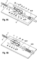
- Figure 1A schematically shows a first embodiment of a sample collection system according to the invention in the initial state.
- the sample collection system contains an analytical aid 1, which is an analytical aid 1 arranged on an analysis band 2. Of the analysis band 2, only a section is shown.
- the analytical aid 1 contains a lancet 3 and a test element 4.
- the test element 4 has a test field 5 for analyzing a liquid sample, in particular for analyzing a blood sample.
- the analysis tape 2 can be moved further in the transport direction 6 by means of a transport device (not shown).
- the lancet 3 is arranged perpendicular to the transport direction 6 on the analytical aid 1.
- the sample collection system includes a coupling element 7 in the form of a gripper, which in Figure 1A is coupled to the lancet (first position of the analytical tool 1).
- the sample collection system further includes a drive unit 8 for driving movement of the coupling element 7.
- the drive unit 8 comprises a spring 9 as a mechanical energy storage 10, a motor 11, a link 12 as a mechanical motion converter 13 and a driver 14, the mechanical energy storage 10, the motor 11 and the link body 16 of the link 12 coupled together as a drive element 15.
- the spring 9 is stretched (charged mechanical energy storage 10).
- the gate 12 includes the gate body 16, which has a slide guide 17.
- the slotted guide 17 has the shape of a arranged between two minima 18 maximum 19 and is symmetrical. In the slotted guide 17 engages an engagement member 34 of the coupling element 7 a.
- the coupling element 7 is arranged stationary in relation to the possible direction of movement 20 of the link body 16. It can only be moved perpendicular to this direction of movement 20 by the slide guide 17, in which engages its engagement member 34.
- the coupling element 7 is shown in its rest position 22.
- FIG. 1B shows the sample collection system according to the invention Figure 1A after triggering the lancing process.
- the tensioned spring relaxes 9 and the mechanical energy storage 10 is at least partially its stored energy via the drive element 15 as kinetic energy to the sliding body 16 from.
- the gate body 16 is thereby moved in a first direction 21 relative to the coupling element 7.
- the engagement element 34 of the coupling element 7 runs from the slide guide 17, whereby the coupling element 7 from the rest position in the in FIG. 1B shown deflected position 23 is raised.
- the coupling element 7 has reached the maximum 19 of the slotted guide 17.
- the coupled to the coupling element 7 lancet 3 is thereby also raised and pierces by this movement z.
- Figure 1C shows the sample collection system according to the invention Figures 1A and 1B after performing a piercing movement.
- the slide body 16 moves by the further relaxation of the spring 9 even further in the first direction 21 relative to the coupling element 7.
- the engagement member 34 of the coupling element 7 continues to drive the slide guide 17th from, until the spring 9 is completely relaxed.
- the coupling element 7 is located on the Height of the second minimum 24 of the slotted guide 17, so that it is again in its rest position 22.
- the lancet 3 is now withdrawn and thus has completed its piercing movement.
- FIG. 1D shows the sample collection system according to the invention FIGS. 1A to 1C After the analytical tool has been transported further.
- a transport device (not shown) transports the analytical aid 1 after the puncturing movement of the lancet 3 in the transport direction 6 relative to the coupling element 7 arranged in rest position 22 from the first to the second position, in which the coupling element 7 is coupled to the test element 4.
- the analysis tape 2, which carries the analytical aid 1 is forward-wound in the transport direction 6 until the desired second position for coupling the test element 4 to the coupling element 7 is achieved.
- Figure 1E shows the sample collection system according to the invention Figures 1A to 1D when performing the sample-taking motion by the test element.
- the test element 4 is coupled to the coupling element 7.
- the motor 11 moves the drive element 15 in the second direction 25, which is opposite to the first direction 21.
- the connecting element 16 coupled to the drive element 15 is moved in the second direction 25 relative to the coupling element 7.
- the engagement member 34 of the coupling member 7 moves while the slide guide 17 in the opposite direction as in FIG. 1B from, whereby the coupling element 7 from the rest position in the in Figure 1E shown deflected position 23 is raised.
- the coupling element 7 has reached the maximum 19 of the slotted guide 17.
- the movement of the coupling element 7 is transmitted to the test element 4 coupled to it, so that the test element 4 is likewise raised and, by means of this movement for sample taking, for example. B. is brought into contact with a blood sample on a body part of a patient.
- the spring 9 is tensioned by the motor 11 via the movement of the drive element 15 in the second direction 25 (charging of the mechanical energy store 10).
- the energy of the motor 11 is therefore used simultaneously for charging the mechanical energy storage device 10 and for moving the sliding body 16 in the second direction 25 relative to the coupling element 7.
- the slide 12 and the drive element 15 are designed so that they during the charging of the mechanical energy storage 10 energy of the motor 11 to the coupling element 7 for carrying out the sample-receiving movement transmitted through the test element 4. This is achieved in particular by the design of the coupling of the link 12, the motor 11 and the mechanical energy storage 10 to the drive element 15.
- Figure 1F shows the sample collection system according to the invention Figures 1A to 1E after performing a sample-taking motion.
- the slide body 16 is moved by the motor 11 via the drive element 15 in the second direction 25 relative to the coupling element 7, wherein at the same time the spring is further tensioned by the drive element.
- the engagement element 34 of the coupling element 7 continues to drive the link guide 17 until the spring 9 is fully tensioned and the motor 11 is stopped. In this state, the coupling element 7 is at the level of the first minimum 26 of the slotted guide 17, so that it is again in its rest position 22.
- the test element 4 is now withdrawn and has thus completed the sample recording process.
- the analysis belt 2 is transported further by the transport device (not shown) in the transport direction 6 relative to the coupling element 7 until the first position of the next analytical aid 1 arranged on the analysis belt 2 is reached again.
- the lancet 3 is coupled to the coupling element 7.
- the spring 9 is fully cocked and ready to release its energy to perform another piercing movement.
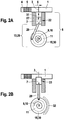
- FIG. 2A schematically shows a second embodiment of a sample collection system according to the invention in the initial state.
- the sample collection system includes an analytical tool, which may be a single or an analytical tool 1 disposed on an analysis band.
- the analytical aid 1 contains a lancet 3 and a test element 4.
- the test element 4 has a test field 5 for analyzing a liquid sample, in particular for analyzing a blood sample.
- the analytical aid 1 can be moved further in the transport direction 6 by means of a transport device (not shown).
- the lancet 3 is arranged perpendicular to the transport direction 6 on the analytical aid 1.
- the sample collection system includes a coupling element 7 in the form of a plunger, which is guided by a guide 27 in the direction of the analytical aid, wherein the coupling element 7 in FIG. 2A can be coupled to the lancet 3 (first position of the analytical Aid 1).
- the sample collection system further includes a drive unit 8 for driving movement of the coupling element 7.
- the drive unit 8 comprises a spring 9 as a mechanical energy store 10, a motor 11 and a connecting rod drive 28 as a mechanical motion converter 13.
- the spring 9 is tensioned (charged mechanical energy store 10).
- the connecting rod drive 28 comprises a connecting rod 29 and a drive rotor 30 which cooperate with the coupling element 7 so that a rotating movement of the drive rotor 30 via the connecting rod 29 in a (guided by the guide 27) linear movement 31 of the coupling element 7 is implemented.
- the motor 11 is coupled to the drive rotor 30 so that it can rotate it as needed (in particular for tensioning the spring 9) by a certain angle of rotation.
- the spring 9 is coupled to the drive rotor 30 so that it rotates the drive rotor 30 by a certain angle of rotation when it passes from the tensioned to the relaxed state.
- the spring 9 outputs the stored energy as kinetic energy to the drive rotor 30.
- the drive rotor 30 is coupled via the connecting rod 29 to the coupling element 7. Therefore, the drive rotor 30 is a drive element 15, which couples the motor 11, the mechanical energy storage 10 (spring 9) and the coupling element 7 with each other. In FIG. 2A the coupling element 7 is shown in its rest position 22.
- FIG. 2B shows the sample collection system according to the invention FIG. 2A after triggering the lancing process.
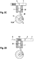
- Figure 2C shows the sample collection system according to the invention FIGS. 2A and 2B after performing a piercing movement.
- the drive rotor 30 rotates by the further relaxation of the spring 9 even further in the first direction of rotation 32 until the spring 9 is substantially completely relaxed.
- the connecting rod 29 is again retracted from the analytical aid, so that the coupling element has also been moved back into its rest position 22.
- the lancet 3 is retracted again and thus has completed its piercing movement.
- FIG. 2D shows the sample collection system according to the invention FIGS. 2A to 2C after the analytical tool has been transported.
- a transport device (not shown) transports the analytical aid 1 after the puncturing movement of the lancet 3 in the transport direction 6 relative to the coupling element 7 arranged in rest position 22 from the first to the second position, in which the coupling element 7 can be coupled to the test element 4.
- Figure 2E shows the sample collection system according to the invention FIGS. 2A to 2D when performing the sample-taking motion by the test element.
- the test element 4 is coupled to the coupling element 7.
- the motor 11 moves the drive rotor 30 (drive member 15) in the second rotational direction 33, which is opposite to the first rotational direction 32.
- the connecting rod 29 coupled to the drive rotor 30 is again moved in the direction of the analytical aid, whereby the coupling element 7 (guided by the guide 27) from the rest position into the in Figure 2E shown deflected position 23 is raised.
- the movement of the coupling element 7 is transmitted to the test element 4 coupled to it, so that the test element 4 is likewise raised and, by means of this movement for sample taking, for example.
- B. is brought into contact with a blood sample on a body part of a patient.
- the lifting of the test element 4 is in Figure 2E shown only schematically by raising the test field 5, wherein the analytical tool 1 is moved in practice at least partially, preferably completely, with the test element 4.
- Figure 2F shows the sample collection system according to the invention FIGS. 2A to 2E after performing a sample-taking motion.
- FIGS. 2A to 2F can now repeat itself with a new analytical tool 1.
Claims (4)
- Système d'obtention d'échantillon pour obtenir un échantillon fluide, contenant au moins un auxiliaire d'analyse (1) qui présente une lancette (3) et un élément d'essai (4), et un accumulateur d'énergie mécanique (10) qui peut délivrer de l'énergie à la lancette (3) pour effectuer un mouvement de perçage, caractérisé en ce que le système d'obtention d'échantillon comprend des moyens de transfert qui sont accouplés à l'accumulateur d'énergie mécanique (10) et à l'auxiliaire d'analyse (1) de telle sorte qu'un mouvement des moyens de transfert transmette simultanément de l'énergie à l'accumulateur d'énergie mécanique (10) pour charger l'accumulateur d'énergie mécanique (10) et entraîne un mouvement de prélèvement d'échantillon de l'élément d'essai (4).
- Système d'obtention d'échantillon selon la revendication 1, caractérisé en ce que les moyens de transfert, par le biais d'un premier mouvement, transmettent l'énergie de l'accumulateur d'énergie mécanique (10) à la lancette (3) pour effectuer le mouvement de perçage et, par un deuxième mouvement, transmettent de l'énergie pour charger l'accumulateur d'énergie mécanique (10) et entraînent simultanément le mouvement de l'élément d'essai (4).
- Système d'obtention d'échantillon selon la revendication 2, dans lequel le premier mouvement s'effectue à une plus grande vitesse que le deuxième mouvement.
- Système d'obtention d'échantillon selon l'une quelconque des revendications 1 à 3, caractérisé en ce que les moyens de transfert comprennent un entraînement à bielle (28) ou un corps de coulisse (16) avec un guide à coulisse (17).
Applications Claiming Priority (3)
| Application Number | Priority Date | Filing Date | Title |
|---|---|---|---|
| EP06122214A EP1917909A1 (fr) | 2006-10-12 | 2006-10-12 | Dispositif et procédé pour l'extraction d'échantillon liquides |
| PCT/EP2007/060759 WO2008043780A1 (fr) | 2006-10-12 | 2007-10-10 | Système de prélèvement d'échantillon et procédé de prélèvement d'un échantillon liquide |
| EP07821127A EP2079364B1 (fr) | 2006-10-12 | 2007-10-10 | Système de prélèvement d'échantillon |
Related Parent Applications (2)
| Application Number | Title | Priority Date | Filing Date |
|---|---|---|---|
| EP07821127A Division EP2079364B1 (fr) | 2006-10-12 | 2007-10-10 | Système de prélèvement d'échantillon |
| EP07821127.3 Division | 2007-10-10 |
Publications (2)
| Publication Number | Publication Date |
|---|---|
| EP2168482A1 EP2168482A1 (fr) | 2010-03-31 |
| EP2168482B1 true EP2168482B1 (fr) | 2019-08-07 |
Family
ID=37914273
Family Applications (3)
| Application Number | Title | Priority Date | Filing Date |
|---|---|---|---|
| EP06122214A Ceased EP1917909A1 (fr) | 2006-10-12 | 2006-10-12 | Dispositif et procédé pour l'extraction d'échantillon liquides |
| EP09179103.8A Not-in-force EP2168482B1 (fr) | 2006-10-12 | 2007-10-10 | dispositif pour l'extraction d'échantillons liquides |
| EP07821127A Not-in-force EP2079364B1 (fr) | 2006-10-12 | 2007-10-10 | Système de prélèvement d'échantillon |
Family Applications Before (1)
| Application Number | Title | Priority Date | Filing Date |
|---|---|---|---|
| EP06122214A Ceased EP1917909A1 (fr) | 2006-10-12 | 2006-10-12 | Dispositif et procédé pour l'extraction d'échantillon liquides |
Family Applications After (1)
| Application Number | Title | Priority Date | Filing Date |
|---|---|---|---|
| EP07821127A Not-in-force EP2079364B1 (fr) | 2006-10-12 | 2007-10-10 | Système de prélèvement d'échantillon |
Country Status (9)
| Country | Link |
|---|---|
| US (1) | US9364172B2 (fr) |
| EP (3) | EP1917909A1 (fr) |
| JP (1) | JP2010505568A (fr) |
| CN (3) | CN103040476B (fr) |
| AT (1) | ATE478603T1 (fr) |
| CA (1) | CA2665787A1 (fr) |
| DE (1) | DE502007004873D1 (fr) |
| HK (3) | HK1135301A1 (fr) |
| WO (1) | WO2008043780A1 (fr) |
Families Citing this family (12)
| Publication number | Priority date | Publication date | Assignee | Title |
|---|---|---|---|---|
| US20060281187A1 (en) | 2005-06-13 | 2006-12-14 | Rosedale Medical, Inc. | Analyte detection devices and methods with hematocrit/volume correction and feedback control |
| EP3461406A1 (fr) | 2005-09-30 | 2019-04-03 | Intuity Medical, Inc. | Cartouche d'échantillonnage et d'analyse de fluide corporel multi-sites |
| DE502006004922D1 (de) * | 2006-08-02 | 2009-11-05 | Roche Diagnostics Gmbh | Blutentnahmesystem |
| JP5816080B2 (ja) | 2008-05-30 | 2015-11-17 | インテュイティ メディカル インコーポレイテッド | 体液採取装置及び採取部位インターフェイス |
| US9636051B2 (en) | 2008-06-06 | 2017-05-02 | Intuity Medical, Inc. | Detection meter and mode of operation |
| EP3106871B1 (fr) | 2009-11-30 | 2021-10-27 | Intuity Medical, Inc. | Procédé de vérification de la précision du fonctionnement d'un dispositif de surveillance d'analyte |
| US9717452B2 (en) * | 2010-12-30 | 2017-08-01 | Roche Diabetes Care, Inc. | Handheld medical diagnostic devices with lancing speed control |
| EP2676607B1 (fr) * | 2011-02-14 | 2016-04-20 | Asahi Polyslider Co., Ltd. | Dispositif de lancette |
| DE102011015758B4 (de) * | 2011-03-31 | 2013-08-01 | Gerresheimer Regensburg Gmbh | Stechvorrichtung mit Drehelement |
| US9782114B2 (en) | 2011-08-03 | 2017-10-10 | Intuity Medical, Inc. | Devices and methods for body fluid sampling and analysis |
| DE102014201076B3 (de) | 2014-01-22 | 2015-03-05 | Bruker Biospin Ag | Transportbehälter für einen NMR MAS-Rotor |
| DE102017212192B3 (de) * | 2017-07-17 | 2018-10-18 | Bruker Biospin Ag | Transporteinrichtung für einen NMR MAS Rotor in einen Probenkopf ("MAS Shuttle") |
Citations (1)
| Publication number | Priority date | Publication date | Assignee | Title |
|---|---|---|---|---|
| US20030211619A1 (en) * | 2002-05-09 | 2003-11-13 | Lorin Olson | Continuous strip of fluid sampling and testing devices and methods of making, packaging and using the same |
Family Cites Families (25)
| Publication number | Priority date | Publication date | Assignee | Title |
|---|---|---|---|---|
| DE8007991U1 (de) | 1980-03-22 | 1981-04-09 | Clinicon Mannheim GmbH, 6800 Mannheim | Blutlanzettenvorrichtung zur Entnahme von Blut für Diagnosezwecke |
| US4924879A (en) * | 1988-10-07 | 1990-05-15 | Brien Walter J O | Blood lancet device |
| DE4320463A1 (de) | 1993-06-21 | 1994-12-22 | Boehringer Mannheim Gmbh | Blutlanzettenvorrichtung zur Entnahme von Blut für Diagnosezwecke |
| US5762770A (en) | 1994-02-21 | 1998-06-09 | Boehringer Mannheim Corporation | Electrochemical biosensor test strip |
| DE19629657A1 (de) | 1996-07-23 | 1998-01-29 | Boehringer Mannheim Gmbh | Volumenunabhängiger diagnostischer Testträger und Verfahren zur Bestimmung von Analyt mit dessen Hilfe |
| DE19629656A1 (de) | 1996-07-23 | 1998-01-29 | Boehringer Mannheim Gmbh | Diagnostischer Testträger mit mehrschichtigem Testfeld und Verfahren zur Bestimmung von Analyt mit dessen Hilfe |
| DE19718081A1 (de) | 1997-04-29 | 1998-11-05 | Boehringer Mannheim Gmbh | Einweg Blutlanzette |
| DE19753847A1 (de) | 1997-12-04 | 1999-06-10 | Roche Diagnostics Gmbh | Analytisches Testelement mit Kapillarkanal |
| US6391005B1 (en) * | 1998-03-30 | 2002-05-21 | Agilent Technologies, Inc. | Apparatus and method for penetration with shaft having a sensor for sensing penetration depth |
| US7077828B2 (en) * | 1999-03-05 | 2006-07-18 | Roche Diagnostics Gmbh | Device for withdrawing blood for diagnostic applications |
| JP3845413B2 (ja) * | 2001-06-08 | 2006-11-15 | エフ ホフマン−ラ ロッシュ アクチェン ゲゼルシャフト | 体液サンプリング装置およびこのような装置とともに使用される試験媒体カセット |
| EP1437093B1 (fr) * | 2001-09-19 | 2011-05-04 | Terumo Kabushiki Kaisha | Appareil pour mesurer un composant et puce |
| US7303726B2 (en) * | 2002-05-09 | 2007-12-04 | Lifescan, Inc. | Minimal procedure analyte test system |
| CA2444630A1 (fr) * | 2002-10-15 | 2004-04-15 | Bayer Healthcare Llc | Mecanisme pour lancette |
| EP1424040A1 (fr) | 2002-11-26 | 2004-06-02 | Roche Diagnostics GmbH | Dispositif de test pour fluides corporels |
| KR100699214B1 (ko) | 2002-12-23 | 2007-03-28 | 에프. 호프만-라 로슈 아게 | 체액 검사 장치, 검사 카세트, 시험 배지 제공 방법, 및 체액 분석 방법 |
| DE10332488A1 (de) | 2003-07-16 | 2005-02-24 | Roche Diagnostics Gmbh | Analysegerät und Analyseverfahren für Körperflüssigkeiten |
| DE10343896A1 (de) | 2003-09-19 | 2005-04-28 | Roche Diagnostics Gmbh | Testgerät zur Untersuchung von Körperflüssigkeiten |
| US7909776B2 (en) * | 2004-04-30 | 2011-03-22 | Roche Diagnostics Operations, Inc. | Lancets for bodily fluid sampling supplied on a tape |
| AU2005201576B2 (en) * | 2004-05-07 | 2010-06-24 | F. Hoffmann-La Roche Ag | Process and device for producing an analytical tape for liquid samples |
| DE102004037270B4 (de) * | 2004-07-31 | 2008-01-31 | Roche Diagnostics Gmbh | Blutentnahmesystem zur Entnahme von Blut für Diagnosezwecke |
| DE102004059491B4 (de) * | 2004-12-10 | 2008-11-06 | Roche Diagnostics Gmbh | Lanzettenvorrichtung zum Erzeugen einer Einstichwunde und Lanzettenantriebs-Baugruppe |
| EP1709906A1 (fr) * | 2005-04-07 | 2006-10-11 | F. Hoffmann-La Roche Ag | Procédé et dispositif de prélèvement de sang |
| TW200711630A (en) * | 2005-08-12 | 2007-04-01 | Bayer Healthcare Llc | Integrated test system for monitoring bodily fluids |
| EP1790288A1 (fr) * | 2005-11-25 | 2007-05-30 | Roche Diagnostics GmbH | Lancette pliée |
-
2006
- 2006-10-12 EP EP06122214A patent/EP1917909A1/fr not_active Ceased
-
2007
- 2007-10-10 AT AT07821127T patent/ATE478603T1/de active
- 2007-10-10 WO PCT/EP2007/060759 patent/WO2008043780A1/fr active Application Filing
- 2007-10-10 DE DE502007004873T patent/DE502007004873D1/de active Active
- 2007-10-10 JP JP2009531834A patent/JP2010505568A/ja active Pending
- 2007-10-10 EP EP09179103.8A patent/EP2168482B1/fr not_active Not-in-force
- 2007-10-10 CN CN201210510367.9A patent/CN103040476B/zh not_active Expired - Fee Related
- 2007-10-10 EP EP07821127A patent/EP2079364B1/fr not_active Not-in-force
- 2007-10-10 CN CN201010591481XA patent/CN102008312B/zh not_active Expired - Fee Related
- 2007-10-10 CA CA002665787A patent/CA2665787A1/fr not_active Abandoned
- 2007-10-10 CN CN2007800377576A patent/CN101522102B/zh not_active Expired - Fee Related
-
2009
- 2009-04-10 US US12/422,021 patent/US9364172B2/en active Active
-
2010
- 2010-02-22 HK HK10101843.5A patent/HK1135301A1/xx not_active IP Right Cessation
-
2011
- 2011-07-11 HK HK11107137.6A patent/HK1153104A1/xx not_active IP Right Cessation
-
2013
- 2013-06-19 HK HK13107171.1A patent/HK1179847A1/xx not_active IP Right Cessation
Patent Citations (1)
| Publication number | Priority date | Publication date | Assignee | Title |
|---|---|---|---|---|
| US20030211619A1 (en) * | 2002-05-09 | 2003-11-13 | Lorin Olson | Continuous strip of fluid sampling and testing devices and methods of making, packaging and using the same |
Also Published As
| Publication number | Publication date |
|---|---|
| WO2008043780A1 (fr) | 2008-04-17 |
| ATE478603T1 (de) | 2010-09-15 |
| DE502007004873D1 (de) | 2010-10-07 |
| EP1917909A1 (fr) | 2008-05-07 |
| CN103040476A (zh) | 2013-04-17 |
| CN102008312B (zh) | 2013-01-02 |
| JP2010505568A (ja) | 2010-02-25 |
| US9364172B2 (en) | 2016-06-14 |
| CN102008312A (zh) | 2011-04-13 |
| CN103040476B (zh) | 2014-10-22 |
| CN101522102B (zh) | 2011-03-09 |
| HK1179847A1 (en) | 2013-10-11 |
| HK1135301A1 (en) | 2010-06-04 |
| EP2079364B1 (fr) | 2010-08-25 |
| US20090270763A1 (en) | 2009-10-29 |
| HK1153104A1 (en) | 2012-03-23 |
| CA2665787A1 (fr) | 2008-04-17 |
| EP2168482A1 (fr) | 2010-03-31 |
| CN101522102A (zh) | 2009-09-02 |
| EP2079364A1 (fr) | 2009-07-22 |
Similar Documents
| Publication | Publication Date | Title |
|---|---|---|
| EP2168482B1 (fr) | dispositif pour l'extraction d'échantillons liquides | |
| EP1880671B1 (fr) | Roue de lancettes | |
| EP1643909B1 (fr) | Appareil d'analyse de liquides organiques | |
| EP2139396B1 (fr) | Appareil de perçage et appareil d'analyse | |
| DE60310159T3 (de) | Vorrichtung und Verfahren zur Zufuhr und Analyse von einer physiologischen Flüssigkeit | |
| EP2130493B1 (fr) | Système d'analyse destiné à la détermination d'un analyte dans un liquide corporel, cartouche pour un appareil d'analyse et procédé de production d'une cartouche pour un appareil d'analyse. | |
| DE60221347T3 (de) | In-situ adapter für ein analyten-testgerät | |
| DE60213822T2 (de) | Entnahmevorrichtung für körperflüssigkeiten und testmedienskassette | |
| EP2190352B1 (fr) | Entraînement de combinaison pour un système d'obtention d'échantillons pour obtenir un échantillon liquide | |
| EP2205154B1 (fr) | Magasin a lancettes | |
| EP1997429B1 (fr) | Lancet flexible en une systeme de lancettes | |
| WO2004064636A1 (fr) | Dispositif et procede pour recueillir un liquide organique a des fins d'analyse | |
| EP1736100A1 (fr) | Appareil portable d'analyse des fluides corporels | |
| EP1714613A1 (fr) | Moyen d'analyse | |
| WO2008068215A2 (fr) | Dispositif et procédé pour analyser des liquides corporels | |
| WO2007065844A1 (fr) | Accessoire perforant reutilisable et procede de realisation d'un deplacement de perforation au moyen d'un accessoire perforant reutilisable | |
| EP2311374A1 (fr) | Appareil pour obtention et analyse du sang; mécanisme pour couplage d'une lancette | |
| EP2496140B1 (fr) | Système de saisie de lancette pour dispositif de lancettes | |
| EP1880670B1 (fr) | Multi-lancettes | |
| EP2059169B1 (fr) | Dispositif médical | |
| EP1529488A1 (fr) | Dispositif et procédé pour le prélèvement et l'analyse de liquides corporels |
Legal Events
| Date | Code | Title | Description |
|---|---|---|---|
| PUAI | Public reference made under article 153(3) epc to a published international application that has entered the european phase |
Free format text: ORIGINAL CODE: 0009012 |
|
| AC | Divisional application: reference to earlier application |
Ref document number: 2079364 Country of ref document: EP Kind code of ref document: P |
|
| AK | Designated contracting states |
Kind code of ref document: A1 Designated state(s): AT BE BG CH CY CZ DE DK EE ES FI FR GB GR HU IE IS IT LI LT LU LV MC MT NL PL PT RO SE SI SK TR |
|
| 17P | Request for examination filed |
Effective date: 20100708 |
|
| 17Q | First examination report despatched |
Effective date: 20110322 |
|
| RAP1 | Party data changed (applicant data changed or rights of an application transferred) |
Owner name: ROCHE DIABETES CARE GMBH Owner name: F. HOFFMANN-LA ROCHE AG |
|
| STAA | Information on the status of an ep patent application or granted ep patent |
Free format text: STATUS: EXAMINATION IS IN PROGRESS |
|
| GRAP | Despatch of communication of intention to grant a patent |
Free format text: ORIGINAL CODE: EPIDOSNIGR1 |
|
| STAA | Information on the status of an ep patent application or granted ep patent |
Free format text: STATUS: GRANT OF PATENT IS INTENDED |
|
| INTG | Intention to grant announced |
Effective date: 20181109 |
|
| GRAJ | Information related to disapproval of communication of intention to grant by the applicant or resumption of examination proceedings by the epo deleted |
Free format text: ORIGINAL CODE: EPIDOSDIGR1 |
|
| STAA | Information on the status of an ep patent application or granted ep patent |
Free format text: STATUS: EXAMINATION IS IN PROGRESS |
|
| GRAP | Despatch of communication of intention to grant a patent |
Free format text: ORIGINAL CODE: EPIDOSNIGR1 |
|
| STAA | Information on the status of an ep patent application or granted ep patent |
Free format text: STATUS: GRANT OF PATENT IS INTENDED |
|
| INTC | Intention to grant announced (deleted) | ||
| INTG | Intention to grant announced |
Effective date: 20190226 |
|
| GRAS | Grant fee paid |
Free format text: ORIGINAL CODE: EPIDOSNIGR3 |
|
| GRAA | (expected) grant |
Free format text: ORIGINAL CODE: 0009210 |
|
| STAA | Information on the status of an ep patent application or granted ep patent |
Free format text: STATUS: THE PATENT HAS BEEN GRANTED |
|
| AC | Divisional application: reference to earlier application |
Ref document number: 2079364 Country of ref document: EP Kind code of ref document: P |
|
| AK | Designated contracting states |
Kind code of ref document: B1 Designated state(s): AT BE BG CH CY CZ DE DK EE ES FI FR GB GR HU IE IS IT LI LT LU LV MC MT NL PL PT RO SE SI SK TR |
|
| REG | Reference to a national code |
Ref country code: GB Ref legal event code: FG4D Free format text: NOT ENGLISH |
|
| REG | Reference to a national code |
Ref country code: CH Ref legal event code: EP Ref country code: AT Ref legal event code: REF Ref document number: 1162592 Country of ref document: AT Kind code of ref document: T Effective date: 20190815 |
|
| REG | Reference to a national code |
Ref country code: DE Ref legal event code: R096 Ref document number: 502007016745 Country of ref document: DE |
|
| REG | Reference to a national code |
Ref country code: IE Ref legal event code: FG4D Free format text: LANGUAGE OF EP DOCUMENT: GERMAN |
|
| REG | Reference to a national code |
Ref country code: NL Ref legal event code: MP Effective date: 20190807 |
|
| REG | Reference to a national code |
Ref country code: LT Ref legal event code: MG4D |
|
| PG25 | Lapsed in a contracting state [announced via postgrant information from national office to epo] |
Ref country code: PT Free format text: LAPSE BECAUSE OF FAILURE TO SUBMIT A TRANSLATION OF THE DESCRIPTION OR TO PAY THE FEE WITHIN THE PRESCRIBED TIME-LIMIT Effective date: 20191209 Ref country code: SE Free format text: LAPSE BECAUSE OF FAILURE TO SUBMIT A TRANSLATION OF THE DESCRIPTION OR TO PAY THE FEE WITHIN THE PRESCRIBED TIME-LIMIT Effective date: 20190807 Ref country code: FI Free format text: LAPSE BECAUSE OF FAILURE TO SUBMIT A TRANSLATION OF THE DESCRIPTION OR TO PAY THE FEE WITHIN THE PRESCRIBED TIME-LIMIT Effective date: 20190807 Ref country code: LT Free format text: LAPSE BECAUSE OF FAILURE TO SUBMIT A TRANSLATION OF THE DESCRIPTION OR TO PAY THE FEE WITHIN THE PRESCRIBED TIME-LIMIT Effective date: 20190807 Ref country code: BG Free format text: LAPSE BECAUSE OF FAILURE TO SUBMIT A TRANSLATION OF THE DESCRIPTION OR TO PAY THE FEE WITHIN THE PRESCRIBED TIME-LIMIT Effective date: 20191107 Ref country code: NL Free format text: LAPSE BECAUSE OF FAILURE TO SUBMIT A TRANSLATION OF THE DESCRIPTION OR TO PAY THE FEE WITHIN THE PRESCRIBED TIME-LIMIT Effective date: 20190807 |
|
| PG25 | Lapsed in a contracting state [announced via postgrant information from national office to epo] |
Ref country code: ES Free format text: LAPSE BECAUSE OF FAILURE TO SUBMIT A TRANSLATION OF THE DESCRIPTION OR TO PAY THE FEE WITHIN THE PRESCRIBED TIME-LIMIT Effective date: 20190807 Ref country code: LV Free format text: LAPSE BECAUSE OF FAILURE TO SUBMIT A TRANSLATION OF THE DESCRIPTION OR TO PAY THE FEE WITHIN THE PRESCRIBED TIME-LIMIT Effective date: 20190807 Ref country code: IS Free format text: LAPSE BECAUSE OF FAILURE TO SUBMIT A TRANSLATION OF THE DESCRIPTION OR TO PAY THE FEE WITHIN THE PRESCRIBED TIME-LIMIT Effective date: 20191207 Ref country code: GR Free format text: LAPSE BECAUSE OF FAILURE TO SUBMIT A TRANSLATION OF THE DESCRIPTION OR TO PAY THE FEE WITHIN THE PRESCRIBED TIME-LIMIT Effective date: 20191108 |
|
| PG25 | Lapsed in a contracting state [announced via postgrant information from national office to epo] |
Ref country code: TR Free format text: LAPSE BECAUSE OF FAILURE TO SUBMIT A TRANSLATION OF THE DESCRIPTION OR TO PAY THE FEE WITHIN THE PRESCRIBED TIME-LIMIT Effective date: 20190807 |
|
| PG25 | Lapsed in a contracting state [announced via postgrant information from national office to epo] |
Ref country code: IT Free format text: LAPSE BECAUSE OF FAILURE TO SUBMIT A TRANSLATION OF THE DESCRIPTION OR TO PAY THE FEE WITHIN THE PRESCRIBED TIME-LIMIT Effective date: 20190807 Ref country code: RO Free format text: LAPSE BECAUSE OF FAILURE TO SUBMIT A TRANSLATION OF THE DESCRIPTION OR TO PAY THE FEE WITHIN THE PRESCRIBED TIME-LIMIT Effective date: 20190807 Ref country code: EE Free format text: LAPSE BECAUSE OF FAILURE TO SUBMIT A TRANSLATION OF THE DESCRIPTION OR TO PAY THE FEE WITHIN THE PRESCRIBED TIME-LIMIT Effective date: 20190807 Ref country code: PL Free format text: LAPSE BECAUSE OF FAILURE TO SUBMIT A TRANSLATION OF THE DESCRIPTION OR TO PAY THE FEE WITHIN THE PRESCRIBED TIME-LIMIT Effective date: 20190807 Ref country code: DK Free format text: LAPSE BECAUSE OF FAILURE TO SUBMIT A TRANSLATION OF THE DESCRIPTION OR TO PAY THE FEE WITHIN THE PRESCRIBED TIME-LIMIT Effective date: 20190807 |
|
| PG25 | Lapsed in a contracting state [announced via postgrant information from national office to epo] |
Ref country code: MC Free format text: LAPSE BECAUSE OF FAILURE TO SUBMIT A TRANSLATION OF THE DESCRIPTION OR TO PAY THE FEE WITHIN THE PRESCRIBED TIME-LIMIT Effective date: 20190807 Ref country code: IS Free format text: LAPSE BECAUSE OF FAILURE TO SUBMIT A TRANSLATION OF THE DESCRIPTION OR TO PAY THE FEE WITHIN THE PRESCRIBED TIME-LIMIT Effective date: 20200224 Ref country code: SK Free format text: LAPSE BECAUSE OF FAILURE TO SUBMIT A TRANSLATION OF THE DESCRIPTION OR TO PAY THE FEE WITHIN THE PRESCRIBED TIME-LIMIT Effective date: 20190807 Ref country code: CZ Free format text: LAPSE BECAUSE OF FAILURE TO SUBMIT A TRANSLATION OF THE DESCRIPTION OR TO PAY THE FEE WITHIN THE PRESCRIBED TIME-LIMIT Effective date: 20190807 |
|
| REG | Reference to a national code |
Ref country code: CH Ref legal event code: PL |
|
| REG | Reference to a national code |
Ref country code: DE Ref legal event code: R097 Ref document number: 502007016745 Country of ref document: DE |
|
| PLBE | No opposition filed within time limit |
Free format text: ORIGINAL CODE: 0009261 |
|
| STAA | Information on the status of an ep patent application or granted ep patent |
Free format text: STATUS: NO OPPOSITION FILED WITHIN TIME LIMIT |
|
| PG2D | Information on lapse in contracting state deleted |
Ref country code: IS |
|
| PG25 | Lapsed in a contracting state [announced via postgrant information from national office to epo] |
Ref country code: CH Free format text: LAPSE BECAUSE OF NON-PAYMENT OF DUE FEES Effective date: 20191031 Ref country code: LI Free format text: LAPSE BECAUSE OF NON-PAYMENT OF DUE FEES Effective date: 20191031 Ref country code: LU Free format text: LAPSE BECAUSE OF NON-PAYMENT OF DUE FEES Effective date: 20191010 |
|
| 26N | No opposition filed |
Effective date: 20200603 |
|
| REG | Reference to a national code |
Ref country code: BE Ref legal event code: MM Effective date: 20191031 |
|
| PG25 | Lapsed in a contracting state [announced via postgrant information from national office to epo] |
Ref country code: BE Free format text: LAPSE BECAUSE OF NON-PAYMENT OF DUE FEES Effective date: 20191031 Ref country code: SI Free format text: LAPSE BECAUSE OF FAILURE TO SUBMIT A TRANSLATION OF THE DESCRIPTION OR TO PAY THE FEE WITHIN THE PRESCRIBED TIME-LIMIT Effective date: 20190807 |
|
| GBPC | Gb: european patent ceased through non-payment of renewal fee |
Effective date: 20191107 |
|
| PG25 | Lapsed in a contracting state [announced via postgrant information from national office to epo] |
Ref country code: FR Free format text: LAPSE BECAUSE OF NON-PAYMENT OF DUE FEES Effective date: 20191031 Ref country code: GB Free format text: LAPSE BECAUSE OF NON-PAYMENT OF DUE FEES Effective date: 20191107 Ref country code: IE Free format text: LAPSE BECAUSE OF NON-PAYMENT OF DUE FEES Effective date: 20191010 |
|
| REG | Reference to a national code |
Ref country code: AT Ref legal event code: MM01 Ref document number: 1162592 Country of ref document: AT Kind code of ref document: T Effective date: 20191010 |
|
| PG25 | Lapsed in a contracting state [announced via postgrant information from national office to epo] |
Ref country code: AT Free format text: LAPSE BECAUSE OF NON-PAYMENT OF DUE FEES Effective date: 20191010 |
|
| PGFP | Annual fee paid to national office [announced via postgrant information from national office to epo] |
Ref country code: DE Payment date: 20200916 Year of fee payment: 14 |
|
| PG25 | Lapsed in a contracting state [announced via postgrant information from national office to epo] |
Ref country code: CY Free format text: LAPSE BECAUSE OF FAILURE TO SUBMIT A TRANSLATION OF THE DESCRIPTION OR TO PAY THE FEE WITHIN THE PRESCRIBED TIME-LIMIT Effective date: 20190807 |
|
| PG25 | Lapsed in a contracting state [announced via postgrant information from national office to epo] |
Ref country code: HU Free format text: LAPSE BECAUSE OF FAILURE TO SUBMIT A TRANSLATION OF THE DESCRIPTION OR TO PAY THE FEE WITHIN THE PRESCRIBED TIME-LIMIT; INVALID AB INITIO Effective date: 20071010 Ref country code: MT Free format text: LAPSE BECAUSE OF FAILURE TO SUBMIT A TRANSLATION OF THE DESCRIPTION OR TO PAY THE FEE WITHIN THE PRESCRIBED TIME-LIMIT Effective date: 20190807 |
|
| REG | Reference to a national code |
Ref country code: DE Ref legal event code: R119 Ref document number: 502007016745 Country of ref document: DE |
|
| PG25 | Lapsed in a contracting state [announced via postgrant information from national office to epo] |
Ref country code: DE Free format text: LAPSE BECAUSE OF NON-PAYMENT OF DUE FEES Effective date: 20220503 |