EP2168426A1 - Agricultural machine - Google Patents
Agricultural machine Download PDFInfo
- Publication number
- EP2168426A1 EP2168426A1 EP09075433A EP09075433A EP2168426A1 EP 2168426 A1 EP2168426 A1 EP 2168426A1 EP 09075433 A EP09075433 A EP 09075433A EP 09075433 A EP09075433 A EP 09075433A EP 2168426 A1 EP2168426 A1 EP 2168426A1
- Authority
- EP
- European Patent Office
- Prior art keywords
- drive
- coupling
- drive shaft
- brake portion
- brake
- Prior art date
- Legal status (The legal status is an assumption and is not a legal conclusion. Google has not performed a legal analysis and makes no representation as to the accuracy of the status listed.)
- Withdrawn
Links
- 230000008878 coupling Effects 0.000 claims abstract description 134
- 238000010168 coupling process Methods 0.000 claims abstract description 134
- 238000005859 coupling reaction Methods 0.000 claims abstract description 134
- 230000001681 protective effect Effects 0.000 claims abstract description 6
- 230000000694 effects Effects 0.000 claims abstract description 5
- 230000007246 mechanism Effects 0.000 claims description 38
- 239000002783 friction material Substances 0.000 claims description 3
- 230000003247 decreasing effect Effects 0.000 claims description 2
- 238000000034 method Methods 0.000 claims description 2
- 230000008901 benefit Effects 0.000 description 6
- 230000005540 biological transmission Effects 0.000 description 6
- 230000008859 change Effects 0.000 description 3
- 230000007423 decrease Effects 0.000 description 2
- 230000000903 blocking effect Effects 0.000 description 1
- 230000001419 dependent effect Effects 0.000 description 1
- 239000000463 material Substances 0.000 description 1
- 230000009467 reduction Effects 0.000 description 1
- 239000004575 stone Substances 0.000 description 1
Images


Classifications
-
- A—HUMAN NECESSITIES
- A01—AGRICULTURE; FORESTRY; ANIMAL HUSBANDRY; HUNTING; TRAPPING; FISHING
- A01D—HARVESTING; MOWING
- A01D78/00—Haymakers with tines moving with respect to the machine
- A01D78/08—Haymakers with tines moving with respect to the machine with tine-carrying rotary heads or wheels
- A01D78/10—Haymakers with tines moving with respect to the machine with tine-carrying rotary heads or wheels the tines rotating about a substantially vertical axis
- A01D78/1057—Drive mechanisms
-
- A—HUMAN NECESSITIES
- A01—AGRICULTURE; FORESTRY; ANIMAL HUSBANDRY; HUNTING; TRAPPING; FISHING
- A01D—HARVESTING; MOWING
- A01D75/00—Accessories for harvesters or mowers
- A01D75/18—Safety devices for parts of the machines
- A01D75/182—Avoiding overload
-
- F—MECHANICAL ENGINEERING; LIGHTING; HEATING; WEAPONS; BLASTING
- F16—ENGINEERING ELEMENTS AND UNITS; GENERAL MEASURES FOR PRODUCING AND MAINTAINING EFFECTIVE FUNCTIONING OF MACHINES OR INSTALLATIONS; THERMAL INSULATION IN GENERAL
- F16D—COUPLINGS FOR TRANSMITTING ROTATION; CLUTCHES; BRAKES
- F16D43/00—Automatic clutches
- F16D43/02—Automatic clutches actuated entirely mechanically
- F16D43/20—Automatic clutches actuated entirely mechanically controlled by torque, e.g. overload-release clutches, slip-clutches with means by which torque varies the clutching pressure
- F16D43/21—Automatic clutches actuated entirely mechanically controlled by torque, e.g. overload-release clutches, slip-clutches with means by which torque varies the clutching pressure with friction members
- F16D43/213—Automatic clutches actuated entirely mechanically controlled by torque, e.g. overload-release clutches, slip-clutches with means by which torque varies the clutching pressure with friction members with axially applied torque-limiting friction surfaces
- F16D43/215—Automatic clutches actuated entirely mechanically controlled by torque, e.g. overload-release clutches, slip-clutches with means by which torque varies the clutching pressure with friction members with axially applied torque-limiting friction surfaces with flat friction surfaces, e.g. discs
Definitions
- the invention relates to an agricultural machine according to the preamble of claim 1.
- Such an agricultural machine comprises a drive device for driving the processing members, in particular ground or crop processing members of an agricultural machine, such as, for example, a mower, tedder or rotary harrow.
- each of the processing members usually comprises arms with tines fastened thereto.
- the arms are arranged with respect to each other in such a manner that the arms of adjacent processing members rotate between each other.
- the processing members thus have overlapping paths of movement and should, therefore, be moved synchronously.
- EP 1 258 187 A2 discloses a drive mechanism for agricultural machines comprising a main drive shaft and two drive sections for driving a group of processing members.
- Each drive section comprises a drive shaft and an overload coupling which, in the case of an overload, falls back to a rest moment.
- the drive shafts are in line.
- a catching device is provided between the drive shafts.
- the catching device is a device to allow a maximum angular rotation between the two drive shafts and consequently the groups of processing members.
- the group of processing members in question is completely blocked and disconnected from the drive mechanism by means of the overload coupling.
- the other group of processing members continues to rotate until the catching device does not allow further relative rotation because a maximum angular rotation has been reached. Consequently, the second group of processing members will also be blocked and the overload coupling present in this drive section will be disengaged.
- the processing members will not be stopped in one go, but in two phases.
- a further advantage of the drive mechanism according to EP 1 258 187 A2 is that the load is distributed over the two drive sections, in which case there is provided for each drive section an overload coupling with a maximum load of 50% of the maximum load of the main drive shaft.
- an overload coupling with a maximum load of 50% of the maximum load of the main drive shaft.
- the invention aims at providing an alternative drive mechanism for an agricultural machine, which reduces the risk of damage of the drive mechanism or processing members in the case of an overload of one or more of the processing members.
- the drive mechanism according to the invention enables an angular rotation between the two drive shafts in the case of an overload of one of the drive shafts, i.e. that the load becomes higher than a maximum operative load level.
- the load level at which this happens is usually higher than the normal operative load of the drive shaft in question. It is possible that during normal use of the agricultural machine there already occurs an angular rotation between the two drive shafts, for example with flexible coupling elements in the drive mechanism, but this angular rotation is usually smaller than the angular rotation which occurs in the case of overload.
- the angular rotation between the two drive shafts which are preferably in line, is used to slow down the not overloaded drive shaft.
- This slowing down is effected by creating, at the angular rotation, a coupling between the non-overloaded drive shaft and a part of the agricultural machine that is not co-rotatable with the drive shafts, for example the frame or a housing of the drive mechanism mounted on the frame.
- This coupling can be effected by pushing a friction surface which co-rotates which the drive shaft against a friction surface which does not co-rotate with the drive shaft in question.
- a mechanism which, at the angular rotation, in the case of overload, brings the drive shaft from a clearance position in which the drive shaft can rotate freely, into a blocking position in which the drive shaft is coupled with a part of the agricultural machine which is not capable of co-rotating with the drive shaft and, as a result thereof, can no longer rotate freely with respect to the frame of the agricultural machine.
- the drive shaft which, initially, is not overloaded will also have a load which is higher than the maximum load level of the overload coupling and, as a result thereof, said drive shaft will disengage.
- Such a drive mechanism has the advantage that only a peak load will be exerted on the blocked drive section.
- the second drive section is slowed down with respect to the frame. There is thus effected a disengagement of the drive of both drive sections without the risk of damage of the processing members resulting from asynchronous movement of the processing members of the different drive sections.
- the drive mechanism has the additional advantage that the maximum load in each drive section is determined by the drive section itself, because the drive sections are not interconnected by means of a catching device or the like. It is thus possible to select a maximum load for each drive section by means of the overload coupling of the drive section in question. The maximum load per drive section can therefore differ to a considerable extent.
- the angular rotation required for slowing down can, for example, be obtained by using a flexible coupling in the partial drive of the overloaded drive shaft, or an overload coupling.
- a flexible coupling is a coupling which, depending on the load, allows an angular rotation, for example by placing a torsion element in the drive mechanism.
- An overload coupling disengages at least partially when the load comes above a certain level.
- This is, for example, a coupling in which, in the case of a load above the maximum load, a rest moment is transferred, or a coupling which completely disengages in the case of overload, for example a coupling comprising elements which break in the case of a too high load, for example breaking bolts, or a cam switch coupling or a ratchet slip coupling.
- the advantage of an overload coupling is that the maximum load can be set individually for each drive section, for example 60 percent of the maximum output of the main drive shaft. It is then also possible to provide the different drive sections with different maximum loads, because the drive sections are disengaged.
- the overload coupling comprises a coupling which transfers the maximum load in the case of a load which is higher than the maximum load. Such a coupling does not fall back to a rest moment in the case of an overload, but the transferred moment remains equal to the moment in the case of a maximum load.
- Such an embodiment has the advantage that, if the sum of the maximum loads of the overload couplings of the different drive sections is larger than the maximum load of the main overload coupling in the drive shaft, the main overload coupling will also disengage in the case of overload of one of the drive sections.
- a friction coupling comprises two coupling halves which are contiguous to each other and which transfer a moment by means of friction between the two coupling halves. The moment to be transferred is limited to a maximum moment. If one of the coupling halves is driven at a higher load than the maximum load, the coupling halves will slip with respect to each other, in which case a moment is transferred which is equal to the maximum moment.
- each drive section may comprise a reset device which is configured to disengage, if desired, the drive section.
- Said reset device may comprise a clearance coupling which enables to rotate a drive section, in the direction opposite to the drive device, to the initial position.
- the reset device may be a disengaging device of the friction coupling itself, for example a hydraulic disengagement. It should be noted here that such reset devices can also be applied for other types of slip couplings.
- overload coupling which, at a load higher than the maximum load, transfers the maximum load, is an overrun coupling with pretension force.
- This overload coupling too comprises two coupling halves which rotate with respect to each other in the case of an overload and then transfer a moment which is equal to the moment in the case of maximum not disengaged load.
- the coupling brake device comprises:
- the second brake portion is mounted movably in axial direction on the second drive shaft, and there is provided a second abutment face which is not co-rotatable with the two drive shafts, against which the second brake portion can abut when the first and the second brake portion are pushed away from each other.
- a friction element for example an annular friction element, can be provided between the brake portions and the abutment face.
- the brake means comprise one or more balls which are each mounted in oppositely located ball tracks in the first brake portion and the second brake portion, wherein the ball tracks have a decreasing depth when viewed from a nominal angular position of the first brake portion, the second brake portion, respectively.
- the nominal angular position is the position of the drive shafts with respect to each other in the unloaded condition. In this case, an angular rotation between the two drive shafts is thus not involved.
- the depth of the ball tracks can be selected in such a manner that the ball present in the ball tracks is with some clearance between the two brake portions. If angular rotation occurs between the first and the second brake portion, the first and the second brake portion too will rotate with respect to each other. As a result, other parts of the ball track will be positioned opposite each other. Since the depth of the ball tracks from the nominal angular position decreases, the ball will be clamped between the two brake portions, and at further angular rotation, the ball will push the two brake portions away from each other. At the overload angular rotation, the ball pushes the two brake portions away from each other to such an extent that the brake portion in question will be pushed against the abutment face.
- a coupling is effected between the not overloaded drive shaft and a part of the agricultural machine, for example the frame, which is not co-rotatable with the two drive shafts. This coupling is maintained until the angular rotation between the two drive shafts is smaller than the overload angular rotation.
- the ball can be positioned in the nominal angular position in a manner in which it is clamped between the two brake portions, in which case, however, the brake portions do not yet abut against the one or more abutment faces.
- each ball track in the upwardly tapering part thereof has an effective angle with respect to the plane perpendicular to the longitudinal centre line of the respective drive shaft which is smaller than 30 degrees, for example 25 degrees.
- the ball track has around the nominal position a substantially flat part over an angle of not more than 20 degrees, preferably not more than 10 degrees, with respect to the centre line of the respective drive shaft.
- each of the ball tracks is bowl-shaped and each ball track extends over an angle of 65 to 85 degrees with respect to the centre line of the respective drive shaft.
- the brake device comprises one or more pretensioning elements to pretension the first and the second brake portion towards each other.
- pretensioning elements for example spring elements or rings of flexible material, it can be prevented that in normal operation the brake portions come into contact with the abutment faces and thus cause unintended braking or coupling.
- the invention also relates to a coupling brake device according to claim 16 or 17.
- the invention further relates to a method of protecting a drive device for two or more overlapping groups of processing members of an agricultural machine, comprising the steps of:
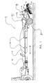
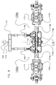
- FIGS 1 and 2 show a tedder denoted as a whole by reference numeral 1.
- the tedder comprises a frame 2 comprising a front end which is configured to be coupled to a pulling vehicle in order to be moved in the direction of travel R.
- a wheel set 3 Near the rear end of the frame 2 there is provided a wheel set 3 to support the frame 2.
- carrier arms 4 At the rear end of the frame 2 there are mounted two carrier arms 4 which extend at opposite sides of the frame 2.
- Each of the carrier arms 4 supports eight rotatable processing members 5.
- the processing members 5 comprise a number of arms 6 having a number of tines 7.
- a drive mechanism 8, shown in more detail in Figure 3 is provided for driving the processing members 5 in a rotating manner.
- the carrier arms 4 are configured to be folded up to a transport position in which the carrier arms 4 with processing members 5 will be positioned on the supports 9.
- the drive mechanism 8 comprises a main drive shaft 10 which, at one end, is configured to be connected to a drive source, and which, at the other end, is connected to a gear box 11.
- a main overload coupling 30 which maximises the drive capacity of the entire drive mechanism 8.
- the gear box 11 is further operatively connected to two drive sections 8a, 8b which each comprise a drive shaft 14a, 14b.
- drive couplings 12 which, via a first transmission 13, are connected to a drive shaft 14a, 14b.
- Each drive shaft 14a, 14b comprises for each of the eight processing members 5 a second transmission 15 and a shaft 16 by means of which the processing member 5 in question is drivable in a rotating manner.
- the processing members 5 rotate in overlapping paths of movement with respect to the adjacent processing members 5.
- the processing members 5 are driven in turn in opposite directions of rotation so that the arms 6 with tines 7 of different processing members 5 does not prevent each other from rotating.
- the processing members 5 do have a free angle of rotation, i.e. an angle over which a processing member 5 can rotate with respect to an adjacent processing member 5 without abutting against the adjacent processing member 5.
- Said free angle of rotation depends on the design of the processing members 5. For example, for a rotary harrow having two arms per processing member, the free angle of rotation can be maximally 90 degrees in both directions. In an embodiment of a tedder as shown in Figures 1 and 2 , this free angle of rotation of the processing members 5 is between 5 degrees and 20 degrees, for example 10 degrees, in both directions.
- a free angle of rotation of 10 degrees for the processing members 5 is a free angle of rotation of 30 degrees for the drive shafts 14 with respect to each other.
- the drive device 8 comprises in each of the drive sections 8a, 8b an overload coupling 17.
- the overload coupling 17 comprises a breaking bolt 18 which breaks in the case of a load greater than the maximally desired operative load, as a result of which the drive shaft 14a, 14b in question is disconnected from the main drive shaft 10.
- Each of the overload couplings 17 is set at a maximum operative load which is lower than the maximum load of the main overload coupling 30 in the main drive shaft 10.
- the maximum load of each of the overload couplings 17 can be 17.55% to 75% of the maximum load of the main overload coupling 30 in the main drive shaft 10. This has the advantage that the maximum load of the components of the individual drive sections 8a, 8b is lower than the maximum load of the entire drive mechanism 8.
- the drive device 8 further comprises a coupling brake device 19 comprising a first brake portion 19a and a second brake portion 19b.
- Figure 4 shows the coupling brake device 19 in more detail.
- the first brake portion 19a and the second brake portion 19b are each rotationally fixed by means of a key 22, but mounted movably in axial direction on the first drive shaft 14a, the second drive shaft 14b, respectively.
- the coupling brake device 19 further comprises four balls 21 which are provided in the oppositely located ball tracks 20.
- first brake portion 19a is shown in more detail.
- second brake portion 19b is designed analogously.
- the two brake portions 19a, 19b are pretensioned towards each other by annular spring elements 23.
- the two surfaces facing each other of the first brake portion 19a and the second brake portion 19b will be closest possible to each other.
- the bowl-shaped ball tracks 20 are located opposite each other and the distance between the bottoms of the ball tracks 20 is greater than the diameter of the ball 21.
- the brake portions 19a and 19b each have an annular abutment face 24 which is located opposite annular abutment faces which are provided on a housing 26 of the drive mechanism 8.
- the housing 26 is rigidly connected to the frame 2 of the agricultural machine 1 and cannot rotate with the drive shafts 14a, 14b.
- the friction rings 27 are loose elements.
- the bowl-shaped ball tracks 20 will move with respect to each other and the distance between the bottoms located opposite each other of the ball tracks 20 will decrease.
- the balls 21 will be clamped between the two brake portions 19a, 19b and at a further angular rotation the two brake portions 19a, 19b will be moved from each other by the balls 21 against pretension of the spring elements 23.
- the abutment faces 24, 25 will be pushed against the friction rings 27 so that there will be created a coupling between the brake portions 19a, 19b and the housing 26. This coupling will make it impossible for the brake portions 19a, 19b to rotate further with respect to each other.
- the main overload coupling 30 will disengage so that both drive sections 8a, 8b will substantially synchronously come to a standstill.
- Figure 8 shows an alternative embodiment of a drive device 118 according to the invention.
- the drive device 108 comprises a main drive shaft 110 which, at one end, is configured to be connected to a drive source, and which, at the other end, is connected to a gear box 111.
- a main overload coupling 130 which maximises the drive capacity of the entire drive mechanism 108.
- the gear box 111 is further operatively connected to two drive sections 108a, 108b which each comprise a drive shaft 114a, 114b.
- drive couplings 112 which, via a first transmission 13, are connected to a drive shaft 114a, 114b.
- Each drive shaft 114a, 114b comprises for each of the eight processing members 5 a second transmission 115 and a shaft 116 by means of which the processing member 5 in question is drivable in a rotating manner.
- a coupling brake device 119 In order to effect, in the case of overload of one of the drive sections 108a, 108b, blockage of the other drive section 108b, 108a, there is provided a coupling brake device 119 according to the invention.
- Said coupling brake device 119 comprising brake portions 119a, 119b and balls 121 is designed analogously to the above described coupling brake device 19 and will not be explained here in further detail.
- a flexible coupling 150 in each of the drive sections 108a, 108b is provided in each of the drive sections 108a, 108b.
- a flexible coupling 150 for example a torsion element, allows an angular rotation in a drive mechanism as a result of the load in said drive section 108a, 108b. Consequently, also in the case of normal load, the flexible coupling 150 will allow an angular rotation in the drive section.
- the same angular rotation will occur in both flexible couplings 150.
- the flexibility of the flexible couplings 150 is selected in such a manner that, in the case of a normal operative load, the angular rotation between the two drive shafts 114a, 114b will not become so great that the processing members 5 of the different drive sections 108a, 108b can touch each other.
- the angular rotation between the first drive shaft 14a and the second drive shaft 14b do differ substantially. This difference in angular rotation is used, according to the invention, to couple the drive shaft of the not overloaded drive section to the frame of the agricultural machine by means of the coupling brake device 119.
- overload coupling 17 of Figure 3 comprising breaking bolts 18, or the flexible couplings 150 of Figure 8
- each of the drive sections a coupling which transfers the maximum load in the case of a load higher than the maximum load.
- a coupling does not fall back to a rest moment in the case of an overload, but the transferred moment remains equal to the moment in the case of a maximum load.
- the main overload coupling will also disengage in the case of overload of one of the drive sections. In such a case, the overload couplings of the drive sections will be overloaded only for a very short period of time.
- a friction coupling comprises two coupling halves which are contiguous to each other and which transfer a moment by means of friction between the two coupling halves. The moment to be transferred is limited to a maximum moment. If one of the coupling halves is driven at a higher load than the maximum load, the coupling halves will slip with respect to each other, in which case a moment is transferred which is equal to the maximum moment.
- each drive section may comprise a reset device which is configured to disengage, if desired, the drive section.
- Said reset device may comprise a clearance coupling which enables to rotate a drive section, in the direction opposite to the drive device, to the initial position.
- the reset device may be a disengaging device of the friction coupling itself, for example a hydraulic disengagement. It should be noted here that such reset devices can also be applied for other types of slip couplings.
- the latter automatically move to the normal initial position under the influence of the spring elements 23 which are mounted in the coupling brake device.
- Said spring elements 23 can move the brake portions 19a, 19b to the nominal positions by pushing the brake portions towards each other. By this pushing, the balls 21 will bring the brake portions 19a, 19b back to the nominal position.
- Another overload coupling which, in the case of a load higher than the maximum load, transfers the maximum load, is an overrun coupling with pretension force.
- This overload coupling too comprises two coupling halves which rotate with respect to each other in the case of an overload and then transfer a moment which is equal to the moment in the case of maximum not disengaged load.
Landscapes
- Life Sciences & Earth Sciences (AREA)
- Environmental Sciences (AREA)
- Engineering & Computer Science (AREA)
- General Engineering & Computer Science (AREA)
- Mechanical Engineering (AREA)
- Transmission Devices (AREA)
- Agricultural Machines (AREA)
Abstract
Description
- The invention relates to an agricultural machine according to the preamble of
claim 1. Such an agricultural machine comprises a drive device for driving the processing members, in particular ground or crop processing members of an agricultural machine, such as, for example, a mower, tedder or rotary harrow. - In general, in agriculture there is a trend to enlarge the machines in use in order thus to enable a more efficient agricultural operation on a piece of land. With agricultural machines comprising rotating processing members this leads typically to an increasingly larger working width, and an increasing number of processing members being arranged in one row.
- During processing ground or a crop which is lying on the ground it is possible that one of the processing members gets stuck on an obstacle, for example a pole, tree or big stone. It will then suddenly no longer be possible for the processing member in question to rotate, while it is still being driven by the associated drive shaft. As a result thereof, the load which is exerted on the drive mechanism of the agricultural machine will suddenly increase quickly, resulting in a great risk of damage of the drive. In particular, there is a great risk of the tine wheels of a transmission being damaged as a result of an overload.
- It is known to place an overload protection on the main drive mechanism of a drive device in order to disconnect, at such a suddenly increasing load, the drive mechanism from the driving source, for example the motor of a tractor, in order to limit the maximum load and thus to prevent damage of the drive mechanism.
- However, in particular in the case of larger agricultural machines, in which a larger number of processing members should be driven simultaneously, the mass moment of inertia of the drive device and the processing members is accordingly greater. Suddenly stopping such a large mass which is interconnected via the drive mechanism may still provide a momentary load which may lead to damage of the drive mechanism.
- Moreover, an increased number of processing members also results in an increased total load which is required for driving all processing members. As a result, the components of the drive mechanism should be designed as stronger ones.
- In order to prevent the drive mechanism from being damaged, it would be possible, by means of an overload coupling, to disconnect only the blocked processing member from the drive mechanism at a too great load, so that the other processing members will be free to continue to rotate. However, this is only possible if the paths of movement of the processing members do not overlap.
- However, in a number of uses, such as embodiments of mowers, tedders or rotary harrows, the paths of movement of the processing members overlap. For example, in the case of a specific type of tedder, each of the processing members usually comprises arms with tines fastened thereto. The arms are arranged with respect to each other in such a manner that the arms of adjacent processing members rotate between each other. The processing members thus have overlapping paths of movement and should, therefore, be moved synchronously.
- If, in such an agricultural machine, only the processing member which is suddenly blocked is disconnected, the arms of the adjacent processing member will run into the arms of the blocked processing member. This may lead to damage of the arms, for example serious deformation or breakage of the arms or the tines attached thereto. In such an agricultural machine, such a single disconnection of a single processing member is therefore unwanted.
-
EP 1 258 187 A2 - When one of the processing members is blocked by an obstacle, the group of processing members in question is completely blocked and disconnected from the drive mechanism by means of the overload coupling. However, the other group of processing members continues to rotate until the catching device does not allow further relative rotation because a maximum angular rotation has been reached. Consequently, the second group of processing members will also be blocked and the overload coupling present in this drive section will be disengaged. By using this drive mechanism, the processing members will not be stopped in one go, but in two phases.
- A further advantage of the drive mechanism according to
EP 1 258 187 A2 - The invention aims at providing an alternative drive mechanism for an agricultural machine, which reduces the risk of damage of the drive mechanism or processing members in the case of an overload of one or more of the processing members.
- This object is achieved by means of an agricultural machine comprising:
- a frame,
- two or more processing members, which are movably attached to the frame, and
- a drive device which is configured to drive the processing members, wherein the drive device comprises:
- a main drive shaft,
- two drive sections which are connected to the main drive shaft and which are each configured to drive one or more of the two or more processing members, wherein each drive section comprises a drive shaft,
- a protective device which enables a certain angular rotation between the two drive shafts in the case of an overload of one of the two drive shafts, and
- a coupling brake device which is configured to effect, at the angular rotation between the two drive shafts, a coupling between the other drive shaft and a part of the agricultural machine that is not co-rotatable with the two drive shafts.
- The drive mechanism according to the invention enables an angular rotation between the two drive shafts in the case of an overload of one of the drive shafts, i.e. that the load becomes higher than a maximum operative load level. The load level at which this happens is usually higher than the normal operative load of the drive shaft in question. It is possible that during normal use of the agricultural machine there already occurs an angular rotation between the two drive shafts, for example with flexible coupling elements in the drive mechanism, but this angular rotation is usually smaller than the angular rotation which occurs in the case of overload.
- Subsequently, in the case of overload, the angular rotation between the two drive shafts, which are preferably in line, is used to slow down the not overloaded drive shaft. This slowing down is effected by creating, at the angular rotation, a coupling between the non-overloaded drive shaft and a part of the agricultural machine that is not co-rotatable with the drive shafts, for example the frame or a housing of the drive mechanism mounted on the frame.
- This coupling can be effected by pushing a friction surface which co-rotates which the drive shaft against a friction surface which does not co-rotate with the drive shaft in question. In an alternative embodiment, there can be effected a positively locked coupling between the non-overloaded drive shaft and the part of the agricultural machine which is not capable of co-rotating with the drive shaft. For this purpose, there is provided a mechanism which, at the angular rotation, in the case of overload, brings the drive shaft from a clearance position in which the drive shaft can rotate freely, into a blocking position in which the drive shaft is coupled with a part of the agricultural machine which is not capable of co-rotating with the drive shaft and, as a result thereof, can no longer rotate freely with respect to the frame of the agricultural machine.
- Through this coupling, the drive shaft which, initially, is not overloaded will also have a load which is higher than the maximum load level of the overload coupling and, as a result thereof, said drive shaft will disengage.
- Such a drive mechanism has the advantage that only a peak load will be exerted on the blocked drive section. For, the second drive section is slowed down with respect to the frame. There is thus effected a disengagement of the drive of both drive sections without the risk of damage of the processing members resulting from asynchronous movement of the processing members of the different drive sections.
- The drive mechanism has the additional advantage that the maximum load in each drive section is determined by the drive section itself, because the drive sections are not interconnected by means of a catching device or the like. It is thus possible to select a maximum load for each drive section by means of the overload coupling of the drive section in question. The maximum load per drive section can therefore differ to a considerable extent.
- The angular rotation required for slowing down can, for example, be obtained by using a flexible coupling in the partial drive of the overloaded drive shaft, or an overload coupling. A flexible coupling is a coupling which, depending on the load, allows an angular rotation, for example by placing a torsion element in the drive mechanism.
- An overload coupling disengages at least partially when the load comes above a certain level. This is, for example, a coupling in which, in the case of a load above the maximum load, a rest moment is transferred, or a coupling which completely disengages in the case of overload, for example a coupling comprising elements which break in the case of a too high load, for example breaking bolts, or a cam switch coupling or a ratchet slip coupling. The advantage of an overload coupling is that the maximum load can be set individually for each drive section, for example 60 percent of the maximum output of the main drive shaft. It is then also possible to provide the different drive sections with different maximum loads, because the drive sections are disengaged.
- In one embodiment, the overload coupling comprises a coupling which transfers the maximum load in the case of a load which is higher than the maximum load. Such a coupling does not fall back to a rest moment in the case of an overload, but the transferred moment remains equal to the moment in the case of a maximum load. Such an embodiment has the advantage that, if the sum of the maximum loads of the overload couplings of the different drive sections is larger than the maximum load of the main overload coupling in the drive shaft, the main overload coupling will also disengage in the case of overload of one of the drive sections.
- An example of such a coupling is a friction coupling. A friction coupling comprises two coupling halves which are contiguous to each other and which transfer a moment by means of friction between the two coupling halves. The moment to be transferred is limited to a maximum moment. If one of the coupling halves is driven at a higher load than the maximum load, the coupling halves will slip with respect to each other, in which case a moment is transferred which is equal to the maximum moment.
- If a friction coupling is overloaded, it may be desirable to bring the drive mechanism back into the initial position. For this purpose, each drive section may comprise a reset device which is configured to disengage, if desired, the drive section. Said reset device may comprise a clearance coupling which enables to rotate a drive section, in the direction opposite to the drive device, to the initial position. As an alternative, the reset device may be a disengaging device of the friction coupling itself, for example a hydraulic disengagement. It should be noted here that such reset devices can also be applied for other types of slip couplings.
- Another overload coupling which, at a load higher than the maximum load, transfers the maximum load, is an overrun coupling with pretension force. This overload coupling too comprises two coupling halves which rotate with respect to each other in the case of an overload and then transfer a moment which is equal to the moment in the case of maximum not disengaged load.
- In one embodiment, the coupling brake device comprises:
- a first brake portion which is mounted, rotationally fixed and movably in axial direction, on an end of the first drive shaft,
- a second brake portion which is mounted rotationally fixed on an end of the second drive shaft,
- brake means between the first and the second brake portion, which, at an angular rotation equal to or greater than the minimum angular rotation, push the first and the second brake portion away from each other, and
- a first abutment face which is not co-rotatable with the two drive shafts and against which the first brake portion can abut as a result of the first and the second brake portion being pushed away from each other.
- In such an embodiment, at the angular rotation of the first drive shaft with respect to the second drive shaft, as a result of overload, the first and the second brake portion will be pushed away from each other, so that the first brake portion will abut against the abutment face. As a result, the brake portion will be blocked with respect to the abutment face which is not co-rotatable with the drive shaft. By this coupling between the not blocked drive shaft and the abutment face the load in the not blocked drive section will increase and disengage the overload coupling of the second drive section and/or a main overload coupling, so that the second drive section too will no longer be driven. As a result, both groups of processing members will no longer be driven and come to a standstill without the risk of damage as a result of the asynchronous rotation of the two groups.
- In one embodiment, the second brake portion is mounted movably in axial direction on the second drive shaft, and there is provided a second abutment face which is not co-rotatable with the two drive shafts, against which the second brake portion can abut when the first and the second brake portion are pushed away from each other. By providing two brake portions which are axially movable with respect to the respective drive shaft, the slowing down force, which is obtained by pushing the first and the second brake portion away from each other and thus pushing the first and the second brake portion against the abutment faces, can be increased.
- In one embodiment, a friction element, for example an annular friction element, can be provided between the brake portions and the abutment face.
- In one embodiment, the brake means comprise one or more balls which are each mounted in oppositely located ball tracks in the first brake portion and the second brake portion, wherein the ball tracks have a decreasing depth when viewed from a nominal angular position of the first brake portion, the second brake portion, respectively. The nominal angular position is the position of the drive shafts with respect to each other in the unloaded condition. In this case, an angular rotation between the two drive shafts is thus not involved.
- In the nominal angular position, the depth of the ball tracks can be selected in such a manner that the ball present in the ball tracks is with some clearance between the two brake portions. If angular rotation occurs between the first and the second brake portion, the first and the second brake portion too will rotate with respect to each other. As a result, other parts of the ball track will be positioned opposite each other. Since the depth of the ball tracks from the nominal angular position decreases, the ball will be clamped between the two brake portions, and at further angular rotation, the ball will push the two brake portions away from each other. At the overload angular rotation, the ball pushes the two brake portions away from each other to such an extent that the brake portion in question will be pushed against the abutment face. As a result, a coupling is effected between the not overloaded drive shaft and a part of the agricultural machine, for example the frame, which is not co-rotatable with the two drive shafts. This coupling is maintained until the angular rotation between the two drive shafts is smaller than the overload angular rotation.
- It should be noted that the ball can be positioned in the nominal angular position in a manner in which it is clamped between the two brake portions, in which case, however, the brake portions do not yet abut against the one or more abutment faces.
- In one embodiment, each ball track in the upwardly tapering part thereof has an effective angle with respect to the plane perpendicular to the longitudinal centre line of the respective drive shaft which is smaller than 30 degrees, for example 25 degrees. In a further embodiment, the ball track has around the nominal position a substantially flat part over an angle of not more than 20 degrees, preferably not more than 10 degrees, with respect to the centre line of the respective drive shaft.
- In one embodiment, each of the ball tracks is bowl-shaped and each ball track extends over an angle of 65 to 85 degrees with respect to the centre line of the respective drive shaft.
- In one embodiment, the brake device comprises one or more pretensioning elements to pretension the first and the second brake portion towards each other. By means of such pretensioning elements, for example spring elements or rings of flexible material, it can be prevented that in normal operation the brake portions come into contact with the abutment faces and thus cause unintended braking or coupling.
- The invention also relates to a coupling brake device according to claim 16 or 17.
- The invention further relates to a method of protecting a drive device for two or more overlapping groups of processing members of an agricultural machine, comprising the steps of:
- providing a main drive mechanism and at least two drive sections, wherein each drive section has a drive shaft for driving one or more of the two or more processing members, wherein the two drive shafts are substantially in line,
- providing an overload protection in the first and the second drive shaft, wherein the overload protection is adjusted to a load which is lower than a load required for the entire drive mechanism, but higher than a load required for the drive mechanism of the respective drive shaft,
- in the case of overload of the first drive shaft, enabling an angular rotation of the first drive shaft with respect to the second drive shaft, and
- slowing down the second drive shaft by coupling the second drive shaft to a part of the drive device that is not co-rotatable with the first or the second drive shaft.
- The invention will hereinafter be explained in further detail on the basis of an exemplary embodiment, under reference to the accompanying drawing in which:
-
Figures 1 and2 are a side view and a top view of an agricultural machine according to the invention; -
Figure 3 is a schematic top view of the drive device of the agricultural machine ofFigures 1 and2 ; -
Figure 4 is a schematic top view of the coupling brake device ofFigure 3 ; -
Figures 5, 6 and 7 are a side view, a cross-sectional view and a second side view of a brake portion according to the invention, and -
Figure 8 is a schematic top view of an alternative drive device according to the invention. -
Figures 1 and2 show a tedder denoted as a whole byreference numeral 1. The tedder comprises aframe 2 comprising a front end which is configured to be coupled to a pulling vehicle in order to be moved in the direction of travel R. Near the rear end of theframe 2 there is provided a wheel set 3 to support theframe 2. At the rear end of theframe 2 there are mounted twocarrier arms 4 which extend at opposite sides of theframe 2. - Each of the
carrier arms 4 supports eightrotatable processing members 5. Theprocessing members 5 comprise a number of arms 6 having a number of tines 7. Adrive mechanism 8, shown in more detail inFigure 3 , is provided for driving theprocessing members 5 in a rotating manner. Thecarrier arms 4 are configured to be folded up to a transport position in which thecarrier arms 4 withprocessing members 5 will be positioned on thesupports 9. There is provided a hydraulic circuit with actuators for folding in thecarrier arms 4 to the transport position and folding them out to the operative position. - The
drive mechanism 8 comprises amain drive shaft 10 which, at one end, is configured to be connected to a drive source, and which, at the other end, is connected to agear box 11. In the main drive shaft there is provided amain overload coupling 30 which maximises the drive capacity of theentire drive mechanism 8. Thegear box 11 is further operatively connected to twodrive sections drive shaft drive couplings 12 which, via afirst transmission 13, are connected to adrive shaft drive shaft second transmission 15 and ashaft 16 by means of which theprocessing member 5 in question is drivable in a rotating manner. - The
processing members 5 rotate in overlapping paths of movement with respect to theadjacent processing members 5. Theprocessing members 5 are driven in turn in opposite directions of rotation so that the arms 6 with tines 7 ofdifferent processing members 5 does not prevent each other from rotating. - Despite of the overlapping paths of movement the
processing members 5 do have a free angle of rotation, i.e. an angle over which aprocessing member 5 can rotate with respect to anadjacent processing member 5 without abutting against theadjacent processing member 5. Said free angle of rotation depends on the design of theprocessing members 5. For example, for a rotary harrow having two arms per processing member, the free angle of rotation can be maximally 90 degrees in both directions. In an embodiment of a tedder as shown inFigures 1 and2 , this free angle of rotation of theprocessing members 5 is between 5 degrees and 20 degrees, for example 10 degrees, in both directions. - Since the
second transmission 15 has a speed reduction of approximately a factor three of thedrive shaft shaft 16, a free angle of rotation of 10 degrees for theprocessing members 5 is a free angle of rotation of 30 degrees for the drive shafts 14 with respect to each other. - According to the invention it is possible to use this free rotation space to slow down a not overloaded drive section if the other drive section would be stopped as a result of overload. This makes it possible to prevent damage to the agricultural machine as a result of not synchronously moving processing members.
- The
drive device 8 comprises in each of thedrive sections overload coupling 17. Theoverload coupling 17 comprises a breakingbolt 18 which breaks in the case of a load greater than the maximally desired operative load, as a result of which thedrive shaft main drive shaft 10. - Each of the
overload couplings 17 is set at a maximum operative load which is lower than the maximum load of themain overload coupling 30 in themain drive shaft 10. For example, the maximum load of each of theoverload couplings 17 can be 17.55% to 75% of the maximum load of themain overload coupling 30 in themain drive shaft 10. This has the advantage that the maximum load of the components of theindividual drive sections entire drive mechanism 8. - The
drive device 8 further comprises acoupling brake device 19 comprising afirst brake portion 19a and asecond brake portion 19b. -
Figure 4 shows thecoupling brake device 19 in more detail. Thefirst brake portion 19a and thesecond brake portion 19b are each rotationally fixed by means of a key 22, but mounted movably in axial direction on thefirst drive shaft 14a, thesecond drive shaft 14b, respectively. In each of the circular surfaces located towards each other of thefirst brake portion 19a and thesecond brake portion 19b there are provided four bowl-shaped ball tracks 20 distributed over the circumference of the surfaces. Thecoupling brake device 19 further comprises fourballs 21 which are provided in the oppositely located ball tracks 20. - In
Figures 5, 6 and 7 , thefirst brake portion 19a is shown in more detail. Thesecond brake portion 19b is designed analogously. - With reference to
Figure 4 , the twobrake portions annular spring elements 23. As a result, the two surfaces facing each other of thefirst brake portion 19a and thesecond brake portion 19b will be closest possible to each other. In the nominal angular position of thefirst brake portion 19a and thesecond brake portion 19b, the bowl-shaped ball tracks 20 are located opposite each other and the distance between the bottoms of the ball tracks 20 is greater than the diameter of theball 21. - The
brake portions annular abutment face 24 which is located opposite annular abutment faces which are provided on ahousing 26 of thedrive mechanism 8. Thehousing 26 is rigidly connected to theframe 2 of theagricultural machine 1 and cannot rotate with thedrive shafts brake portions housing 26, respectively, there are provided friction rings 27 of friction material to improve the braking function between the abutment faces 24 and 25. The friction rings 27 are loose elements. As an alternative, it is also possible to apply friction material on one of the abutment faces 24, 25 or both of them. - At an angular rotation between the
first drive shaft 14a and thesecond drive shaft 14b and, consequently, between thefirst brake portion 19a and thesecond brake portion 19b, the bowl-shaped ball tracks 20 will move with respect to each other and the distance between the bottoms located opposite each other of the ball tracks 20 will decrease. As a result, theballs 21 will be clamped between the twobrake portions brake portions balls 21 against pretension of thespring elements 23. As a result, the abutment faces 24, 25 will be pushed against the friction rings 27 so that there will be created a coupling between thebrake portions housing 26. This coupling will make it impossible for thebrake portions - An overload of the
drive sections drive device 8. - At a simultaneous overload of both drive
sections main overload coupling 30 will disengage so that both drivesections - If an overload occurs in one of the
drive sections first drive section 8a, theoverload coupling 17 in thedrive section 8a concerned will disengage by breakage of the breakingbolt 18. As a result, thedisengaged drive section 8a will no longer be driven by themain drive shaft 10, while theother drive section 8b is still being driven. This results in an angular rotation between thefirst brake portion 19a of thedisengaged drive shaft 14a and thesecond brake portion 19b of thedrive shaft 14b which is still being driven. By the angular rotation the twobrake portions friction ring 27 will be clamped between the abutment faces 24 and 25. This results in a coupling between thedrive shaft 14b of thesecond drive section 8b and thehousing 26, and the load of thesecond drive section 8b will increase until it reaches the maximum load of theoverload coupling 17 of thesecond drive section 8b and disengages same by breaking thebreaking bolt 18. As a result, both drivesections main drive shaft 10. -
Figure 8 shows an alternative embodiment of a drive device 118 according to the invention. - Analogously to the drive device described above, the drive device 108 comprises a
main drive shaft 110 which, at one end, is configured to be connected to a drive source, and which, at the other end, is connected to agear box 111. In the main drive shaft there is provided amain overload coupling 130 which maximises the drive capacity of the entire drive mechanism 108. Thegear box 111 is further operatively connected to twodrive sections drive shaft first transmission 13, are connected to adrive shaft drive shaft second transmission 115 and ashaft 116 by means of which theprocessing member 5 in question is drivable in a rotating manner. - In order to effect, in the case of overload of one of the
drive sections other drive section coupling brake device 119 according to the invention. Saidcoupling brake device 119 comprisingbrake portions balls 121 is designed analogously to the above describedcoupling brake device 19 and will not be explained here in further detail. - In order to achieve the angular rotation required for the operation of the
coupling brake device 119, there is provided aflexible coupling 150 in each of thedrive sections flexible coupling 150, for example a torsion element, allows an angular rotation in a drive mechanism as a result of the load in saiddrive section flexible coupling 150 will allow an angular rotation in the drive section. However, when use is made of correspondingflexible couplings 150 in both drivesections drive sections flexible couplings 150. It is also possible that different loads will result in different angular rotations. The flexibility of theflexible couplings 150 is selected in such a manner that, in the case of a normal operative load, the angular rotation between the twodrive shafts processing members 5 of thedifferent drive sections - However, in the case of overload of one of the
drive sections first drive shaft 14a and thesecond drive shaft 14b do differ substantially. This difference in angular rotation is used, according to the invention, to couple the drive shaft of the not overloaded drive section to the frame of the agricultural machine by means of thecoupling brake device 119. - Subsequently, the load in the drive section blocked by the
coupling brake device 119 will increase. If the sum of the loads in both drivesections main overload coupling 130, themain overload coupling 130 will disengage, and the entire drive mechanism will no longer be driven. - It is possible to make the change in angular rotation of the flexible coupling dependent on the load level. In particular, it is possible to make the change in angular rotation small in the case of loads below the maximum load level of the
drive section drive section coupling brake device 119, while, in the case of overload, thecoupling brake device 119 will quickly couple the not overloaded drive section to thehousing 26 as a result of the angular rotation. - As an alternative for the
overload coupling 17 ofFigure 3 comprising breakingbolts 18, or theflexible couplings 150 ofFigure 8 , it is also possible to use other couplings, depending on the desired characteristics of the drive device. - It is, for example, possible to provide in each of the drive sections a coupling which transfers the maximum load in the case of a load higher than the maximum load. Such a coupling does not fall back to a rest moment in the case of an overload, but the transferred moment remains equal to the moment in the case of a maximum load. In such an embodiment, if the sum of the maximum loads of the maximum loads of the overload couplings of the different drive sections is larger than the maximum load of the main overload coupling in the drive shaft, the main overload coupling will also disengage in the case of overload of one of the drive sections. In such a case, the overload couplings of the drive sections will be overloaded only for a very short period of time.
- An example of such a coupling is a friction coupling. A friction coupling comprises two coupling halves which are contiguous to each other and which transfer a moment by means of friction between the two coupling halves. The moment to be transferred is limited to a maximum moment. If one of the coupling halves is driven at a higher load than the maximum load, the coupling halves will slip with respect to each other, in which case a moment is transferred which is equal to the maximum moment.
- If a friction coupling is overloaded, it may be desirable to bring the drive mechanism back into the initial position. For this purpose, each drive section may comprise a reset device which is configured to disengage, if desired, the drive section. Said reset device may comprise a clearance coupling which enables to rotate a drive section, in the direction opposite to the drive device, to the initial position. As an alternative, the reset device may be a disengaging device of the friction coupling itself, for example a hydraulic disengagement. It should be noted here that such reset devices can also be applied for other types of slip couplings.
- In one embodiment, it is possible that, in the case of disengagement of the drive sections, the latter automatically move to the normal initial position under the influence of the
spring elements 23 which are mounted in the coupling brake device. Saidspring elements 23 can move thebrake portions balls 21 will bring thebrake portions - Another overload coupling which, in the case of a load higher than the maximum load, transfers the maximum load, is an overrun coupling with pretension force. This overload coupling too comprises two coupling halves which rotate with respect to each other in the case of an overload and then transfer a moment which is equal to the moment in the case of maximum not disengaged load.
Claims (18)
- Agricultural machine (1), comprising:- a frame (2),
two or more processing members (5), which are movably attached to the frame, and- a drive device (8, 108) which is configured to drive the processing members, wherein the drive device comprises:- a main drive shaft (10, 110),- two drive sections (8a, 8b, 108a, 108b) which are connected to the main drive shaft and which are each configured to drive one or more of the two or more processing members (5), wherein each drive section comprises a drive shaft (14a, 14b, 114a, 114b),characterized in that the drive device further comprises:- a protective device (17, 150) which enables a certain angular rotation between the two drive shafts in the case of an overload of one of the two drive shafts, and- a coupling brake device (19, 119) which is configured to effect, at the angular rotation between the two drive shafts, a coupling between the other drive shaft and a part of the agricultural machine that is not co-rotatable with the two drive shafts. - Agricultural machine (1) according to claim 1, wherein the drive shafts (14a, 14b, 114a, 114b) are substantially in line.
- Agricultural machine (1) according to claim 1 or 2, wherein the protective device (17, 150) comprises an overload coupling (17).
- Agricultural machine (1) according to claim 3, wherein the protective device (17, 150) comprises an overload coupling (17) in each of the drive sections.
- Agricultural machine (1) according to claim 3 or 4, wherein the overload coupling comprises a coupling which transfers the maximum load in the case of a load which is higher than the maximum load.
- Agricultural machine (1) according to claim 5, wherein at least one drive section (8a, 8b) comprises a reset device which is configured to disengage, if desired, the drive section in such a manner that the drive section can be brought into a desired angular position with respect to the main drive shaft and/or other drive sections.
- Agricultural machine (1) according to claim 1, wherein the protective device (17, 150) comprises at least one flexible coupling (150) which allows an angular rotation between the two drive shafts (114a, 114b).
- Agricultural machine (1) according to one of claims 1-7, wherein the coupling brake device (19, 119) comprises:- a first brake portion (19a, 119a) which is mounted, rotationally fixed and movably in axial direction, on an end of the first drive shaft (14a, 114a),- a second brake portion (19b, 119b) which is mounted rotationally fixed on an end of the second drive shaft (14b, 114b),- brake means (20, 21) between the first and the second brake portion, which, at the angular rotation, push the first and the second brake portion away from each other, and- a first abutment face (25) which is not co-rotatable with the two drive shafts and against which the first brake portion can abut as a result of the first and the second brake portion being pushed away from each other.
- Agricultural machine (1) according to claim 8, wherein the second brake portion (19b, 119b) is mounted movably in axial direction on the second drive shaft (14b, 114b), and wherein there is provided a second abutment face (25) which is not co-rotatable with the two drive shafts and against which the second brake portion can abut as a result of the first and the second brake portion being pushed away from each other.
- Agricultural machine (1) according to claim 8 or 9, wherein the brake means (20, 21) comprise one or more balls (21) which are mounted in oppositely located ball tracks (20) in the first brake portion (19a, 119a) and the second brake portion (19b, 119b), wherein the ball tracks have a decreasing depth when viewed from a nominal angular position of the first brake portion, the second brake portion, respectively.
- Agricultural machine (1) according to claim 10, wherein the ball tracks (20) have an effective angle with respect to the plane perpendicular to the longitudinal centre line of the respective drive shaft which is smaller than 30 degrees, preferably smaller than 15 degrees.
- Agricultural machine (1) according to claim 8 or 9, wherein the brake means comprise cams that are upwardly tapering in tangential direction and are mounted on the first brake portion (19a, 119a) and the second brake portion (19b, 119b), which cams co-operate with each other.
- Agricultural machine (1) according to one of claims 8-12, wherein the abutment faces (25) and/or the faces (24) co-operating therewith of the first brake portion (19a, 119a) and the second brake portion (19b, 119b) are provided with a layer of friction material.
- Agricultural machine (1) according to one of claims 8-13, wherein one or more friction elements (27) are provided between the first brake portion (19a, 119a) and the first abutment face (25) and/or the second brake portion (19b, 119b) and the second abutment face (25).
- Agricultural machine (1) according to one of claims 8-14, wherein the coupling brake device (19, 119) comprises one or more pretensioning elements (23) to pretension the first brake portion (19a, 119a) and the second brake portion (19b, 119b) towards each other.
- A coupling brake device (19, 119) which is configured to effect, in the case of an angular rotation between two drive shafts (14a, 14b, 114a, 114b) of a drive device as a result of an overload of one of the two drive shafts, a coupling between the other drive shaft and a component which is not co-rotatable with the two drive shafts, in order thus to limit the angular rotation between the two drive shafts.
- The coupling brake device according to claim 16, wherein the coupling brake device (19, 119) comprises:- a first brake portion (19a, 119a) which is mounted, rotationally fixed and movably in axial direction, on an end of the first drive shaft (14a, 114a),- a second brake portion (19b, 119b) which is mounted rotationally fixed on an end of the second drive shaft (14b, 114b),- brake means (20, 21) between the first and the second brake portion, which, at the angular rotation, push the first and the second brake portion away from each other, and- a first abutment face (25) which is not co-rotatable with the two drive shafts and against which the first brake portion can abut as a result of the first and the second brake portion being pushed away from each other.
- Method of protecting a drive device (8) for two or more overlapping groups of processing members (5) of an agricultural machine (1), comprising the steps of:- providing a main drive mechanism (10) and at least two drive sections (8a, 8b), wherein each drive section has a drive shaft (14a, 14b) for driving one or more of the two or more processing members, wherein the two drive shafts are substantially in line,- providing an overload protection (17) in the first and the second drive shaft, wherein the overload protection is adjusted to a load which is lower than a load required for the entire drive mechanism, but higher than a load required for the drive mechanism of the respective drive shaft,characterized by the steps:- in the case of overload of the first drive shaft (14a), enabling an angular rotation of the first drive shaft with respect to the second drive shaft (14b), and- slowing down the second drive shaft by coupling the second drive shaft to a part of the drive device that is not co-rotatable with the first or the second drive shaft.
Applications Claiming Priority (1)
| Application Number | Priority Date | Filing Date | Title |
|---|---|---|---|
| NL1035973A NL1035973C (en) | 2008-09-24 | 2008-09-24 | AGRICULTURAL MACHINE. |
Publications (1)
| Publication Number | Publication Date |
|---|---|
| EP2168426A1 true EP2168426A1 (en) | 2010-03-31 |
Family
ID=40602460
Family Applications (1)
| Application Number | Title | Priority Date | Filing Date |
|---|---|---|---|
| EP09075433A Withdrawn EP2168426A1 (en) | 2008-09-24 | 2009-09-18 | Agricultural machine |
Country Status (3)
| Country | Link |
|---|---|
| US (1) | US8062136B2 (en) |
| EP (1) | EP2168426A1 (en) |
| NL (1) | NL1035973C (en) |
Families Citing this family (1)
| Publication number | Priority date | Publication date | Assignee | Title |
|---|---|---|---|---|
| US8911182B2 (en) * | 2010-05-28 | 2014-12-16 | Brandt Industries Ltd. | Agricultural equipment drive system |
Citations (4)
| Publication number | Priority date | Publication date | Assignee | Title |
|---|---|---|---|---|
| DE2407821A1 (en) * | 1974-02-19 | 1975-09-04 | Bautz Gmbh Josef | Safety device for mower rotary blade drive - consists of an overload coupling connected to the drive of each separate rotary cutter |
| US20020157363A1 (en) * | 2001-04-27 | 2002-10-31 | Kraus Timothy J. | Brake for a disc cutterbar |
| EP1258187A2 (en) | 2001-05-16 | 2002-11-20 | Wilhelm Stoll Maschinenfabrik GmbH | Drive system for agricultural machine |
| DE202007008591U1 (en) * | 2007-06-15 | 2007-08-23 | Gkn Walterscheid Gmbh | Drive arrangement, in particular for agricultural equipment |
Family Cites Families (10)
| Publication number | Priority date | Publication date | Assignee | Title |
|---|---|---|---|---|
| US2618136A (en) * | 1945-07-30 | 1952-11-18 | Falk Corp | Flexible shaft coupling with overload release |
| US3100974A (en) * | 1961-04-28 | 1963-08-20 | Ford Motor Co | Clutch |
| US3488980A (en) * | 1968-05-29 | 1970-01-13 | Deere & Co | Torque limiting clutch |
| US3600877A (en) * | 1969-05-02 | 1971-08-24 | Donald E Mccrary | Stripping-shredding method and apparatus |
| US4645472A (en) * | 1981-03-06 | 1987-02-24 | Power Transmission Technology, Inc. | Torque limiting clutch |
| US4401426A (en) * | 1981-03-06 | 1983-08-30 | Power Transmssion Technology, Inc. | Torque limiting clutch |
| US5129497A (en) * | 1991-07-25 | 1992-07-14 | Force Control Industries, Inc. | Torque limiting clutch |
| DE19951644A1 (en) * | 1999-10-27 | 2001-05-17 | Kemper Gmbh Maschf | Agricultural machine, in particular mower |
| US6447397B1 (en) * | 2000-10-13 | 2002-09-10 | Weasler Engineering, Inc. | Detent torque overload clutch |
| DE102006025455A1 (en) * | 2006-05-30 | 2007-12-20 | Claas Saulgau Gmbh | Attachment for harvesting stemmed crops |
-
2008
- 2008-09-24 NL NL1035973A patent/NL1035973C/en not_active IP Right Cessation
-
2009
- 2009-09-18 EP EP09075433A patent/EP2168426A1/en not_active Withdrawn
- 2009-09-24 US US12/565,851 patent/US8062136B2/en not_active Expired - Fee Related
Patent Citations (4)
| Publication number | Priority date | Publication date | Assignee | Title |
|---|---|---|---|---|
| DE2407821A1 (en) * | 1974-02-19 | 1975-09-04 | Bautz Gmbh Josef | Safety device for mower rotary blade drive - consists of an overload coupling connected to the drive of each separate rotary cutter |
| US20020157363A1 (en) * | 2001-04-27 | 2002-10-31 | Kraus Timothy J. | Brake for a disc cutterbar |
| EP1258187A2 (en) | 2001-05-16 | 2002-11-20 | Wilhelm Stoll Maschinenfabrik GmbH | Drive system for agricultural machine |
| DE202007008591U1 (en) * | 2007-06-15 | 2007-08-23 | Gkn Walterscheid Gmbh | Drive arrangement, in particular for agricultural equipment |
Also Published As
| Publication number | Publication date |
|---|---|
| NL1035973C (en) | 2010-03-25 |
| US8062136B2 (en) | 2011-11-22 |
| US20100071331A1 (en) | 2010-03-25 |
Similar Documents
| Publication | Publication Date | Title |
|---|---|---|
| US8474605B2 (en) | Conveyor drive shaft assembly with integrated torque limiting device | |
| EP3628144B1 (en) | Crop cutting device, agricultural machine comprising such crop cutting device and crop cutting method | |
| US4366666A (en) | Haymaking machine | |
| EP1862057B1 (en) | Attachment device for harvesting stalk crops | |
| US6718746B2 (en) | Drive arrangement for ensilage harvester discharge spout | |
| EP2422609B1 (en) | Drive arrangement for corn head equipped with or without a corn stalk chopper | |
| CN105309107A (en) | Cutting device for agricultural harvesters | |
| CN104675875A (en) | Torque limiter | |
| NL8204039A (en) | TORQUE LIMIT COUPLING. | |
| US8062136B2 (en) | Overload protection for an agricultural machine | |
| PL184316B1 (en) | Mowing apparatus | |
| RU2665620C2 (en) | Double ended extendable driveshaft for auto header hookup | |
| EP1854343B1 (en) | Coupling mechanism | |
| GB2069449A (en) | Loading equipment for agricultural bulk material | |
| EP3321533B1 (en) | Safety clutch for an agricultural vehicle or trailed accessory thereof | |
| EP2207411A1 (en) | Agricultural machine | |
| AU740416B2 (en) | A foldable agricultural machine, as well as a method of folding same from the working position into the transport position | |
| JP3408880B2 (en) | Transmission structure of rice transplanter | |
| NL1037396C2 (en) | AGRICULTURAL MACHINE. | |
| EP1977641B1 (en) | Harvesting device for harvesting stalk crops | |
| EP3750387A1 (en) | Agricultural trailing device | |
| RU2511306C2 (en) | Drive for load-transfer device of agricultural harvester | |
| EP3100606B1 (en) | Star-wheel rake | |
| JPH11266660A (en) | Combine | |
| JP2008074208A (en) | Tractor |
Legal Events
| Date | Code | Title | Description |
|---|---|---|---|
| PUAI | Public reference made under article 153(3) epc to a published international application that has entered the european phase |
Free format text: ORIGINAL CODE: 0009012 |
|
| AK | Designated contracting states |
Kind code of ref document: A1 Designated state(s): AT BE BG CH CY CZ DE DK EE ES FI FR GB GR HR HU IE IS IT LI LT LU LV MC MK MT NL NO PL PT RO SE SI SK SM TR |
|
| AX | Request for extension of the european patent |
Extension state: AL BA RS |
|
| 17P | Request for examination filed |
Effective date: 20100930 |
|
| 17Q | First examination report despatched |
Effective date: 20101119 |
|
| RAP1 | Party data changed (applicant data changed or rights of an application transferred) |
Owner name: LELY PATENT N.V. |
|
| GRAP | Despatch of communication of intention to grant a patent |
Free format text: ORIGINAL CODE: EPIDOSNIGR1 |
|
| STAA | Information on the status of an ep patent application or granted ep patent |
Free format text: STATUS: GRANT OF PATENT IS INTENDED |
|
| INTG | Intention to grant announced |
Effective date: 20180507 |
|
| GRAS | Grant fee paid |
Free format text: ORIGINAL CODE: EPIDOSNIGR3 |
|
| STAA | Information on the status of an ep patent application or granted ep patent |
Free format text: STATUS: THE APPLICATION HAS BEEN WITHDRAWN |
|
| 18W | Application withdrawn |
Effective date: 20180907 |